42
Feb 2005
| Date post: | 18-Dec-2015 |
| Category: |
Documents |
| Upload: | osborn-floyd |
| View: | 214 times |
| Download: | 0 times |

Feb 2005

For SKADS Meeting, Amsterdam, 24 February 2005
Overview of Australia’s NTD/SKA Activities for Mileura in WA
Presented by: Colin Jacka and John O’Sullivan24 February 2005

www.atnf.csiro.auMileura Site

www.atnf.csiro.auMileura, Pathway to SKA
150km
Perth 850km
Geraldton ~500km

www.atnf.csiro.auWhat is Planned for Mileura?
Mileura Widefield Array NTD/xNTD (CSIRO led) ― towards Australia’s SKA
LFD (MIT Haystack led) ― Aperture Array 100-300 MHz
Berkeley Array ― EOR experiment
CSIRO (Ron Ekers et al) ― for EOR
RQZ ― essential for all of the above

www.atnf.csiro.auRadio Quiet Zone activities
Working with Fed, State & Local govts towards establishing procedures to protect the radio quietness and set up the RQZ
With ACA to control licensed transmissions Within 100-300 km coordination zone
With WA Govt to control incidental transmissions via DAs Within 30 km development controls
RQZ regulations apply only to fixed development & services (not apply to mobiles, aircraft, emergency services, Defence)
Signage for mobiles, coordination with Defence, aircraft

www.atnf.csiro.auSKA Demonstrator in Australia
NTD (New Technology Demonstrator) Funded by Australian government and CSIRO as one of the MNRF- (Major New
Research Facility) funded projects over the period 2002 – 2007 Until June 2004, most of effort was on Luneburg Lenses From July 2004, the effort is associated with using Focal Plane Arrays (FPAs) Due for completion in July 2007 2 dishes fitted with Focal Plane Arrays at the Australian candidate SKA site at
Mileura in Western Australia (~ 26° 37' S, 117 ° 29.5' E) xNTD (Extended New Technology Demonstrator)
Builds upon the designs & deliverables from the NTD Extra funding obtained from CSIRO, 2005 – 2008 We now have the funding, but will not decide if xNTD is technically feasible until
Dec 2005, dependent on NTD progress in mitigating the technical risks $25m AUD, 2005 – 2008, 20 dishes with FPAs, at Mileura site A useful telescope in itself But a vision for xNTD to evolve into technology for SKA

www.atnf.csiro.au
SKA Technology Developments at CSIRO
Focal Plane Arrays
Antennas
Digital Processing
Receiver Designs
Software Systems
High-speed networking

www.atnf.csiro.auRequirements from MNRF Grant
Stated aims at 2002 MNRF initiation: To develop multi-beaming antenna technology
Advanced optical signal transport
Advanced signal processing schemes
Developing interference mitigation techniques
Integrated into an operating instrument which would benefit the development path towards the SKA
Would make use of project deliverables from other MNRF-funded projects eg CABB, MMIC, SKA Siting

www.atnf.csiro.auOverlap of xNTD and LFD
Infrastructure and radio-quiet zone site
Complementary frequency ranges
Wide field of view science
Technology behind the antennas Software
Digital Hardware using FPGAs: (reconfigurable design structures)
• LFD Receiver and NTD Beamformer
• Correlators
Signal Distribution

www.atnf.csiro.au
Establishment of Mileura site for Radio Science in WA
Technology, and a range of Radio Science
WA Govt support for the Infrastructure
WA Govt support for planning controls and negotiations with the traditional owners
WA Fellowship in Radio Astronomy is being established
CSIRO is collaborating with Curtin Uni on the RF-testing program, and we have further collaboration with UWA/Curtin for xNTD tasks

www.atnf.csiro.auSummary of Science with xNTD
xNTD is ideal for large-area surveys and has good surface brightness sensitivity. It is highly competitive with current/planned instruments
New science can be done with the xNTD if the specs / technical challenges can be met.
The xNTD is on the pathway to the SKA can add more and more collecting area
One-day workshop planned for early 2005 Engage and excite the entire astro community
Improve the xNTD science case

www.atnf.csiro.au
xNTD Parameters
Area = 4000 m2 (20 dishes, 180 baselines) Tsys = 50 K Frequency range = 0.8 – 1.8 GHz Bandwidth = 256 MHz Number of independent beams = 48
each beam 1 sq deg 48 sq deg FoV at 1.4 GHz
Maximum Baseline < 1000 m Full cross correlation all antennas Located in the RQZ at Mileura, Western Australia
ATA - A=10000m2, FoV=5.5 sq deg, BW=1GHz, Tsys=50K Parkes MB – A=3200m2, FoV=0.8 sq deg, Tsys=22K ATCA – A=1900m2, FoV=0.6 sq deg, Tsys=30K Arecibo – A=70000m2, FoV=0.02 sq deg, Tsys=35K

www.atnf.csiro.auMNRF Progress to date
Original NTD Project Plan Choose NTD concept by 30 June 2004
Choice became one of selecting from • Luneburg Lenses
• Cylinders
• Focal Plane Arrays
Until June 2004, most effort was on Luneburg Lenses
From that point on, the effort is on FPAs• Revised Preliminary NTD Project Plan 30 September 2004
• Present Plan caters for a number of scenarios in an ever-changing environment
• Now, have decoupled the 2 Project Plans

www.atnf.csiro.auWhat difference does the x make?
NTD Funded by existing, secured ATNF + MNRF funds 2 interconnected dishes, 15m diameter, each with focal
plane array, at proposed SKA site
xNTD Additional funding from CSIRO & State Gov 20 dishes, 15 m diameter, arranged in one group, genuine
micro-SKA, at proposed SKA site Project Plan: Design & Development Program until Dec
2005 is common for NTD and xNTD xNTD implementation phase from Jan 2006, as a result of
sufficient risk mitigation in areas of antenna, FPA, digital beamforming and correlator design

www.atnf.csiro.auChallenges for xNTD
Can we make small steerable dishes cheap enough? Cheap, high performance (wide band and polarization pure)
FPAs? Cheap, high performance integrated RXs? No self-generated RFI from RXs (or rejection schemes)? How to transport signals from FPA? DBF (efficient, cost-effective using FPGAs)? Calibration with synthesized varying beam patterns? Correlator (a very large effort) Data storage & transportation Remote operation as a NF from East Coast of Oz?
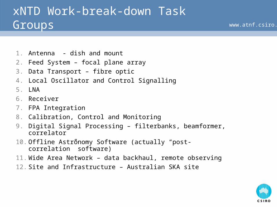
www.atnf.csiro.auxNTD Work-break-down Task Groups
1. Antenna - dish and mount
2. Feed System – focal plane array
3. Data Transport – fibre optic
4. Local Oscillator and Control Signalling
5. LNA
6. Receiver
7. FPA Integration
8. Calibration, Control and Monitoring
9. Digital Signal Processing – filterbanks, beamformer, correlator
10. Offline Astronomy Software (actually “post-correlation” software)
11. Wide Area Network – data backhaul, remote observing
12. Site and Infrastructure – Australian SKA site

www.atnf.csiro.auNTD Antenna System
Presently looking at 3 alternatives to meet the challenge of performance/cost The Indian PPD dish design New design using manufacturing techniques available in Australia Refurbishing 2 antennas from Fleurs (for NTD)

www.atnf.csiro.auAntennas for Extended NTD (xNTD)
Proposed project to extend the collecting area of the NTD array to 64m dish equivalent (~ 20 dishes)
Based on NTD technology, but will explore options for increased bandwidth (1GHz) and operating band (to 2.4GHz)
Shares infrastructure and software development with proposed MIT Mileura Wide-field Array Demonstrator (LFD)
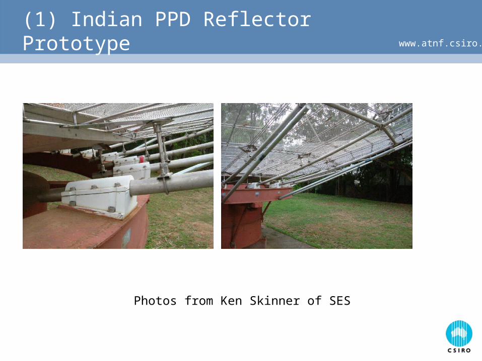
www.atnf.csiro.au(1) Indian PPD Reflector Prototype
Photos from Ken Skinner of SES

www.atnf.csiro.au(2) Reflector antenna options
Custom-built mesh reflector using NC machine tools “High-tech” solution with high accuracy, good repeatability, and
no tooling-up costs Local manufacture of prefabricated “flat-pack” reflector;
assemble on site Changing the geometry, e.g. offset or larger f / D, no problem Estimated reflector mass significantly < PPD Estimated cost > current PPD estimate

www.atnf.csiro.au“Flat-pack” Reflector Concept
Images & antenna concept from Ross Forsyth

www.atnf.csiro.au(1) Reflector antenna options
Refurbished dishes from the former Fleurs radiotelescope Two 14m dishes in apparently good condition still exist at the
Fleurs site (close to Badgery’s Creek, Sydney).
Estimated cost of transport + refurbishment ongoing
Equatorial mount – advantageous for simple FPA

www.atnf.csiro.auFleurs dishes

www.atnf.csiro.auFPA options
Collaborative development of “Vivaldi” array with ASTRON / U.Mass. Best option for short-term demonstrator
Tested wideband array technology
Limited operating band for SKA
Relatively complex manufacture
Alternate wideband arrays Looking towards the longer term to SKA
Inherently wideband structures
Foveated array with “natural” scaling of FoV

www.atnf.csiro.au
FPA system diagram
AD PFB
AD PFB
AD PFB
PFB
PFBbeam-former
Router
beam-former
Array element + integrated analogue receiver
Digital receiverRouter Beam-
former2nd stagefilterbank
To Correlator

www.atnf.csiro.auConclusions and next stages of work
Initial modelling of reflector + FPA system show that the NTD goals for FoV and operating frequency band are achievable using available technology.
Next stages: Collaborative development with e.g. U. Mass. towards prototype NTD
FPA Ongoing system optimization study across reflector optical system,
FPA, front end & ADC System integration of FPA, analogue and digital electronics:
“plumbing”, self RFI, power, thermal, structural, mechanical engineering.

www.atnf.csiro.auReceiver
200 RXs per dish
RF-CMOS chip from MIMIC project (Suzy Jackson) Re-spec’d for NTD/xNTD requirements
MIMIC for xNTD, but
For NTD: perhaps part of MIMIC chip, and separate backend
ICTC doing alternative backup discrete design for early requirements
Separate LNA for Tsys requirements (Paul Roberts)

www.atnf.csiro.auDigital Signal Processing
(John Bunton) Each dish produces 200x256x106x2x8 ~ 1 Tera bps Evaluate possibilities for commonality between
xNTD/LFD/CABB/ATA requirements Strong collaboration with MIT group; good interchange of ideas
between CSIRO and MIT White Paper developed at end of Dec 04 Inter-site extended visits of MIT/CSIRO personnel Buffer, beamformer, correlator
NTD ― 2 (not 20) complex beamformers, but one simple buffer/correlator
Also, taking wider view, looking at next generation telco technology for the Routing problem.
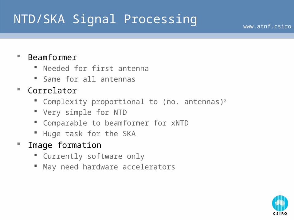
www.atnf.csiro.auNTD/SKA Signal Processing
Beamformer Needed for first antenna Same for all antennas
Correlator Complexity proportional to (no. antennas)2
Very simple for NTD Comparable to beamformer for xNTD Huge task for the SKA
Image formation Currently software only May need hardware accelerators
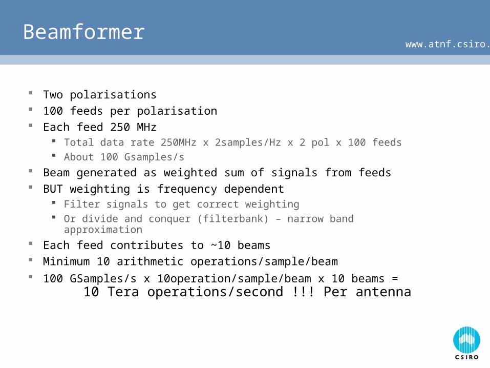
www.atnf.csiro.auBeamformer
Two polarisations 100 feeds per polarisation Each feed 250 MHz
Total data rate 250MHz x 2samples/Hz x 2 pol x 100 feeds About 100 Gsamples/s
Beam generated as weighted sum of signals from feeds BUT weighting is frequency dependent
Filter signals to get correct weighting Or divide and conquer (filterbank) – narrow band approximation
Each feed contributes to ~10 beams Minimum 10 arithmetic operations/sample/beam 100 GSamples/s x 10operation/sample/beam x 10 beams =
10 Tera operations/second !!! Per antenna

www.atnf.csiro.auCorrelator
Must form a product between each pair of antennas signals xNTD has 20 antennas x 2 pol = 380 different correlation 48 beams each 250 Mcomplex samples/s 7 operations per correlation 250x7 Moperations/correlation x 380 correlation x 48 beams
= 32 Tera operations/sec
SKA 250 times as many antennas, twice the bandwidth Task is 125,000 times harder

www.atnf.csiro.auHow
FPGAs Have 200 18bit multipliers adder@ 500MHz gives
200 Giga operations/s in a single package (50 per antenna)
Development in VHDL – reusable firmware
But still need to be smart in how we do the processing otherwise 10 Teraops/s goes to 100
High power autorouters 1000 of pins, route diff pairs for high speed interconnects
Without smart design the routing of the data will strangle the design
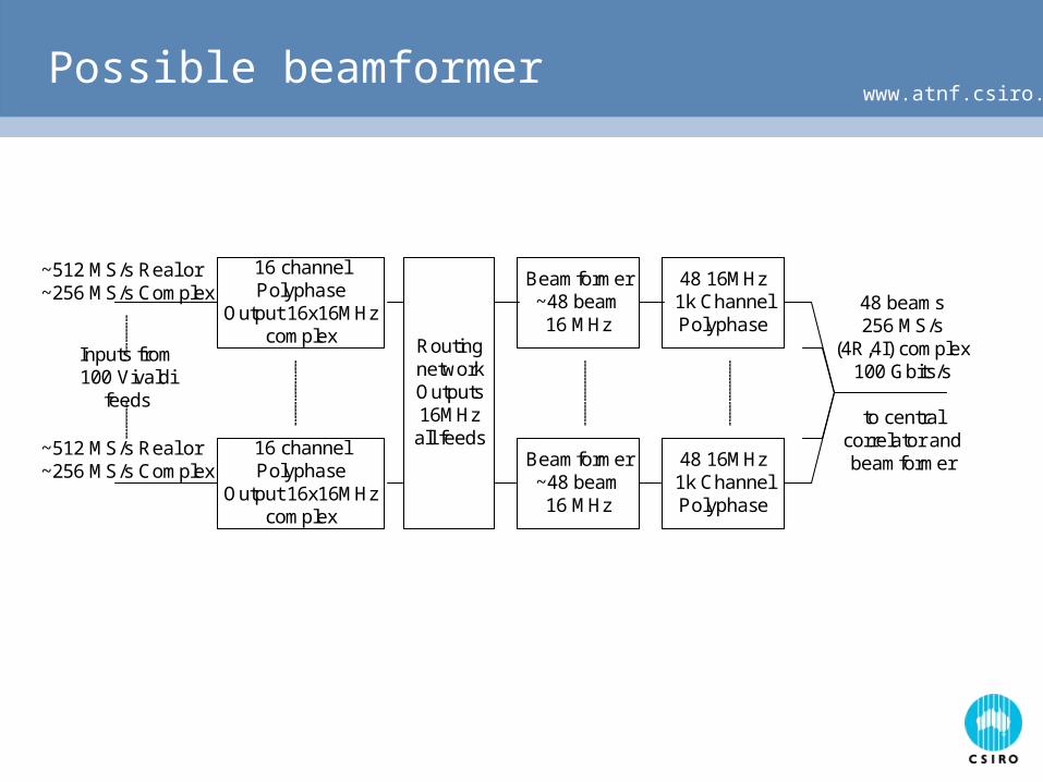
www.atnf.csiro.auPossible beamformer
16 channelPolyphase
Output 16x16MHzcomplex
16 channelPolyphase
Output 16x16MHzcomplex
~512 MS/s Real or~256 MS/s Complex
~512 MS/s Real or~256 MS/s Complex
Inputs from100 Vivaldi
feeds
RoutingnetworkOutputs16MHzall feeds
Beamformer~48 beam16 MHz
Beamformer~48 beam16 MHz
48 beams256 MS/s
(4R,4I) complex100 Gbits/s
to centralcorrelator andbeamformer
48 16MHz1k ChannelPolyphase
48 16MHz1k ChannelPolyphase
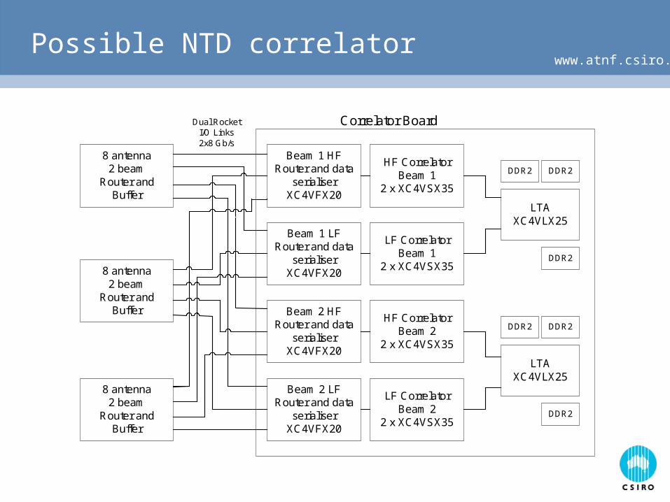
www.atnf.csiro.auPossible NTD correlator
8 antenna2 beam
Router andBuffer
8 antenna2 beam
Router andBuffer
8 antenna2 beam
Router andBuffer
Beam 1 HFRouter and data
serialiserXC4VFX20
Beam 2 LFRouter and data
serialiserXC4VFX20
Beam 2 HFRouter and data
serialiserXC4VFX20
Beam 1 LFRouter and data
serialiserXC4VFX20
HF CorrelatorBeam 1
2 x XC4VSX35
LF CorrelatorBeam 1
2 x XC4VSX35
HF CorrelatorBeam 2
2 x XC4VSX35
LF CorrelatorBeam 2
2 x XC4VSX35
LTAXC4VLX25
DDR2
DDR2 DDR2
LTAXC4VLX25
DDR2
DDR2 DDR2
Correlator BoardDual RocketI/O Links2x8 Gb/s
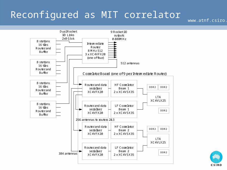
www.atnf.csiro.auReconfigured as MIT correlator
8 stations16 tiles
Router andBuffer
8 stations16 tiles
Router andBuffer
8 stations16 tiles
Router andBuffer
8 stations16 tiles
Router andBuffer
IntermediateRouter
8 MHz 5123 x XC4VFX20
(one of four)
Dual RocketI/O Links2x8 Gb/s
9 Rocket I/Ooutputs
0.888MHz
Router and dataserialiser
XC4VFX20
Router and dataserialiser
XC4VFX20
Router and dataserialiser
XC4VFX20
Router and dataserialiser
XC4VFX20
HF CorrelatorBeam 1
2 x XC4VSX35
LF CorrelatorBeam 1
2 x XC4VSX35
HF CorrelatorBeam 2
2 x XC4VSX35
LF CorrelatorBeam 2
2 x XC4VSX35
LTAXC4VLX25
DDR2
DDR2 DDR2
LTAXC4VLX25
DDR2
DDR2 DDR2
Correlator Board (one of 9 per Intermediate Router)
512 antennas
384 antennas
256 antennas to routers 2&3

www.atnf.csiro.auPost-correlation Processing
(Tim Cornwell)
Not just “off-line” software for xNTD Probably require extensive FPGA-based processing on-
line to reduce data enough for storage
Commonalities with MIT LFD
Resource budget! Anyone aware of case where
predicted effort > than actual effort?

www.atnf.csiro.auThe Panorama
Mileura means Can see a long way
www.atnf.csiro.auRFI Mission
Characterize RF Spectrum 50MHz-24GHz
High Sensitivity
Fine Temporal Resolution
Fine Frequency Resolution
All directions
Both orthogonal polarizations.
Noise source calibration
Period 1 year.
~Terabyte of data
Demonstrate application of Solar power.
Collaborate with WA Govt and Curtin Uni.
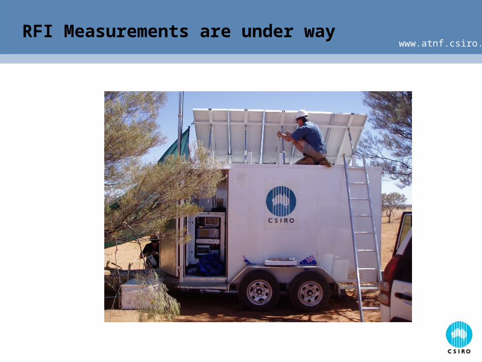
www.atnf.csiro.auRFI Measurements are under way

www.atnf.csiro.auRFI Measurements (2)

www.atnf.csiro.auNTD/xNTD Project Strategy


