51
SANDIA REPORT SAND97-0881 ● UC-122 Unlimited Release . Printed April 1997 Fiber Optic Communication in Borehole Applications R. J. France, J. R. Morgan SF2900Q(8-81)

SANDIA REPORTSAND97-0881 ● UC-122Unlimited Release
.
Printed April 1997
Fiber Optic Communication in BoreholeApplications
R. J. France, J. R. Morgan
SF2900Q(8-81)

Issued by Sandia National Laboratories, operated for the United StatesDepartment of Energy by Sandia Corporation.NOTICE: This report was prepared as an account of work sponsored by anagency of the United States Government. Neither the United States Govern-ment nor any agency thereof, nor any of their employees, nor any of theircontractors, subcontractors, or their employees, makes any warranty,express or implied, or assumes any legal liability or responsibility for theaccuracy, completeness, or usefulness of any information, apparatus, prod-uct, or process disclosed, or represents that its use would not infi-inge pri-vately owned rights. Reference herein to any specific commercial product,process, or service by trade name, trademark, manufacturer, or otherwise, doesnot necessarily constitute or imply its endorsement, recommendation,or favoring by the United States Government, any agency thereof, or any oftheir contractors or subcontractors. The views and opinions expressedherein do not necessarily state or reflect those of the United States Govern-ment, any agency thereof, or any of their contractors.
Printed in the United States of America. This report has been reproduceddirectly horn the best available copy.
Available to DOE and DOE contractors fromOffice of Scientific and Technical InformationP.O. Box 62Oak Ridge, TN 3’7831
Prices available horn (615) 576-8401, F’TS 626-8401
Available to the public fkomNational Technical Information ServiceU.S. Department of Commerce5285 Port Royal RdSpringfield, VA 22161
NTIS price codesPrinted copy: A03Microfiche copy: AOI
DistributionCategory UC-122
SAND97-0881Unlimited ReleasePrinted April 1997
Fiber Optic Communication in BoreholeApplications
R. J. Franco and J. R. MorganTelemetry Technology Development Department, 2664
Sandia National LaboratoriesP. O. Box 5800
Albuquerque, NM 87185-0987
Abstract
The Telemetry Technology Development Department (2664) have, in support of theAdvanced Geophysical Technology Department (61 14) and the Oil Recovery TechnologyPartnership, developed a fiber optic communication capability for use in boreholeapplications. This environment requires the use of packaging and component technologies tooperate at high temperature (up to 175”C) and survive rugged handling. Fiber optic wireline
technology has been developed by The Rochester Corporation under contract to SandiaNational Labs and produced a very rugged, versatile wireline cable. This development hasutilized commercial fiber optic component technologies and demonstrated their utility inextreme operating environments.
1

TABLE OF CONTENTS
I. Project Objectives hdDesign Philosophy ...........................................................................4I.l. Project Background .........................................................................................................41.2. Project Objectives ............................................................................................................4
I.3. Development Approach ...................................................................................................51.4 Fots System Ovewiew ......................................................................................................6
II. Borehole Fiberoptic Electronics Design and Test ...............................................................811.1. FOTS Electronics Design Issues ....................................................................................811,2. Selection of Fiber Optic Receivers and Transmitters .....................................................8
11.3. Temperature Testing Of Fiber Optic Trmsmitiers ......................................................lO11.4. Temperature Testing Of Fiber Optic Receivers ..........................................................l6
III. Borehole Fiber Optic System Applications .......................................................................2OIII.l. Fiber Optic Wireline Development .............................................................................2O
111.1.a. Specifications for the Rochester Wireline ............................................................2OHI.1.b Comments on the Rochester Development ...........................................................2O
111.2. Mlsr Fiber Optic Trmsmission Interface ...................................................................2l111.2.a MLSRFiber Optic Electronics Design ad Test ..................................................22111.2.bMLSWFOTS Mechanical Design .........................................................................22111.2.c MLSRField Test Operations tiththe Rochester Wireline .................................24
111.3. Crada Sowce Fiberoptic System ..............................................................................24111.3.a CRADASource FOTS Specifications .................................................................24
HI.3.b CWDASource Electronics Design ....................................................................26111.3.c. CWDASource FOTSEnviromental Testing ..................................................27
IV. References: .........................................................................................................................27Appendices ...............................................................................................................................3l
Appendix A. Fiber Optics Components Contact List .........................................................3lAppendix B. MLSRFOTS Electronics Schematics ...........................................................32Appendix C. CWDASource FOTSElectronics Schematics ............................................36Appendix D. CRADASource FOTSAltera Programming Files .......................................41
Distribution: .............................................................................................................................45
TABLE OF FIGURESFigure 1.1: Fiber Optic Transmission System F. O. T. S. .................................................................................7
Figure 11.1:Figure 11.2:Figure 11.3:Figure 11.4:Figure 11.5:Figure 11.6:Figure 11.7:
FOTS Fiber Optic Transmitter vs. Temperature Test Setup .................................................... 12
FOTS Transmitter Optical Power vs. Temperature .................................................................. 13Laser Diode TS2143 Input Current vs. Temperature ................................................................ 14
Combined Input Current Litton TX5006L & Laser Diode IRE-160 ........................................ 15
FOTS Fiber Optic Receiver Sensitivity Test Setup .................................................................... 17
Optical Receiver Sensitivity vs. Temperature ............................................................................ 18
Fiber Optic Transmitter/Receiver Pair Litton TX5006L & RX5417 ....................................... 19
Figure 111.1: FOTS Vibration Environment .....................................................................................................28
Figure 111.2: FOTS Vibration Environment ....................................................................................................29
Figure 111.3: FOTS Vibration Environment ....................................................................................................30
Figure B.1:Figure B.2:Figure B.3:Figure Cl:
Figure C.2:Figure C.3:Figure C.4:
MLSR Fiber Optics Electronics Schematic .................................................................................33
MLSR Fiber Optics Electronics Schematic .................................................................................34
MLSR Fiber Optics Electronics Schematic ................................................... ..............................35
Pelton/Sandia Interconnection Diagram for CRADA Source ...................................................37
CRADA Source PC Board Dimensions .......................................................................................38
CRADA Source Fiber Optics Schematics ...................................................................................39
CRADA Source Fiber Optics Schematics ...................................................................................40
Figure D.1.a: Altera EP-61O Design File ..........................................................................................................42
Figure D.1.b: Altera EP-61O Design File .........................................................................................................43
Figure D.1.c.: Alters EP-61O Design File .........................................................................................................44
TABLE OF TABLESTable 11.1: Optical Power Budget for MLSR (1300 nm) ...................................................................................9
Table 11.2: Optical Power Budget for CRADA Source (1300 nm) ...................................................................9
Table 111.1: Fiber Optic Wireline Specifications ..............................................................................................21
Table 111.2: MLSR/FOTS Specifications ..........................................................................................................23
Table 111.3: CRADA Source General Specifications ......................................................................................24
Table 111.4: CRADA Source Optical Specifications .........................................................................................25Table 111.5: CRADA Source Electrical Specifications .....................................................................................25
Table 111.6: CRADA Source FOTS Signal List ................................................................................................26
Table A.1: Contact List for FOTS Suppliers and Contractors .......................................................................31
3
I. Project Objectives And Design Philosophy
1
1.1. Project Background
Interest in high speed data transmission for seismic applications has a long historyand has recently elevated the interest in utilizing fiber optic technologies in this arena.Transmission of digital data over long copper lines has been heavily developed and
optimized. The upper data rate limit on copper wireline is well below 1 Mbit/sec.The high bandwidth and noise immunity of fiber optic communication systems offersclear advantages to borehole applications and could easily achieve data rates to 50Mbits/see (or more).
In a previous program, the Cross-Well Forum funded development of the Multi-LevelSeismic Receiver (MLSR) ~. 1]. The MLSR streams seismic data to the surfacewithout buffering, and thus requires a 5 Mbit/see transmission rate. This offersseveral key operational advantages to the receiver operation. The most significantbeing that down-hole memory capacity is not a recording limit and downholeprocessing requirements are minimized. Other seismic receiver applications couldbenefit from this technology and several other companies are already pursuing fiberoptic capabilities for borehole data transmission, The MLSR has been successfidlydeployed with the Chevron fiber optic wireline which was developed in the 1970s.
Another project associated vvith the Cross-Well Forum has provided an applicationfor fiber optic transmission over a wireline. The CRADA Source project has aninterest in minimizing the downhole processing electronics required to actuate thehydraulic vibrator on the CRADA Source. The high bandwidth communicationafforded by fiber optic transmission over the wireline allows the vibrator controlelectronics to be packaged in uphole controllers, minimizing the signal processingcircuitry required to operate in the high temperature downhole environment. Becausethe wireline is included in the feedback loop of the vibrator control system, widebandwidth fiber optic data transmission is required for both up and down links in thisapplication. The MLSR and CRADA Source program have driven the interest infiber optic communication in borehole applications and are the primary reason thatthe Cross-Well Forurn has encouraged funding for this development,
1.2. Project Objectives
The primary goal of this development is to demonstrate a rugged and reliable fiberoptic transmission system for operation in borehole applications. The advantages offiber optic transmission in this application are universally accepted as highlydesirable. The key problems to be addressed in this area are development and test ofoptical fibers and electro-optic components to operate up to the 175° C range.Another challenge is to develop wireline assembly techniques which protect theoptical fibers from damage due to load stress or handling. The development of apressure sealed electro-optical connector also presents a significant technical
4

challenge. These are the primary technical barriers which have slowed the adoptionof fiber optic communication in borehole applications.
The objective of this project was to develop and environmentally test the keyhardware elements of a fiber optic transmission system. The following major designgoals were established for the borehole Fiber Optic Transmission System (FOTS) :
(1) Demonstrate Electro-Optic Components in Borehole environments.
(2) Develop a commercial supplier for rugged, fiber optic wireline cable.
(3) Demonstrate Digital Communication at bit rates from 500 kbits/sec up to20 Mbits/sec.
(4) Veri& operation with bit error rates of less than 1OE-O8for operation at
175°c.
(5) Develop packing and electronics for FOTS application with the MLSRReceiver and the Cross-Well CRADA Seismic Source.
The system developed under this program generally meets all of the above goals. Adetailed set of specifications that describes the conformance of the system to thesegoals is provided in Chapter III.
1.3. Development Approach
The engineering approach used for the FOTS development was to identi~ and utilizeexisting suppliers of optical fibers, opto-electric components and wireline cable. Thisapproach allowed the development to leverage off of existing technology, whereavailable. The project resources were focused on development of the technologiesneeded for the program, but not currently available. This allowed the efficientdevelopment of a system suitable for rugged borehole applications.
In searching the market for electro-optic components for this application, we quicklyobserved that commercial suppliers will test and provide component specifications to125° C. This response is typical in high temperature electronics development andrequires the screening of suppliers and component technologies for high temperatureoperation. This screening and testing process led to the selection of Littoncomponents in the FOTS project (section 11.2). The FOTS development also reliedheavily on existing industry expertise in the wireline area. A competitive bid processled to the award of a development contract to The Rochester Corporation, allowingthem to develop a very rugged, high temperature fiber optic wireline (section III. 1).
5

1.4 FOTS System Overview
The basic elements of a fiber optic communication system are shown in Figure I. 1.
Each digital communication link in FOTS requires a dedicated optical fiber connectedwith an optical transmitter and receiver on each end of the fiber. The FOTS requiresthat the data input be a synchronous, continuous bitstream with constant bit width andno time gaps in the modulation. A companion clock is also required to convert thebitstream to a Manchester code. The output of the optical receiver must then bedecoded to recover the bitstrearn and clock for recording or processing interfaces inuphole equipment. The use of optics in these systems is limited to the long wirelinedeployment run Ili-omthe cable spool to the top of the downhole tool string (3 to 6
km). Use of fibers in interconnecting cables in downhole tool strings is attractive inseveral ways and is being considered, but this approach suffers from the excessivecost in developing and maintaining optical connectors. The downhole end of the fiberoptic wireline is terminated into a high pressure connector with both optical andelectrical contacts. The uphole end terminates in a spooling drum which is usuallydeployed on a winch truck. The use of fiber optic slip rings allows the optical signalto be passed through in the same housing which contains the electrical contactsrequired for power and other electrical signals. This eliminates the need for anyoptical processing inside the cable drum. This approach allows the optical signal to
pass all the way to the uphole signal processing area, where the fiber optic receiverwould be located. The output of the optical receiver is then decoded to recover theclock and serial bitstrearn in its original format, which can be recorded or processedby uphole equipment. The similarity in the requirements of the MLSR and CRADASource fiber systems allowed them to be based on a common design.
6

Figure 1.1: Fiber Optic Transmission System F.O.T.S
=“ieldedTwisted
Pair
\NRZ Data
Downhole_Aw MAanchest=
❑xtronics tier ~e~NRZ Uk
Line Driver ~
I ‘“ak u L-----J
Fiber
Receiver
Mounted inWhiine
Drum
+
($%&jam
& = -J+
Ring
Fiber
rreline ~
(31%%aTl)
-1 1--1Head

II. Borehole Fiber Optic Electronics Design and Test
11.1. J?OTS Electronics Design Issues
The electronic interfaces in the FOTS are simple and straight forward, based on
CMOS line driver/receiver technologies.
One key design issue to note is the need for Manchester encoding of the signals. Theoptical receivers are typically AC coupled devices which utilize high pass filtering ofthe detected signal to minimize noise. Since most digital data signals can have long
strings of one or zeroes in the stream, ‘the signal nominally requires DC response to be
transmitted. However; the Manchester code can be used to generate a signal which is
guaranteed to have a transition in every bit period. This eliminates the need for DC
response in the fiber optic receiver. Most receivers, in fact, speci~ a minimumtransmission bit rate in the region of 500 kbits/sec to 1 Mbit/see and the operatinglimit for FOTS is 500 kbits/sec.
Another design concern in FOTS is related to Positive-Emitter-Coupled-Logic(PECL) input and output stages used in the fiber optic components. The FOTSdesign allows for standard TIT_+or CMOS inputs and outputs, with level converters
included in the electronics.
Note that the FOTS electronics must survive high temperature environments. TheFOTS electronics design is based on high temperature electronics design andfabrication techniques which are docuinented in other sources [1.1].
11.2. Selection of Fiber Optic Receivers and Transmitters
Three major criterion drove the selection of fiber optic receivers and transmitters usedin the FOTS design. The first is associated with defining the optical output power
and optical input sensitivity required to transmit the optical data over cables 3 to 6 kmlong, The second is selecting components which operate at appropriate bit rates. Thethird major iwue is high temperature operation which is dealt within sections 11.3 and11.4. The bit rate issue was a bigger concern on the low end than it was on the highend. The requirement to operate, up to 20 Mbits/see was fairly easy, but the 500kbitisec lower end was close to the specification limits on many devices.
Two manufacturers \vere identified as having optical receivers and transmitters thatmeet the bandwidth requirements Litton (TX5006L and RX54 17L) and Laser DiodeInc. (TS2143 and RT2714).
The optical output po~ser and input sensitivity requirements are determined byperforming an optical power link budget. This analysis allows for cable andconnector losses to be considered in relation to the output and input power of the
electro-optical components. The optical power budgets for the MLSR and CRADASource systems are described in Tables II. 1 and 11.2.

Table 11.1: Optical Power Budget for MLSR (1300 nm)
Optical Output Power(50 micron core, 105° -17dBmc)
Optical Input Sensitivity -39 dBm
Optical Power Budget (-17 dBm - (-39 22 dBdBm))
Cable Loss (3.1 km* 2.0 dBikm) 6.2 dB
Connector Loss (3 @ 1 dB/corm) 3.0 dB
Slip Ring Insertion Loss ~2.5 dB
Link Margin (@ 105° C) 10.3 dB
Derate with Temp (175 - 105)0 C * .03 2.1 dBdB/O C
Link Margin (@ 175° C) 8.2 dB
Table 11.2: Optical Power Budget for CRADA Source (1300 nm)
Optical Output Power (50 micron core,105° -17 dBm
c)
Optical Input Sensitivity -39 dBm
Optical Power Budget (-17 dBm - (-39 22 dBdBm))
Cable Loss (6.5 km* 1.3 dB/krn) 8.5 dB
Connector Loss (3 @ 1 dB/corm) 3.odB
Slip Ring Insertion Loss 2.5 dB (Note 1)
Link Margin (@ 105° C) 8.0 dB
Temp Derating (175 - 105) 0 C * .03 dB/O 2.1 dB
cLink Margin (@ 175° C) 5.9 dB
Note 1: This specification is nominal as actual slip ring for CRADA Source design isTBD.
Consider the power budget analyses above. Note that the initial Optical PowerBudget is 22 dB and is the same for both the MLSR and CRADA Source designs.This is because the same fiber optic transmitters and receivers are used in bothdesigns. Also, it happens that the Litton and Laser Diode Inc. devices mentionedabove have nearly identical optical specifications, so they were viewed as equivalentfrom this performance point of view. Notice, also the differences in cable length andin optical loss in dB/lcm. The two wirelines are manufactured with different fibersand are different lengths. The link margins of 8.2 dB and 5.9 dB over filltemperature represent good engineering margins. The temperature deratingcoefficient of .03 dB/O C is a semiconductor property discussed in the section 11.3.The connector loss term assumes three in line connections, and uses 1 dB loss foreach, The three connections are at the optical transmitter, the optical receiver, and the
9

optical feed through on the pressure connector. Note that the insertion loss of thefiber slip ring is treated separately in both calculations. Insertion loss on optical “ST”type connectors is typically less than 0.5 dB (so, use of 1 dB is conservative).However, the optical feed through comector on a high pressure wireline connector(on the downhole end) would likely approach 1 dB.
The results of this link budget evaluation led to the conclusion that both Litton andLaser Diode Inc. devices have adequate optical and transmission characteristics to usein the FOTS design. The next section outlines the temperature performance andtesting issues which led to the selection of Litton components in the design.
11.3. Temperature Testing Of Fiber Optic Transmitters
In the process of identi~ing commercial or military qualified electro-opticcomponents to operate to 175° C, two basic types of device failures were observed.First, in the Laser Diode Inc. devices, it appears that the electrical interface circuitryfailed (at about 125° C). There was no indication that the optical elements in thecomponent failed. The second type failure was identified in the Litton devices andwas primarily a problem with high temperature electronics assembly. The Littonproblems were clearly much easier to correct, since they didn’t represent fundamentaldesign problems. Temperature testing was performed on both the Litton and LaserDiode Inc. devices to determine which was more robust with temperature. Both ofthe manufacturers carried operating specifications to 125° C for their components. Ahigh temperature printed circuit board was developed with both pairs of devicesinstalled to allow them to be tested simultaneously. The set up for the test isdescribed in Figure IL 1.
In the initial series of transmitter tests, the fiber optic attenuator was set to 1 dB lossto measure the optical output of the transmitter as a function of temperature and thereceiver was left outside the oven. The transmitter was modulated with a 5.0
Mbits/see Manchester code from the MLSR receiver system. The MLSR data streamhas checksum codes embedded in the data to allow for the detection of bit errors atthe data receiving end. The results of the transmitter tests are provided in Figures11.2,3,4,
Note from Figure 11.2, that three optical sources were tested. The Litton and LaserDiode Inc. transmitters mentioned before and a discrete LED modulated by asemiconductor switch circuit based on power MOSFETS. The LED is the IRE-160manufactured by Laser Diode Inc. The interest in testing a discrete LED was basedon the concern that the electronics switching circuitry in front of the LED mightactually fail at lower temperature than the LED. Previous experience with theMOSFET switch suggests that it will fi.mction to 200° C.
Note from Figure 11.2, that the Laser Diode Inc. devices (TS2 143 and IRE- I 60)produce higher output power initially than the Litton device. This is partially because
10

the Laser Diode devices have 62.5 micron fibers attached and the Litton device camewith a 50 micron fiber. Since the core of the fibers to be used in both MLSR and
CRADA Source are 50 micron, this apparent advantage cannot be utilized in theactual application of the system. The IRE-160 and the TX5006L degrade gracefullywith temperature, while the TS2 143 fails at 125° C. The input current for the TS2 143
(Figure 11.3.) jumps up, while the input current for the IRE-1 60 and TX5006L (Figure11.4) remains quite constant with temperature. This large fluctuation in the inputcurrent for the TS2 143 suggests that the failure in this device was in the electronicswitching circuit which modulates the LED internal to the device. Bipolar circuitstend to fail catastrophically near 125° C, so this is probably what happened here.Note the slope of the optical power derating for the other two devices is about .022 to
.028 dB/” C, which is in rough agreement with the .03 dB/” C coefficient used in thelink budget calculations. The transmitter outputs were also tested for bit errors in thistest and found to function at better than 10 E -08.
There were some packaging concerns with the Litton components. In several earlyexperiments, problems with low temperature solder and strain relief sleeving on thefiber were observed. The area of particular concern was in the method used to strainrelief the fiber where it exits the package. Another problem was observed in theepoxy bond used to attach the fiber to the LED internal to the optical components.
Since the Litton devices are packaged in metal hermetic packages, it was relativelyeasy for Litton personnel to open up the failed components and diagnose the internalpackaging problems. Sandia project personnel were able to recommend hightemperature soldering, epoxies, and sleeving ideas which allowed Litton personnel tocorrect the major packaging problems. Litton personnel were responsive andmotivated to correct these packaging issues and ultimately produced componentssuitable for operation to 175° C. It seems likely that the Litton optical transmitterscould operate up to 200° C, assuming that Litton corrected some remaining packagingissues.
11

-.
Figure 11.1:FOTS Fiber Optic Transmitter vs. Temperature Test Setup
*OVEN,~:7..>-,7- .. T::777777777T7T,
+ . . . . . . . . . . . . . . . . . . . . . . . . . . . . . . . . . . . . . . . . . . ,.,.,,
,., ., , .,.,...,’..,.,.,.. . . . . . . . . . . . . . . . . . . . . . . . .
. . . . . . . . . . . . . . . . . . . . . . . . . . . . . . . . . . . . . . . . : .,.,.,.,,
,., . . . . . . . . . . . . . . . . . . . . . . . . . . . . . . . . . . . . . . . . . . . . . .. . . . . . . .
. . . . . . . . . . . . . . . . . . . . . . . . . . . .!.,., .,.,.,.,.,.,.,.,.,.,.,...,.,...,.,., . . . . . . . . .
Sandia/OYO i:: ‘;;:;~,... Fiber ;;:; lofeet mt:... .,.,.1[i Optic ‘~jWlf=l =
‘“R /i’@@@a kco”nec’l~
Receiver j;::~~~ ;:’1 ‘iber
Formatted’Data Signal i-l
with 8 bit checksum 1-30 db
per frame. Opticai Attenuator
5 Mbits/see
nMLSR
Computer, J
Incohing Data checksums
compared to transmitted
checksum & Data displayed.
Manchester Cock

1’
0
0
. . . ---------
i
I
r----------. . . . . . . . . . . ..- .
I I I
oI
m o my c)
I
J
c
om
o0
0m
oq)
n
o
13
m,w!
C9o0m Icm1-

-.
-&
1,200
1,000
800
600
400
200
Figure 1[.3: LASER
.
—
DIODE TS2143 Input Current vs. Temperature
I I I I
oI
50 100 150 200 250Temperature (Degrees C)

--
E
400
380
360
340
320
300
Figure 11.4:Combined Input Current Litton TX5006L & Laser Diode IRE-I 60
o 50 100 150 200Temperature (Degrees C)
250

11.4. Temperature Testing Of Fiber Optic Receivers
A second series of tests were required to demonstrate that the fiber optic receiverswould fimction at temperature with the transmitters also functioning at temperature.
The setup for this test is described in Figure 11.5. Note that both the receivers and
transmitters are in the oven for this test. This was a functional test of the tworemaining fiber optic receiver candidates, having settled on the Litton TX5006L forthe transmitter. The TX5006L output was used to drive the optical inputs to theLitton RX5417L and the Laser Diode Inc. RT27 14. The optical attenuator was stillset at 1 d13for this experiment. The RT2714 receiver failed at 125° C in similarfashion as had been observed with the Laser Diode Inc. transmitter as discussed
above. The supply current increased dramatically at 125° C and the unit failedpermanently. Similar conclusions can be drawn about the failure of electronics
integrated inside the device as was discussed in the previous section in the failure ofthe Laser Diode Inc. transmitter. The Litton RX5417 operated well up to 175° C andwas chosen for use in the FOTS design.
T’he third series of tests demonstrated that the LittonRX5417L will maintain highoptical sensitivity as operating temperature increases. The optical attenuator was usedto determine the minimum optical power level required to maintain low bit error rateswhile operating at higher temperatures. The following tests were performed from 25°
C to 175° C at 25° C increments.
1. The optical components were place in the oven and allowed to stabilize tothe oven temperature.
2. The optical attenuator was set for the maximum attenuation for which thesystem would operate with no bit errors.
3. The attenuated light level was measured through the optical power meter.
In this way, the minimum optical power required for operation at bit error rate lessthan 10 E -08 was recorded and plotted against temperature. These tests were run atbit rates of 1 Mbit/see and 5 Mbits/see with the Manchester encoded data as describedabove. Figure 11.6provides the results. Note that the optical sensitivity of theRX5417L is essentially flat born ambient to 175° C. So, there is apparently nosensitivity penalty for operating the RX54 17L at these elevated temperatures, and itseems likely that the optical power analysis from section 11.2.will hold and the linkwill operate to at least 175° C. Figure 11.7 illustrates the input current of thecombined fiber optic system using the Lition RX54 17L and the TX5006L. Note thatthe currents are quite stable over the temperature range of ambient to 175° C, whichsuggests that the devices are operating normally.
16

--
4
Figure 11.5:FOTS Fiber Optic Receiver Sensitivity Test Setup
Sandia/OYOMLSR
Receiver
*OVEN
Formatted’Data Signal +& Incoming Data checksumswith 8 bit checksum 1-30 db
Optical Attenuatorcompared to transmitted
per frame.1 Mbits/see or 5 Mbits/see
checksum & Data displayed.
Manchester Code
Note: For Sensitivity Tests, both Transmitters and Receivers were in the Oven.

--
Figure 11.6:Optical Receiver Sensitivity vs. Temperature
G30
L
-38
“40
“42
-4’4
-46
-48c1
m
A-----~sL-.....-A ------------ “‘-”-”--ATA
50
* MinimumRXInput Power
for PE c= 10exp-8
100 150
Temperature (degrees C)
1Mbit/kec 5 Mbit/seem --------A4-------
200 250

--
.U3
Figure 11.7:FIBER OPTIC TRANSMITTEF?/RECEIVER PAIR Litton TX5006L & R)(54I 7
400
300
200
100
0
—
f::... f:..............f......-----------
-.::::::::*: . . ....-_l’:=:~:”””””””””.”””...’””,,z----------- “:::::::::;::::;;””””””””...~.~----------
0 50 100 150 200 250
Temperature (degrees C)
+5 volts +15 volts -15 voltsm --------A------- ●

III. Borehole Fiber Optic System Applications
111.1. Fiber Optic Wireline Development
The development of the MLSR seismic receiver created an interest in developing acommercial supplier for a high temperature fiber optic wireline. The Cross-WellForum approved a two year project, Advanced Borehole Telemet~, to pursue hightemperature fiber optic component studies and the development and production of awireline to allow fiber optic communication in borehole applications. The componenttechnology studies described in the previous section were fimded in part from theAdvanced Borehole Telemetry project with additional funding provided by theCRADA Source project. The demonstration of fiber optic wireline operation in therugged, high pressure, high temperature environment of the borehole presentssignificant technical challenges. A competitive bid process was used to identifi thesupplier of the wireline. Based on this process, a contract was awarded to TheRochester Corporation.
III. 1,a. Specifications for the Rochester Wireline
The specifications of the wireline produced and delivered by Rochester aresummarized in Table III. 1. A wireline was fabricated, tested and shipped toSandia to complete the contract and is in current use.
111.1.b Comments on the Rochester DevelopmentThe wireline and optical connector produced by Rochester is the end result ofa very challenging technical development. Sandia is very pleased with theresults of the development, which represents a significant improvement in thestate of the art of wireline development.
Rochester has significant experience in the wireline and fiber optic cablesbusiness and brought essential expertise into this program. The design of thiscable was fairly routine for Rochester in most areas. However, theprocurement and qualification of an optical fiber operating to 175° C became asignificant challenge.
Rochester identified a high temperature fiber produced by Corning, which wasselected for this design. Stress and temperature testing of the fiber to 175° Cprovided very encouraging results. The difficulties arose when Comingapplied the cladding buffer to the fiber and Rochester found “lumps” in thislayer of the fiber assembly. Rochester and Coming subsequently refined theassembly process to correct the problem and Coming ultimately delivered afiber that Rochester was able to process into the wireline.
The development of the optical termination and connector produced a robustassembly. Environmental and strength testing of the wireline assembly atRochester were successful and Sandia took delivery of the wireline in August,

1995. Detailed specifications of thewireline meavailable from The RochesterCorporation (see Appendix A). The wireline has been tested at Sandia and hasbeen integrated into field test experiments to demonstrate its capability.Section 111.2provides further information on application of the wireline withthe MLSR seismic receiver.
Table 111.1: Fiber O~tic Wireline S~ecifications
1
Weight in Air ;78 lblldl i\ Breaking Strength I 21,000 lb I
Minim& Ben: Radius “~g!,
Recommended Workirm Load 5.000 lb
Armor Resistance 1.3 W/kfi
Insulation Resistance 20,000 MW*kft
Capacitance @ 1 kHz 46 pflft
Recommended Working Load 3,900 lb
1
I Fiber Type 50/1 25 micron multi-mode (Corning)
Coating - hermetic/silicon/texel ‘-
Optical Attenuation (1300 nm) 1.0 dB/km (max, Ambient Temp)2.0 dB/km (max, Elevated Temp)
Numerical Aperture 0.2
Bandwidth -,I 400 MHz-km I,
Insertion Loss of downhole connector I 1.0 dB (max @ 1300 nm) 1
111.2. MLSR Fiber Optic Transmission Interface
The MLSR receiver was developed in conjunction with Oyo Geospace to providedhigh bandwidth, high resolution borehole instrumentation. The original developmentunit of the MLSR has been demonstrated in a variety of field experiments in recentyears. The receiver has been deployed for these experiments on the Chevron fiberoptic wireline. The MLSR receiver is the ideal application to demonstrate the fieldutility of the Rochester fiber optic wireline. The block diagram of the MLSR FOTSis similar to that shown in Figure I. 1. Note that the Manchester encoder and decoder
21

111.2.a
fimctions are not included on these electronics boards because those functions areprovided in other MLSR hardware. The specifications for the MLSR/FOTS isincluded in Table 111.2.
MLSR Fiber Optic Electronics Design and TestThe electronics required for the MLSR optical system are very simpleelectrical interface circuits used to buffer the RS-422 standard electrical inputsto drive the fiber optic transmitter inputs and receiver outputs. The downhole“Advanced Telemetry Transmitter” circuit board includes electrical inputbuffers to drive the three optical transmitters installed on the board. The IRE-
1306 is a discrete LED while the TX5006L and TS-2 143 are integrated opticaltransmitters (Schematics: Appendix B). Temperature testing demonstratedthat the TS-2 143 won’t function above 125° C and is not installed in the finaldesign. The uphole “Advanced Telemetry Receiver” circuit board is intendedto interface the optical fiber data signal to the RS-422 electrical standard. Thisboard is not intended to operate at elevated temperatures and has severalcomponents designed only for 0° to 70° C operation. This board also includesthe option to operate either of two integrated optical receivers (RX54 17L orRT-2714).
111.2.bMLSR/FOTS Mechanical DesignThe mechanical design required to package the FOTS for use with the MLSRreceiver required the addition of the “Advanced Telemetry Transmitter” circuitboard into the unit which houses the Data Formatter of the MLSR system.The MLSR data formatter housing was lengthened to accommodate thisboard, with the uphole end being modified to allow connection to theRochester opto-electrical connector.
22

Table 111.2: MLSIUFOTS Specifications
Power Requirements I 10 to 15 Vdc (275 ma)
/
\ /
Input Sign;l Code ManchesterBit Rate 0.5 to 10 Mbits/see
Signal Input Level O/5V, Differential, 200 W (RS-422 type)
Optical Output #1 Source: Litton TX5006LPower Out: -17dBm (1300 nrn)Optical Connector: “ST”
with 50 micron fiber I
Optical Output #2 Source: Laser Diode Inc. IRE- 1306-650Power Out: -15 dBm (1300 nrn)OpticalConnector: “ST” with 62.5 micron fiber
PC Board Dimensions 2.75” X 6.0” (one board)
Operating Temperature 0° to 175° c
Power Requirements
Output Signal Code!
Manchester
Bit Rate 1.0 to 10 Mbits/see
Signal Output Level O/5V, Differential (RS-422 type)
Optical Input #1 Receiver: Litton RX54 17LMin Power: -39dBm (1300 nm)Optical Connector: “ST”with 50 micron fiber
Optical Input #2 Receiver: Laser Diode Inc. RT-2714-052Min Power: -40 dBm (1300 nm)OpticalConnector: “ST” with 62.5 micron fiber
I PC Board Dimensions I 4.75” X 4.0” (one board) I
I Insertio;Loss (1300 m-n) \ 2.5 dB1
I
Number of Electrical Contacts 8
Current Rating 7 Amps (continuous)
Voltage Rating 1000 v
Slip Ring Model # Focal, Model 180/197
23
111.2.c MLSR Field Test Operations with the Rochester Wireline
After accepting delivery of the Rochester wireline, the fiber optic interfaceelectronics were assembled and tested with an MLSR. receiver package foroperation as a system. This testing was completed in September, 1995 atSandia Labs. The MLSR was found to operate with the Rochester wirelinewith bit error rates lower than 10 E -8. The wireline, slip ring, and electro-optic interface boards were then sent to Oyo Geospace in Houston to beintegrated onto a wireline truck for field test demonstrations, with BOLTTechnologies being the field operations contractor. The fiber optic wirelinewas operated in a field experiment for the Gas Research Institute inSeptember, 1995. The wirehne and fiber optic interface functioned very wellin this demonstration, and fiuther field operations are ongoing.
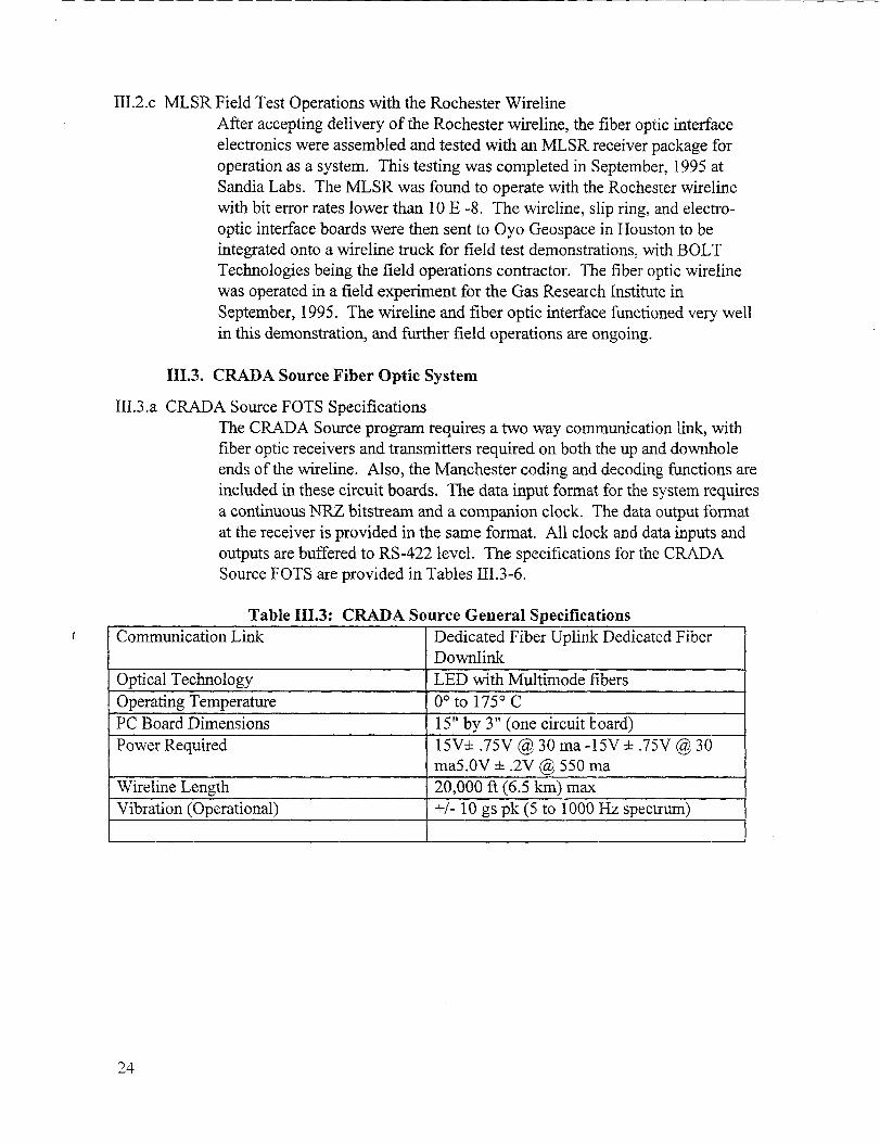
111.3. CRADA Source Fiber Optic System
111.3.a CIUDA Source FOTS Specifications
The CRADA Source program requires a two way communication link, withfiber optic receivers and transmitters required on both the up and downholeends of the wireline. Also, the Manchester coding and decoding fictions areincluded in these circuit boards. The data input format for the system requiresa continuous NRZ bitstream and a companion clock. The data output formatat the receiver is provided in the same format. All clock and data inputs andoutputs are buffered to RS-422 level. The specifications for the CRADASource FOTS are provided in Tables 111.3-6.
Table 111.3: CRADA Source General Specifications1 Communication Link Dedicated Fiber Uplink Dedicated Fiber 1
Downlink
10ptical TechnologyII LED with Multimode fibers-. !
Operating Temperature 0° to 175° c
PC Board Dimensions
==1
15“ by 3“ (one circuit board)
Power Required 15V=t .75V @ 30 ma -15V + .75V @ 30ma5.OV + .2V @ 550 ma
Wireline Length 20,000 ft (6.5 km) max
Vibration (Operational) +/- 10 gs pk (5 to 1000 Hz spectrum)
24

Table 111.4: CRADA Source O~tical Specifications
Optical Wavelength 1300 nm
Fiber Type multimode graded index core size: 50micron
Optical Transmitter Litton #TX5006LPower Out: -17 dBm
Outical Receiver Litton #RX5417Min Power: -39 dBm
;ptical Connection (both TX and RX)tI 1 meter fiber pigtail with ST connector
Table 111.5: CRADA Source Electrical Specifications
1/0 Format (See Note 1) Continuous N~ Data& SynchronousClock
1/0 Signal Transmission(See Note 2) Differential RS-422(TW0 signals one clock,one NRZ data)
Transmission Format Manchester (coding and decoding withinFOTS)
Down Link Bit Rate 1 Mbit/see (NRZ) (+/- 5’Yo)
Up Link Bit Rate 1 Mbitisec &RZ) <+/- 5%)
Decoded Clk Specs: Symmetry: 60/40 %Jitter: 0.1 % (max)
Bit Error Rate 1OE-8 (or better, fill temp)
Data Delay Circuit: 1 bit period+ 0.13 usecFiberPropagation: 33 usec (6.5 km cable)TotalDelay: 34 usec
Twisted Pair Cable WL Gore # GWN 1121-3 (or similar)
Note 1.Synchronous Clock is Continuous with rising edge at center of NRZ data bits.data can come in packets with NRZ data line idling either high or low.)
Note 2. Based on National Semiconductors: DS26C31 and DS26C32 RS422 devices.
(-mu
25
Table 111.6: CRADA Source FOTS Signal List+..&%
~::m$.$pw=’~m%~s$:”.,-+,**S:: _ ;-B@~~~B “~?:@j&y@&@*+’!ws::’”’p~rA ;-
=~-s>....@$#&<7+.*$~&$&$
RXDat’ “’”‘““”s. -?$“ ““-”.....%~v..*3. w$.u
J1.1 “ e “ ““RXDat- J1.2 Pair A; blkRXDatSh J1.3 Pair A, shieldRXClk J1.4 Pair B, whtIUKClk- J1 .5 Pair B, blkKXClkSh J1 .6 Pair B, shieldRx_out J1.7 cond #1Rx_out- J1.8 cond #2RxOutSh J1.9 cond #3Rx_Alarm J1.1O cond #4(Internal Signal) J1.11 NCRst- J1.12 cond #5Spare J2.1 NCSpare J2.2 NCTXDat J2.3 Pair C, whtTXDat- J2.4 Pair C, blkTXDatSh J2.5 Pair C, slhieldTXClk J2.6 Pair D, whtTXClk- J2.7 Pair D, blkTXClkSh J2.8 Pair D, shieldVcc J2.9 cond #6+15V J2.1O cond #7-15V J2.11 cond #8GND J2.12 cond #9
111.3.b CRADA Source Electronics Design
The development of the electronics for the CRADA Source interface is basedon very similar technologies as those discussed in section 111.2. Thefunctional block diagram is shown in Figure I. 1. Note, that since the CRADASource requires two way communication, a second uphole to downhole link isimplemented for it. Obviously, the operation of the CRADA Source requirestwo fibers: one for downhole and one for uphole communication. The keydesign issue unique to the CRADA Source FOTS is the requirement for aManchester decoder interface to operate downhole. This element of thedesign is basedonanAlteraEP-610 programmable logic device. Thesedevices were used heavily in the MLSR receiver design,, and are known tofunction up to 200° C. Further design information on the Manchesterdecoding algorithm is available in the source code design files for the EP-61 Odevice, which is further defined in Appendix D. The electronics schematicsand wiring definition for the CRADA Source FOTS are provided in Appendixc.
26

111.3.c. CR4DA Source FOTS Environmental TestingThe circuit boards for the CRADA Source have been assembled and tested to
the temperature and vibration specifications listed in Section 111.3. Thetemperature tests were completed utilizing the test setup described in Sectiorl
II. Since the CRADA Source FOTS circuit boards and components areattached to a hydraulic vibrator in the operational environment, there was
concern about the vibration survivability of the unit. All of the circuit boardsdelivered for operation on the CRADA Source were tested, fully assembled onshaker tables at Sandia Labs. The vibration environment for these tests wereapplied in all three axes, and are described in Figures II!. 1-3.
After testing at Sandi~ these FOTS circuit boards were installed and tested inthe CRADA Source electronics module being assembled and tested at E-Systems in Salt Lake City.
IV. References:
G. E. Sleefe, B. P. Engler, P. M. Drozda, R. J. France, J. R. Morgan, Development of theMulti-Level Seismic Receiver (MLSR), SAND94-21 62.
27
-.
fJm
Control
0.1
Log
g’/Hz0.01
DOF 120
RMS(g)
7.702
0.001
0.0002
11:37:27
24-JuI-1995
Test Level: 0.000dB Reference RMS: 7.702 Test Range: 20.000,2000.000 HzTest Time: 001:00:00 Clipping: 3.00 Sigma Resolution: 5.000 Hz
4
20
Log
100
Frequency (Hz)
PC BOARD (FO SOURCE) Figore 111.1: FOTS Vibration
X-AXIS S)N AO1 Environment
1000 2000
Test Name: PC_BOARD.tmp

0.1
Log
g2/Hz0.01
DOF 120
RMS(g)
7.782
0.001
0.0002
12:53:37
24-JuI-1995
--
Test Levek 0,000 dB Reference RMS: 7.702 Test Range: 20.000,2000.000 HzTest Time: 001:00:00 Clipping: 3.00 Sigma Resolution: 5.000 Hz
i
20 100 1000 2000
Log Frequency (Hz)
PC BOARD (FO SOURCE)Y-AXIS S/NAOl
Figure 111.2: FOTS VibrationEnvironment
Tesl Name: PC_BOARD.tmp
—
-?5-e/3
..,”
,..’..,’
z00
m~%L13-7R-3.--3
-+-+-C-Q

I
Appendix A. Fiber Optics Components
Table A.1: Contact List for FOTS Surmliers and Contractors
Corporation
Oyo Geospace
Bolt Technologies
Litton PolyScientificFiberOptic Products
Laser Diode Inc.
Focal TechnologiesInc.
Arnold Pater
Larry Walter
Mike Wright
751 Old Brandy Rd.Culpepper, VA22701
9777 W. Gulf BankRd. Suite 10Houston, TX77040
11220 Timber Tech.Tomball, TX77375
1213 N. MainBlacksburg, VA24060
4 Olsen Ave.Edison, NJ08820
40 Thornhill Drive,Unit 7Dartmouth,Nova ScotiaCanada
B3B 1s1
(713)849-2595
(713)784-8200
(703)953-4751
(908)549-9001
(902)468-2263

Appendix B. MLSR FOTS Electronics Schematics
Figures B. 1 through B.3 are the electronics schematics for the FOTS for the MLSR.
32

-.
a —____ I 7 T 6 I 5 I 4 1 3 I 2 I 1
Vcc Rt7
11
1 I +12V I
-L! ~30,
~.
I I2 lufd RX541 7L
CKR06 Vcc
—
~U7
RX1 OUT 1 ~ Al
JUm! 7 B 50RX2 OUT 9 c
RNc5511
SPARE- 1 15 ~01
PAD Vcc
R22 ~ :6R7 %c55
I%C55~-- =
1*2
D 6C31. 16 PIN oIP %55 Re-2 “n— RX2 BuF
R1O
A
B
c
0
@
3 RX* OUT
13 RX OUT
AA_ 13------9 AO
14SPARE-4
PAD
w-=’=-PAO
—
UrT----%l “I
2
—=—
Vcc
TVcc
us T5V OUT)!! i
1f’%’-’2v0~-. Vcco Vc-c.
(J6I 00RNC55 ‘~
1
i 1.++12V
= MDM -
–F-l=4-.
.- ”,,
15 SBSP
* NC NC +%(NC _k.306 + t:%~ !% 33ufd CKR06 Ron Franc.
2 T330-O Sand, a Nat, onal LaL. s* :2 ::; ::: *
“ -Department 2664 MS0987
w+ N8 NC + 1 Albuquerque, New Me. ,..
~ NC _ J- c406 _ 1 a7185
- NC [: ==+( 33urd C206 Title2 T330-D 2 lufd
-j-1
- 12V OUTCKR06
ADVANCED TELEMETRY RECEIVER
-12v OUT + I-12V— DR29120T
, JI:rOc”::l?:::g*8 I 7 I 6 I 5 I 4 I 3 1—
Figure B, 1: MLSR FiberOptics Electronics Schematic
--
8 I 7 I 6 I 5 I 4 i 3 I 2 I 1
..III FO DA T-1
Vcc1
R271 OK 1
19RNC55
2C104
2
T5i CIw
14
R7U4 =
RSEL VccRNC55
110 1
,; :fi ;; OUT A~ IN B-
IN B+ OUT B
: IN C-
111~- lN C+ OUT C
III
,0 IN D-FO OAT-2 IN 0+ OUT 0
77 T6 Vcc,: EN
~ EN-
LrGND
— OS26C32112
1 Fo 0.1.21 17
R6 R4RSEL RSELRNC55 RNC55
T13 —~ ,0 SHLD2(._ , ._L—
VccT
R21240
RNC55
1I ----------- ---– –,,
‘ ‘ DEFAULT.,
1,Q> = OPEN I ,
R23 . OPEN GR:: : :;&RNT ; ;
:; 1,“-—-—---— --- —----J I1––____.__.-––_ ___–
U20R22
FO DAT 9 8 1~
v RSEL54 AC14 RNC55
Vcc
T 41 011RS1306-650
IA:C55 0 11
~’!!2t-1 GS3
c1 R13Ioopf 5KCKR05 RNC55 =
2
Q21 RFF 1
Vcc
J3
+
=%T3
11
Fo OAT 1
Vcc
T
1Vc
U2A
54 AC14
+
1RI>80RNC55
$?9 21
1 27oR1o RNC55820RNC55
2
fC102
l“fd
j
1CKR05— R2
U2C = u2a100
r-.RNC55
Q?? ~Fo OAT 5 6 3 4 1 _2
10 1 27054 AC14 54 AC14 R12 RNc55
820RNC55
1 ~[ 1 ::”,dIIII
I--------11
! C211 2 T330-C It
33”fd : :QN_D_~l~~ 1,
~
112 T330-D,,= 1,
— 1; f,NOTE, JWIIPe V w,,-,, ace .,qu, ?ed , ,11 N.a Pad, for +15V and GNDl o______________ ________ ._:lL_–___ –_______ _____ ._______g
5VRG
+15V MAIN
n
~ +,5” MAIN—
Vcc
=w=-1-- 5VCC
EE42L4u TI Vcc
CASECASE
u2E
10
U2F
; ‘Gb
54AC141
.54 AC14
Vcc
L1S 2143
I +—
I Ron Franc.
AOVANCEO TEL EMETI?Y XTMR
Size ocurnent Number
B ‘-–T2664 -FO-XTNR -0131
8 r 7 1 6 I 5 Iat. . March 29, 199z, y>cet _J of 2
4 I 3 I 2 1——
Figare B.2: MLSR Fiber
Optics Electronics Schematic

--
8 I ? I 6 I 5 I 4 1 3 I 2 I 1
+15V MAIN
1 1C105
p
C1062 10ufd 2 It, fd
T330-c CKR06
.
I I2
I 0/1U5
—OUT 6
+ :;1
~
L :1: !7 R33x —:- NC 32 .4K 1x—- GIJD t2NC55
1
‘= C107
LT 1019-52 10ufd
T330-C
{
R341 OK
RNC552
&———I-T
.-k ~,oa2 I“fd
CKR06
k !
Ron F.....
Sand, . Natz.anal I_, tJSDe Pa._tment 2664Albuquerque, New Mexico
AOv ANce O TEL EMCTRv 5V REG
slZ= OC”ment Numbe, - REv
8
B
I 72664 -F O-x TM fi-001
1 600 I
! 5 I 4 Ioat, March 29.
31 ZXhs t
I 22 of 2
—— 1
Figure E3.3: MLSR Fiber
Optics Electronics Schematic

Appendix C. CRADA Source FOTS Electronics Schematics
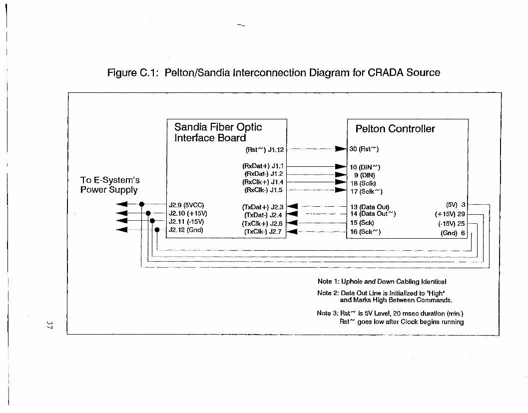
The following pages include the electronics schematics, wiring diagram, and PC boardoutline drawings for the FOTS used in the CFL4DA Source. Figure C. 1 is the wiring diagramused to wire the FOTS circuit board to the Pehon downhole vibrator circuit board. FigureC.2 is the PC board outline drawing for the FOTS circuit board. Figures C.3 and C.4 are theelectronics schematics for the FOTS used in the CRADA Source.
36
----
Figure C.1: Pelton/Sandia Interconnection Diagram for CRADA Source
To E-System’sPower Supply
~—?————
F-’-
Sandia Fiber OpticInterface Board
(Rst’”) J1.12
(RxDat+) J1.1(RxDat-) J1.2
(RxClk+) J1 .4(RxClk-) J1 .5
12.9 (5VCC) (TxDati-) J2.3I2.1O (+15V) (TxDat-) J2.412.11 (-15V) (TxClk+) J2.612.12 (Grid) (TxClk-) J2.7
I
Pelton Controller
30 (RstN)
10 (DIN’”)9 (DIN)
18 (Sclk)17 (SclkN)
13 (Data Out)14 (Data Out’”
15 (Sck)
16 (Sck’”)
(5V) 3
(+15V) 29 —
(-15V) 25 —
(Grid) 6
I I
Note 1: Uphole and Down Cabling Identical
Note 2: Data Out Line is Initialized to “High”and Marks High Between Commands.
Note 3: Rst’” is 5V Level, 20 msec duration (min.)Rst’” goes low after Clock begins running
—

If
E❑-la
mc1m
P------ =-----i
<
In<CKu
mm
a)L3
i
“3s

--
r- ‘,’3 1 4 4 5 I e I 7 I
Vcc
TVccT IT/D .7.
[
Vcc FO.RcVR
R3200
R~10K TX OAT
m DAT.RNC55 1
i ;)%,
f ~~, ‘~ + :%5
.TX OAT+TX OA1.
1/ OAT..\& =
~ TXDAT SHLO. . .~
R1w
RSEL &L Vcc
~
R1dC55 RNC55
JXD T SHL
f bl ‘--I1X CLK+TX CLK.
A,; twA.
OUT A 3
* %b’ ‘AN””
TxcLK SHLD
,5 IN A. FO_RCVR SCH,4 IN 8.
. ~ w 8. OUT, “ ,—
= 5 l—+): q--l’54ACC3 ..- .%%=4 I
Vcc+.-.-i
w%
54AC84 :3 8
S.4AC74WC
T=
‘-
II I ,; IN [
TX cl x. IN [,.
“cpki--DS26C32
B
H-;&RNC55 v’
1 I
R2410KRNC55
. .
TX Cl K. ! .
1- 1-
3.’5 u
WC
TVccT
V+c
/“ 1RI
.U2A180RNC5S I M,
~
PECL OUT
,,,1
VccT Ii
-MM WT 1 2R9
.
WC
1P
54AC14 R1o
,~
i %05 ‘%”
-MAN DurI&
SIGNAL % ;
‘-1 I a%
SIGNAL ~:: z,~
Vcc 20
1
:: ;:—. ~ 17
R2180
Vcc y
RNC55we
Vcc 14CASE GND ,3
.K .CASE GND
3 .
~L,;–———————r..fa,l~,jJL ,* .,,
‘- ‘? ----1 , s ~, ‘cc - ;;13M45,,., (, .,,
,22 ,,,.,, ,
1--- _ _..__.. :’Z._ _ / ‘ ‘D-%“”,: /_i::=’ ;,,,:,:: ;“-:,,D”0!. 13 ..,, !,,. ,,,,, ”6.,.0
Um,, -
R22:NC55 02
4,,, OUT 9 8, ...2IRFFI1O
RSEL54AC14 RNC55
i :~.$ ! %5: s:
r
RI I. ..2, 1 I *—
1-PECt OuT- . TX5W6L
27054AC14 RNC55 ‘u
—
‘54AC 14
L_.._l.
1M
R 12820RNC55 III
&cmF,amoo
Sanda Nstind Lab,WCC
I,&d 1.3 +.4
3tPMiIIIeId 2864 MS 0987 0
~wewm New M.WO17185
I ’330 1 ‘H: ‘. ‘y;
rme —
Fber OPbcsewu heed=.
2i2
lbmmmlNumb,,
7 = ~ :2
Z2u&+owrmz ,,
I I 3A03
I 4 t 5 I> ate Mdw, Febnwv 03, 1997* I
_. S“,,! I .,*
a
Figure C.3: CRADA Source!.)Fiber Optics Schematics

-.-PJk
8
I , ! 2 I 3 I 4 4 5 e I 7 I
JP1& ~2 BP
,––,%7-––– ‘ ,
I ~ 2 ‘=”SK IJUMPER
.15V +!5V “8
i~ ‘~
RNC55
-1.-
;~ M
,: D;:__J
i ~:: I;,;-1, NC
CI08B -1 u =
~ NCl~z
RX MON
‘“’ 1- —— .,.
8R54
~ VDo+tsv.
$
I
. ..”.U14
R421CKIK
0PA827 %,s L– __
RNC55 R51 . .5KRNC55 D C1$4E
‘lb =. .Irifv CKR05 “
I
.15VMl%? %%he--l 1“
+ U1lI
..,.: For .’,,”,1 opemt {’=” omit tha,a pa,,,,
.3, R50, R5!, 652, U14, CII,A. C1118, R53, C8
I ---:’:-’”: ‘:;::: --------------- .– – – – . . . – -- IVREF ; IN A-,ml,. -.
our a -
R3010K
OUT c -5
RNC55 OUT D * ‘cc
1—
os2ec32 ~ ~:~05———“’c”T WC
T.
1-Vcc
C7
*L
Wd U2F. CXR06
13 12
54,4C14R4315JKRNC55
. G——
RST PE1I
R371 RX O1lT-
V+cI
‘./%-2. .
— — — — — — —
I VccU7
Iu 0 ;NC55 R38
VCc ‘eI.. A.z RX OUT
-AwicHIN ‘ A Al ;59 RST-
MR30 RNC55
7 B B1 ~<2
JKZCI K e c
_NR2QAT 15 ~
4R3$ VCC
r
D2 ‘-
10KRNC55 ,: EN
y
I , !74, , am _
50RNC55 R46
1 ...2 RxCLK
.y “9R35
I _21 T
wEF -n
1=3; &c
TEMPHEAT-:- 1 2 SK
RNC55-iR34
50RNC55R48
RKDAT 1~1+ -,,
50RNC55
R40RxDAT- t~ m Fmixo
50RNC55 barda NAciId Labs
epwtment2884 MS0987www New MO*O
7185
-BxQNSH—ExcLKw
—tn.
FbM OPbcScuCe lntedace
u, Itiment Number0 2864.FO.lNTm ~
Figure C.4: CRADA Source
Fiber Optics Schematics

Appendix D. CRADA Source FOTS Altera Programming Files
The Manchester decoder function used on the CMDA Source FOTS is implemented in ?u1
Altera EP-6 10. The design file which defines the decoding algorithm follows as Figure D.
Note, the MDRSTFIN.SMF file is the source file used to compile the design. The
MDRSTFIN.JED file is the JEDEC standard file, which can be used to program the devicesfor use in the PC boards.
Filename: MDRSTFIN.SMF Filedate: 2/8/96 Altera Design File(Altera APLUS Compiler: SMF Rev 1.2)
Filename: MDRSTFIN.JED Filedate: 2/8/96 JEDEC Programming file
41
—

1
5
10
15
20
25
30
35
40
45
50
55
60
65
70
R. J. FrancoSandia National Labs2-8-96AEP61OBHSource Manch Decoder,File: mdrstfin.smf (rndfin50with Rst Output Added)OPTIONS: SECURITY=OFF, TURBO=OFFPART: EP61O%
Input Definitions%INPUTS: Clk@l, CapNot@Z, Rst2N@14, ManchIn@ll, ClkIn@23
%Output Definitions
%OUTPUTS: PCO@3, PCl@4, PC2@5, PC3@6, Mode@7, Charge@8
SetCo@9, ClrCo@lO, RstOut@15, ManchInR@19,ComClk@18, NRZClk@16, NRZDat@17, Stat6@20, ClkB@21, Code@22
NETWORK:
RstOut,RstOut = COIF(RstOutc,VCC)Code,Code = RORF(VCC,SetCo,ClrCo,GND,VCC)SetCo,SetCo = RORF(SetCoD,ClkB,Rst,GND,VCC)ClrCo,ClrCo = RORF(ClrCoD,ClkB,Rst,GND,VCC)ManchInR,ManchInR = RORF(ManchIn,ClkB,Rst,GND,VCC)Charge,Charge = RORF(VCC,ClrCo,Rst,GND,VCC)ClkB,ClkB = COIF(ClkIn,VCC)ComClk,ComClk = COIF(ComClkcrVCC)NRZClk,NRZClk = RORF(VCC,ComClk,Stat6,GND,VCC)Stat6,Stat6 = RORF(Stat6D,ClkB,Rst,GND,VCC)NRZDat,NRZDat = RORF(Code,NRZClk,Rst,GND,VCC)
EQUATIONS:
ClrCoD = /Mode*PC3*PC2*/PCl*/PcO;SetCoD = Mode*PC3*PC2*/PCl*/PCO:
Code*/ManchIn;Stat6D = /Code*Mode*/Pc3*PC2*P61*/PCO + cOde*/MOde*/pC3*pC2*PCl*/PCO:ComClkc = /Code*ManchIn +RstOutc = CapNot*Charge;Rst = /Rst2N;
MACHINE: BSrcDec
CLOCK: ClkCLEAR: Rst
STATES: [ Mode PC3
ResetO [ O 0
ZerolZero2Zero3Zero4Zero5Zero6Zero7Zero8Zero9ZerolOZerollZero12
[00[00[00[0 o[00[00[0 o[0 1
[0 1[01[01[0 1
Onel [ 1 00ne2 [ 1 00ne3 [ 1 00ne4 [ 1 00ne5 [ 1 0
PC2
o
000111100001
00011
Pcl
o
011001100110
01
:0
Pco
0
101‘o10101010
10101
1
1
11
1111
1
1
1
1
1I11
4’2Figure D.1.a: Altera EP-610
Desisy File

75
80
85
90
95
100
105
110
115
120
125
130
135
140
0ne6 [ 1 0110 10ne7 [10111]One8 [ 1 10000ne9 [ 1 1001 iOnelO[ll OIO 1
Onell[ll Oll 10ne12 [ 1 1100 i
Reseto:IF ManchInR THEN OnelZerol
Zerol:IF ManchInR THEN OnelZero2
Zero2:IF ManchInR THEN OnelZero3
Zero3:IF ManchInR THEN OnelZero4
Zero4:IF ManchInR THEN OnelZero5
Zero5:IF ManchInR THEN OnelZero6
Zero6:IF !4anchInRTHEN OnelZero7
Zero7:IF ManchInR THEN OnelZero8
Zero8:IF ManchInR THEN OnelZero9
Zero9:IF ManchInR THEN OnelZero10
ZeroIO:IF ManchInR THEN OnelZeroll
Zeroll:IF ManchInR THEN OnelZero12
Zero12:IF ManchInR THEN OnelZero12
Onel:
One2:
One3:
One4:
One5:
One6:
One7:
Or]e8:
IF /ManchInR THEN ZerolOne2
IF /ManchInR THEN ZerolOne3
IF /ManchInR THEN ZerolOne4
IF /ManchInR THEN Zerol0ne5
IF /ManchInR THEN ZerolOne6
IF /ManchInR THEN Zerol0ne7
IF /ManchInR THEN ZerolOne8
Figure D. 1.b: Alters EP-610Design File
43

145 IF /ManchInR THEN Zerol0ne9
One9:IF /ManchInR THEN ZerolOne10
150 OneIO:IF /ManchInR THEN ZerolOnell
Onell:IF /ManchInR THEN Zerol
155 One120ne12:
IF /ManchInR THEN ZerolOne12
160 END$
44
Figure D. l.c: Alters EP-61O
Design Fjie

Distribution:
Tad BostickWestern Atlas International
P.O. Box 1407Houston, TX 77042
Jack CaldwellGeco-Prakla2500, 801- 6th Avenue S.W.Calgary, Alberta, CANADA T2P 3W2
Mark CasadyVastar Resources
15375 Memorial DriveHouston, TX 77079
Sen ChenExxon Production Research Co.P. O. BOX 2189Houston, TX 77479
Dale CoxConoco, Inc.P. O. BOX 1267Ponca City, OK 74602-1267
I
Steve CrarySchlurnberger300 Schlumberger DriveSugarland, TX 77478
Alex B. CrawleyU. S. Department of EnergyP. 0, BOX 1398Bartlesville, OK 74005
Paul CunninghamMobil Exploration & Producing TechCenterP. O. BOX650232Dallas, TX 75265-0232
Dave DeMartiniShell Development CorporationP. O. BOX481Houston, TX 77001-0481
Tim FasnachtGas Research Institute8600 West Bryn Mawr AvenueChicago, IL 60631
Robert S. Fleming, Jr.
Oryx Energy CompanyP. O. BOX2880Dallas, TX 75221-2880
Hugh D. GuthrieSenior Technical AdvisorFederal Energy Technology CenterP. O. Box 880, MSB06Morgantown, W 26507-0880
Bob A. HardageBureau of Economic GeologyUniversity Station, Box XAustin, TX 78713-8924
Jerry M. HarrisStanford UniversityDepartment of GeophysicsMitchell Building, MS-221 5Stanford, CA 94305-2215
Robert HemingManager, Strategic ResearchChevron Petroleum Technology Corp.2811 Hayes RoadHouston, TX 77082
Donald L. HewlettTexaco Inc.3901 BriarparkHouston, TX 77042
45

John HuffordPhillips Petroleum Company1110 Plaza Office BuildingBartlesville, OK 74004
Charles A. KomarProduct Manager - Natural GasUpstream E&P
Federal Energy Technology CenterP.O. Box 880Morgantown, WV 26507-0880
Robert T. LanganStaff GeophysicistChevron Petroleum TechnologyCompanyP.O. BOX 446
La Habra, CA 90633-0446
William F. LawsonFuel Resources DivisionFederal Energy Technology CenterP.O. Box 880Morgantown, WV 26507-0880
Robert E. LemmonU. S. Department of EnergyBartlesville Project OfficeP. 0, Box 1398Bartlesville, OK 74005
Bailey LindseyGeospace Corporation7334 N. Gessner RoadHouston, TX 77040
Craig LippusGeometries Inc.
P. O. Box 497Sunnyvale, CA 94089
Kenneth D. Mahrer
Wulf MassellE & P Imaging Corp. (EPIC)1221 Lamar, Suite 605Houston, TX 77010-3037
Mark MathisenMobil Research & Development Co,P. O. BOX 819047Dallas, TX 75381-9047
Larry MatthewsCanadian HunterSuite 2000, 605 5th Avenue, SWCalgary, Alberta, CANADA T2P 3H5
Frank McCaffery
Chevron Petroleum Technology Co,P. O. BOX 446La Habra, CA 90633-0446
Danny R. MeltonTexaco Group, Inc.P. O. Box 770070Houston, TX 77215-0070
John MinearHalliburton Logging Services, Inc.P. O. BOX 42800Houston, TX 77242
Keith R. MorleyCGG American Services, Inc.2500 Wilcrest, Suite 200Houston, TX 77042
Bjorn N. P. PaulssonPresidentPaulsson Geophysical Services, Inc.1300 Beach Blvd.La Habra, CA 90633-0446
Integrated Petroleum Technologies, Inc.1536 Cole Boulevard, Suite 320Golden, CO 80401
46

Wayne D. BenningtonMichigan Technological UniversityDept. of Geological Engineering1400 Townsend DriveHoughton, MI 49931-1295
Steve PetersonMarathon Oil CompanyP. O. BOX3128Houston, TX 77253-3128
William E. PreegVice PresidentSchlumberger8311 North RR 620Austin, TX 78726
Maynard RedekerOryx Energy CompanyP. O. BOX 830936Richardson, TX 75083-0936
John B. Sinton
Conoco, Inc.P. O. BOX 1267Ponca City, OK 74602-1267/
Bill SpurgeonKerr-McGee CorporationTechnology CenterP. O. BOX 25861Oklahoma City, OK 73125
George StosurU. S. Department of EnergyFE-33, FORSWashington, DC 20545
Manik TalwaniHouston Advanced Research Center4800 Research Forest DriveThe Woodlands, TX 77381
Henry TanAmoco Production CompanyP. O. BOX3385Tulsa, OK 74102
Roger TurpeningMassachusetts Institute of TechnologyEarth Resources Laboratory
42 Carleton StreetCambridge, MA 02142
Walter R. TurpeningReservoir Imaging, Inc.13003 Murphy Road, Suite D-1Stafford, TX 77477
Sandra L. WaisleyU. S. Department of EnergyFE-32 FORSWashington, DC 20585
Skip WaldenUnocal Corporation14141 Southwest FreewaySugar Land, TX 77478
John WalshSchlumberger Well Services1325 S. Dairy Ashford, Suite 350Houston, TX 77077
Larry A. WalterBolt Technology Corporation3024 Rogerdale RoadHouston, TX 77042
Ron WardLouisiana Land & Exploration Co.P. O. BOX 60350New Orleans, LA 70160
47

Thomas C. WessonDirector
U. S. Department of EnergyP. O. BOX 1398Bartlesville, OK 74005
Graham A. WinbowExxon Production Research Co.P. O. Box 2189Houston, TX 77252-2189
Robert WithersARCO Expl. & Prod. Technology2300 W, Piano ParkwayPiano, TX 75075
E. J. WitterholtBP ExplorationP. 0, BOX 4587Houston, TX 77210-4587
Dan WOO
Mark Products10502 Fallstone RoadHouston, TX 77099
/Allen N. GolandBrookhaven National Laboratory
- Dept. of Applied ScienceP. O. BOX 5000, Bldg. 815Upton, NY 11973-5000
Norman E. GoldsteinLawrence Berkeley LaboratoryEarth Sciences Division, MS 90/1 1161 Cyclotron RoadBerkeley, CA 94720
Bob HanoldLos Alamos National LaboratoryP. O. BOX 1663, MSD446Los Alamos, NM 87545
Richard E. RiceIdaho National Engineering LaboratoryP. O. BOX 1625 MS-371OIdaho Falls, ID 83415-3710
Bernard F. Saffell, Jr.Senior Program ManagerPacific Northwest National LaboratoryP.O. BOX 999, MS-K5-22Richland, WA 99352
David Schmalzer
Argonne National Laboratory955 L’Enfant Plaza, SW, Suite 6000Washington, DC 20024
T. W, “Tom” Schmidt
Oak Ridge National LaboratoryP. O. BOX2008MS6273, Bldg. 4500 N.Oak Ridge, TN 37831-6273
Bob WhitsettLawrence Livermore National LaboratoryP. O. BOX 808, MS L-644Liverrnore, CA 94550
Frank L. BernhardRaytheon Aircrafi2268 S. 3270 W.Salt Lake City, UT, 84119
Jack H. ColeUniversity of ArkansasDept. of Mechanical EngrMechanical Engineering Bldg.Fayetteville, AR 72701
John A. GilesPelton1500 N. WaverlyPonca City, OK 74602
48

Glenn KirkendallRaytheon Aircraft
2268 S. 3270 W.
Salt Lake City, UT, 84119
Frank KissingerTeledyne GeotechP.O. BOX 469007Garland, TX 75046-9007
John A. McDonald
University of HoustonAllied Geophysics LabAGL BuildingHouston, TX 77204-4231
Bob SmithersCircuit ConceptsRoute 3, Box 45Alvin, TX 77511
J. M. CobbThe Rochester Corporation751 Old Brandy Rd.Culpepper, VA 22701
Arnold PaterOyo Geospace9777 W. Gulf Bank Rd., Suite 10Houston, TX 77040
Larry WalkerBolt Technologies11220 Timber TechTomball, TX 77375
Sandia Internal:
MS 0655
MS 0701MS 0705MS 0705MS 0705MS 0705
MS 0705MS 0705MS 0706
MS 0843MS 0979MS 0985MS 0987MS 0987MS 0987
MS 1425MS 1425MS 9018
Preston B. Herrington,5736Richard W. Lynch,6100Bruce P. Engler, 6116Gregory J.Elbring,6116Marianne C.Walck,6116Norman R, Warpinski,6116Patrick M.Drozda,6116Robert P. Cutler,6116David A. Northrop,6112(lo)Gerard E. Sleefe, 9136Larry S. Walker, 5704John H. Stichman, 2600David E. Ryerson, 2664Jeffrey R. Morgan, 2664Ronald J. France, 2664(lo)Marion W. Scott, 1307Michael A. Butler, 1315Central Tech. Files, 8523-2
MS 0899 Technical Library, 13414 (5)MS 0619 Technical Publications,
12613MS 0100 Document Processing for
DOE/OSTI, 7613-2 (2)
49


