41
Michigan Department of Transportation Field Manual for Concrete Anchoring Prepared by 1st Edition February 2015
| Date post: | 20-Dec-2016 |
| Category: |
Documents |
| Upload: | trinhnguyet |
| View: | 232 times |
| Download: | 0 times |

Michigan Department of Transportation
Field Manual for Concrete Anchoring
Prepared by
1st Edition February 2015

Engineering Manual Preamble
This manual provides guidance to administrative, engineering, and technical staff. Engineering practice requires that professionals use a combination of technical skills and judgment in decision making. Engineering judgment is necessary to allow decisions to account for unique site-specific conditions and considerations to provide high quality products, within budget, and to protect the public health, safety, and welfare. This manual provides the general operational guidelines; however, it is understood that adaptation, adjustments, and deviations are sometimes necessary. Innovation is a key foundational element to advance the state of engineering practice and develop more effective and efficient engineering solutions and materials. As such, it is essential that our engineering manuals provide a vehicle to promote, pilot, or implement technologies or practices that provide efficiencies and quality products, while maintaining the safety, health, and welfare of the public. It is expected when making significant or impactful deviations from the technical information from these guidance materials, that reasonable consultations with experts, technical committees, and/or policy setting bodies occur prior to actions within the timeframes allowed. It is also expected that these consultations will eliminate any potential conflicts of interest, perceived or otherwise. MDOT Leadership is committed to a culture of innovation to optimize engineering solutions.
The National Society of Professional Engineers Code of Ethics for Engineering is founded on six fundamental canons. Those canons are provided below.
Engineers, in the fulfillment of their professional duties, shall:
1. Hold paramount the safety, health, and welfare of the public. 2. Perform Services only in areas of their competence. 3. Issue public statement only in an objective and truthful manner. 4. Act for each employer or client as faithful agents or trustees. 5. Avoid deceptive acts. 6. Conduct themselves honorably, reasonably, ethically and lawfully so as to enhance the
honor, reputation, and usefulness of the profession.

2 Field Manual for Concrete Anchoring
Table of ContentsIntroduction and Purpose .......................................................................................... 3Part I: General .............................................................................................................. 4 Types of Anchors ............................................................................................ 4 Pros and Cons ................................................................................................. 8 Plans and Specifications ................................................................................ 9 Design Methodology and Failure Modes ..................................................11Part II: Structural Adhesive Anchoring Systems ..................................................16 Types ............................................................................................................16 Installation.....................................................................................................17 Acceptance Testing .......................................................................................20 Proof Testing ....................................................................................20 Field Testing .....................................................................................20 Equipment and Methods ................................................................21 Important Testing Notes .................................................................27 Inspection Checklist ....................................................................................28Part III: Structural Mechanical Anchoring Systems ...........................................29 Types ............................................................................................................29 Installation.....................................................................................................30 Acceptance Testing .......................................................................................31 Proof Testing ....................................................................................31 Field Testing .....................................................................................31 Equipment and Methods ................................................................32 Important Testing Notes .................................................................35 Inspection Checklist ....................................................................................36Part IV: Lane Ties and Concrete Pavement Anchoring .......................................37Appendix A: Required Loads for Proof Tests and Field Tests of Structural Anchoring Systems .........................................................38Appendix B: MDOT Form 1928 (Adhesive Anchoring System Proof Test) ................................................................39Appendix C: MDOT Form 1927 (Mechanical Anchoring System Proof Test) ............................................................40
Field Manual for Concrete Anchoring 3
Introduction and PurposeThe purpose of this field manual is to provide an overview of the structural anchoring systems the Michigan Department of Transportation (MDOT) uses for attaching to hardened concrete. These systems provide the ability to post-install attachments or anchor reinforcing bar to existing structures in order to perform the following types of work:n Widening bridges;n Replacing bridge barrier on an existing deck;n Attaching bridge mounted signs;n Installing bridge bearing anchor bolts; andn Lane ties and concrete pavement anchoring.
It is important to think of everything that goes into installing a structural anchor as part of a system. These systems are used to resist substantial structural loads and their performance is extremely dependent on proper installation. For the system to work as designed, the correct product must be used with the correct tools, installation procedures, and testing procedures; specifically per the manufacturer’s instructions as amended by MDOT specifications. In general, a cast in place anchor is superior to a post-installed anchor; however, in many cases a properly installed struc-tural anchoring system can be used to replace an anchor that has been cast in concrete incorrectly or was omitted.
This manual is divided into the following four parts: n General;n Structural adhesive anchoring systems;n Structural mechanical anchoring systems; andn Lane ties and concrete pavement anchoring (non-structural).
Contact MDOT Bridge Field Services for questions or support related to structural anchoring systems.
4 Field Manual for Concrete Anchoring
Part I: GeneralTYPES OF ANCHORSStructural anchoring systems can be divided into two types, adhesive and mechanical, and within each type there are several subtypes. Adhesive anchors can include different chemical elements, compounds, fine aggregate or other inert fillers, and may be packaged in bulk or single application sizes, while mechanical anchors include expansion anchors and undercut anchors.
All adhesive anchoring systems transfer load from the anchor into the concrete through bond strength of the adhesive, while most mechanical anchors transfer load through friction between the concrete and the expanded portion of the anchor. Undercut anchors transfer load through bearing of the bottom of the anchor onto concrete, although the department does not currently have any undercut anchors approved for use in the MDOT Materials Source Guide (MSG). Undercut anchors or other anchor types not listed on the QPL may be covered by a project special provision.
While many anchoring systems have similarities in their installation procedures, most have product specific instructions or product specific tools. For example, some anchoring systems require a special drill bit, while some mechanical anchoring systems require a unique tool to properly set the anchor. Examples of these different types of anchoring systems can be seen in Figures 1-7 on the following pages. Parts II and III of this manual cover the different systems and their installation procedures in more detail.

Field Manual for Concrete Anchoring 5
Figure 1. Adhesive anchoring system, two component epoxy type.
Figure 2. Instructions and nozzle (with extension) packaged with epoxy.

6 Field Manual for Concrete Anchoring
Figure 3. Adhesive anchoring system, capsule type.
Figure 4. Mechanical anchoring systems, expansion wedge type.
Field Manual for Concrete Anchoring 7
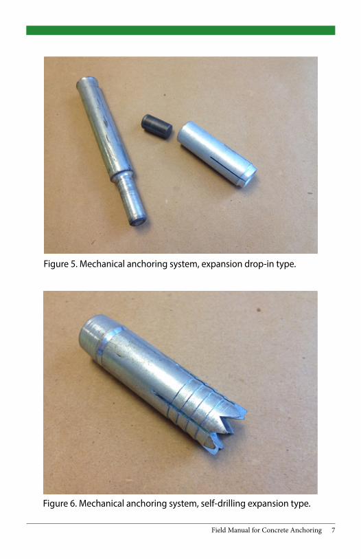
Figure 5. Mechanical anchoring system, expansion drop-in type.
Figure 6. Mechanical anchoring system, self-drilling expansion type.

8 Field Manual for Concrete Anchoring
Figure 7. Mechanical anchoring system, undercut type.
PROS AND CONSAdhesive and mechanical anchoring systems have their advantages and disadvantages as shown in the table below.
Table 1. Advantages and disadvantages of anchoring systems.
Pros Cons
Adhesive
Higher strength/ displacement ratio
Cannot be loaded until adhesive cures
Can be used with reinforcing bar
Sensitive to temperature and limited shelf life
Mechanical
Can be loaded immediately
Sensitive to hole dimensions and vibrations
Unlimited shelf life and no temperature concerns Requires special tools

Field Manual for Concrete Anchoring 9
In most cases the department’s preference is for adhesive anchoring systems over mechanical anchoring systems which is reflected in most of MDOT’s details, guides, manuals, and standards. Mechanical anchoring systems have been found to be more sensitive to installation procedures and do not perform as well in-service as adhesive anchoring systems.
PLANS AND SPECIFICATIONSThe type of anchoring system (adhesive vs. mechanical), diameter of the anchor, the embedment depth, and the hole diameter should all be shown on the design plans (hole diameter may change slightly depending on the particular product chosen). Only anchoring systems on the MDOT Qualified Products List (QPL) may be used, unless otherwise specified or approved by the Engineer. Sections 712.03J and 712.03K of the QPL list the currently approved adhesive and mechanical anchoring systems, respectively. If a product is not listed on the QPL but the contractor or supplier is claiming it was approved, it may be listed as a pending QPL update on the MDOT web page for the Materials Source Guide. In this case, the manufacturer will have a recently issued approval letter from the department.
The basic requirements for installing adhesive and mechanical anchoring systems are listed in 712.03J and 712.03K, respectively, of the MDOT 2012 Standard Specifications for Construction (SSC). While each anchoring system may have unique aspects for installation and the manufacturer’s procedures should be followed, MDOT specifications govern where there is conflict. The following are examples of how a manufacturer’s specifica-tions may conflict with MDOT specifications:n A manufacturer may state that their product can be installed at
35 degrees Fahrenheit (F) or lower, but MDOT requires a temperature of 50 degrees F and rising, which applies not only to ambient temperature but to the concrete temperature as well (section 712.03J of the SSC).

10 Field Manual for Concrete Anchoring
n A manufacturer may state that their product can be installed in damp or wet holes, but MDOT requires the hole to be dry (712.03J.1 of the SSC).
n A manufacturer may state that an embedment depth of six times the anchor rod/bar diameter can be used, but MDOT requires a minimum embedment depth of nine times the diameter of threaded rod, or twelve times the diameter for reinforcing bar (section 7.06.02B of the MDOT Bridge Design Manual).
The following list includes some of the common manufacturer equip-ment and procedures that can vary from one manufacturer to another or one product to another. Because of the variation it is important that the manufacturer’s recommendations be reviewed by the contractor and the inspector prior to installation.
Adhesive Anchoring Systems
Drill Bit. Some manufacturers require the use of a special drill bit, while some may allow a core bit.
Hole Diameter. Typical required hole diameter is 1/16 - 3/16 inch greater than the anchor bolt or nominal reinforcing bar diameter. The wrong size hole can significantly reduce capacity.
Cleaning. Some manufacturers may require specific tools and steps to clean the holes, while some may require compressed air.
Nozzles. Each product has its own mixing nozzle that was designed specifically to mix the components of that particular product; only use nozzles that come with the product.
Cure Time. All adhesives have specific cure times that are temperature dependent.
Field Manual for Concrete Anchoring 11
Mechanical Anchoring Systems
Drill Bit. See above.
Hole Diameter. See above.
Cleaning. See above.
Torque Wrench. Some manufacturers require a torque wrench to properly set the expansion element at the base of the anchor. Torque wrenches should be calibrated to ensure they are functioning properly.
Setting Tools. Some manufacturers require the use of special tools to set the anchor before loading it.
DESIGN METHODOLOGY AND FAILURE MODESThe design of anchoring systems depends on variables including embed-ment depth, anchor spacing, edge distance, concrete strength, anchor steel type, and direction of loading. The basic premise is to ensure that the connection to the concrete, whether through bond, friction, or bearing, does not fail before the anchor steel begins to yield; this provides for a ductile failure with some warning.
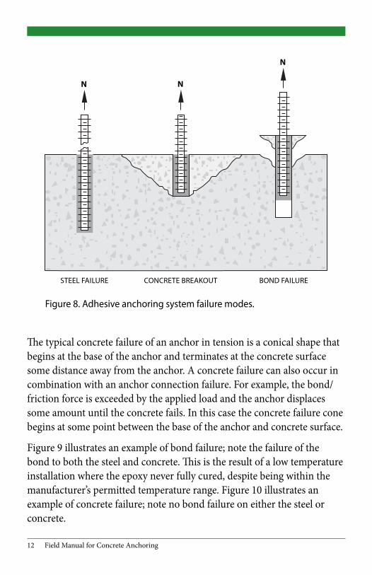
There are three basic failure modes for both adhesive and mechanical anchoring systems (see below in Figure 8):
n Failure of the anchor steel;n Concrete (breakout) failure; andn Anchor connection failure (adhesive bond or mechanical friction).
12 Field Manual for Concrete Anchoring
Figure 8. Adhesive anchoring system failure modes.
The typical concrete failure of an anchor in tension is a conical shape that begins at the base of the anchor and terminates at the concrete surface some distance away from the anchor. A concrete failure can also occur in combination with an anchor connection failure. For example, the bond/friction force is exceeded by the applied load and the anchor displaces some amount until the concrete fails. In this case the concrete failure cone begins at some point between the base of the anchor and concrete surface.
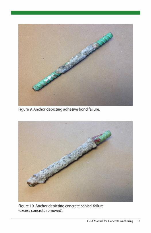
Figure 9 illustrates an example of bond failure; note the failure of the bond to both the steel and concrete. This is the result of a low temperature installation where the epoxy never fully cured, despite being within the manufacturer’s permitted temperature range. Figure 10 illustrates an example of concrete failure; note no bond failure on either the steel or concrete.
N N
N
STEEL FAILURE CONCRETE BREAKOUT BOND FAILURE
Field Manual for Concrete Anchoring 13
Figure 9. Anchor depicting adhesive bond failure.
Figure 10. Anchor depicting concrete conical failure (excess concrete removed).

14 Field Manual for Concrete Anchoring
The capacity of an adhesive anchor is reduced when an edge (break in the surface) or other loaded anchors are near the theoretical concrete failure cone of the anchor. This is incorporated into the design of the system through reduction factors for edge distance and anchor spacing, which vary depending on the anchor system. Figure 11 illustrates the approximate concrete conical failure of one anchor of a two anchor system superimposed on the photograph. Superimposing the approximate concrete conical failure of the second anchor on the first, as shown in Figure 12, shows the overlapping cones that lead to a reduction in capacity compared to the strength of two separate and independent anchors. Note that in both cases the edge distance encroaches on the failure cones and acts to further reduce the capacity. Edge distance can be a vertical drop or a gradual elevation change. They both have a negative effect on the pullout capacity of the anchor.
Figure 11. Approximate failure cone of the anchor on the right.

Field Manual for Concrete Anchoring 15
Figure 12. Approximate overlapping failure cones, resulting in reduced capacity of each anchor.
The department’s minimum embedment depths for adhesive anchor systems were developed based on extensive testing of the products on the QPL. Although many manufacturers provide allowances for shallower embedment depths, MDOT retains its minimum embedment depth requirements to ensure any product from the QPL be able to develop 125 percent of the yield strength of an ASTM A307 threaded bar and an ASTM A615 or A996 Grade 60 bar reinforcement, at embedment depths of nine times the diameter and 12 times the diameter, respectively.
Table 2. Minimum Adhesive Anchor System Embedment Requirements
Anchor Type Minimum Embedment
ASTM A307 threaded bar (36 ksi) 9 x bar diameter
ASTM A615 or A996 bar reinforcement (60 ksi) 12 x bar diameter

16 Field Manual for Concrete Anchoring
For mechanical anchoring systems, some manufacturers list multiple permitted embedment depths. For these cases, the minimum embedment depth MDOT allows is listed on the QPL, when applicable.
Part II: Structural Adhesive Anchoring SystemsAdhesive anchor is a general term implying the use of one of the various adhesives used to bond anchors to hardened concrete. Subsection 712.03J of the current edition of the QPL for structural adhesive anchoring systems includes epoxy adhesives, methacrylates, urethane-methacrylates, and cementitious grout. With all of these systems the hole diameter, depth, cleanliness, and proper adhesive mixing are critical to achieving the design strength of the system. The manufacturer’s recommendations should be followed unless they conflict with MDOT specifications in which case MDOT specifications govern.
NOTE: MDOT has a moratorium on adhesive anchors placed in sustained tensile applications due to the possibility of creep failure; overhead installation is not permitted. Multiple ceiling panel failures using overhead adhesive anchors occurred after the I-93 ‘Big Dig’ project in Boston, MA. Creep of the adhesive was found to be a major contributing factor.
TYPESTwo-Part Epoxy Adhesives. The most common type of adhesive anchor-ing system is shown in Figure 1, although the component ratios can vary between products. They can achieve final cure in anywhere from one hour to 48 hours depending on temperature and the specific components used. The viscosity of epoxy adhesives can vary widely.
Methacrylate Adhesives. Similar to epoxy adhesives in that they are two-part systems that must be thoroughly mixed. These types typically have shorter curing times than most epoxies.
Field Manual for Concrete Anchoring 17
Capsules. As shown in Figure 3, capsules eliminate the need for a dispens-ing system or mixing nozzles, but do require special threaded rods with a beveled end to rupture and mix the capsule in the hole. Capsules require a special drill attachment as well.
Cementitious Grouts. Although there is only one cementitious grout cur-rently on the QPL it is used frequently on department projects. The neces-sary hole diameter is larger than that of epoxy or methacrylate adhesives, and due to low viscosity, cannot be used in horizontal applications.
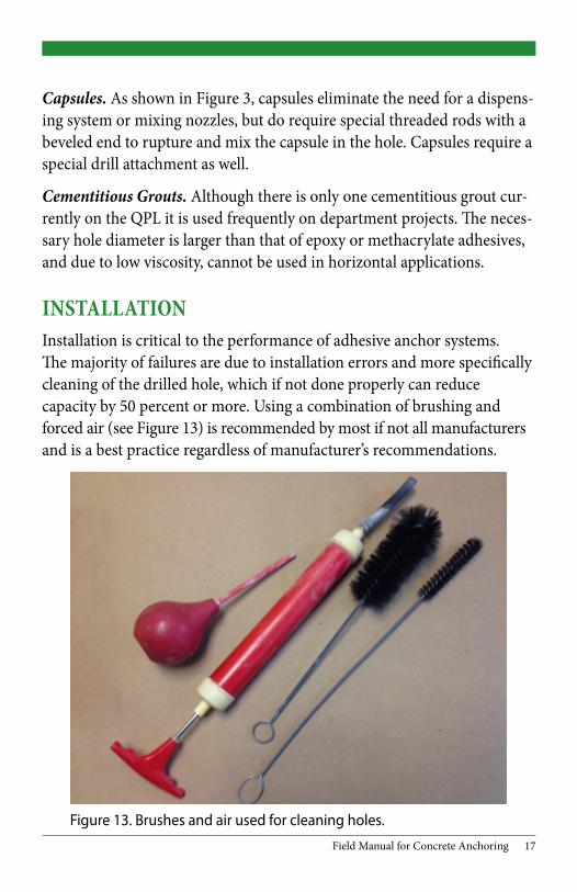
INSTALLATIONInstallation is critical to the performance of adhesive anchor systems. The majority of failures are due to installation errors and more specifically cleaning of the drilled hole, which if not done properly can reduce capacity by 50 percent or more. Using a combination of brushing and forced air (see Figure 13) is recommended by most if not all manufacturers and is a best practice regardless of manufacturer’s recommendations.
Figure 13. Brushes and air used for cleaning holes.

18 Field Manual for Concrete Anchoring
Precautions should be taken to ensure drilled holes are perpendicular to the surface of the concrete. Edge spalls or other damage at the surface of the drilled holes should be completely filled in with adhesive. If during drilling, existing reinforcement is encountered, contact the Engineer to determine how far a new hole can be drilled from the original hole and how that will impact the attachment. Per section 712.03J.1 of the SSC, the contractor is to “Propose a method that does not cut or damage existing reinforcing steel”. In most cases a pachometer (Figure 14), steel cover meter or Ground Penetrating Radar (GPR), as seen in Figure 15, can be used to locate existing reinforcement prior to drilling.
Figure 14. Pachometer used for locating bar reinforcement.

Field Manual for Concrete Anchoring 19
Figure 15. GPR used for locating bar reinforcement.
Proper mixing of the adhesive is critical. The nozzles that are provided with the adhesive must be used and the components must be thoroughly mixed before they are injected in the hole. Therefore, when a new sup-ply (cartridge) of adhesive is used the portion at the beginning must be discarded and not placed in the hole until the product exiting the nozzle is completely homogeneous and the individual components cannot be de-tected. After thoroughly mixing the adhesive, the tip of the nozzle should be placed at the bottom of the hole and slowly drawn out as the adhesive is injected. Extensions can be placed on the nozzles (see Figure 2) for narrow and/or deep holes.
After filling the hole with adhesive, the anchor should be placed with a twisting motion as it is pushed downward to help distribute the adhesive around the bar and eliminate trapped air. If adhesive is not observed to overflow the hole after the anchor has been placed, it must be removed and re-installed. The gel time or working time, and the final cure time must be observed, based on the current temperature.

20 Field Manual for Concrete Anchoring
ACCEPTANCE TESTINGAll adhesives go through a rigorous review and testing process in order to be placed on the QPL. Regardless of QPL status, all anchoring systems must undergo additional testing in the field on a per project basis in the form of proof testing and field testing, to address different aspects of performance and consistency.
Proof Testing (section 712.03J.1 of the SSC). Three anchors, representative of anchors to be installed on the project, are installed by the contractor on a separate concrete block and tested by the Engineer. Anchors for proof testing should be placed such that edge distance or spacing does not reduce capacity. They must develop 125 percent of the yield strength of the bar with less than 1/16 inch of slip. Once a product is placed on the QPL it is not retested for QPL acceptance unless performance concerns have been noted. Over time the formulation of products on the QPL and various chemicals and their suppliers may change. Therefore the proof testing en-sures that the product is still capable of developing the same capacity as it did when it was added to the QPL. Proof testing also verifies the contractor can correctly install anchors before doing so on the permanent structure.
Field Testing (section 712.03J.2 of the SSC). During the first day of production anchoring, the contractor conducts field testing at three loca-tions selected by the Engineer. The Engineer must be notified and given opportunity to witness the testing. The Engineer may conduct additional random field tests if desired. Field tested anchors must develop 90 percent of the yield strength of the bar with less than 1/16 inch of slip. The intent of field testing is to verify that the contractor is correctly installing anchors during production and that is the rationale for randomly selecting the anchors for field testing.
Per MDOT specifications, all testing must be conducted using an un-confined tension testing device that has been properly calibrated within the last year or as needed. An unconfined tension testing device bears on the concrete away from the anchor so that the concrete is not restrained

Field Manual for Concrete Anchoring 21
around the anchor. This allows all failure modes to be tested. A confined tension testing device bears on the concrete directly surrounding the anchor and can prevent the concrete conical failure from occurring. Confined tension testing devices are not permitted. See Figure 16 for an example of an unconfined tension testing device. Note the legs on the load frame which are adjustable to allow placement as far from the anchor as possible. The hydraulic hollow core ram placed directly on the concrete around the bar without the load frame would represent a confined tension testing device, which is not permitted.
Figure 16. Unconfined tension testing device with complete testing kit.
Figure 16 shows a complete anchor testing kit which includes the following.n Load frame with adjustable legs;n Hollow core hydraulic ram;n Hydraulic pump;n Dial-indicator with mounting block; n Calibration sheet;n Set of jaws for testing rebar; andn Nuts and washers for testing threaded bars.
22 Field Manual for Concrete Anchoring
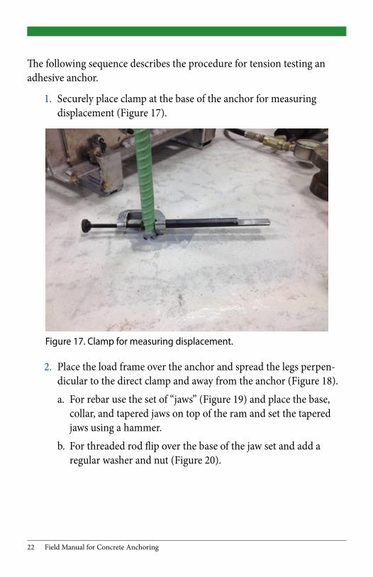
The following sequence describes the procedure for tension testing an adhesive anchor.
1. Securely place clamp at the base of the anchor for measuring displacement (Figure 17).
2. Place the load frame over the anchor and spread the legs perpen-dicular to the direct clamp and away from the anchor (Figure 18).
a. For rebar use the set of “jaws” (Figure 19) and place the base, collar, and tapered jaws on top of the ram and set the tapered jaws using a hammer.
b. For threaded rod flip over the base of the jaw set and add a regular washer and nut (Figure 20).
Figure 17. Clamp for measuring displacement.

Field Manual for Concrete Anchoring 23
Figure 18. Load Frame for testing rebar.
Figure 19. Set of jaws for testing rebar.

24 Field Manual for Concrete Anchoring
Figure 20. For testing threaded rod.
3. Securely mount the dial indicator to a steel block using a magne-tized connector or a clamping system. (Figure 21).
Figure 21. Dial indicator set to zero when in contact with clamp.

Field Manual for Concrete Anchoring 25
4. Using the hydraulic pump apply even steady pressure to the ram while checking the displacement (1/16 equals 0.0625). The calibra-tion sheet is used to equate the gage pressure to load (Figure 22).
Figures 23 and 24 show examples of field proof testing set-ups, installed on a section of bridge crash wall to be demolished at a later date. Proof test anchors must be installed in the same orientation as they will be during production. Note that the limited edge distance may reduce the ability of the anchors to pass proof testing.
Figure 22. Pump gage and pump calibration sheet.

26 Field Manual for Concrete Anchoring
Figure 23. Proof testing in the field on a vertical anchor.
Figure 24. Proof testing in the field on a horizontal anchor.
Field Manual for Concrete Anchoring 27
Important Testing Notesn Use a structural plate washer on top of the hydraulic ram in addition
to a conventional nut and washer when testing threaded rod.
n Placing the clamp at the base of the anchor (concrete face) prevents any elongation of the unanchored portion of the bar from being recorded as displacement.
n The dial indicator or steel block must not touch any part of the load frame or something that could move.
n Before zeroing the dial indicator ensure the plunger is touching the clamp and has sufficient stroke to measure displacement.
n Unless the anchor is perfectly vertical the dial indicator may show negative displacement when load is first applied and the anchor begins to straighten, negative readings should reduce as more load is applied.
n Submit the load frame, ram, and pump to Bridge Field Services for calibration on a yearly basis, or as needed prior to proof testing on a project, whichever occurs first.
n The pump, hydraulic fluid, and ram are calibrated as a unit and must be used as such. Mixing and matching of equipment is pro-hibited. If any fitting or seal on the equipment is replaced or if the hydraulic fluid is changed the system must be recalibrated.

28 Field Manual for Concrete Anchoring
INSPECTION CHECKLISTP Adhesive is on the QPL and within expiration date.
P Proof testing is conducted per MDOT specifications before product installation.
P Any manufacturer required equipment is used (drill bit, source of air, brushes, etc).
P Pachometer, ground penetrating radar (GPR), or other means are used to locate and avoid existing steel reinforcement.
P Holes are drilled to the diameter and depth as shown on the plans, or manufacturer’s instructions (in accordance with MDOT specifications).
P Holes are sufficiently cleaned per manufacturer’s instructions.
P Ambient and concrete temperature are a minimum of 50 degrees Fahrenheit and rising at installation.
P Adhesive is properly mixed before being injected into the hole and nozzles that come with the adhesive are utilized.
P Adhesive is allowed to set undisturbed during curing (manufacturer’s recommended curing time is a minimum).
P Field testing is conducted per MDOT specifications.

Field Manual for Concrete Anchoring 29
Part III: Mechanical Anchoring SystemsMechanical anchors are available with several different mechanisms that develop tensile load carrying capacity through frictional force between the anchor and the sides of the concrete hole. Subsection 712.03.K of the current edition of the QPL for mechanical expansion anchor systems includes expansion wedge (pre-drilled stud) type and expansion drop in (pre-drilled flush) type. Similar to adhesive anchor systems, mechanical anchoring systems are extremely reliant on proper hole diameter, depth, and cleanliness. The manufacturer’s recommendations should be followed unless they conflict with MDOT specifications in which case MDOT specifications govern. Mechanical anchors have the advantage of being able to resist loads as soon as they are properly installed, but they are especially prone to vibration, displace more than adhesive anchors under load, and in general cannot hold as much load as adhesive anchors.
NOTE: Although MDOT does not have an official moratorium on mechanical anchors placed in sustained tensile applications; overhead installation is not recommended.
TYPESExpansion Wedge. Frictional force at the wedge shaped base (see Figure 4) of the anchor develops load carrying capacity when a specified torque is applied to the anchor causing the wedge-shaped bottom of the stud to pull through the anchor sleeve forcing the sleeve to push out against the concrete. This is a common type of mechanical anchor used on MDOT projects.
Expansion Drop-In. Similar to the expansion wedge type (see Figure 5), the drop-in anchor creates friction against the concrete by the driving of a tapered plug into the anchor which expands the base of the anchor against the concrete. Advantages include shallower embedment and the ability of the anchor to accept different grades of studs as long as the thread pattern is compatible.

30 Field Manual for Concrete Anchoring
Self-Drilling. Similar to the drop-in anchor (see Figure 6), but the self-drilling anchor is used as the drill bit and anchor. MDOT does not currently have self-drilling anchors on the QPL, check the contract documents for a special provision if they are shown on the plans.
Undercut. Different than expansion anchors in that they develop capacity by the base of the anchor bearing on concrete at the bottom of the hole. After the hole is drilled with a conventional drill bit the anchor is used as a secondary drill bit which expands the base of the hole and undercuts the concrete. MDOT does not currently have undercut anchors on the QPL, check the contract documents for a special provision if they are shown on the plans.
INSTALLATIONInstallation is critical in ensuring the specified performance of mechanical anchoring systems. The majority of failures are due to installation errors; the manufacturer’s installation instructions must be followed. Mechanical anchors are especially dependent on the shape of the hole. For this reason many manufacturers require that only their specific drill bits be used to install their products.
If existing rebar is encountered while drilling the hole then the hole should be abandoned and the Engineer contacted to determine how far a new hole can be drilled from the original hole and how that will impact the attachment. Per section 712.03J.1 of the SSC, the contractor is to “Propose a method that does not cut or damage existing reinforcing steel”. In most cases a pachometer (Figure 14) or steel cover meter can be used to locate existing reinforcement prior to drilling.
Even if the edge of the existing rebar is barely noticeable, it can have detrimental effects on the anchor and can cause a reduction in capacity. Insufficient or improper cleaning of the hole can also reduce capacity.

Field Manual for Concrete Anchoring 31
ACCEPTANCE TESTINGAll mechanical anchors go through a rigorous review and testing process prior to being placed on the QPL. Additional testing is required in the field on a per project basis in the form of proof testing and field testing, which are intended to address different aspects of performance.
Proof Testing. Three anchors, representative of anchors to be installed on the project, are installed by the contractor on a separate concrete block and tested by the Engineer. Anchors for proof testing should be placed such that edge distance or spacing does not reduce capacity. They must develop the proof tensile load as shown in Table 712-1 of the Standard Specifications for Construction (see Appendix A). Once a product is placed on the QPL it is not retested for QPL acceptance unless perfor-mance concerns have noted. Over time the manufacture of products on the QPL and their suppliers may change. Therefore the proof test ensures that the product is still capable of developing the same capacity as it did when it was added to the QPL. Proof testing also verifies the contractor can correctly install anchors before doing so on the permanent structure.
Field Testing. During the first day of production anchoring, the contrac-tor conducts field testing at three locations selected by the Engineer. The Engineer must be notified prior to the start of field testing in order to have the opportunity to witness the testing. In addition, the Engineer may conduct additional random field tests if desired. Field test anchors must develop 50 percent of the proof tensile load with less than 1/16 inch of anchor slip. The intent of field testing is to verify that the contractor is correctly installing anchors during production and that is the rationale for randomly selecting the anchors for field testing. If the contractor’s instal-lation process changes then they will need to perform new field testing for that specific process.
An unconfined tension testing device must be used to test mechanical anchors (see Figure 25) and the testing set-up is similar to that of adhesive anchors.

32 Field Manual for Concrete Anchoring
Figure 25. Test Setup for Mechanical Anchor.
The following sequence describes the procedure for tension testing a mechanical expansion wedge anchor.
1. Install the anchor with a hammer to ensure it reaches the bottom of the hole (see Figure 26).
2. Using a calibrated torque wrench, tighten the nut to the manufacturer’s required torque.
3. Install a coupling nut halfway onto the anchor (see Figure 27).4. Install threaded rod, set the load frame, hand-tighten the nut on
the threaded rod, and position and zero the dial indicator before applying load.

Field Manual for Concrete Anchoring 33
Figure 26. Tension anchor with a torque wrench.
Figure 27. Coupling nut threaded halfway onto anchor. Some coupling nuts have stoppers at the halfway mark.

34 Field Manual for Concrete Anchoring
The following sequence describes the procedure for tension testing a mechanical expansion drop-in anchor.
1. Set the anchor in the hole and use a hammer to ensure the top of the anchor is flush with the concrete (see Figure 28).
2. Using a hammer and the setting tool fully seat the plug in the anchor.
3. Install a temporary threaded rod into the anchor until it hits the bottom of the anchor (see Figure 29).
4. Set the load frame, hand-tighten the nut on the threaded rod, position the dial indicator, and zero the dial before applying load.
Figure 28. Anchor flush with concrete surface prior to seating plug with the setting tool.

Field Manual for Concrete Anchoring 35
Figure 29. Temporary threaded rod fully seated in the anchor.
Important Testing Notesn Ensure coupling nut and temporary threaded rod are made of high
strength steel of the same grade. The length of the coupling nut should be at least three bar diameters.
n Use a structural plate washer on top of the hydraulic ram in addi-tion to a conventional nut and washer.
n Placing the clamp at the base of the anchor (concrete face) prevents any elongation of the un-anchored portion of the bar from being recorded as displacement.
n The dial indicator or steel block must not touch any part of the load frame or something that could move.
n Before zeroing the dial indicator ensure the plunger is touching the clamp and has sufficient stroke to measure displacement.

36 Field Manual for Concrete Anchoring
n Unless the anchor is perfectly vertical the dial indicator may show negative displacement when load is first applied as anchor begins to straighten, negative readings should reduce as more load is applied.
n Submit the load frame, ram, and pump to Bridge Field Services for calibration on a yearly basis, or as needed prior to proof testing on a project, whichever occurs first.
n The pump and ram is calibrated as a unit, if they are mixed with other pieces then they will no longer be calibrated. If any fitting or seal on the equipment is replaced or if the hydraulic fluid is changed the system needs to be recalibrated.
INSPECTION CHECKLISTP Mechanical anchor is on the QPL for the size being used, and is
installed to the proper depth.
P Proof testing is conducted per MDOT specifications before pro-duction installation.
P Any manufacturer required equipment is used (drill bit, source of air, brushes, etc.)
P Pachometer, ground penetrating radar (GPR) or other means are used to locate and avoid existing steel reinforcement.
P Holes are drilled to the diameter and depth as shown on the plans, or manufacturer’s instructions (in accordance with MDOT specifi-cations).
P Holes are sufficiently cleaned per manufacturer’s instructions.
P Manufacturers method of setting is followed (setting tool, torque wrench, etc.)
P Field testing is conducted per MDOT specifications.

Field Manual for Concrete Anchoring 37
Part IV: Lane Ties and Concrete Pavement AnchoringLane ties refer to deformed reinforcing bars in concrete pavement to tie adjacent pours together at a longitudinal joint. Lane ties may be cast into the concrete or installed using an adhesive anchoring system from 712.03.J of the QPL. In both cases the bars should be tested in accordance with subsection 602.03.F of the Standard Specifications for Construction and Standard Plan R-41 Series.
Proof testing is not required for lane ties, but field testing is required and is performed by the department. An inspection procedure is detailed in section 4.03 of the MDOT Materials Quality Assurance Procedures Manu-al. Although the required field testing loads are different, the equipment and set up are similar to testing structural adhesive anchoring systems as shown in Part II of this manual. It should be noted that some lane ties may not have sufficient bar projection to fit the testing equipment. In these cases, the field testing could be performed on some number of longer bars in place or on a separate concrete block for verification.
38 Field Manual for Concrete Anchoring
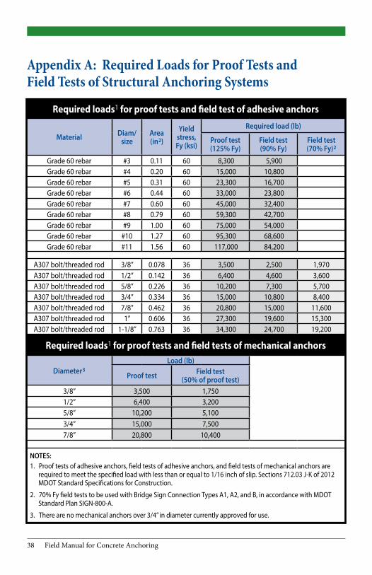
Required loads1 for proof tests and field test of adhesive anchors
Material Diam/ size
Area (in2)
Yield stress, Fy (ksi)
Required load (lb)
Proof test (125% Fy)
Field test (90% Fy)
Field test (70% Fy)2
Grade 60 rebar #3 0.11 60 8,300 5,900 Grade 60 rebar #4 0.20 60 15,000 10,800 Grade 60 rebar #5 0.31 60 23,300 16,700 Grade 60 rebar #6 0.44 60 33,000 23,800 Grade 60 rebar #7 0.60 60 45,000 32,400 Grade 60 rebar #8 0.79 60 59,300 42,700 Grade 60 rebar #9 1.00 60 75,000 54,000 Grade 60 rebar #10 1.27 60 95,300 68,600 Grade 60 rebar #11 1.56 60 117,000 84,200
A307 bolt/threaded rod 3/8” 0.078 36 3,500 2,500 1,970A307 bolt/threaded rod 1/2” 0.142 36 6,400 4,600 3,600A307 bolt/threaded rod 5/8” 0.226 36 10,200 7,300 5,700A307 bolt/threaded rod 3/4” 0.334 36 15,000 10,800 8,400A307 bolt/threaded rod 7/8” 0.462 36 20,800 15,000 11,600A307 bolt/threaded rod 1” 0.606 36 27,300 19,600 15,300A307 bolt/threaded rod 1-1/8” 0.763 36 34,300 24,700 19,200
Required loads1 for proof tests and field tests of mechanical anchors
Diameter3Load (lb)
Proof test Field test (50% of proof test)
3/8” 3,500 1,750 1/2” 6,400 3,200 5/8” 10,200 5,100 3/4” 15,000 7,500 7/8” 20,800 10,400
NOTES:1. Proof tests of adhesive anchors, field tests of adhesive anchors, and field tests of mechanical anchors are
required to meet the specified load with less than or equal to 1/16 inch of slip. Sections 712.03 J-K of 2012 MDOT Standard Specifications for Construction.
2. 70% Fy field tests to be used with Bridge Sign Connection Types A1, A2, and B, in accordance with MDOT Standard Plan SIGN-800-A.
3. There are no mechanical anchors over 3/4” in diameter currently approved for use.
Appendix A: Required Loads for Proof Tests and Field Tests of Structural Anchoring Systems

Field Manual for Concrete Anchoring 39
Appendix B: MDOT Form 1928 (Adhesive Anchoring System Proof Test)
Michigan Department Of Transportation
1928 (01/15)
ADHESIVE ANCHORING SYSTEM PROOF TEST
CONTROL SECTION JOB NUMBER REPORT NUMBER
CONTRACTOR JOB/STRUCTURE DESCRIPTION
ADHESIVE PRODUCT EMBEDMENT DEPTH DIAMETER/SIZE
INSTALLED BY TIME INSTALLED DATE INSTALLED
TESTED BY TIME TESTED DATE TESTED
TEMP. AT INSTALLATION TEMP. AT TESTING REQUIRED PROOF LOAD
HYDRAULIC PUMP/RAM NUMBER
DISPLACEMENT (in) NOTE: MAX ALLOW. = 1/16 (0.0625) GAGE
PRESSURE (psi)
LOAD (lbs) TEST NO. 1 TEST NO. 2 TEST NO. 3 TEST NO. 4
0 500
1000 1500 2000 2500 3000 3500 4000 4500 5000 5500 6000 6500 7000 7500 8000
PASS/FAIL COMMENTS
Clear Form

40 Field Manual for Concrete Anchoring
Michigan DepartmentOf Transportation
1927 (01/15)
MECHANICAL ANCHORING SYSTEM PROOF TEST
CONTROL SECTION JOB NUMBER REPORT NUMBER
CONTRACTOR JOB/STRUCTURE DESCRIPTION
ANCHOR TYPE EMBEDMENT DEPTH DIAMETER
INSTALLED BY DATE INSTALLED REQUIRED PROOF LOAD
TESTED BY DATE TESTED
HYDRAULIC PUMP/RAM NUMBER
DISPLACEMENT (in) GAGE
PRESSURE(psi)
LOAD(lbs) TEST NO. 1 TEST NO. 2 TEST NO. 3 TEST NO. 4
0
500
1000
1500
2000
2500
3000
3500
4000
4500
5000
5500
6000
6500
7000
7500
8000
PASS/FAILCOMMENTS
Clear Form
Appendix C: MDOT Form 1927 (Mechanical Anchoring System Proof Test)
Prepared by: MDOT Graphics/Bureaus/Statewide Services/Construction/C&T/Field Manual for Pile Welding/ Field Manual for Concrete Anchoring (kh 5/15)
Michigan Department Of Transportation
1928 (01/15)
ADHESIVE ANCHORING SYSTEM PROOF TEST
CONTROL SECTION JOB NUMBER REPORT NUMBER
CONTRACTOR JOB/STRUCTURE DESCRIPTION
ADHESIVE PRODUCT EMBEDMENT DEPTH DIAMETER/SIZE
INSTALLED BY TIME INSTALLED DATE INSTALLED
TESTED BY TIME TESTED DATE TESTED
TEMP. AT INSTALLATION TEMP. AT TESTING REQUIRED PROOF LOAD
HYDRAULIC PUMP/RAM NUMBER
DISPLACEMENT (in) NOTE: MAX ALLOW. = 1/16 (0.0625) GAGE
PRESSURE (psi)
LOAD (lbs) TEST NO. 1 TEST NO. 2 TEST NO. 3 TEST NO. 4
0 500
1000 1500 2000 2500 3000 3500 4000 4500 5000 5500 6000 6500 7000 7500 8000
PASS/FAIL COMMENTS
Clear Form


