Field Manual for Erosion and Sediment Control In Georgia Fourth Edition 2002 4310 Lexington Road P.O. Box 8024 Athens, GA 30603 706-542-3065 Fax 706-542-4242 www.gaswcc.org Georgia Soil and Water Conservation Commission S T A T E S O I L & W A T E R C O N S E R V A T I O N C O M M I S S I O N G E O R G I A OUR 1937 BASIC HERITAGE SOIL-
Transcript
Field Manual forErosion and Sediment Control
In Georgia
Fourth Edition2002
4310 Lexington RoadP.O. Box 8024
Athens, GA 30603706-542-3065
Fax 706-542-4242www.gaswcc.org
Georgia Soil and WaterConservation Commission
STATESOIL
&
WATER
CONSERVATIONCOM
MISSION
GEORGIA
OUR
1937
BASIC HERITAGE
SOIL-
The preparation of this Field Manual was financed inpart through a grant from the U.S. Environmental Pro-tection Agency to the Environmental Protection Divi-sion of the Georgia Department of Natural Resourcesunder Provisions of Section 319(h) of the Federal Wa-ter Pollution Control Act, as amended.
All programs and services of the federal, state and local agencieslisted above are available on a nondiscriminatory basis withoutregard to race, color, national origin, religion, sex, age, marital sta-tus, handicap or disability. If you need this document in an alterna-tive format, call (706) 542-3065
2005
ii
iii
(This page left blank intentionally.)
iv
TABLE OF CONTENTS
Introduction vi
Vegetative Best Management Practices
Bf Buffer Zone 2
Cs Coastal Dune Stabilization 6
Ds1 Disturbed Area Stabilization 10(With Mulching Only)
Ds2 Disturbed Area Stabilization 12(With Temporary Seeding)
Ds3 Disturbed Area Stabilization 18(With Permanent Vegetation)
Wt Vegetated Waterway or 120Stormwater Conveyance Channel
The Erosion and Sediment Control Act 124of 1975, as amended
National Pollution Discharge 131Elimination System (NPDES) Permit
Construction Checklist 132
Glossary 146
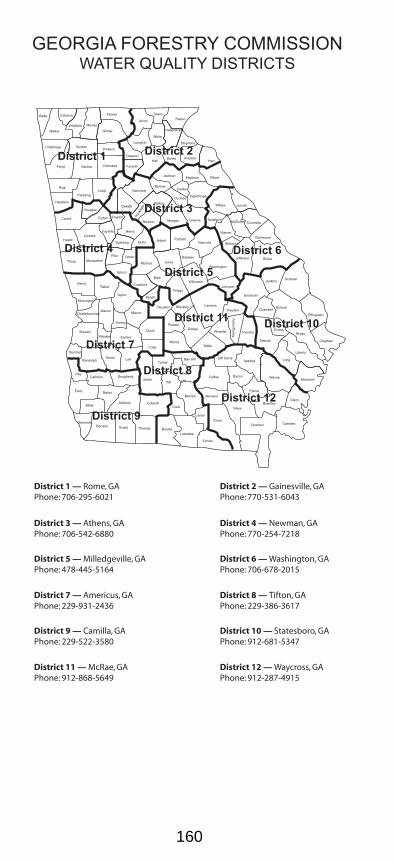
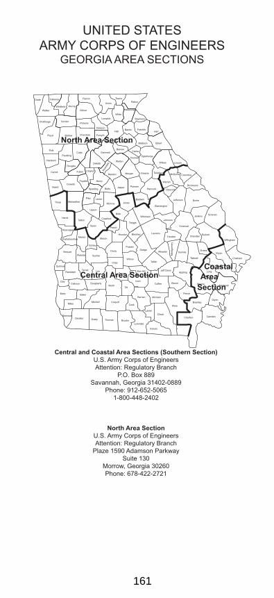
Points of Contact 155
Page
vi
The First Edition of this Field Manual wasprinted in 1979 and revised in 1988, 1997 and2002. Georgia’s Erosion and SedimentationLaw has been amended several times sincewith major changes to the Law occurring in1994, 1995 and 2000. The emphasis shiftedfrom water quality to meeting “minimum re-quirements.” This means that Best Manage-ment Practices (BMPs) must be properly de-signed, installed and maintained in accor-dance with sound conservation and engineer-ing principals.
This Field Manual has been prepared prima-rily to assist field personnel involved in on-siteland-disturbing activities. It should be helpfulas a quick reference in the actual installationand maintenance of BMPs. (The inclusion ofdetailed design information has purposelybeen kept to a minimum.) For more detailedinformation, The Manual for Erosion and Sedi-ment Control in Georgia should be consulted.
BMPs are vegetative measures and structuralpractices that control the erosion of soil andthe resulting sedimentation. The law mandatesthat all BMPs stand up to a 25-year rainfallevent or the land-disturber is subject to se-vere civil penalties.
Good erosion control and sediment reductiondoes not require a rocket scientist or a “legaleagle.” The key to well-planned land-disturb-ing activities is well-informed managers in thefield; the individuals for whom this manual iswritten. Common sense and a working knowl-edge of the tools nature has provided will leadto good site development.
INTRODUCTION
vii
Georgia’s Law is called the “Erosion and Sedi-mentation Act.” Erosion and sedimentation aretwo separate processes. If erosion is con-trolled, sediment is not produced. Therefore,to practice good erosion and sediment con-trol (E&SC), emphasis has to be placed oncontrolling erosion at the source. Sedimentcontrol should be considered the last line ofdefense. Allowing any erosion to occur is thefirst step towards noncompliance.
Complete erosion control usually does not in-volve engineered structures, just sensibleplanning and the immediate application ofground covers including mulch and vegetation.Nature has provided us with an abundance oftrees, shrubs and grasses, all of which are ef-fective erosion control tools. USE THEM! Anduse them wisely in a timely manner.
If your E&SC plan does not show a vegetativebuffer around a site but there is an area onthe perimeter that does not require clearing,then save the existing vegetation! A good veg-etative buffer 25'-35' can trap 85-95% of thesediment in runoff water.
If a site is properly engineered, cut and fillslopes can be mulched or vegetated daily.Mulch does not require water or fertilizer orlime. A good application of mulch can reducesoil loss by up to 98%. When in doubt, mulch!
Use conventional planting methods, when fea-sible. Sodding may initially be moreexpensive...but how much more? If a site hasto be re-planted several times, then it just maybe cheaper to sod rather than seed bareslopes. Even if the sod should die, most sod-ded areas will protect bare areas from ero-sion during the duration of the land-disturbingactivity.
viii
To summarize, save as much existing vegeta-tion as possible and mulch/vegetate as earlyand as frequently as possible. Also, as a lastline of defense, install traps for sediment assoon as possible. This will lead to good ero-sion and sediment control on any site.
The BMPs listed in this manual are intendedto provide minimum control for erosion andsedimentation problems as required by StateLaw. However, other measures and innova-tive practices that are at least as effective asthe listed practices are encouraged. Also, whilethe emphasis is on meeting the requirementsof the State Law, land disturbers must alsocomply with all other local, state and federallaws including that of the Army Corps of Engi-neers (COE) on Section 404. Local IssuingAuthorities must ensure compliance on allregulations before issuing a land disturbingactivity (LDA) permit.
The Commission is grateful to the several re-viewers who assisted in the preparation of thispublication. We welcome notice of any errorsor omissions we may correct in our next pub-lication.
Throughout the Manual, many provisions ofthe E&SC Law and resulting rules and regu-lations have been paraphrased or shortenedfor convenience. Any interpretations or opin-ions expressed in this shortened format arethose of the Commission and are provided forquick reference only. In matters of litigation,the Law and the Courts are the final word.
1
VEGETATIVEBEST MANAGEMENT
PRACTICES
Bf Buffer Zone 2
Cs Coastal Dune Stabilization 6
Ds1 Disturbed Area Stabilization 10(With Mulching Only)
Ds2 Disturbed Area Stabilization 12(With Temporary Seeding)
Ds3 Disturbed Area Stabilization 18(With Permanent Vegetation)
DEFINITIONPlanting vegetation on bare dunes or wheredunes are to be established.
PURPOSE• Prevent dune erosion from wind or waves
by planting vegetation.• Provide for the development or enhance-
ment of dunes.
INSTALLATION• Install in accordance with an approved de-
sign/study.• Install in accordance with all federal, state
and local regulations.• Protect dunes from vehicular and human
traffic.• Irrigate during the first year to obtain good
survival.• Mulch areas to be planted.• Native plants commercially available that
may be planted are included in Table 1.
7
Cs
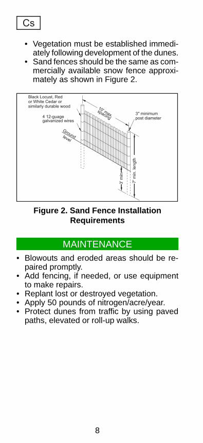
Sand Fences• Install according to plans, if shown.• Use posts made of Black Locust, Red or
White Cedar, or similarly durable wood.• Use posts with minimum length of 7 feet
and minimum diameter of 3 inches.• Space posts at a maximum of 10 feet.• Entrench posts a minimum of 3 feet.• Attach fence to posts with four 12-gauge
galvanized wires.
Table 1.Planting Requirements for Native Plants
Species Stock Date Depth
Marshhay Cordgrass Plants Spring 4"-5"(Spartina patens)
Bitter Panicum Rhizomes Spring Abt 4"(Panicum amarum)
Coastal Panigrass Seeds or Spring 1"-3"(Panicum amarum v. plantsamaralum)
Figure 1. Sand Fence and Native Plants
8
• Vegetation must be established immedi-ately following development of the dunes.
• Sand fences should be the same as com-mercially available snow fence approxi-mately as shown in Figure 2.
Cs
MAINTENANCE• Blowouts and eroded areas should be re-
paired promptly.• Add fencing, if needed, or use equipment
to make repairs.• Replant lost or destroyed vegetation.• Apply 50 pounds of nitrogen/acre/year.• Protect dunes from traffic by using paved
paths, elevated or roll-up walks.
Figure 2. Sand Fence InstallationRequirements
Black Locust, Redor White Cedar orsimilarly durable wood
4 12-guagegalvanized wires
Groundlevel
10' max,spacing
3" minimumpost diameter
3' m
in.
7' m
in.
len
gth
9
(This page left blank intentionally.)
10
Ds1 DISTURBED AREASTABILIZATION
(WITH MULCHING ONLY)
DEFINITIONA temporary cover of plant residues appliedto the soil surface for a period of six (6) monthsor less when seeding is not practical.
PURPOSE• Reduce runoff, erosion, and sedimentation.• Reduce dust.• Conserve moisture.• Prevent surface compaction and crusting.• Control undesirable vegetation.
INSTALLATION• Install all other required BMPs first.• Grade site, if possible, to permit the use of
equipment for applying and anchoringmulch.
• Loosen compacted soil, if possible, to adepth of three (3) inches.
• Apply straw or hay uniformly, as shown inTable 1, by hand or mechanical equipment,and anchor by pressing into soil or usingnetting.
11
• Mulch on slopes greater than 3% should beanchored with emulsified asphalt (GradeAE-5 or SS-1) or other suitable tackifier.
• Wood waste on slopes flatter than 3:1 donot need anchoring.
• Mulch shall be applied to all disturbed ar-eas left inactive for fourteen days.
Ds1
MAINTENANCE
REFERENCES
• Add mulch as needed to maintain the sug-gested depth.
• If organic mulch is to be left and incorpo-rated into the soil, apply 20-30 pounds ofNitrogen in addition to the fertilizer requiredfor vegetation.
• Mb Erosion Control Matting and Blankets
Table 1. Mulching ApplicationRequirements
Material Rate Depth
Straw or hay - 2" to 4"
Wood waste,chips, sawdust,
bark - 2" to 3"
Cutback 1200 gal./acre, ---asphalt 1/4 gal./sq. yd. or
See manufacturer’srecommendations
Polyethylene Secure with soil, ---film anchors, weights
Geotextiles, See manufacturer’s ---jute matting, recommendationsnetting, etc.
12
Ds2 DISTURBED AREASTABILIZATION
(WITH TEMPORARY SEEDING)
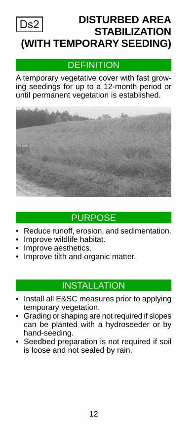
DEFINITIONA temporary vegetative cover with fast grow-ing seedings for up to a 12-month period oruntil permanent vegetation is established.
PURPOSE• Reduce runoff, erosion, and sedimentation.• Improve wildlife habitat.• Improve aesthetics.• Improve tilth and organic matter.
INSTALLATION• Install all E&SC measures prior to applying
temporary vegetation.• Grading or shaping are not required if slopes
can be planted with a hydroseeder or byhand-seeding.
• Seedbed preparation is not required if soilis loose and not sealed by rain.
13
• When the soil is sealed or crusted, it shouldbe pitted, trenched or scarified to provide aplace for seed to lodge and germinate.
• Agricultural lime is not required.• Fertilize low fertility soils prior to or during
planting at the rate of 500-700 pounds peracre of 10-10-10 fertilizer or equivalent (12-16 pounds/1000 square feet).
• It is imperative that you check the tag onthe bag of seed to verify the type and ger-mination of the seed to be planted.
Ds2
• Apply seed by hand, cyclone seeder, drillor hydro-seeder. Seed planted with a drillshould be planted 1/4"-1/2" deep. Refer toPure Live Seed (PLS) in the Glossary.
• Apply in accordance with specifications onthe E&SC plan. If information is not avail-able, select a temporary cover from Table1.
• Temporary cover shall be applied to all dis-turbed areas left idle for fourteen days. (Ifan area is left idle for 6 months, permanentcover shall be applied.)
Figure 1. Typical Tag on Bag of Seed
14
Ds2
MAINTENANCE
• Re-seed areas where an adequate standof temporary vegetation fails to emerge orwhere a poor stand exists.
REFERENCES• Mb Erosion Control Matting and Blankets
• Ds1 Disturbed Area Stabilization(With mulching only)
• Pm Polyacrylamide (PAM)
15
Species Rates Per Rates per1,000 sq. ft. Acre M - L P C
Planting Dates by Region
Table 1. Some Temporary Plant Species, Seeding Rates and Planting DatesD
s2
1. Unusual site conditions may require heavier seeding rates.2. Seeding dates may need to be altered to fit temperature variations and local conditions.3. For Major Land Resource Areas (MLRAs), see page 50.4. Seeding rates are based on pure live seed (PLS).
Millet, Pearl 1.1 lbs. 50 lbs. 5/15-7/15 5/1-7/31 4/15-8/15
16
Table 1. Some Temporary Plant Species, Seeding Rates and Planting Dates (continued) Ds2
1. Unusual site conditions may require heavier seeding rates.2. Seeding dates may need to be altered to fit temperature variations and local conditions.3. For Major Land Resource Areas (MLRAs), see page 50.4. Seeding rates are based on pure live seed (PLS).
Species Rates Per Rates per1,000 sq. ft. Acre M - L P C
Planting Dates by Region
17
Ds2
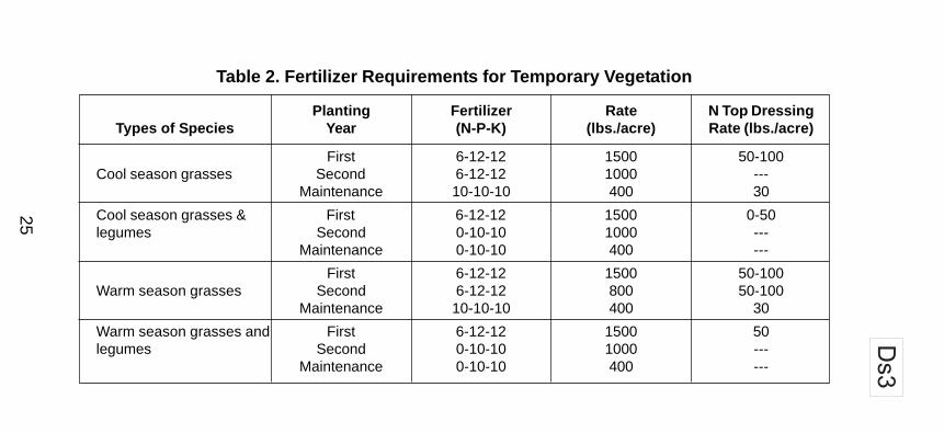
Table 2. Fertilizer Requirements for Temporary Vegetation
Planting Fertilizer Rate N Top DressingTypes of Species Year (N-P-K) (lbs./acre) Rate (lbs./acre)
First 6-12-12 1500 50-100Cool season grasses Second 6-12-12 1000 ---
Maintenance 10-10-10 400 30
Cool season grasses & First 6-12-12 1500 0-50legumes Second 0-10-10 1000 ---
Maintenance 0-10-10 400 ---
Temporary cover cropsFirst 10-10-10 500 30
seeded alone
First 6-12-12 1500 50-100Warm season grasses Second 6-12-12 800 50-100
Maintenance 10-10-10 400 30
18
Ds3 DISTURBED AREASTABILIZATION
(WITH PERMANENT SEEDING)
DEFINITION
A permanent vegetative cover using grasses,trees, shrubs or legumes on highly erodibleor critically eroded lands.
PURPOSE
• Reduce runoff and erosion.• Improve wildlife habitat.• Improve aesthetics.• Improve tilth and organic matter.• Reduce downstream complaints.• Reduce likelihood of legal action.• Reduce likelihood of work stoppage due to
legal action.• Increase “good neighbor” benefits.
INSTALLATION
• Use conventional planting methods, if pos-sible.
• Apply according to approved plan, if shown,or refer to Table 1.
19
• Check the tag on the bag of seed to verifythe type and germination of the seed to beplanted and the date of the test.
Ds3
• Scarify, pit or trench sealed or crusted soil.• Fertilize based on soil tests or as shown in
Table 2.• Apply agricultural lime as prescribed by soil
tests or at a rate of 1 to 2 tons per acre.• Apply seed by hand, cyclone seeder, drill
or hydro-seeder. Seed planted with a drillshould be planted 1/4"-1/2" deep.
• Straw or hay mulch shall be applied at arate of 2 or 2.5 tons per acre.
• Irrigation should be used to supplementrainfall, but not to the extent to cause ero-sion.
Figure 1. Typical Tag on a Bag of Seed
20
Ds3
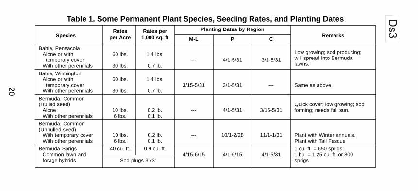
Table 1. Some Permanent Plant Species, Seeding Rates, and Planting DatesRates Rates per
Species per Acre 1,000 sq. ft RemarksPlanting Dates by Region
M-L P C
Bahia, PensacolaAlone or with 60 lbs. 1.4 lbs. Low growing; sod producing;
temporary cover --- 4/1-5/31 3/1-5/31 will spread into Bermuda
With other perennials 30 lbs. 0.7 lb. lawns.
Bahia, WilmingtonAlone or with 60 lbs. 1.4 lbs. temporary cover 3/15-5/31 3/1-5/31 --- Same as above.With other perennials 30 lbs. 0.7 lb.
Drought tolerant. Full sun orOnly Only partial shade.
Crown Vetch Mix with 30 lbs. Tall Fescue orWith winter annuals 15 lbs. 0.3 lb. 9/1-10/15 9/1-10/15 --- 15 lbs. Rye; inoculate seed;or cool season grasses plant only North of Atlanta.
Fescue, Tall Can be mixed with perennialAlone 50 lbs. 1.1 lbs. 3/1-4/15 9/1-10/15 --- Lespedezas or Crown Vetch;With other perennials 30 lbs. 0.7 lb. or not for droughty soils or heavy
8/15-10/15 use areas.
Lespedeza, Sericea Widely adapted and lowmaintenance; takes 2-3 years toestablish; inoculate seed with
Scarified 60 lbs. 1.4 lbs. 4/1-5/31 3/15-5/31 3/1-5/15 EL inoculant.; mix withWeeping Lovegrass, CommonBermuda, Bahia or Tall Fescue.
22
Ds3
Table 1. Some Permanent Plant Species, Seeding Rates, and Planting Dates (continued)Rates Rates per
RemarksSpecies per Acre 1,000 sq. ftPlanting Dates by Region
M-L P CLespedeza, Sericea(cont.) Mix with Tall Fescue or winter
Cut when seed is mature but3 tons 138 lbs. 10/1-2/28 10/1-1/31 10/15-1/15 before it shatters. Add Tall
Seed-bearing hay Fescue or winter annuals.
Lespedeza, AmbroVirgata or Appalow
Spreading growth with heightScarified 60 lbs. 1.4 lbs. 4/1-5/31 3/15-5/31 3/1-5/15 of 18"-24"; good in urban
areas; slow to develop goodstands; mix with Weeping
Unscarified 75 lbs. 1.7 lbs. 9/1-2/28 9/1-2/28 9/1-2/28 Lovegrass, Common Bermuda,Bahia Tall Fescue or winterannuals; do not mix withSericea Lespedeza; inoculateseed with EL inoculant.
23
Ds3
Table 1. Some Permanent Plant Species, Seeding Rates, and Planting Dates (continued)Rates Rates per
Species per Acre 1,000 sq. ft RemarksPlanting Dates by Region
M-L P C
Lespedeza, Shrub(Lespedeza Bicolor or 3'x3' spacing 10/1-3/31 11/1-3/15 11/15-2/28 Plant in small clumps forLespedeza Thumbergii) wildlife food and cover.
Plants
Lovegrass, weeping Quick cover; drought tolerant;Alone 4 lbs. 0.1 lbs. 4/1-5/31 3/15-5/31 3/1-5/31 grows well with SericeaWith other perennials 2 lbs. 0.05 lbs. Lespedeza on road-banks and
other steep slopes; short lived.
For very wet sites such asMaidencane sprigs 2'x3' spacing 2/1-3/31 2/1-3/31 2/1-3/31 riverbanks and shorelines. Dig
sprigs locally.
Grows well on coastal sandPanicgrass, Atlantic 20 lbs. 0.5 lbs. --- 3/1-4/30 3/1-4/30 dunes; mix with SericeaCoastal Lespedeza but not on sand
dunes.
24
Ds3
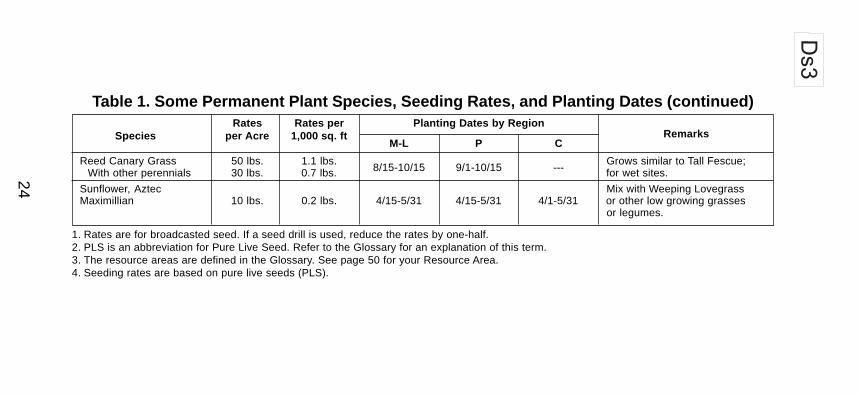
Table 1. Some Permanent Plant Species, Seeding Rates, and Planting Dates (continued)Rates Rates per
RemarksSpecies per Acre 1,000 sq. ftPlanting Dates by Region
Grows similar to Tall Fescue;With other perennials 30 lbs. 0.7 lbs. for wet sites.
Sunflower, Aztec Mix with Weeping LovegrassMaximillian 10 lbs. 0.2 lbs. 4/15-5/31 4/15-5/31 4/1-5/31 or other low growing grasses
or legumes.
1. Rates are for broadcasted seed. If a seed drill is used, reduce the rates by one-half.2. PLS is an abbreviation for Pure Live Seed. Refer to the Glossary for an explanation of this term.3. The resource areas are defined in the Glossary. See page 50 for your Resource Area.4. Seeding rates are based on pure live seeds (PLS).
25
Ds3
Table 2. Fertilizer Requirements for Temporary Vegetation
Planting Fertilizer Rate N Top DressingTypes of Species Year (N-P-K) (lbs./acre) Rate (lbs./acre)
First 6-12-12 1500 50-100Cool season grasses Second 6-12-12 1000 ---
Maintenance 10-10-10 400 30
Cool season grasses & First 6-12-12 1500 0-50legumes Second 0-10-10 1000 ---
Maintenance 0-10-10 400 ---
First 6-12-12 1500 50-100Warm season grasses Second 6-12-12 800 50-100
Maintenance 10-10-10 400 30
Warm season grasses and First 6-12-12 1500 50legumes Second 0-10-10 1000 ---
Maintenance 0-10-10 400 ---
26
Ds3
Figure 3. Sericea Lespedeza
Figure 2. Crown Vetch
27
Ds3
MAINTENANCE• Re-seed areas where an adequate stand
of vegetation fails to emerge or where a poorstand exists.
• Apply fertilizer per Table 2.• Apply one ton of agricultural lime or as indi-
cated by soil test every 4-6 years.• Mow Bermuda and Bahia as desired. Mow
Sericea Lespedeza only after frost to en-sure seeds are mature.
• Maintain 6" or more of top growth.
REFERENCES
• Mb Erosion Control Matting and Blankets
• Ds1 Disturbed Area Stabilization(With mulching only)
• Ds2 Disturbed Area Stabilization(With temporary seeding)
28
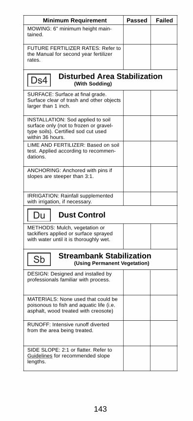
Ds4 DISTURBED AREASTABILIZATION
(WITH SODDING)
DEFINITION
A permanent vegetation using sods on highlyerodible or critically eroded lands.
PURPOSE
• Establish immediate ground cover.• Reduce runoff and erosion.• Improve aesthetics and land value.• Reduce dust and sediments.• Stabilize waterways and critical areas.• Filter sediments, nutrients and bugs.• Reduce downstream complaints.• Reduce likelihood of legal action.• Reduce likelihood of work stoppage due to
legal action.• Increase “good neighbor” benefits.
INSTALLATION• Bring soil surface to final grade. Clear sur-
face of trash, woody debris, stones andclods larger than 1". Apply sod to soil sur-faces only and not frozen surfaces, or graveltype soils
29
• Agricultural lime should be applied basedon soil tests or at a rate of 1 to 2 tons peracre.
• Lay sod with tight joints and in straight lines.Don’t overlap joints. Stagger joints and donot stretch sod.
• On slopes steeper than 3:1, sod should beanchored with wooden or biodegradablepins or other approved methods.
• Installed sod should be rolled or tamped toprovide good contact between sod and soil.
• Irrigate sod and soil to a depth of 4" imme-diately after installation.
• Sod should not be cut or spread in extremelywet or dry weather.
• Irrigation should be used to supplementrainfall for a minimum of 2-3 weeks.
Ds4
Table 1. Fertilizer Requirements for SoilSurface Application
Fertilizer Fertilizer FertilizerType Rate Rate Season
(lbs./acre) (lbs./sq. ft.)
10-10-10 1000 .025 Fall
• Topsoil properly applied will help guaran-tee a stand. Don’t use topsoil recentlytreated with herbicides or soil sterilants.
• Mix fertilizer into soil surface. Fertilize basedon soil tests or Table 1. For fall planting ofwarm season species, half the fertilizershould be applied at planting and the otherhalf in the spring.
MATERIALS
• Sod selected should be certified. Sod grownin the general area of the project is desir-able.
30
Ds4
• Sod should be machine cut and contain3/4" ±1/4" of soil, not including shoots orthatch.
• Sod should be cut to the desired size within±5%. Torn or uneven pads should be re-jected.
• Sod should be cut and installed within 36hours of digging.
• Avoid planting when subject to frost heaveor hot weather if irrigation is not available.
• The sod type should be shown on the plansor installed according to Table 2. See page50 for your Resource Area.
MAINTENANCE• Re-sod areas where an adequate stand of
sod is not obtained.
Table 2. Sod Planting Requirements
Common M-L, P,CBermudagrass Tifway P,C Warm
Tifgreen P,C weatherTiflawn P,C
Bahiagrass Pensacola P,C Warmweather
Centipede --- P,C Warmweather
CommonSt. Augustine Bitterblue C Warm
Raleigh weather
Zoysia Emerald P,C WarmMyer weather
Tall Fescue Kentucky 31 M-L, P Coolweather
Resource GrowingGrass Varieties Area Season
31
Ds4
REFERENCES• Mb Erosion Control Matting and Blankets
• Ds1 Disturbed Area Stabilization(With mulching only)
• Ds2 Disturbed Area Stabilization(With temporary seeding)
• Ds3 Disturbed Area Stabilization(With permanent seeding)
Types of Planting Fertilizer Rate Nitrogen TopSpecies Year (N-P-K) (lbs./acre) Dressing Rate
(lbs./acre)
Table 3. Fertilizer Requirements for Sod
Cool First 6-12-12 1500 50-100season Second 6-12-12 1000 ---grasses Maintenance 10-10-10 400 30
Warm First 6-12-12 1500 50-100season Second 6-12-12 800 50-100grasses Maintenance 10-10-10 400 30
• New sod should be mowed sparingly. Grassheight should not be cut less than 2"-3" oras specified.
• Apply one ton of agricultural lime as indi-cated by soil test or every 4-6 years.
• Fertilize grasses in accordance with soiltests or Table 3.
32
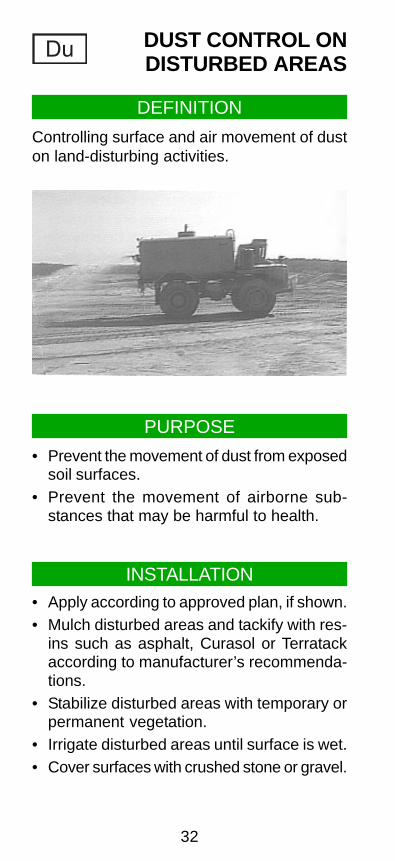
Du DUST CONTROL ONDISTURBED AREAS
DEFINITION
Controlling surface and air movement of duston land-disturbing activities.
PURPOSE
• Prevent the movement of dust from exposedsoil surfaces.
• Prevent the movement of airborne sub-stances that may be harmful to health.
INSTALLATION• Apply according to approved plan, if shown.• Mulch disturbed areas and tackify with res-
ins such as asphalt, Curasol or Terratackaccording to manufacturer’s recommenda-tions.
• Stabilize disturbed areas with temporary orpermanent vegetation.
• Irrigate disturbed areas until surface is wet.• Cover surfaces with crushed stone or gravel.
33
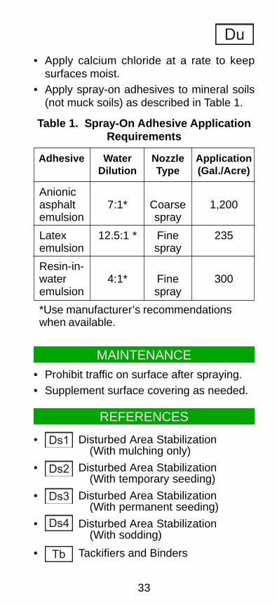
• Apply calcium chloride at a rate to keepsurfaces moist.
• Apply spray-on adhesives to mineral soils(not muck soils) as described in Table 1.
A protective covering (blanket) or soil stabili-zation mat used to establish permanent veg-etation on steep slopes, channels, or shore-lines.
PURPOSE• Reinforce turf.• Reduce erosion.• Reinforce channels.• Provide protective covering.
INSTALLATION• Install on slopes steeper than 2.5:1 and
greater than 10 feet in height and in areasof concentrated flow.
• Install according to approved plan, if shown.• All mats and netting should be appropriately
staked to prevent shifting.• These materials must be installed accord-
ing to the manufacturer’s specifications.
35
Jute or Excelsior (Wood Fiber) Matting• Seed area.• Cover an area completely with a heavy,
uniform, jute yarn or organic mulch.• Apply on areas with steep slopes, water-
courses or where vegetation needs to bequickly established.
Mb
Fiberglass Roving• Seed area.• Apply fiberglass with a compressed air
ejector, at a rate of 1/2-1 ton per acre andtack with emulsifier (asphalt) at a rate of25-35 gal/1000 ft2 or as recommended bythe manufacturer.
• Place in watercourses or on moderateslopes for stabilization and to provide asuitable microclimate for seeds.
Bonded Fiber Matrix• A hydraulically applied bonded fiber ma-
trix which upon drying shall adhere to thesoil in the form of a continuous 100 percent coverage biodegradable blanket.
• The bonded matrix shall not be appliedon saturated soils.
• See manufacturer’s specifications for in-stallation instructions.
Figure 1. Installation of Jute Matting
36
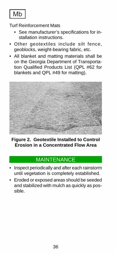
Turf Reinforcement Mats• See manufacturer’s specifications for in-
stallation instructions.• Other geotextiles include silt fence,
geoblocks, weight-bearing fabric, etc.• All blanket and matting materials shall be
on the Georgia Department of Transporta-tion Qualified Products List (QPL #62 forblankets and QPL #49 for matting).
Mb
MAINTENANCE• Inspect periodically and after each rainstorm
until vegetation is completely established.• Eroded or exposed areas should be seeded
and stabilized with mulch as quickly as pos-sible.
Figure 2. Geotextile Installed to ControlErosion in a Concentrated Flow Area
(This page left blank intentionally.)
37
38
Pm POLYACRYLAMIDE(PAM)
DEFINITION
The land application of a product containinganionic polyacrylamide (PAM) acting as a tem-porary soil binding agent to reduce soil ero-sion.
PURPOSE
PAM is used to reduce erosion from wind andwater on construction sites and agriculturallands. Other benefits may include improvedwater quality, infiltration, soil fertility, and vis-ibility.
INSTALLATION
• Apply according to approved plan, if shown.• These materials should be applied accord-
ing to the manufacturer’s specifications.These products are site specific.
• Use setbacks when applying anionic PAMnear natural waterbodies.
• Never add water to PAM, add PAM slowlyto water. If water is added to PAM, “globs”may form which can clog dispensers.
• NOT ALL POLYMERS ARE PAM.• Only anionic PAM shall be used. Cationic
PAM is toxic and shall not be used.
MAINTENANCE
Maintenance will consist of reapplying PAMto disturbed areas including high use trafficareas, which interfere in the performance ofthis practice.
(This page left blank intentionally.)
39
40
Sb STREAMBANKSTABILIZATION
(USING PERMANENT VEGETATION)
DEFINITION
The use of readily available native plant ma-terials to maintain and enhance streambanks,or to prevent, or restore and repair smallstreambank erosion problems.
PURPOSE• Lessen the impact of rain directly on the soil.• Trap sediment from adjacent land.• Form a root mat to stabilize and reinforce
the soil on the streambank.• Provide wildlife habitat.• Enhance the appearance of the stream.• Lower summertime water temperatures for
a healthy aquatic population.
NOTE: Careful thought, planning and execu-tion is required to assure that the streambankstabilization project is done efficiently andcorrectly. Please refer to SSWCC’s Guidelinesfor Streambank Restoration for more detailedinformation.
41
Sb
SELECTED MEASURES
• Revegetation includes seeding and soddingof grasses, seeding in combination with ero-sion control fabrics, and the planting ofwoody vegetation (shrubs and trees).
• Use jute mesh and other geotextiles to aidin soil stabilization and revegetation.
Live Stake• Fresh, alive woody plant cuttings tamped
into the ground as stakes, intended to rootand grow into mature shrubs that will sta-bilize soils and restore the riparian zonehabitats.
• Willow species work best.• Provides no immediate streambank sta-
bilization.
Joint Planting• Installation of live willow stakes between
rock previously placed along thestreambank.
• Rock needs to be loosely dumped or handplaced and no thicker than 2 feet.
• Enables a bank previously installed withconventional rip-rap to become natural-ized.
Figure 1. Illustration of a Live Stake
Note:
Rooted/leafed condition of the
living plant material is not
representative at the time of
installation.
Robbin B. Sotir & Associates
LIVE CUTTINGS
42
Live Fascine• Sausage-like bundles of live cut branches
placed into trenches along thestreambank.
• Willow species work best.• Provides immediate protection from ero-
sion when properly used and installed.• Creates very little site disturbance as
com-pared to other systems.• Works especially well when combined
with surface covers such as jute mesh orcoir fabrics.
Sb
Figure 2. Illustration of Joint Planting
Note:
Rooted/leafed condition of the living
plant material is not representative at
the time of installation.
Robbin B. Sotir & Associates
LIVE STAKE RIPRAP
Figure 3. Illustration of a Live Fascine
LIVE BRANCHES
DEAD STOUT STAKE
LIVE STAKE
TWINE
LIVE BRANCHES
Note:
Rooted/leafed condition of the living
plant material is not representative
at the time of installation.
Robbin B. Sotir & Associates
43
Sb
Brushmattress• Combination of living units that form an
• Living units used include live stakes, livefascines, and a mattress branch cover(long, flexible branches placed against thebank surface).
• Requires a great deal of live material.• Complicated and expensive to evaluate,
design, and install.• Captures sediment during flood condi-
tions.• Produces habitat rapidly, and quickly de-
velops a healthy riparian zone.
Live Cribwall• A rectangular framework of logs or tim-
bers, rock, and woody cuttings.• Requires a great deal of assessment and
understanding of stream behavior.• Can be complicated and expensive if a
supply of wood and some volunteer helpis not available.
• Develops a natural streambank or uplandslope appearance after it has begun togrow.
Figure 4. Illustration of a Brushmattress
LIVE BRANCHES
Robbin B. Sotir & Associates
STAKE
WIRE
LIVE STAKE
LIVE BRANCHES
DEAD STOUT STAKE
LIVE FASCINE
Note:
Rooted/leafed condition of the living
plant material is not representative at
the time of installation.
44
Sb
• Provides excellent habitat for a variety offish, birds, and animals.
• Very useful where space is limited onsmall, narrow stream corridors.
Branchpacking• Process of alternating layers of live
branches and soil, incorporated into ahole, gully, or slumped-out area in a slopeor streambank.
• Moderate to complex level of difficulty forconstruction.
• Produces an immediate filter barrier, re-ducing scouring conditions, repairing gullyerosion, and providing habitat cover andbank reinforcement.
• One of the most effective and inexpen-sive methods for repairing holes inearthen embankments along smallstream sites.
Figure 5. Illustration of a Live Cribwall
TIMBER/LOGS
SELECT FILL MATERIALS
EXISTING
LIVE BRANCHES
50/50 SELECT FILLROCK MIXROCK
Robbin B. Sotir & Associates
Figure 6. Illustration of Branchpacking
COMPACTED FILL
WOODEN STAKES
SELECTED ROOTED
PLANTS OR CUTTINGS
Note:
Rooted/leafed condition of the living
plant material is not representative
at the time of installation.
Robbin B. Sotir & Associates
45
Sb
MAINTENANCE• Check banks after every high-water event,
fixing gaps in the vegetative cover at oncewith structural materials or new plants, andmulching if necessary.
• Fresh cuttings from other plants may beused for repairs.
• When fertilizer is applied on the surface, itis best to apply about one-half at planting,one-fourth when new growth is about twoinches tall, and one-fourth about six weekslater.
Table 1. Streambank Erosion ProtectionMeasures Relative Costs and Complexity
Measure Relative RelativeCost Complexity
Live stake Low Simple
Joint planting Low* Simple*
Live fascine Moderate Moderate
Brushmattress Moderate Moderate toComplex
Live cribwall High Complex
Branchpacking Moderate Moderate toComplex
Conventional Low to Simple tovegetation Moderate Moderate
Conventional Moderate Moderatebank armoring to to(riprap) High Complex
*Assumes rock is in place.
46
Sb
REFERENCES
• Mb Erosion Control Matting and Blankets
• Ds1 Disturbed Area Stabilization(With mulching only)
• Ds2 Disturbed Area Stabilization(With temporary seeding)
• Ds3 Disturbed Area Stabilization(With permanent seeding)
• Ds4 Disturbed Area Stabilization(With sodding)
• Guidelines for Streambank Restoration,Georgia Soil and Water Conservation Com-mission
47
(This page left blank intentionally.)
48
Tb TACKIFIERS ANDBINDERS
DEFINITION
Substances used to anchor straw or hay mulchby causing the organic material to bind to-gether.
PURPOSE
The purpose of tackifiers and binders is toprevent the movement of mulching materialfrom the desired location. It also increases theperformance of the mulching material, so thatit can:• Increase infiltration.• Reduce wind and water erosion.• Conserve moisture and prevent surface
compaction or crusting.• Control undesirable vegetation.• Modify soil temperature.• Increase biological activity in the soil.
SPECIFICATIONS
All organic mulching materials shall be an-chored by tackifiers/binders or matting/netting.Tackifiers and binders are used to anchorwood cellulose, wood pulp fiber, and othermulch materials applied with hydroseedingequipment.
49
(This page left blank intentionally.)
50
Decatur
Miller
Baker
Mitchell
Thomas Brooks
Lowndes
Lanier
Berrien
Irwin
Ben Hill
Wilcox
Pulaski
Wilkinson
Baldwin
LincolnWilkes
TeliaferroGreene
Clarke
Oconee
Morgan
PutnamJasper
Newton
Henry
Clayton
Hancock
Walton
Warren
Glascock
Jefferson
Washington
Columbia
Richmond
Oglethorpe
Elbert
Barrow
Gwinnett
Jackson
Dekalb
Forsyth
Dawson
Gilmer
Cobb
Douglas
Polk
Haralson
Floyd Cherokee
Pickens
Union
Bartow
Gordon
Paulding
Walker
Chattooga
MurrayWhitfield
Dade
Fulton
Madison
FranklinHall
Lumpkin
White
Rabun
Habersham
TownsFanninCatoosa
Stephens
HartBanks
LaurensBleckleyHouston
Peach
Twiggs
Turner
Crisp
Dooly
Roc
kdal
e
MaconMarion
Chattahoochee
Bibb
Monroe Jones
TalbotHarris
Muscogee
Meriwether
Coweta
Fayette
Heard
Troup
Spalding
Carroll
Upson
Pike Lanier
Crawford
Taylor
Butts
CookColquitt
WorthTift
Coffee Bacon
ApplingJeff Davis
Telfair
DodgeWheeler Toombs
Tattnall
Evans
ChandlerBulloch
Effingham
ScrevenJenkins
Emanuel
Johnson
Treutlen
Montg
om
ery
Burke
McDuffie
Atkinson
Echols
Clinch
Ware
Charlton
Brantley
Pierce
Wayne
Liberty
Bryan
Long
Chatham
McIntosh
Camden
Glynn
Early
Clay
Randolph
Quitman
Terrell Lee
SumterWebster
Schley
Calhoun Dougherty
Stewart
Seminole
Grady
MAJOR LAND RESOURCE AREAS
(MLRAS) OF GRORGIA
Mountain, Blue Ridge, and
Ridges and Valley
Southern Piedomont
Southern Costal Plain, Sand Hills,
Black Lands, and Atlantic Costal
Flatwoods
51
STRUCTURALBEST MANAGEMENT
PRACTICESCd Check Dam 52
Ch Channel Stabilization 54
Co Construction Exit 56
Cr Construction Road stabilization 58
Dc Stream Diversion Channel 60
Di Diversion 64
Dn1 Temporary Downdrain Structure 66
Dn2 Permanent Downdrain Structure 70
Fr Filter Ring 72
Ga Gabion 74
Gr Grade Stabilization Structure 76
Lv Level Spreader 78
Rd Rock Filter Dam 80
Re Retaining Wall 82
Rt Retrofit 84
Sd1 Sediment Barrier 88
Sd2 Inlet Sediment Trap 94
Sd3 Temporary Sediment Basin 100
Sr Temporary Stream Crossing 106
St Storm Drain Outlet Protection 110
Su Surface Roughening 114
Tp Topsoiling 118
Wt Vegetated Waterway or 120Stormwater Conveyance Channel
52
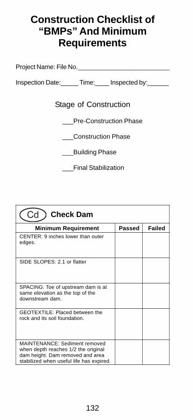
Cd CHECK DAM
DEFINITION
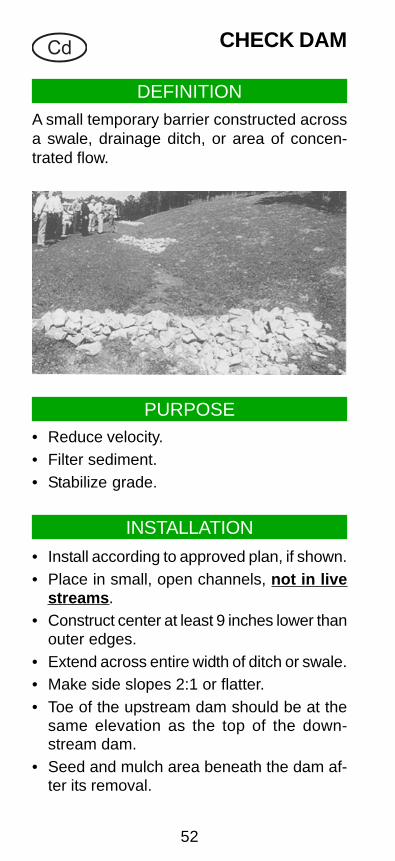
A small temporary barrier constructed acrossa swale, drainage ditch, or area of concen-trated flow.
PURPOSE• Reduce velocity.• Filter sediment.• Stabilize grade.
INSTALLATION
• Install according to approved plan, if shown.• Place in small, open channels, not in live
streams.• Construct center at least 9 inches lower than
outer edges.• Extend across entire width of ditch or swale.• Make side slopes 2:1 or flatter.• Toe of the upstream dam should be at the
same elevation as the top of the down-stream dam.
• Seed and mulch area beneath the dam af-ter its removal.
53
Stone Check Dams Cd-S
• Drainage area not to exceed 2 acres.• Constructed of graded size 2"-10" stone.• 2 feet maximum dam height measured to
center of check dam.• Place a suitable geotextile between the
rock and its soil base and abutments.
Cd
MAINTENANCE• Periodic inspection and maintenance re-
quired.• Remove sediment when it reaches a depth
of one-half the original dam height.• Remove at the completion of its useful life.
REFERENCES
• Ds1 Disturbed Area Stabilization(With mulching only)
• Ds2 Disturbed Area Stabilization(With temporary seeding)
• Ds3 Disturbed Area Stabilization(With permanent seeding)
• Ds4 Disturbed Area Stabilization(With sodding)
Figure 1. Stone Check Dam InstallationRequirements
Dam A
2"-10" stone
Geotextileunderliner
24" maximumheight
Dam B
Elevation of top of Dam A
Elevation of bottom of Dam B
equals
Flow
9"
54
Ch CHANNELSTABILIZATION
DEFINITION
Improving, constructing, or stabilizing an openchannel or waterway.
PURPOSE
• Prevent erosion and sediment deposition.• Provide adequate capacity for flood water,
drainage, or other water management prac-tices.
INSTALLATION• Install according to approved plan, if shown.• Drainage area not to exceed one square
mile.• Establish or install immediately after con-
struction or as soon as weather permits.
Vegetative Lining Ch-V
• Permanent or temporary vegetation maybe used.
• Install erosion control blankets, if required.
55
Rock Riprap Lining Ch-Rp
• Slopes should be 1.5:1 or less.• Place a filter blanket, at least 6 inches
thick, of sand, gravel, and/or geotextilematerial between the riprap and the basematerial.
Concrete Lining Ch-C
• For channels where velocities exceed 10feet per second.
Grade Stabilization Structure• Constructed of concrete, rock, masonry,
steel, aluminum or treated wood.• Provide adequate outlet for discharge.• Do not compromise the environmental in-
tegrity of the area.• Vegetate all disturbed areas immediately.
Ch
MAINTENANCEPeriodic inspection and maintenance required.
REFERENCES
• Gr Grade Stabilization Structure
• Ds1 Disturbed Area Stabilization(With mulching only)
• Ds2 Disturbed Area Stabilization(With temporary seeding)
• Ds3 Disturbed Area Stabilization(With permanent seeding)
• Ds4 Disturbed Area Stabilization(With sodding)
56
Co CONSTRUCTIONEXIT
DEFINITION
A stone-stabilized pad located at any pointwhere traffic will be leaving a construction siteto a public right-of-way, street, alley, sidewalk,or parking area.
PURPOSE
Reduce or eliminate the transport of mud fromthe construction area.
INSTALLATION
• Install according to approved plan, if shown.• Use 1.5"-3.5" stone.• Minimum pad thickness of 6 inches.• Minimum pad width of 20 feet.• Minimum pad length of 50 feet.• Excavate footprint 3 inches.• If tire washing is required, route runoff from
washing to an approved sediment trap orsediment basin.
• Install filter fabric under the entire pad.
57
Co
MAINTENANCE
• Periodically dress with 1.5"-3.5" stone.• Maintain in a condition that will prevent track-
ing or flow of mud onto public rights-of way.• Immediately remove mud and debris tracked
or spilled onto roadways.
Figure 1. Crushed Stone ConstructionExit Installation Requirements
Hard SurfecePublic Road
6" Minimum
N.S.A. R-2(1.5"-3.5")
Coarse Aggregate
Geotextile Underliner 20' Minimum
50' Minimum
Figure 2. Geotextile Underliner UnderGravel Pad
58
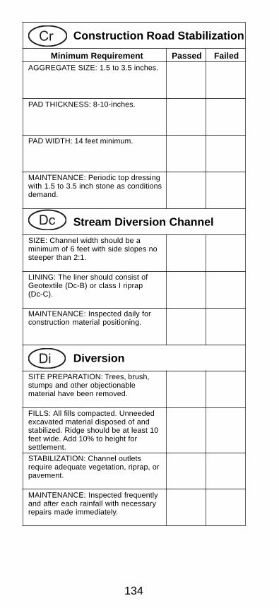
Cr CONSTRUCTIONROAD
STABILIZATION
DEFINITION
A travel way constructed as part of a construc-tion plan including access roads, subdivisionroads, parking areas, and other on-site vehicletransportation routes.
PURPOSE
To provide a fixed route of travel for construc-tion traffic and to reduce erosion and subse-quent regrading of permanent roadbeds be-tween time of initial grading and final stabili-zation.
INSTALLATION
• Install according to approved plan.• Temporary roads shall follow the contours
of the natural terrain to minimize disturbanceof drainage patterns.
• If a temporary road must cross a stream,the crossing must be designed, installed andmaintained according to temporary streamcrossing (Sr) specifications.
59
Cr
• Grades for temporary roads should not ex-ceed 10 per cent except for short lengthswith a maximum of 20 per cent for specialuses.
• Temporary roadbeds shall be at least 14 feetwide for one-way traffic, 20 feet wide for two-way traffic, and 24 feet wide for trailer traf-fic.
• All cut and fills shall have side slopes at amaximum of 2:1 or 3:1 if mowing is planned.
• Drainage channels shall be designed to beon stable grades or protected with structuresor linings for stability.
• Geotextile should be applied to the road-bed for additional stability according to thedesign manual specifications.
• A 6-inch layer of coarse aggregate shall beapplied immediately after grading.
MAINTENANCE
Roads and parking areas may require a peri-odic top dressing of gravel to maintain thegravel depth at 6 inches. Vegetated areasshould be checked periodically to ensure agood stand of vegetation is maintained. Re-move any silt or other debris causing cloggingof roadside
REFERENCES
• Sr Temporary Stream Crossing
60
Dc STREAM DIVERSIONCHANNEL
DEFINITION
A temporary channel constructed to conveyflow around a construction site while a per-manent structure is being constructed in thestream channel.
PURPOSE
To protect the streambed from erosion andallow work “in the dry”.
A
FLOW
FORMER LOCATIONOF FLOW BARRIER
FLO
W
VEHICULAR STREAM
PLACE
FLOW BARRIER
ORIGINAL
FLOW BARRIER(RIPRAP, SANDBAGS,PLYWOOD, JERSEYBARRIERS OR SHEETPILING)
PLACE RIPRAPAT TRANSITION
STREAM-BED
RIPRAPATTRANSITION
FORMER LOCATION
FLOW
SILT FENCEOF FLOW BARRIER
CROSSING.(TO BE LOCATED ATORIGINAL STREAMBEDFOR INITIAL CROSSINGS)
• Install according to approved plan.• Drainage area not to exceed one square
mile (640 acres).• The bottom width of the stream diversion
shall be a minimum of six feet or equal tothe bottom width of the existing streambed,whichever is greater.
• Side slopes of the stream diversion chan-nel shall be no steeper than 2:1.
• Depth and grade of the channel shall besufficient to ensure continuous flow of wa-ter in the diversion.
• The channel shall be lined to prevent ero-sion of the channel and sedimentation inthe stream. The lining is selected basedupon the expected velocity of bankfull flow.The linings are as follows:
1)Geotextile, polyethylene film or sod
Dc-A for a velocity range of 0-2.5 fps.
2)Geotextile alone Dc-B for a velocityrange of 2.5-9.0 fps.
3)Class I riprap and geotextile Dc-C for avelocity range of 9.0-13.0 fps.
• The channel shall be excavated, construct-ing plugs at both ends.
• Silt fence or berms shall be placed alongthe sides of the channel to prevent unfilteredrunoff from entering the stream.
• The channel surface shall be smooth (toprevent tearing of the liner) and lined withthe material specified in the plans.
• The plugs are removed when the liner in-stallation is complete, removing the down-stream plug first.
62
Dc
• As soon as construction in the streambedis complete, the diversion shall be repluggedand backfilled.
• Upon removal of the lining, the stream shallimmediately be restored and properly sta-bilized.
• All other appropriate agencies, including theCOE, must be contacted to ensure compli-ance with other Laws.
MAINTENANCE
The stream diversion channel shall be in-spected at the end of each day to make surethat the construction materials are positionedsecurely. This will ensure that the work areastays dry and that no construction materialsfloat downstream. All repairs shall be madeimmediately.
REFERENCES
• Mb Erosion Control Matting and Blankets
(This page left blank intentionally.)
63
64
Di DIVERSION
DEFINITION
A ridge of compacted soil, constructed above,across, or below a slope.
PURPOSE
• Reduce slope lengths.• Intercept and divert storm runoff to a stable
outlet at a non-erosive velocity.
INSTALLATION
• Install according to approved plan, if shown.• Remove trees, brush, stumps and other ob-
jectionable material.• Compact all fills.• Channel cross-section should be trapezoi-
dal or parabolic in shape.• Side slopes should be 2:1 or flatter.• Excavate narrow, deep channels on steep
slopes and broad, shallow channels ongentle slopes.
• Adequate outlet must be present.
65
Di
• Stabilize channel and outlet with vegetation(mulch required for all seeded or spriggedchannels), riprap, or pavement.
• Dispose of and/or stabilize unneeded ex-cavated material.
MAINTENANCE
Inspect frequently and after each rainfall andmake necessary repairs.
REFERENCES
• Ds1 Disturbed Area Stabilization(With mulching only)
• Ds2 Disturbed Area Stabilization(With temporary seeding)
• Ds3 Disturbed Area Stabilization(With permanent seeding)
• Ds4 Disturbed Area Stabilization(With sodding)
ExcavatedChannel
8"-12"
8"-12"
6'-12'
Road Surface
Original
Figure 1. Typical Diversion Across Road
66
Dn1 TEMPORARYDOWN DRAINSTRUCTURE
DEFINITION
A temporary structure used to convey stormwater down the face of cut or fill slopes.
PURPOSE• Transport storm runoff from one elevation
to another.• Reduce slope erosion.
INSTALLATION• Install according to approved plan, if shown.• Install heavy-duty, flexible materials such as
non-perforated, corrugated plastic pipe.
67
• Place on undisturbed soil or well-compactedfill.
• Install tee, “L” or flared end section inlet atthe top of the slope.
• Entrance sloped 1/2" per foot toward inlet.• Compact a dike ridge no less than one foot
above the top of the pipe.• Anchor with hold-down grommets or stakes
at intervals not to exceed 10 feet.• Ensure connections are watertight.• Extend pipe beyond the toe of the slope.• Direct outlet uphill.• Stabilize outlet with tee, riprap or other suit-
able material.• Vegetate all disturbed areas immediately.• See Figure 1.
Dn1
MAINTENANCE• Inspect drain and diversion after every rain-
fall and promptly make necessary repairs.• Remove once the permanent water disposal
system is installed.
REFERENCES
• St Storm Drain Outlet Protection
Table 1. Pipe Diameter for TemporaryDowndrain
Maximum Drainage Pipe DiameterArea per Pipe (inches)
(acres)
0.3 10
0.5 12
1.0 18
68
Dn1
Figure 1. Temporary Downdrain and InletDetail
Dive
rsion
chan
nel
1.5'm
in
4'min
3:1
Flow
Hold-
down
stake
s
Dive
rsion dike
1' mi
n heig
ht
Undis
turbe
d soil
orwe
ll-com
pacte
d fill
10' maximun spacing
Corru
gated
plasti
c pipe
Stab
ilized
outle
t
4' mi
n
level
secti
on
Flow
Norm
al gro
und l
evel
(This page left blank intentionally.)
69
70
Dn2 PERMANENTDOWN DRAINSTRUCTURE
DEFINITION
A permanent structure to safely convey sur-face runoff from the top of a slope to the bot-tom of the slope.
PURPOSE
Minimize erosion due to concentrated stormrunoff on cut or fill slopes.
INSTALLATION
• Install according to approved plan, if shown.• Types of Structures
• Pipe: steel, plastic, etc.• Sectional: a prefabricated sectional con-
duit of half-round or third-round pipe.• Slopes must have sufficient grade to pre-
vent sediment deposition.• Stabilize outlet according to plans.• Vegetate all disturbed areas immediately.
71
Dn2
MAINTENANCE
Periodic inspection and maintenance required.
REFERENCES
• St Storm Drain Outlet Protection
• Ds1 Disturbed Area Stabilization(With mulching only)
• Ds2 Disturbed Area Stabilization(With temporary seeding)
• Ds3 Disturbed Area Stabilization(With permanent seeding)
• Ds4 Disturbed Area Stabilization(With sodding)
Flow
Flow
Stabilized outlet
Figure 1. Typical Concrete Paved Flume
72
Fr FILTER RING
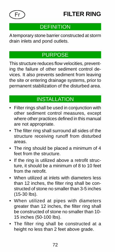
DEFINITION
A temporary stone barrier constructed at stormdrain inlets and pond outlets.
PURPOSE
This structure reduces flow velocities, prevent-ing the failure of other sediment control de-vices. It also prevents sediment from leavingthe site or entering drainage systems, prior topermanent stabilization of the disturbed area.
INSTALLATION
• Filter rings shall be used in conjunction withother sediment control measures, exceptwhere other practices defined in this manualare not appropriate.
• The filter ring shall surround all sides of thestructure receiving runoff from disturbedareas.
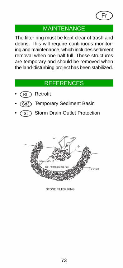
• The ring should be placed a minimum of 4feet from the structure.
• If the ring is utilized above a retrofit struc-ture, it should be a minimum of 8 to 10 feetfrom the retrofit.
• When utilized at inlets with diameters lessthan 12 inches, the filter ring shall be con-structed of stone no smaller than 3-5 inches(15-30 lbs).
• When utilized at pipes with diametersgreater than 12 inches, the filter ring shallbe constructed of stone no smaller than 10-15 inches (50-100 lbs).
• The filter ring shall be constructed at aheight no less than 2 feet above grade.
73
Fr
MAINTENANCE
The filter ring must be kept clear of trash anddebris. This will require continuous monitor-ing and maintenance, which includes sedimentremoval when one-half full. These structuresare temporary and should be removed whenthe land-disturbing project has been stabilized.
REFERENCES
• Rt Retrofit
• Sd3 Temporary Sediment Basin
• St Storm Drain Outlet Protection
Minimum 8' - 10'
50# - 150# Stone Rip-Rap2'-0" Min.
STONE FILTER RING
74
Ga GABION
DEFINITIONLarge, multi-celled, rock-filled wire mesh boxesused in channel revetments, retaining walls,abutments, check dams, etc.
PURPOSE• Construction of erosion control structures.• Stabilize steep or highly erosive slopes.
INSTALLATION
• Install according to approved plan, if shown.• Foundations must be smooth and level.• Only galvanized or PVC coated wire should
be used.• Set individual baskets into place, wire them
together in courses, and fill with rock to formflexible monolithic building blocks.
• Rock should be durable and adequatelysized (normally 4"-8") to be retained in thebaskets.
• “Key” structure securely into foundationsand abutment surfaces.
75
Ga
MAINTENANCEPeriodically inspect for signs of undercuttingor excessive erosion at transition areas, andmake necessary repairs immediately.
76
Gr GRADESTABILIZATION
STRUCTURE
DEFINITION
A structure to stabilize the grade in natural orartificial channels.
PURPOSE• Stabilize the grade in natural or artificial
channels.• Prevent the formation or advancement of
gullies.• Reduce erosion and sediment pollution.
INSTALLATION• Install according to approved plan, if shown.• Construct with concrete, rock, masonry,
steel, aluminum, or treated wood.• Dewater excavations prior to filling.• Construct minimum top width of 10 feet with
side slopes of 3:1 or flatter on earthfill em-bankments that are constructed in 6" to 8"horizontal lifts.
• Compact fill to approximately 95 percent ofstandard density.
• Construct keyway 8 or more feet wide and2 feet deep along centerline of the struc-ture and embankment.
77
Gr
MAINTENANCE
Periodic inspection and maintenance required.
REFERENCES
• St Storm Drain Outlet Protection
• Ds1 Disturbed Area Stabilization(With mulching only)
• Ds2 Disturbed Area Stabilization(With temporary seeding)
• Ds3 Disturbed Area Stabilization(With permanent seeding)
• Ds4 Disturbed Area Stabilization(With sodding)
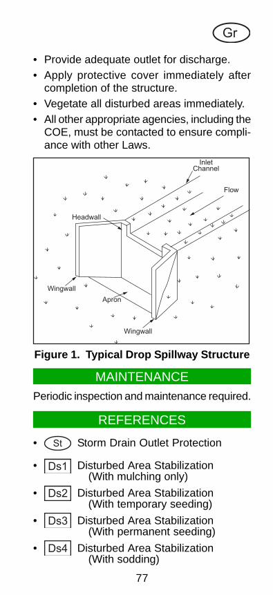
• Provide adequate outlet for discharge.• Apply protective cover immediately after
completion of the structure.• Vegetate all disturbed areas immediately.• All other appropriate agencies, including the
COE, must be contacted to ensure compli-ance with other Laws.
Wingwall
Apron
Wingwall
Headwall
Flow
InletChannel
Figure 1. Typical Drop Spillway Structure
78
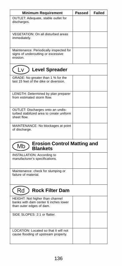
Lv LEVEL SPREADER
DEFINITION
An outlet device constructed at zero gradeacross the slope where concentrated runoffmay be discharged at non-erosive velocitiesonto undisturbed areas stabilized by existingvegetation.
PURPOSE
• Minimize erosion.• Convert concentrated storm runoff to sheet
flow.• Guide storm runoff to an undisturbed, veg-
etated area.
INSTALLATION
• Install according to approved plan, if shown.• Grade the channel no greater than 1% for
the last 15 feet of the dike or diversion.• Construct on undisturbed soil that is stabi-
lized with vegetation.• Minimum width of 6 feet.• Minimum, uniform depth of 6 inches as mea-
sured from the lip.• Uniform depth across the entire length.
79
• Level lip constructed on zero percent grade.• Discharge onto an undisturbed, stabilized
area at zero grade.• Provide a smooth outlet.• Prevent water from concentrating below
point of discharge.• Vegetate all disturbed areas immediately.
Lv
MAINTENANCE
Periodic inspection and maintenance is re-quired.
REFERENCES
• Ds1 Disturbed Area Stabilization(With mulching only)
• Ds2 Disturbed Area Stabilization(With temporary seeding)
• Ds3 Disturbed Area Stabilization(With permanent seeding)
• Ds4 Disturbed Area Stabilization(With sodding)
Figure 1. Level Spreader InstallationRequirements
STABILIZEDSLOPE
TRANSITIONTO 0 GRADE
VEGETATED
DIVERSION
STABLE
UNDISTURBED
OUTLET
80
Rd ROCK FILTER DAM
DEFINITION
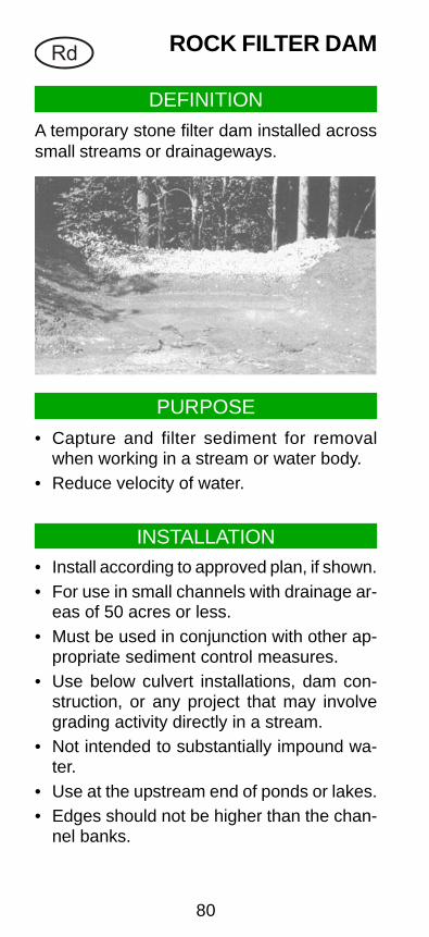
A temporary stone filter dam installed acrosssmall streams or drainageways.
PURPOSE
• Capture and filter sediment for removalwhen working in a stream or water body.
• Reduce velocity of water.
INSTALLATION• Install according to approved plan, if shown.• For use in small channels with drainage ar-
eas of 50 acres or less.• Must be used in conjunction with other ap-
propriate sediment control measures.• Use below culvert installations, dam con-
struction, or any project that may involvegrading activity directly in a stream.
• Not intended to substantially impound wa-ter.
• Use at the upstream end of ponds or lakes.• Edges should not be higher than the chan-
nel banks.
81
Rd
MAINTENANCE• Requires periodic inspection and mainte-
nance.• Sediment removed when it reaches one-half
of the original dam height.• Remove at the completion of its useful life.
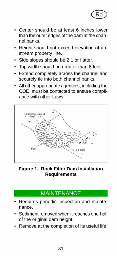
• Center should be at least 6 inches lowerthan the outer edges of the dam at the chan-nel banks.
• Height should not exceed elevation of up-stream property line.
• Side slopes should be 2:1 or flatter.• Top width should be greater than 6 feet.• Extend completely across the channel and
securely tie into both channel banks.• All other appropriate agencies, including the
COE, must be contacted to ensure compli-ance with other Laws.
Figure 1. Rock Filter Dam InstallationRequirements
Larger stone installedaccording to plan
Flow3 - 5 lb stone
6'minwidth
82
Re RETAINING WALL
DEFINITION
A constructed wall of one or more of the fol-lowing: concrete masonry, reinforced concretecribbing, treated timbers, steel pilings, ga-bions, stone drywall, rock riprap, etc.
PURPOSETo assist in stabilizing cut or fill slopes wherestability could only be obtained with the useof a wall.
INSTALLATIONRetaining walls require specific designs whichare within the capabilities of a design engi-neer or a licensed architect. Close supervi-sion is required to ensure proper installation.
Figure 1. Typical Stone Retaining Wall
(This page left blank intentionally.)
83
84
Rt RETROFITTING
DEFINITION
A device placed in front of an outlet structureto temporarily filter sediment.
PURPOSE
Allow stormwater detention basins to functionas temporary sediment retention basins.
INSTALLATION
• Install according to approved plan, if shown.• Prohibited in detention basins on live
streams.• Install on approximately 1/2 the height of
the outlet structure.
Perforated Half-Round Pipe with Stone FilterRt-P
• Half-round pipe diameter should be 1.5times the diameter of the principal pipeoutlet or wider than the greatest width ofthe concrete weir.
• Attach to the outlet structure, but neveruse on exposed pipe end or wingedheadwall.
• Drainage area not to exceed 30 acres.• See Figures 1 and 2.
85
Rt
Stone Filter Ring• Use in conjunction with half-rounds or
board dams.• Minimum height of 2'.• Minimum distance of 8' to 10' between
retrofit and ring.• Pipe with diameter larger than 12" re-
quires 10"-15" stone, faced with smallerfilter stone.
Figure 1. Perforated Half-Round PipeRetrofit with Stone Filter.
Flow
Flow
See Figure 2 for an exploded view of this structure.
86
RtF
low
Flo
w
1/2
" T
hrd
. R
od
with n
uts
and w
ashers
(an
cho
red
to
wa
ll)
Ha
lf-r
ou
nd
CM
Pattached to w
eir
top
of
pip
e (
1' m
in w
idth
)3
" -
4"
sto
ne
e
ve
n
1'
ho
es
8' -
10
" a
pa
rt
Ap
ron
o
rco
ncr
ete
bo
tto
m
L-
2"
x2"
x1/
4"
Figure 2. Perforated Half-Round PipeRetrofit with Stone Filter Installation
Requirements
87
Slotted Board Dam with Stone Rt-B
• Can be used with open pipe ends, wingedheadwalls, or concrete weir outlets.
• Install with 4x4" or larger posts with 0.5"to 1" spacing.
• Drainage area not to exceed 100 acres.• Can excavate in front of the retrofitted
outlet structure or raise the outlet struc-ture to obtain required sediment storage.
Rt
MAINTENANCE• Clean-out when one-third sediment storage
capacity is lost. Indicate this elevation witha mark on the outlet structure or a post in-serted in the pond.
• Remove all trash and debris.• Remove retrofit and accumulated sediment
when the project is completed.• Stabilize all disturbed areas immediately
with permanent vegetation.
Figure 3. Slotted Board Dam InstallationRequirements
Flow4" x 4" posts
2" x 4" boards0.5"- 1" spacing
3"- 4" stoneeven with top
88
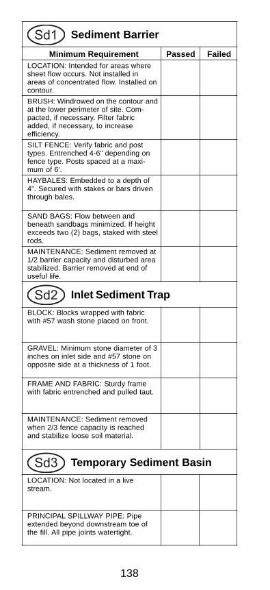
Sd1 SEDIMENT BARRIER
DEFINITION
A temporary structure made of silt fence sup-ported by steel or wood posts, sandbags,straw bales or other filtering material.
PURPOSE
• Install according to approved plan, if shown.• Install along contours with ends pointing
uphill.• Do not place in waterways or areas of con-
centrated flow.
Sandbags Sd1-S
• Flow under or between bags should beminimal.
• Anchoring with steel rods may be requiredif height exceeds two bags.
INSTALLATION
• Slow the velocity of runoff and cause sedi-ment deposition at the structure.
• Filter sediment from runoff.
89
Sd1
Hay or Straw Bales Sd1-Hb
• Place in a single row, lengthwise, on thecontour.
• Embed in the soil to a depth of 4 inches.• Secure with stakes or bars driven through
the bales or by other adequate means.• Place in areas of low rate sheet flow.• For use on projects with a duration of
three months or less.
Brush (use during timber clearing operations)
Sd1-Bb
• Pile in a row along the perimeter of land-disturbing activities.
• Windrow on the contour as close as pos-sible.
• Compaction may be required.• Filter fabric may be placed on the con-
struction side of the brush barrier foradded filtering capacity. Lower edge mustbe entrenched 4 to 6 inches deep. Theupper edge must be fastened to the brushbarrier.
Silt Fence Sd1-A Sd1-B Sd1-C
• Install where sheet flow conditions exist.• Drainage area is not to exceed 1/4 acre
• Inspect, clear, and/or repair trap at the endof each working day.
• Do not remove inlet protection and washsediment into the storm drain.
• Remove sediment from the trap and stabi-lize it with vegetation.
• Remove all materials and any unstable soilonce the contributing drainage area hasbeen adequately stabilized.
• Appropriately stabilize all bare areas aroundthe inlet.
REFERENCES
• Sd1 Sediment Barrier
(This page left blank intentionally.)
99
100
Sd3 TEMPORARYSEDIMENT BASIN
DEFINITION
A basin created by excavation or the construc-tion of a dam for sediment collection.
PURPOSE
• Detain runoff waters and trap sediment.• Protect properties and drainageways below
the basin from damage by excessive sedi-mentation and debris.
INSTALLATION
• Install according to approved plan, if shown.• Length to width ratio shall be greater than
2:1, where length is the distance betweenthe inlet and outlet.
101
Sd3
Location• Must never be placed in a live stream.• Storm drains should discharge into the
basin.• Install on sites where (1) failure will not
result in loss of life or interruption of useor service of public utilities and (2) thedrainage area does not exceed 150 acres.
Principal Spillway• Join vertical pipe or box type riser to a
pipe that extends through the embank-ment and exits beyond the downstreamtoe of the fill.
• Perforate lower half of riser with 1/2 inchholes spaced approximately 3 inches, andcover with two feet of 1/2 to 3/4 inch ag-gregate.
• Install pipe with a minimum diameter of 8inches.
• Equip with a trash rack and anti-vortexdevice.
Inflow
Trash rack
Earthen dam
Gravel filter
Perforatedriser pipe
Concreteriser base
Outflow
Em
ergency Spillw
ay
Figure 1. Components of a TypicalTemporary Sediment Basin
102
Sd3
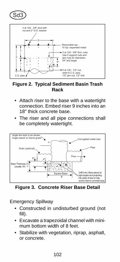
• Attach riser to the base with a watertightconnection. Embed riser 9 inches into an18" thick concrete base.
• The riser and all pipe connections shallbe completely watertight.
Emergency Spillway• Constructed in undisturbed ground (not
fill).• Excavate a trapezoidal channel with mini-
mum bottom width of 8 feet.• Stabilize with vegetation, riprap, asphalt,
or concrete.
Figure 2. Typical Sediment Basin TrashRack
3 at 120 - 3/8" stud withnut and 2" O.D. washer
D
8"
2'
1'
1'
C.S. pipe
Removable top -10 Ga. expanded metal
3 at 120 - 5/8" thrd. rods;Use 5 support rods andjam nuts for diameters54" and larger
3 at 120 - 1/2" nut,weld to C.S. pipe;1/2" jam nut, 1/2" bolt
Figure 3. Concrete Riser Base Detail
9"
Drain (optional)
Angle the stub to be shownAngle based on barrel grade
Base Thickness (T)(usually 18')
4"
Corrugated metal riser
Pipe
Flow
2-#6 (min.) Bars placed atright angles and projectinginto sides of riser to helpanchor riser to concrete base.
Square Base
B
103
Sd3
Entrance of Runoff into Basin• Install dikes, swales, or other water con-
trol devices to direct runoff into the ba-sin.
• Locate points of entry as far away fromthe riser as possible.
• Stabilize with permanent vegetation imme-diately following construction.
• Remove sediment when storage volumehas been reduced by one-third.
• Dispose and stabilize sediment beyond thereach of the pond.
• Do not deposit sediment downstream fromthe embankment, adjacent to a stream orfloodplain.
MAINTENANCE
Figure 4. Section Through Embankmentand Typical Features
TrashrackFlood pool
Emergency spillway crest
Freeboard - 1' min
2.5:1 or flatter
Embankment stabilizedwith vegetation
StabilizedoutletCut-off trench
2' deep, min.
1:1
1' min.
Principalspillwaypipe
Selected fillplaced in layersand compacted
Anti-flotationblock
1/2" drainageholes with gravel#57 or #5 clean
Riser pipefor principalspillway
Anti-seepcollar
Table 1. Sediment Basin Dam WidthRequirements
Fill Height Minimum Top Width
Less than 10 feet 8.0 feet
10 to 15 feet 10.0 feet
104
Sd3
• St Storm Drain Outlet Protection
• Ds1 Disturbed Area Stabilization(With mulching only)
• Ds2 Disturbed Area Stabilization(With temporary seeding)
• Ds3 Disturbed Area Stabilization|(With permanent seeding)
• Ds4 Disturbed Area Stabilization(With sodding)
REFERENCES
• Indicate clean-out elevation with a mark onthe riser or by a marked post near the riser.
• Do not remove basin until the sediment-pro-ducing area is permanently stabilized.
(This page left blank intentionally.)
105
106
Sr TEMPORARYSTREAM CROSSING
DEFINITION
A temporary structure installed across a flow-ing stream or watercourse for use by construc-tion equipment.
PURPOSE
Protect streams from damage and erosion.
INSTALLATION
• Install according to approved plan, if shown.• Includes bridges Sr-B , round pipes or pipe
arches Sr-C .• Drainage area not to exceed one square
mile.• Minimize clearing and excavation of the stre-
ambed and banks.• Cross very small streams with armored, pro-
tected fords, such as rock riprap.• Elevate crossing to reduce the possibility of
washout from a 25-year peak discharge.• Convey full bank flow without appreciably
altering or restricting stream flow habits.
107
Sr
• Washout protection may include elevationof bridges above adjacent flood plain lands,crowning of fills over pipes, or the use ofdiversions, dikes or island type structures.
• Reduce the velocity of flow from storm drainoutlets.
• Reduce erosion of receiving channels.• Stabilize grades.
INSTALLATION
• Install according to approved plan, if shown.• Place a filter blanket or filter fabric between
riprap and soil foundation.• Install a graded gravel layer if geotextile is
not used.• Line with riprap, grouted riprap, or concrete.
Use field or quarry stone with minimum di-ameter of 6 inches for riprap.
• Minimum apron thickness should be 1.5times the maximum stone diameter.
• Extend apron length to at least six timesthe outlet pipe diameter.
111
St
Apron Width for a Well-Defined Channel• Side slopes of the channel no steeper
than 2:1.• Apron extends across the channel bot-
tom.• Apron extends up the channel banks to
an elevation one foot to the top of thebank.
Apron Width for a Flat Area• Upstream width three times the diameter
of the outlet pipe.• Downstream width three times the diam-
eter of the outlet pipe plus the length ofthe apron.
• Construct apron at zero grade with nooverfall at the end.
• Conform to bottom grade of receivingchannel.
Figure 1. Outlet Protection for a Well-Defined Channel
Filter blanketor
filter fabric
Soil foundation
d
Apron extends to topof channel bank(or 6" above the max tailwaterdepth, whichever is less.)
112
St
MAINTENANCE
• Inspect after heavy rains for erosion and dis-lodged stones.
• Make all repairs immediately.
Figure 2. Outlet Protection for a FlatArea
d
L=6d minimum
W=3d minimum
Filter blanketor
filter fabric
Soil foundation
6"min depth
W
L
• Locate to prevent bends in horizontalalignment.
• Place necessary curves in the upper sec-tion of the apron.
• Vegetate all disturbed areas immediately.
(This page left blank intentionally.)
113
114
Su SURFACEROUGHENING
DEFINITIONProviding a rough soil surface on the contour.
PURPOSE• Aid in establishment of vegetative cover with
seed.• Reduce runoff velocity and increase infiltra-
tion.• Reduce erosion and provide for sediment
trapping.
INSTALLATION• Apply according to approved plan, if shown.• Not required on slopes with a stable rock
face.• Stair-step, groove, furrow, or track slopes
that are to be vegetated.• Lightly roughen and loosen soil to a depth
of 2"-4" on slopes 3:1 or flatter.• Slopes requiring mowing shall not be
steeper than 3:1.• Groove or maintain roughness of fill slopes
steeper than 3:1.• Stair-step or groove cut slopes steeper than
3:1.
115
Stair-Step Grading• Particularly good for slopes with soft rock.• Vertical cut distance to horizontal distance
shall be less than 1:1. Horizontal portionof the “step” shall slope toward the verti-cal wall.
• Individual vertical cuts are not to exceed30 inches on soft materials and not morethan 40 inches in rocky materials.
Su
Figure 2. Typical Stair-Step Grading
Figure 1. Stair-Stepping Cut Slopes
Water, soil, and fertilizerare held by steps - plantscan become established onthe steps.
40" - 50"
maximum
Drainage
Debris from slope aboveis caught by steps
ma
xim
um
30
" -
40
"
116
Grooving• Use discs, tillers, spring harrows, or the
teeth on a front-end loader.• On unmowed slopes, minimum groove
depth of 3 inches and maximum groovespacing of 15 inches.
• On mowed slopes, minimum depth of oneinch and maximum groove spacing of 12inches.
Su
Figure 3. Grooving Slopes
Grooving is cutting furrows
along the conyour of a slope.
Irregularities in the soil surface
provide some coverage of lime,
fertilizer and seed.
13"-15
" max
imum
min
imum
3"
117
Su
Tracking• Not recommended unless no alternatives
are available.• Minimize machine passes to minimize
compaction.
Figure 4. Roughening with TrackedMachinery
Dozer treads create
grooves perpeddicular
to the slope.
TRACKING
Slope
Figure 5. Fill Slope Treatment
Each lift of the fill is compacted, but the outer face
of the slope is allowed to remain lose so that the rocks,
clods, etc. reach the natural angle of repose.
• Seed and mulch roughened areas as soonas possible.
118
Tp TOPSOILING
DEFINITION
Stripping-off the fertile top soil, storing it, thenspreading it over the disturbed area after con-struction is completed.
PURPOSE
Provide a suitable soil medium for vegetativegrowth on low fertility areas.
SPECIFICATIONS
• Apply according to approved plan, if shown.• Recommended for sites with slopes 2:1 or
flatter where:• the texture of the exposed subsoil or par-
ent material is not suitable to produceadequate vegetative growth,
• the root zone is too shallow, or• the soil to be vegetated contains mate-
rial toxic to plant growth.• Topsoil should be friable and loamy, free of
debris, objectionable weed and stones, andcontain no toxic substance that may beharmful to plant growth.
119
• Stripping depth of 4 to 6 inches is commonand should be confined to the immediateconstruction area.
• Stockpiles may be vegetated and should notobstruct natural drainage or cause off-siteenvironmental damage.
• If subsoil is composed of heavy clays, limeshall be spread at the rate of 100 poundsper 1,000 square feet.
• Subsoil should be loosened by discing orscarifying to a minimum depth of 3 inchesto permit bonding of the topsoil to the sub-soil. Tracking by a bulldozer is also ad-equate.
• Topsoil should be applied at a uniform depthof 5 inches (unsettled), but may be adjustedat the discretion of the engineer or land-scape architect.
Tp
Table 1. Cubic Yards of Topsoil Requiredfor Application to Various Depths
Depth Per 1,000(inches) Square Feet Per Acre
1 3.1 134
2 6.2 268
3 9.3 403
4 12.4 537
5 15.5 672
6 18.6 806
120
Wt VEGETATED WATERWAYOR STORMWATER
CONVEYANCE CHANNEL
DEFINITION
A waterway that is shaped or graded to re-quired dimensions and stabilized with vegeta-tion.
PURPOSE
• Install according to approved plan, if shown.• Remove all woody growth, obstructions and
other objectionable material.• Waterway cross-section may be parabolic
or trapezoidal in shape.• Maximum permissible velocity within a veg-
etated channel is approximately 5 feet persecond without geosynthetic material.
• Dispose of stormwater runoff.• Prevent erosion.• Reduce sedimentation.
INSTALLATION
121
Wt
• Maximum bottom width of 50 feet unlessmultiple or divided waterways or othermeans are provided to control meanderingof low flows within this limit.
Table 1. Permissible Velocities forVegetated and Rock-Lined Waterways
Bermuda 5
Bahia 4
Tall Fescue 4
Sericea LespedezaWeeping Lovegrass 3
Stone center Design required
Vegetative MaximumCover Permissible Velocity
(fps)
• Tile or other subsurface drainage measureshall be provided for sites having high wa-ter tables or seepage problems. Where thereis base flow, a stone center or lined chan-nel may be required.
122
• Disturbed areas must be stabilized with veg-etation immediately following construction.
• Mulching is required for all seeded orsprigged channels.
• Erosion control fabrics which are designedto protect seed and slopes during the es-tablishment of vegetation shall be used.
• If conditions permit, water should be tem-porarily diverted from the channel, or oth-erwise disposed of, during the establish-ment of vegetation.
Wt
REFERENCES
• Ds1 Disturbed Area Stabilization(With mulching only)
• Ds2 Disturbed Area Stabilization(With temporary seeding)
• Ds3 Disturbed Area Stabilization(With permanent seeding)
• Ds4 Disturbed Area Stabilization(With sodding)
(This page left blank intentionally.)
123
124
HISTORY
O.C.G.A. 12-7-1The Erosion and
Sedimentation Act of 1975as Amended
AGENCIES
Georgia’s Erosion and Sedimentation Act waspassed in 1975 and became effective in 1977.It has been amended several times; in 1980,1985, 1989, 1994, 1995 and 2000. The 1994and 1995 amendments were significant in thatthe emphasis is now on Best ManagementPractices (BMPs) instead of water quality.
This law specifically defines the duties of fourseparate and distinct agencies:
1. Local Issuing Authority (LIA).
2. The Environmental Protection Division(EPD) of the Department of Natural Re-sources (DNR).
3. The Soil and Water Conservation District(SWCD).
4. The State Soil and Water ConservationCommission (SSWCC).
Unnamed, but critically important to the pro-gram, is the Natural Resource ConservationService (NRCS) of the US Department of Ag-riculture (USDA).
125
LAND-DISTURBING ACTIVITIESThe Law defines a land-disturbing activity as:
“Any land change which may resultin soil erosion from water or wind andthe movement of sediments into StateWater or onto lands within the Stateincluding, but not limited to clearing,dredging, grading, excavating, trans-porting, and filling.”
EXEMPTEDLAND-DISTURBING ACTIVITIES
The Law contains certain exemptions. Permitsfor land-disturbing activities are not requiredfor the following:
1. Surface mining.
2. Granite quarrying.
3. Minor land-disturbing activities such ashome gardens, home landscaping, etc.
City and County governments may becomeLIAs by adopting ordinances and enforcingprovisions of the Law for specific land-disturb-ing activities (LDA). By becoming a LIA, thelocal government may also issue LDA permits.Otherwise, the EPD will have permitting, in-spection and enforcement authority within thelocal government’s jurisdiction. Most metrogovernments have elected to become issuingauthorities along with over 80 percent of thecounties. Among smaller towns and cities, over40 percent are issuing authorities. In fact, over90 percent of Georgia’s population resideswhere local governments have that responsi-bility.
CERTIFICATION AS ALOCAL ISSUING AUTHORITY
126
4. Construction of single-family residencesfor or by the owner.
5. Agricultural Practices.
6. Forestry Practices.
7. Projects of the Natural Resources Con-servation Service (NRCS).
8. Projects of 1.1 acre or less (if not within200' of State Waters).
9. Construction or maintenance projects bythe Department of Transportation, theGeorgia Highway Authority, or GeorgiaTollway Authority and road constructionand maintenance projects by countiesand cities.
10. Any LDA by an EMC or municipal electri-cal system or public utility regulated bythe Public Service Commission.
11. Public Water System Reservoirs
Although permits are not required, exemptions4, 8, 9, 10 and 11 must meet certain mini-mum requirements of the Law.
MINIMUM REQUIREMENTS
The minimum requirements specified in theLaw mandate that Best Management Prac-tices (BMPs) be designed, installed and main-tained in accordance with 16 sound conser-vation and engineering principals and accom-modate up to and including a 25-year 24-hourrainfall event.
BMPs are vegetative measures and structuralpractices that, when properly applied, will pro-vide effective erosion and sedimentation con-trol for all rainfall events. Some of the vegeta-tive measures are temporary and permanentplants, mulches, and undisturbed buffers.
127
There are many structural practices includingdiversions, sediment barriers and basins, wa-terways, etc. Properly designed, installed andmaintained BMPs constitute a total defenseagainst punitive actions by the EPD and theLocal Issuing Authority. Should BMPs fail un-der less than the 25-year 24-hour rainfall event,then land-disturbers are subject to penaltiesof up to $2,500 per day by the Issuing Author-ity and up to $50,000-100,000 per day forwater quality violations under a different law,the Georgia Water Quality Control Act. Thestorm water from a construction site shouldnot increase the turbidity of the receiving wa-ters by more than 25 Nephlometric TurbidityUnits (NTUs) on warm water streams or morethan 10 NTUs on streams classified as “troutstreams.”
CONSERVATION ANDENGINEERING PRINCIPALS
The Law requires that BMPs conform to thecriteria contained in the “big brother” of thisField Manual, The Manual for Erosion andSediment Control in Georgia, which is pub-lished by the Conservation Commission.
Additionally, the Law requires that BMPs con-form to the following principals:
1. LDAs shall be conducted so as to mini-mize erosion.
2. Cut and fill operations must be kept to aminimum.
3. Development plans must conform to to-pography and soil type, so as to createthe lowest practicable erosion potential.
4. Whenever feasible, natural vegetationshall be retained, protected and supple-mented.
128
5. The disturbed area and the duration ofexposure to erosive elements shall bekept to a practicable minimum.
6. Disturbed soil shall be stabilized asquickly as practicable.
7. Temporary vegetation or mulching shallbe employed to protect exposed criticalareas during development.
8. Permanent vegetation and structural ero-sion control measures must be installedas soon as practicable.
9. To the extent necessary, sediment in run-off water must be trapped by the use ofdebris basins, sediment basins, silt traps,or similar measures until the disturbedarea is stabilized. A disturbed area is sta-bilized when it is brought to a condition ofcontinuous compliance with the require-ments of the Law.
10. Adequate provisions must be provided tominimize erosion damage to cut and fillslopes.
11. Cuts and fills may not endanger adjoin-ing property.
12. Fills may not encroach upon natural wa-tercourses or constructed channels so asto adversely affect other property own-ers.
13. Grading equipment must cross flowingstreams using bridges or culverts, exceptwhen they are not feasible; provided, inany case, that such crossing must be keptto a minimum.
14. LDA plans for E&SC shall include BMPsfor the treatment or control of any sedi-ment sources. They must also show ad-equate BMPs to retain sediments on siteor preclude sedimentation of adjacent
129
waters beyond the levels specified in sec-tion 12-7-6 (a) (2).
15. Except as provided in paragraph 16,LDAs shall not be conducted within 25feet of the banks of any state waters, asmeasured horizontally from the pointwhere vegetation has been wrested bynormal stream flow or wave action, ex-cept where the Director of EPD allows avariance that is at least as protective ofnatural resources and the environment,or where a drainage structure or a road-way drainage structure must be con-structed. Adequate erosion control mea-sures must be incorporated in the projectplans and implemented on site. Buffersof at least 25 feet established pursuantto provisions of the “Georgia Water Qual-ity Control Act” shall remain in force un-less a variance is granted by the Direc-tor. The following requirements shall ap-ply to any such buffer:
A. No LDAs shall be conducted withina buffer and a buffer shall remain un-disturbed until all LDAs on the siteare completed. Once the final stabi-lization of the site is achieved a buffermay be trimmed or thinned as longas long as the natural canopy is leftin sufficient quantity. For single fam-ily construction, thinning or trimmingof the buffer is allowed as long asthe natural canopy is left in sufficientquantity.
B. The granting or denial of a variancerequest by the Director is based onthe specific criteria of the rulesadopted by the Board.
16. LDAs shall not be conducted within 50horizontal feet as measured from the pointwhere vegetation has been wrested by
130
normal stream flow or wave action of anystate waters classified as “trout streams”pursuant to the “Georgia Water QualityControl Act” except where a roadwayDrainage structure must be constructed,provided that streams classified as troutstreams which discharge an average an-nual flow of 25 gallons per minute or lessmay be piped by the landowner. Seeabove sections A and B of paragraphsfor buffer requirements.
PLANS AND PERMITSBefore a permit on non-exempt land-disturb-ing activities can be obtained, an applicationand Erosion and Sediment Control plan mustbe submitted to the Issuing Authority. The Is-suing Authority must forward the plan to thelocal Soil and Water Conservation District forapproval unless they have entered a Memo-randum of Agreement with the local Soil andWater Conservation District.
The Districts usually call on the State Soil andWater Conservation Commission or NaturalResources Conservation Service for techni-cal assistance in plan reviews. The Law re-quires that a permit be issued or denied within45 days after a complete application and planare submitted.
MEMORANDUM OF AGREEMENT
A Local Issuing Authority can bypass the Dis-trict plan review process by demonstrating thatit has an effective program, has trained per-sonnel and the capability to review plans. Itcan then petition the local SWCD to enter intoa Memorandum of Agreement (MOA). Mostof Georgia’s most populated counties and cit-ies have elected to go this route.
131
TheNational Pollutant
Discharge EliminationSystem (NPDES) Permit
A related Federal and State program alsoregulates land disturbance activities (LDAs).The Federal Clean Water Act and the Geor-gia Water Quality Control Act require the op-erator of an LDA to obtain a National Pollut-ant Discharge Elimination System (NPDES)Permit. This NPDES Permit regulates the dis-charge of storm water from LDAs of five (5)acres or more, and smaller parcels within de-velopments of five (5) acres or more. As is thecase with LDA permits issued pursuant to theGeorgia Erosion and Sedimentation Act, theNPDES Permit requires that Best Manage-ment Practices (BMPs) be employed. TheBMPs are described in this Manual. Furtherinformation regarding the NPDES Permit canbe obtained from the Environmental Protec-tion Division of the Georgia Department ofNatural Resources.
132
Cd Check Dam
Minimum Requirement Passed FailedCENTER: 9 inches lower than outeredges.
SIDE SLOPES: 2.1 or flatter
SPACING: Toe of upstream dam is atsame elevation as the top of thedownstream dam.
GEOTEXTILE: Placed between therock and its soil foundation.
MAINTENANCE: Sediment removedwhen depth reaches 1/2 the originaldam height. Dam removed and areastabilized when useful life has expired.
Minimum Requirement Passed FailedINSTALLATION: Channel lininginstalled immediately after grading andvegetate all bare areas.
RIPRAP LINING: Graded to 1.5:1 orless. A filter blanket, at least 6" thick, ofsand, gravel, and/or geotextile materialshould be between soil and riprap.
OUTLET: Adequate outlet for free flowof water from flood plains into channel.
CLEARING: Objectionable materialsremoved from channel. As many treespreserved, as possible.
BUFFERS: Buffers preserved byclearing for spoil placement on oneside of channel only. Buffers reestab-lished with appropriate vegetation.
MAINTENANCE: Inspected periodicallyand necessary repairs made immedi-ately.
Co Construction Exit
AGGREGATE SIZE: 1.5 to 3.5 inches.
PAD THICKNESS: 6-inch minimum.
PAD WIDTH: 20 foot minimum.
PAD LENGTH: 50 feet minimum.
LOCATION: At all entrance/exit points.
GEOTEXTILE: Placed full length andwidth of the entrance/exit.
MAINTENANCE: Periodic top dressingwith 1.5 to 3.5 inch stone as conditionsdemand.
134
Cr Construction Road Stabilization
Minimum Requirement Passed FailedAGGREGATE SIZE: 1.5 to 3.5 inches.
PAD THICKNESS: 8-10-inches.
PAD WIDTH: 14 feet minimum.
MAINTENANCE: Periodic top dressingwith 1.5 to 3.5 inch stone as conditionsdemand.
Dc Stream Diversion Channel
SIZE: Channel width should be aminimum of 6 feet with side slopes nosteeper than 2:1.
LINING: The liner should consist ofGeotextile (Dc-B) or class I riprap(Dc-C).
MAINTENANCE: Inspected daily forconstruction material positioning.
Di Diversion
SITE PREPARATION: Trees, brush,stumps and other objectionablematerial have been removed.
FILLS: All fills compacted. Unneededexcavated material disposed of andstabilized. Ridge should be at least 10feet wide. Add 10% to height forsettlement.
Maintenance: Periodically inspected forsigns of undercutting or excessiveerosion.
Lv Level Spreader
GRADE: No greater than 1 % for thelast 15 feet of the dike or diversion.
LENGTH: Determined by plan preparerfrom estimated storm flow.
OUTLET: Discharges onto an undis-turbed stabilized area to create uniformsheet flow.
MAINTENANCE: No blockages at pointof discharge.
MbErosion Control Matting andBlankets
INSTALLATION: According tomanufacturer’s specifications.
Maintenance: check for slumping orfailure of material.
Rd Rock Filter Dam
HEIGHT: Not higher than channelbanks with dam center 6 inches lowerthan outer edges of dam.
SIDE SLOPES: 2:1 or flatter.
LOCATION: Located so that it will notcause flooding of upstream property.
137
Minimum Requirement Passed FailedROCK SIZE: Determined by the designcriteria established in the riprap section(Appendix C) of the E&SC Manual.
TOP WIDTH: Should be no less than 6feet.
MAINTENANCE: Sediment removedwhen it reaches a depth of 1/2 theoriginal height of dam. Dam removed atcompletion of its useful life.
Re Retaining Wall
SPECIFIC DESIGN: Performed bycapable design engineer or architect.
MAINTENANCE: Periodically inspectedfor signs of undercutting or excessiveerosion.
Rt Retrofitting
HEIGHT: 1/2 the height of thestormwater management structure.
HALF-ROUND PlPE: Diameter shouldbe 1.5 times the principal pipe outletdiameter.
SLOTTED BOARD DAM: Postsminimum size of 4"x4". 0.5 to 1 inchspacing between boards.
STONE SIZE: 3 to 4 inch stone.
POND INLET: Sediment entry pointshould be at opposite end of basinfrom outlet. If not, baffles should beinstalled.
MAINTENANCE: Trash and debrishindering drainage has been removed.Sediment removed when structure is1/3 full. Structure removed whenproject is stabilized.
138
Sd1 Sediment Barrier
Minimum Requirement Passed FailedLOCATION: Intended for areas wheresheet flow occurs. Not installed inareas of concentrated flow. Installed oncontour.
BRUSH: Windrowed on the contour andat the lower perimeter of site. Com-pacted, if necessary. Filter fabricadded, if necessary, to increaseefficiency.
SILT FENCE: Verify fabric and posttypes. Entrenched 4-6" depending onfence type. Posts spaced at a maxi-mum of 6'.
HAYBALES: Embedded to a depth of4". Secured with stakes or bars driventhrough bales.
SAND BAGS: Flow between andbeneath sandbags minimized. If heightexceeds two (2) bags, staked with steelrods.
MAINTENANCE: Sediment removed at1/2 barrier capacity and disturbed areastabilized. Barrier removed at end ofuseful life.
Sd2 Inlet Sediment Trap
BLOCK: Blocks wrapped with fabricwith #57 wash stone placed on front.
GRAVEL: Minimum stone diameter of 3inches on inlet side and #57 stone onopposite side at a thickness of 1 foot.
FRAME AND FABRIC: Sturdy framewith fabric entrenched and pulled taut.
MAINTENANCE: Sediment removedwhen 2/3 fence capacity is reachedand stabilize loose soil material.
Sd3 Temporary Sediment Basin
LOCATION: Not located in a livestream.
PRINCIPAL SPILLWAY PIPE: Pipeextended beyond downstream toe ofthe fill. All pipe joints watertight.
139
Minimum Requirement Passed FailedRISER: 1/2 inch perforations 3 inchesapart covered with two feet of 1/2 to 3/4 inch stone. Trash rack installed.
EMERGENCY SPILLWAY: installed inundisturbed soil. Minimum bottom widthof 8 feet. Stabilized with vegetation,riprap, or concrete.
MAINTENANCE: All damages tostructure repaired before day’s end.Sediment removed when storagecapacity has been reduced by 1/3.
Sr Temporary Stream Crossing
SIZE: Large enough to convey the fullbank flow of the stream withoutappreciably altering the stream flowcharacteristics.
OVERFLOW PROTECTION: Elevatedcrossings, crown fills over pipes,diversions or dikes.
MAINTENANCE: Inspected after everyrainfall or at least once a week withrepairs made immediately.
St Storm Drain Outlet Protection
ALIGNMENT: Contains no bends andaligns with receiving channel.
SUBGRADE: Constructed on 0.0%grade. Invert and outlet at sameelevation as bottom of receivingchannel. Compacted fill required.
FILTER: Gravel filter or geotextileinstalled between riprap and subgrade.Gravel filter should be properly gradedand geotextiles installed in accordancewith manufacturer’s recommendations.
STRIPPING: Confined to the immedi-ate construction area. Only friable,loamy topsoil stripped. Objectionablerock and roots removed.
STOCKPILES: Vegetated and mulchedand located in areas not obstructingnatural drainage.
SPREADING: Areas prepared by tillingor scarifying. Lime and fertilizer addedas required. Topsoil handled when it isnot too wet. A 5 inch depth of loose soilis desirable.
VEGETATION: Vegetation and mulchapplied immediately.
Wt Vegetated Waterway
CHANNEL: Free of all trees, rocks,brush, and other debris. Shaped todesired cross-section. Protected fromerosion during establishment bydiversions, geotextiles, etc.
FILL MATERIAL: Compacted. Excessfill material disposed of in a suitablemanner and vegetated.
Minimum Requirement Passed FailedWIDTH: Minimum of 25 feet on all statewaters; 50 feet on streams designatedas “Trout Waters” unless variance isobtained. See Law for specifics.
MAINTENANCE: Buffers protectedfrom equipment encroachment.Sediment removed when effectivenessis lost.
Cs Coastal Dune Stabilization
LOCATION: 100 feet from mean hightide line.
POSTS: Minimum length of 7' withminimum diameter of three inches;slats spaced approximately 1 1/4inches apart.
SPACING: Two or more parallel 4-foothigh fences spaced from 30 to 40 feetapart.
PLACEMENT: 30-foot sections of fenceinstalled perpendicular to the prevailingwinds.
VEGETATION: Installed immediatelyfollowing dune development. Mulchapplied and irrigated, if necessary.
PRESERVATION: Dunes protectedfrom human and vehicular traffic.
Ds1Disturbed Area Stabilization
(With Mulching Only)
SOIL PREPARATION: Loosed to adepth of 3", if possible.
ANCHORING: Mulch anchored with a“packer disk” or with an emulsifier.
EMULSIFIER MIXTURE: 100 gallons ofemulsifier per ton of mulch.
MATERIALS AND RELATED DEPTHS:Straw or hay - 2" to 4" depth.Pine needles - 4" to 6" depth.Wood chips, sawdust - 2" to 3" depth.Shredded leaves - 2" to 3" depth.
142
Minimum Requirement Passed FailedCOMMERCIAL MATTING OR NET-TING: Followed manufacturer’sspecifications.
Ds2 Disturbed Area Stabilization(With Temporary Seeding)
SEEDBED PREPARATION: Soil shouldbe loose and friable.
LIME AND FERTILIZER: Fertilizer maybe needed when low fertility conditionsexist (500-700 pounds of 10-10-10 peracre).
SEEDING: Vegetation selected issuitable to the area and season of theyear.
GERMINATION: Tag on bag should bechecked and a simple germination testshould preclude plantings.
MULCH: Placed after seeding to retainmoisture and protect seed.
Ds3Disturbed Area Stabilization
(With Permanent Vegetation)
SEEDBED PREPARATION: Neededwhen the soil has been sealed fromcrusting or when conventional seedingis used.
LIME AND FERTILIZER: Rates of 1-2tons of lime per acre with fertilizer ratesfollowing Field Manual recommenda-tions.
SEEDING: Refer to appropriateplanting tables. Companion crops maybe required for areas needing quickcover.
INOCULANTS: All legume seed shouldbe inoculated and careful attentiongiven to it’s handling.
MULCH: Dry straw applied at a rate of2 tons per acre, and dry hay at a rateof 2 1/2 tons per acre. 75% of soilsurface covered.
MULCH ANCHORING: 100 gallonsemulsified asphalt per ton of mulch,“packer disk,” or synthetic netting.
DESIGN: Designed and installed byprofessionals familiar with process.
MATERIALS: None used that could bepoisonous to fish and aquatic life (i.e.asphalt, wood treated with creosote)
RUNOFF: Intensive runoff divertedfrom the area being treated.
SIDE SLOPE: 2:1 or flatter. Refer toGuidelines for recommended slopelengths.
144
Minimum Requirement Passed FailedWORK SEQUENCE: Work startsupstream at a stable point along thebank.
STAKE HEALTH: Cut with a saw.Planted same day as prepared. Budsupward. Split, stripped, and mush-roomed cuttings replaced.
STAKE INSTALLATION: Begins atwater’s edge and works up the bank.
VEGETATION: Native trees and shrubs.Failures fixed at once with structuralmaterials or new plants, mulching ifnecessary.
INSPECTION: Checked regularly forwash-outs, undercutting, unhealthyvegetation, especially after heavy rains.Make necessary repairs immediately.
Tb Tackifiers and Binders
SPECIFICATIONS: Tackifiers andBinders are used to anchor woodcellulose, wood pulp fiber, and othermulch materials applied withhydroseeding equipment.
145
___ Verbal Warning Issued Date: ______
___ Stop Work Order Issued Date: ______
___ Citation Issued Date: ______
ACTIONS TAKEN
Comments:
146
GLOSSARY
The list of terms that follows is representativeof those used by soil scientists, engineers, de-velopers, conservationist planners, etc. Theterms are not necessarily used in the text,nonetheless they are in common use in con-versation matters.
AASHTO CLASSIFICATION (soil engineering) -- The offi-cial classification of soil materials and soil aggregatemixtures for highway construction used by the AmericanAssociation of State Highway Transportation Officials.
ACID SOIL -- Soil with a pH value less than 7.0. The term isusually applied to the surface layer or to the root zoneunless specified otherwise.
ACRE-FOOT -- The volume of water that will cover 1 acre toa depth of 1 foot.
ALKALINE SOIL -- A soil that has a pH greater than 7.0,particularly above 7.3.
ALLUVIAL -- Pertaining to material that is transported anddeposited by running water.
ANTI-SEEP COLLAR -- A device constructed around a pipeor other conduit and placed through a dam, levee or dikefor the purpose of reducing seepage losses and pipingfailures.
ANTI-VORTEX DEVICE -- A facility placed at the entranceto a pipe conduit structure, such as a drop inlet spillwayor hood inlet spillway, to prevent air from entering thestructure when the pipe is flowing full.
APRON (soil engineering)-- A floor or lining to protect asurface from erosion. An example is the pavement belowchutes, spillways, or at the toes of dams.
AUXILIARY SPILLWAY -- A dam spillway built to carry run-off in excess of that carried by the principal spillway. SeeEmergency Spillway.
BACKFILL -- The material used to refill a ditch or other ex-cavation, or the process of doing so.
BEDLOAD -- The sediment that moves by sliding, rolling orbounding on or very near the streambed.
BEST MANAGEMENT PRACTICES (BMPs) -- A collectionof structural practices and vegetative measures which,when properly designed, installed and maintained, willprovide effective erosion and sedimentation control forall rainfall events up to and including a 25-year, 24-hourrainfall event.
BORROW AREA -- A source of earth fill material.BRUSH MATTING -- (1) A matting of branches placed on
badly eroded land to conserve moisture and reduce ero-sion while trees or other vegetative covers are being es-tablished. (2) A matting of mesh wire and brush used toretard stream bank erosion.
147
CHANNEL -- A natural stream that conveys water; a ditchor channel excavated for the flow of water. See Water-course.
CHANNEL IMPROVEMENT -- The improvement of the flowcharacteristics of a channel by clearing, excavating, re-alignment, lining, or other means.
CHANNEL SLOPE -- Natural or excavated sides (banks) ofa watercourse.
CHANNEL STABILIZATION -- Erosion prevention and sta-bilization of velocity distribution in a channel using jet-ties, drops, revetments, vegetation, and other measures.
COMPACTION -- The process by which soil grains are rear-ranged to decrease void space and bring them into closercontact with one another, thereby increasing the weightof solid material per cubic foot.
CONDUIT - - Any channel intended for the conveyance ofwater, whether open or closed.
CONSERVATION -- The protection, improvement and useof natural resources according to principles that will as-sure their highest economic or social benefit.
CONSERVATION DISTRICT -- An agency of state govern-ment created to develop and carry out a program of soil,water and related resource conservation use and devel-opment within its boundaries.
CONTOUR -- (1) An imaginary line on the surface of theearth connecting points of the same elevation. (2) A linedrawn on a map connecting points of the same eleva-tion.
COVER CROP -- A close growing crop protecting and im-proving soil between periods of permanent vegetation.
CRITICAL AREA -- A severely eroded, sediment-producingarea that requires special management to establish andmaintain vegetation.
CUT -- A portion of land surface or area from which earthhas been removed or will be removed by excavation; thedepth below the original ground surface to the excavatedsurface. Syn. Excavation.
CUT-AND-FILL - - Process of earth moving by excavatingpart of an area and using the excavated material for ad-jacent embankments or fill areas.
CUTOFF -- A wall, collar or other structure, such as a trench,filled with relatively impervious material intended to re-duce seepage of water through porous strata.
DAM -- A barrier to confine or raise water for storage ordiversion.
DEBRIS -- The loose material arising from the disintegra-tion of rocks and vegetative material; transportable bystreams, ice, or floods.
DEBRIS DAM -- A barrier built across a stream channel toretain rock, sand, gravel, silt, or other material.
DEGRADATION -- To wear down by erosion, especiallythrough stream action.
DESIGN LIFE -- The period of time for which a facility isexpected to perform its intended function.
148
DESILTING AREA -- An area of grass, shrubs or other veg-etation used for deposition of silt and other debris fromflowing water.
DETENTION DAM -- A dam constructed for the purpose oftemporary storage of streamflow or surface runoff andfor releasing the stored water at controlled rates.
DISCHARGE (hydraulics) -- The volume of fluid passing apoint per unit time, commonly expressed as cubic feetper second, million gallons per day, gallons per minute,or cubic meters per second.
DIVERSION -- A channel, with or without a supporting ridgeon the lower side, constructed across the top or bottomof a slope to intercept surface runoff.
DIVERSION DAM -- A barrier built to divert part or all of thewater from a stream into a different course.
DRAIN -- (1) A buried pipe or other conduit (closed drain).(2) A ditch (open drain) for carrying off surplus surfacewater or groundwater. (3) To provide channels, such asopen ditches or closed drains, so that excess water canbe removed by surface flow or by internal flow. (4) Tolose water (from the soil) by percolation.
DRAINAGE -- (1) The removal of excess surface water orground water from land by means of surface or subsur-face drains. (2) Soil characteristics that affect naturaldrainage.
DROP-INLET SPILLWAY -- An overfall in which the waterdrops through a vertical riser connected to a dischargeconduit.
DROP SPILLWAY -- An overfall structure in which the waterdrops over a vertical wall onto an apron at a lower eleva-tion.
DROP STRUCTURE -- A structure for dropping water to alower level and dissipating its surplus energy; a fall. Adrop may be vertical or inclined.
EARTH DAM -- Dam constructed of compacted soil mate-rial.
EMBANKMENT -- A man-made deposit of soil, rock, or othermaterial used to form an impoundment.
EMERGENCY SPILLWAY -- A spillway used to carry runoffexceeding a given design flood. Syn. Auxiliary Spillway.
ENERGY DISSIPATOR -- A device used to reduce the en-ergy of flowing water.
ERODIBLE (geology and soils) -- Susceptible to erosion.EROSION -- (1) The wearing away of the land surface by
running water, wind, ice, or other geological agents, in-cluding such processes as gravitational creep. (2) De-tachment and movement of soil or rock fragments bywater, wind, ice or gravity. The following terms are usedto describe different types of water erosion:ACCELERATED EROSION -- Erosion much more rapid
than normal, primarily as a result of the influence ofthe activities of man.
GEOLOGICAL EROSION -- The normal or natural ero-sion caused by geological processes acting over longgeologic periods.
149
GULLY EROSION -- The erosion process whereby wateraccumulates in narrow channels and, over short peri-ods, removes the soil from this narrow area.
NATURAL EROSION -- Wearing away of the Earth’s sur-face by water, ice, or other natural agents under natu-ral environmental conditions.
NORMAL EROSION -- The gradual erosion of land usedby man which does not greatly exceed natural ero-sion.
RILL EROSION - An erosion process in which numer-ous small channels, only several inches deep, occurmainly on recently disturbed and exposed soils.
SHEET EROSION - The removal of a fairly uniform layerof soil from the land surface by runoff water.
SPLASH EROSION - The spattering of small soil par-ticles caused by the impact of raindrops on wet soils.
EROSION AND SEDIMENTATION CONTROL PLAN - Aplan for the control of erosion and sediment resulting froma land-disturbing activity.
EROSIVE - Having sufficient velocity to cause erosion; re-fers to wind or water. Not to be confused with erodible asa quality of soil.
EXISTING GRADE -- The vertical location of the existingground surface prior to cutting or filling.
FERTILIZER -- Any organic or inorganic material of naturalor synthetic origin that is added to a soil to supply ele-ments essential to growth.
FERTILIZER ANALYSIS -- The percentage composition offertilizer, expressed in terms of nitrogen (N), phosphoricacid (P), and potash (K).
FILLING -- The placement of any soil or other solid mate-rial, either organic or inorganic, on a natural ground sur-face or an excavation.
FILTER STRIP -- A long, narrow vegetative planting used toretard or collect sediment.
FINAL CUT -- The last cut or line of excavation made whenmining a specific property or area.
FINISHED GRADE -- The final grade or elevation of theground surface.
FLOODPLAIN -- Nearly level land situated on either side ofa channel subject to overflow flooding.
FREEBOARD (hydraulics) -- Vertical distance between themaximum water surface elevation anticipated in designand the top of retaining banks or structures. Provided toprevent overtopping because of unforeseen conditions.
GEOTEXTILE -- A term used to describe woven or non-woven fabric materials used to reinforce or separate soiland other materials.
GRADE -- (1) The slope of a road, channel, or natural ground.(2) The finished surface of a canal bed, roadbed, top ofembankment, or bottom of excavation; any surface pre-pared for the support of construction like paving or lay-ing a conduit. (3) To finish the surface of a canal bed,roadbed, top of embankment, or bottom of excavation.
150
GRADE STABILIZATION STRUCTURE -- A structure stabi-lizing the grade of a gully or other watercourse, therebypreventing further headcutting or lowering of the chan-nel grade.
GRADIENT -- Change of elevation, velocity, pressure orother characteristics per unit length; slope.
GRADING -- Altering surfaces to specified elevations, di-mensions, and/or slopes.
GRASSED WATERWAY -- A natural or constructed water-way, usually broad and shallow, covered with erosion-resistant grasses, used to conduct surface water fromcropland.
GULLY -- A channel or miniature valley cut by concentratedrunoff sufficiently deep that it would not be obliterated bynormal tillage operations, whereas a rill is of lesser depthand would be smoothed out by use of ordinary tillage equip-ment.
INTERMITTENT STREAM -- A stream, or portion of a stream,that flows only in direct response to precipitation. It receiveslittle or no water from springs and no long-continued supplyfrom melting snow or other sources. It is dry for a large partof the year, ordinarily more than three months.
LAND-DISTURBING ACTIVITY (LDA) -- Any land changewhich may result in soil erosion from water or wind andthe movement of sediments into State water or onto landswithin the State, including, but not limited to, clearing,dredging, grading, excavating, transporting, and fillingof land.
LEGUME -- A member of the legume or pulse family, suchas the peas, beans, peanuts, clover, alfalfas, sweet clo-vers, lespedezas, vetches and kudzu. Practically all le-gumes are nitrogen-fixing plants.
LEVEL SPREADER -- A shallow channel excavation at theoutlet end of a diversion with a level section for the pur-pose of diffusing the diversion outflow.
LIME -- From the strictly chemical standpoint, refers to onlyone compound, calcium oxide (CaO); however, the term“lime” can include a great variety of materials which areusually composed of the oxide, hydroxide or carbonateof calcium or of calcium and magnesium.
LITTER -- A surface layer of loose organic debris in forestsconsisting of freshly fallen or slightly decomposed or-ganic materials.
MULCH -- A natural or artificial layer of plant residue or othermaterials, such as sand or paper, on the soil surface.
OUTLET -- Point of water disposal from a stream, river, lake,tidewater, or artificial dam.
OUTLET CHANNEL -- A waterway constructed or alteredprimarily to carry water from man-made structures, suchas terraces, tile lines, and diversions.
PEAK DISCHARGE -- The maximum instantaneous flowfrom a given storm condition at a specific location.
PERMEABILITY, SOIL -- The quality of soil that enableswater or air to move through it.
151
pH -- A numerical measure of the acidity or hydrogen ionactivity. The neutral point is pH 7.0. All pH values below7.0 are acid and all above are alkaline.
PIPE DROP -- A circular conduit used to convey water downsteep grades.
PRINCIPAL SPILLWAY -- A water-conveying device de-signed to regulate the normal water level.
PURE LIVE SEED (PLS) -- A term used to express the qual-ity of seed, even if it is not shown on the label. Expressedas a percentage of the seeds that are pure and will ger-minate. Determined by multiplying the percent of pureseed times the percent of germination and dividing by100.Example: Common bermuda seed: 70% germination,
80% purity.PLS =70% germination * 80% purity
100PLS = 56/100 =.56 = 56%
RILL -- A small intermittent watercourse with steep sides,usually only a few inches deep.
RIPRAP -- Broken rocks, cobbles, or boulders placed onearth surfaces, such as the face of a dam or the bank ofa stream for protection against the action of water.
RISER -- The inlet portions of a drop inlet spillway that ex-tend vertically from the pipe conduit barrel to the watersurface.
ROCK-FILL DAM -- A dam composed of loose rock usuallydumped in place, often with the upstream part con-structed of hand-placed or derrick-placed rock, and facedwith rolled earth or with an impervious surface of con-crete, timber, or steel.
RUNOFF (hydraulics) -- That portion of the precipitation ona drainage area that is discharged from the area in streamchannels.
SCARIFY -- To abrade, scratch or modify the surface; forexample, to scratch the impervious seed coat of a hardseed or to break the surface of the soil with a narrow-bladed instrument.
SEDIMENT -- Solid material, both mineral and organic, thatis in suspension, is being transported, or has been movedfrom its site of origin by air, water, gravity, or ice as aproduct of erosion.
SEDIMENT BASIN -- A depression formed from the con-struction of a barrier or dam built at a suitable location toretain sediment and debris.
SEEDBED -- The soil prepared by natural or artificial meansto promote the germination of seed and the growth ofseedlings.
SHEET FLOW -- Water, usually storm runoff, flowing in athin layer over the ground surface; also called overlandflow.
SIDE SLOPE -- Generic term used to describe the slope ofearth-moving operations, generally stated in horizontalto vertical ratio.
152
SILT -- (1) A soil separate consisting of particles between0.05 and 0.02 millimeter in equivalent diameter. (2) Asoil textural class.
SLOPE -- The degree of deviation of a surface from hori-zontal, measured in numerical ratio, percent, or degrees.Expressed as a ratio or percentage, the first number isthe horizontal distance (run) and the second is the verti-cal distance (rise), as 2:1 or 50 percent (rise/run X 100%).Expressed in degrees, it is the angle of the slope fromthe horizontal plane with a 90 degree slope being verti-cal (maximum) and 45 degrees being a 1:1 slope.
SOIL -- The unconsolidated mineral and organic materialon the immediate surface of the Earth that serves as anatural medium for the growth of land plants.
SPILLWAY -- An open or closed channel, or both, used toconvey excess water from a reservoir.
SPOIL -- Soil or rock material excavated from a canal, ditch,basin, or similar construction.
STABILIZATION -- The process of establishing an enduringsoil cover of vegetation and/or mulch or other groundcover in combination with installing temporary or perma-nent structures to minimize transport of sediment by wind,water, ice, or gravity.
STABILIZED GRADE -- The slope of a channel at whichneither erosion, nor deposition, occurs.
STAGE (hydraulics) -- The variable water surface or the watersurface elevation above any chosen datum
STATE SOIL AND WATER CONSERVATION COMMISSION-- The State agency established by the Soil and WaterConservation District Enabling Act to administer that law.
STORM DRAIN OUTLET PROTECTION -- A device usedto dissipate the energy of flowing water.
STORM FREQUENCY -- An expression or measure of howoften a hydrologic event of a given size or magnitudeshould on an average occur, based on a reasonablesample.
STREAMBANKS -- The usual boundaries, not the floodboundaries, of a stream channel. Right and left banksare named facing downstream.
STRUCTURAL PRACTICES -- Soil and water conservationmeasures, other than vegetation, utilizing the mechani-cal properties of matter to change the surface of the landto store, regulate, or dispose of runoff to prevent exces-sive sediment loss. This includes, but is not limited to,riprap, sediment basins, dikes, level spreaders, water-ways or outlets, diversions, grade stabilization structures,sediment traps, land grading, etc.
SUBWATERSHED -- A watershed subdivision of unspeci-fied size that forms a convenient natural unit.
TILTH -- A soil’s physical condition as related to its ease towork (till).
TOPSOIL -- Earthy material used as top-dressing for houselots, grounds for large buildings, gardens, road cuts orsimilar areas. It has favorable characteristics for produc-tion of desired kinds of vegetation or can be made favor-able.
153
TRASH RACK - - A structural device used to prevent debrisfrom entering a spillway or other hydraulic structure.
UNIFIED SOIL CLASSIFICATION SYSTEM (engineering) -- A classification system based on the identification ofsoils according to their particle size, gradation, plasticityindex, and liquid limit.
UNIFORM FLOW -- A state of steady flow when the meanvelocity and cross-sectional area are equal to all sec-tions of each.
VEGETATIVE MEASURES -- Stabilization of erosive or sedi-ment-producing areas by covering the soil with: (a) per-manent seeding, producing long-term vegetative coveror (b) short-term seeding, producing temporary vegeta-tive cover or (c) sodding, producing areas covered with aturf or perennial sod, forming grass.
WATER CONSERVATION -- The physical control, protec-tion, management, and use of water resources in such away as to maintain maximum sustained benefits topeople, agriculture, industry, commerce and other seg-ments of the economy.
WATERCOURSE -- Any natural or artificial watercourse,stream, river, creek, channel, ditch, canal, conduit, drain,waterway, gully, ravine, or wash in which water flows ei-ther continuously or intermittently, and which has a defi-nite channel, bed and banks, including any area adja-cent thereto subject to inundation by reason of overflowor floodwater.
WATERSHED AREA -- All land and water within the con-fines of a drainage divide, or a water problem-area con-sisting in whole, or in part, of land needing drainage orirrigation.
WEIR -- Device for measuring or regulating the flow of wa-ter.
This glossary was compiled from definitionssupplied by the Georgia Soil and Water Con-servation Commission, Natural ResourcesConservation Service, Soil and Water Conser-vation Society of America, Resource Conser-vation Glossary and other state and federalpublications.
154
(This page left blank intentionally.)
155
Georgia
Points
of
Contact
156
Decatur
Miller
Baker
Mitchell
Thomas Brooks
Lowndes
Lanier
Berrien
Irwin
Ben Hill
Wilcox
Pulaski
Wilkinson
Baldwin
LincolnWilkes
TeliaferroGreene
Clarke
Oconee
Morgan
PutnamJasper
Newton
Henry
Clayton
Hancock
Walton
Warren
Glascock
Jefferson
Washington
Columbia
Richmond
Oglethorpe
Elbert
BarrowGwinnett
Jackson
Dekalb
Forsyth
Dawson
Gilmer
Cobb
Douglas
Polk
Haralson
Floyd Cherokee
Pickens
Union
Bartow
REGION 1
REGION 3
REGION 2
REGION 4
REGION 5 REGION 6
Gordon
Paulding
Walker
Chattooga
MurrayWhitfield
Dade
Fulton
Madison
FranklinHall
Lumpkin
White
Rabun
Habersham
TownsFanninCatoosa
Stephens
HartBanks
LaurensBleckleyHouston
Peach
Twiggs
Turner
Crisp
Dooly
Roc
kdal
e
MaconMarion
Chattahoochee
Bibb
Monroe Jones
TalbotHarris
Muscogee
Meriwether
Coweta
Fayette
Heard
Troup
Spalding
Carroll
Upson
PikeLanier
Crawford
Taylor
Butts
CookColquitt
WorthTift
Coffee Bacon
ApplingJeff Davis
Telfair
DodgeWheeler Toombs
Tattnall
Evans
ChandlerBulloch
Effingham
ScrevenJenkins
Emanuel
Johnson
Treutlen
Mo
ntg
om
ery
Burke
McDuffie
Atkinson
Echols
Clinch
Ware
Charlton
Brantley
Pierce
Wayne
Liberty
Bryan
Long
Chatham
McIntosh
Camden
Glynn
Early
Clay
Randolph
Quitman
Terrell Lee
SumterWebster
Schley
Calhoun Dougherty
Stewart
Seminol
Grady
GEORGIA SOIL AND WATER
CONSERVATION COMMISSIONREGIONAL OFFICES
Region 31500 Klondike RoadSuite A109Conyers, Georgia 30094Phone: 770-761-3020
Region 52700 Palmyra RoadAlbany, Georgia 31707-1845Phone: 229-430-4408
Region 1700 East 2nd Avenue, Suite JRome, Georgia 30161-3359Phone: 706-295-6131
Region 43014 Heritage Road, Suite 1Milledgeville, Georgia 31061Phone: 478-445-5766
Region 6117 Savannah AvenueStateboro, Georgia 30458Phone: 912-681-5241
Region 2P.O. Box 8024Athens, Georgia 30603Phone: 706-542-9233