44
1 WEST VIRGINIA EROSION AND SEDIMENT CONTROL FIELD MANUAL Office of Oil and Gas Charleston, WV May 2012 “Promoting a Healthy Environment”

1
WEST VIRGINIA EROSION AND SEDIMENT
CONTROLFIELD MANUAL
Office of Oil and GasCharleston, WV
May 2012
“Promoting a Healthy Environment”

2
INTRODUCTIONThe purpose of this manual is to present the best management practices (BMPs) for controlling erosion and sedimentation
from soil-disturbing operations conducted during oil and gas industry activities in the state of West Virginia. As outlined
in West Virginia State Code 22-6-6(d) 22-6A-7(c), an erosion and sediment control plan shall accompany each application
for a well work permit except for a well work permit to plug or replug wells. These practices are required by the Department
of Environmental Protection (DEP), Office of Oil and Gas; therefore, erosion and sediment control plans shall meet the
minimum requirements of this manual.
The manual is divided into five sections, each with its own index as applicable:
I. Planning
II. Construction
III. Reclamation
IV. Revegetation
V. Maintenance
The BMPs discussed herein are to be used as required; however, certain practices may not always be applicable in all
situations. Also, there may be times when the DEP requires additional practices not discussed within this manual. All
BMP practices for erosion and sediment control are effective only if properly installed, inspected, and maintained.
Sediment controls must be properly maintained and will be inspected on a periodic basis and after major storm events.
In the case of an uncontrolled site condition, a waiver may be required from the DEP to change a standard on a site-
specific basis. Variation from the practices outlined in the manual may only be employed upon approval by the county
oil and gas inspector.
There are times when operations may also require permits from the Office of Land and Streams of the West Virginia
Division of Natural Resources, the US Army Corps of Engineers, the Division of Water and Waste Management of the
DEP, Municipalities, or the Division of Highways (DOH), the County Flood Plain Coordinator, and/or the U.S. Fish and
Wildlife Service.

3
SECTION IPLANNING
Prior to beginning construction of roads and well locations for oil and gas drilling, a plan must be developed. Planning involves a preplanning stage and development of the “Construction and Reclamation Plan.” Form WW-9 (see pages 4-5) is to be used.During the preplanning stage, the operator should meet with and work with the landowners to determine the best access routes and minimize damage and inconvenience to the landowner. This critical contact can make the ensuing develop-ment of the well a much better operation.A. Preplanning Guide
1. Locate available maps of the area, such as USGS topographic sheets, soils maps from Natural Resources Conser-vation Service (NRCS), aerial maps or photos (DOH, etc.).
2. Locate well site and nearest available road on a USGS topographic map.3. Contact landowner4. Determine the different types of soil that may be encountered in developing the site.5. Identify significant features that may control plan elements: a. Streams and wetlands b. Utilities c. Roads d. Drainage e. Ridges f. Steep areas g. Soil limitations – slips, erodible, clays, etc. h. Stream crossings i. Rock outcrops j. Land use and cover k. Property boundaries and fence lines
6. Lay out access road on topo map: a. Plan road from state route to the location. b. Plan road within a 20 percent grade. c. Avoid long continuous erodible road grades. d. Road drainage – side ditches, culverts, broad-based dips, outlet protection. e. With hill slopes 60 percent or greater, road width will be in all cut. Due to the steepness of the out slope, the
fill will not contribute to the road width. 7. Determine surface water control for site areas by diverting or conveying runoff:
a. Diversions b. Drainage ditches c. Land grading d. Culverts
8. Determine need for sediment controls: a. Erosion control matting b. Earth or stone berms or dikes c. Sediment traps or basins d. Silt fences e. Vegetative filter strips f. Brush piles g. Rip rap h. Straw bales
9. Determine revegetation needs: a. Temporary vegetation b. Permanent vegetation
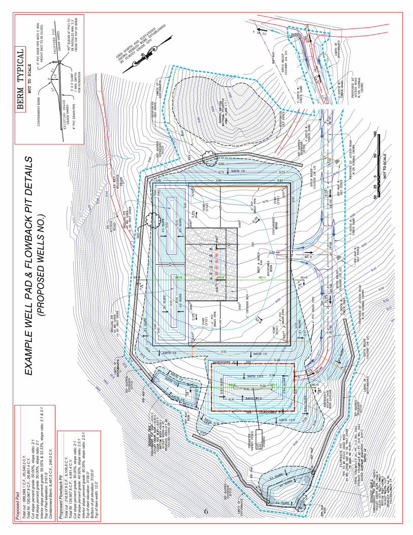
B. Construction and Reclamation Plan Preparation The Construction and Reclamation Plan is drawn up and submitted on Form WW-9 to the DEP, Office of Oil and
Gas, with a well work permit application. This plan must include drawings of the access road showing total road distance and slope and/or well location showing existing and proposed structures (including all pits) with approximate dimensions in accordance with the legend on said plan. Once the plan is completed the oil and gas inspector must be notified for field review and/or approval of the plan.

44

55
6
NO
T T
O S
CA
LE
NOT TO SCALE
7
SECTION IICONSTRUCTION
INDEX
A. Access Road Construction1. Access Roadway .........................................................................................................................................................82. Drainage Ditches .........................................................................................................................................................93. Cross Drain/Waterbars ..............................................................................................................................................104. Broad-Based Dip .......................................................................................................................................................105. Diversion Ditches – Temporary ................................................................................................................................106. Culverts .....................................................................................................................................................................117. Rock Check Dams .....................................................................................................................................................138 Sediment Control Barriers .........................................................................................................................................149. Erosion Controls ........................................................................................................................................................1610. Outlet Protection .......................................................................................................................................................1711. Stream Crossing – Temporary ..................................................................................................................................1712. Sediment Traps – Temporary ....................................................................................................................................18
B. Well Site Construction1. General ......................................................................................................................................................................232. Pit Construction .........................................................................................................................................................253. Construction of pits and impoundments with capacity greater than 5,000 barrels ...................................................26
C. Gathering Pipeline Construction .....................................................................................................................................27
FiguresII-1 Cross Drain/Waterbar ..................................................................................................................................................9II-2 Broad-Based Drainage Dip .......................................................................................................................................10II-3 Diversion Ditch-Temporary ......................................................................................................................................11II-4 Ditch Relief Culvert ..................................................................................................................................................12II-5 Rock Ditch Check Dams ...........................................................................................................................................13II-6 Sediment and Erosion Control for Access Roads and Driveways ............................................................................14II-7 Sediment Barrier Examples .......................................................................................................................................15II-8 Outlet Protection Examples .......................................................................................................................................17II-9 Stream Crossing – Temporary, with Culvert ...........................................................................................................18II-10 Brush Pile Sediment Barrier .....................................................................................................................................20II-11 Silt Fence Sediment Barrier ......................................................................................................................................20II-11a Filter Fabric Fence Reinforced by Stacked Straw Bales ...........................................................................................21II-11b Reinforced Silt Fence Sediment Barrier ...................................................................................................................21II-11c Super Silt Fence ........................................................................................................................................................22II-12 Well Site Cross Section View ...................................................................................................................................25II-13 Well Site Construction View ....................................................................................................................................25
TablesII-1 Allowable Side Slopes ..............................................................................................................................................28II-2 Permissible Velocities ...............................................................................................................................................28II-3 Spacing of Cross Drains ............................................................................................................................................28II-4 Spacing of Broad-Based Dips ...................................................................................................................................28II-5 Pipe Sizes for Culverts Across Road ........................................................................................................................29II-6 Spacing of Culverts ...................................................................................................................................................29II-7 Recommended Widths for Vegetation Strips Between Earth moving Activities and Streams .................................29II-10 Spacing of Pipeline Right-Of-Way Diversions .........................................................................................................29
8
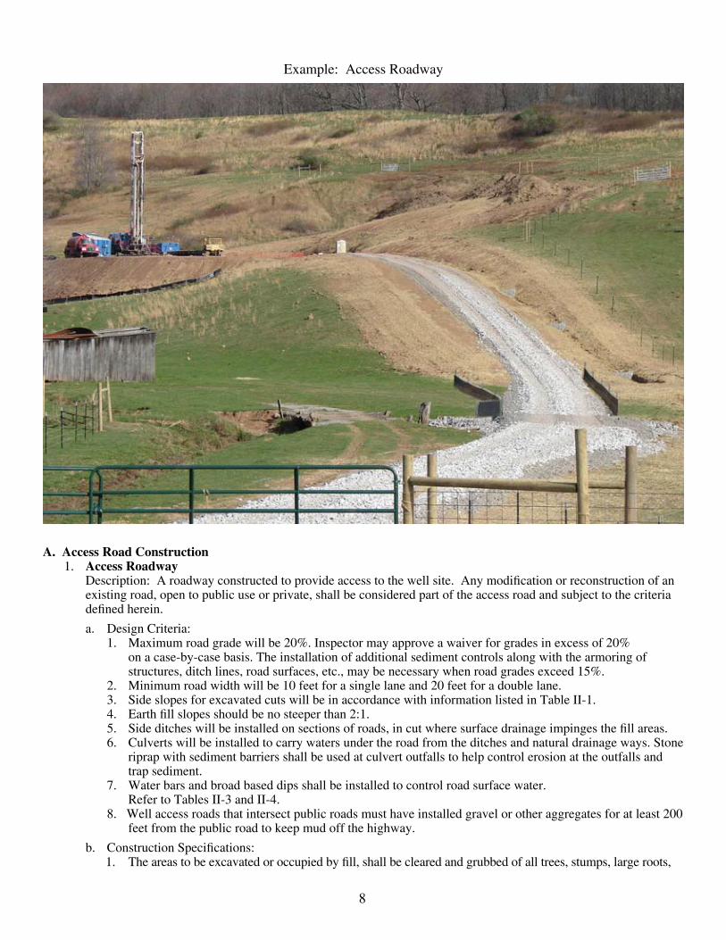
A. Access Road Construction1. Access Roadway Description: A roadway constructed to provide access to the well site. Any modification or reconstruction of an
existing road, open to public use or private, shall be considered part of the access road and subject to the criteria defined herein.
a. Design Criteria:1. Maximum road grade will be 20%. Inspector may approve a waiver for grades in excess of 20%
on a case-by-case basis. The installation of additional sediment controls along with the armoring of structures, ditch lines, road surfaces, etc., may be necessary when road grades exceed 15%.
2. Minimum road width will be 10 feet for a single lane and 20 feet for a double lane.3. Side slopes for excavated cuts will be in accordance with information listed in Table II-1.4. Earth fill slopes should be no steeper than 2:1.5. Side ditches will be installed on sections of roads, in cut where surface drainage impinges the fill areas.6. Culverts will be installed to carry waters under the road from the ditches and natural drainage ways. Stone
riprap with sediment barriers shall be used at culvert outfalls to help control erosion at the outfalls and trap sediment.
7. Water bars and broad based dips shall be installed to control road surface water. Refer to Tables II-3 and II-4.
8. Well access roads that intersect public roads must have installed gravel or other aggregates for at least 200 feet from the public road to keep mud off the highway.
b. Construction Specifications:1. The areas to be excavated or occupied by fill, shall be cleared and grubbed of all trees, stumps, large roots,
Example: Access Roadway

9
boulders, and debris. All such material will be disposed of by stacking, piling, windrowing, burning (in accordance with WV Forest Fire Laws), removal from site, or other methods approved by the Inspector.
2. Clearing of vegetation should be kept to the minimum necessary for construction plus the installation of sediment controls.
3. Road surface stabilization may be required in excessively wet or soft areas, by use of stone and/or stone and fiber matting.
4. When crossing pipelines or other underground utilities, adequate protection should be provided. For as-sistance in location underground utilities in WV call 1-800-245-4848 (Miss Utility of WV).
5. When leaving a County or State Road Right-of-Way, a “Road Approach Permit” is required by the WV Division of Highways. Refer to the DOH Manual for specifications.
2. Drainage Ditch Description: An open drainage ditch constructed to a specific size and grade, along the road, to collect and con-
vey surface water.a. Design Criteria:
1. Ditch side slopes will not be steeper than 2:1, when excavated in soil. Refer to Table II-1 for allowable side slopes in other types of material.
2. For allowable velocities, refer to Table II-2. Capacity of ditch shall be based on handling the expected acreage of drainage. Minimum depth shall be 1 foot.
3. Cross section of the ditch shall be V-shaped.4. All ditches should have erosion protection and/or stabilizing measures (see Figure II-6).5. Ditch stabilizing measures can be seeding and mulching, rock ditch check dams, and lining with stone or
fabric, etc., depending upon ditch grade and expected velocity. 6. Ditch outlets shall have erosion and sediment control structures.
FIGURE II-1: Cross Drain/Water bar
10
3. Cross Drain/Water Bar Description: An open ditch, constructed across the roadway, to carry off road surface water. They are not intend-
ed to replace culverts. See Figure II-1.
a. Design Criteria:1. Minimum depth – 8 inches2. Minimum width – 2 feet 3. Ditch will be angled approximately 30 degrees at a grade of ½ inch per foot of length.4. Velocity will not exceed the permissible velocity listed for the particular soil type. See Table II-2.5. Proper outlet protection will be provided to prevent erosion and control sedimentation from the ditch dis-
charge. Material for the outlet can be rock, logs, concrete, or metal with the appropriate sediment barrier.6. Stabilization: Cross drains may need to be lined with erosion resistant materials, such as rock riprap. Rock
used for riprap must be hard, angular and of a quality resistant to weathering and disintegration.7. Spacing: Refer to Table II-3.
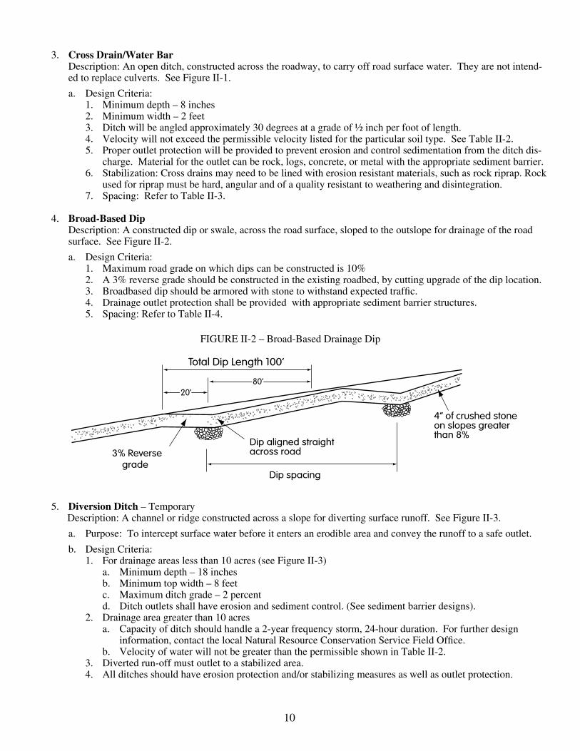
4. Broad-Based Dip Description: A constructed dip or swale, across the road surface, sloped to the outslope for drainage of the road
surface. See Figure II-2.
a. Design Criteria:1. Maximum road grade on which dips can be constructed is 10%2. A 3% reverse grade should be constructed in the existing roadbed, by cutting upgrade of the dip location.3. Broadbased dip should be armored with stone to withstand expected traffic.4. Drainage outlet protection shall be provided with appropriate sediment barrier structures.5. Spacing: Refer to Table II-4.
FIGURE II-2 – Broad-Based Drainage Dip
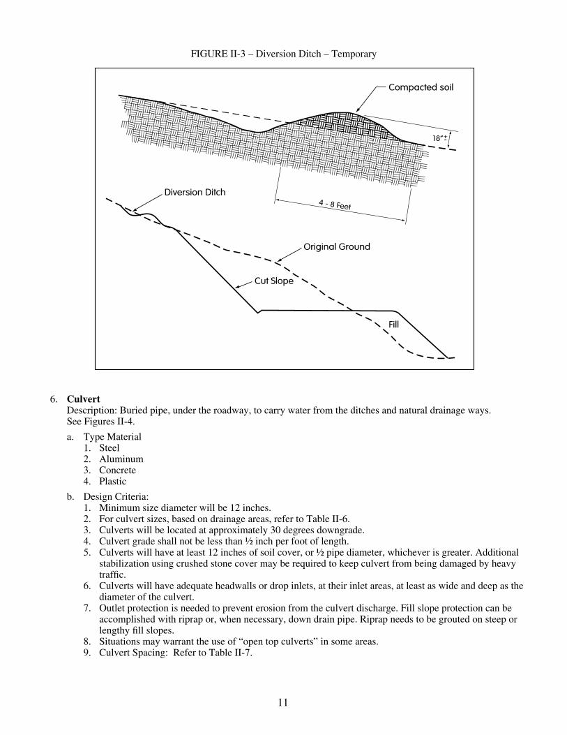
5. Diversion Ditch – Temporary Description: A channel or ridge constructed across a slope for diverting surface runoff. See Figure II-3.
a. Purpose: To intercept surface water before it enters an erodible area and convey the runoff to a safe outlet.
b. Design Criteria:1. For drainage areas less than 10 acres (see Figure II-3) a. Minimum depth – 18 inches b. Minimum top width – 8 feet c. Maximum ditch grade – 2 percent d. Ditch outlets shall have erosion and sediment control. (See sediment barrier designs).2. Drainage area greater than 10 acres a. Capacity of ditch should handle a 2-year frequency storm, 24-hour duration. For further design information, contact the local Natural Resource Conservation Service Field Office. b. Velocity of water will not be greater than the permissible shown in Table II-2.3. Diverted run-off must outlet to a stabilized area.4. All ditches should have erosion protection and/or stabilizing measures as well as outlet protection.
11
FIGURE II-3 – Diversion Ditch – Temporary
6. Culvert Description: Buried pipe, under the roadway, to carry water from the ditches and natural drainage ways.
See Figures II-4.
a. Type Material 1. Steel 2. Aluminum 3. Concrete 4. Plastic
b. Design Criteria: 1. Minimum size diameter will be 12 inches. 2. For culvert sizes, based on drainage areas, refer to Table II-6. 3. Culverts will be located at approximately 30 degrees downgrade. 4. Culvert grade shall not be less than ½ inch per foot of length. 5. Culverts will have at least 12 inches of soil cover, or ½ pipe diameter, whichever is greater. Additional
stabilization using crushed stone cover may be required to keep culvert from being damaged by heavy traffic.
6. Culverts will have adequate headwalls or drop inlets, at their inlet areas, at least as wide and deep as the diameter of the culvert.
7. Outlet protection is needed to prevent erosion from the culvert discharge. Fill slope protection can be accomplished with riprap or, when necessary, down drain pipe. Riprap needs to be grouted on steep or lengthy fill slopes.
8. Situations may warrant the use of “open top culverts” in some areas. 9. Culvert Spacing: Refer to Table II-7.

12
FIGURE II-4 – Ditch Relief Culvert
c. Construction Specifications:1. Culverts will be installed to a specified line and grade.2. Ditch will be excavated to a depth and grade to ensure proper cover for the culvert.3. Ditch bottom will have a firm foundation for the culvert. Gravel may be used to stabilize the ditch
bottom.4. The culvert will be backfilled with material free of large rocks, which may cause damage to it.5. Stone may be needed for further surface stabilization.6. Recommended installation is with a backhoe rather than a dozer.7. Culverts will have outlet protection (i.e. field rock or riprap, and sediment barriers) as well as natural filter
strip areas.8. Culverts with outlets onto lengthy fill slopes may require slope drains with outlet protection depending on
the steepness of the outslope.9. Riprap used as outlet protection must be hard, angular and of a quality resistant to weathering and disinte-
gration. Riprap should be grouted on steep or lengthy fill slopes with a minimum thickness two times the maximum stone diameter, but not less than six inches.
13
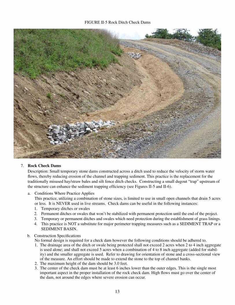
FIGURE II-5 Rock Ditch Check Dams
7. Rock Check Dams Description: Small temporary stone dams constructed across a ditch used to reduce the velocity of storm water
flows, thereby reducing erosion of the channel and trapping sediment. This practice is the replacement for the traditionally misused hay/straw bales and silt fence ditch checks. Constructing a small dugout “trap” upstream of the structure can enhance the sediment trapping efficiency (see Figures II-5 and II-6).
a. Conditions Where Practice Applies This practice, utilizing a combination of stone sizes, is limited to use in small open channels that drain 5 acres
or less. It is NEVER used in live streams. Check dams can be useful in the following instances: 1. Temporary ditches or swales 2. Permanent ditches or swales that won’t be stabilized with permanent protection until the end of the project. 3. Temporary or permanent ditches and swales which need protection during the establishment of grass linings. 4. This practice is NOT a substitute for major perimeter trapping measures such as a SEDIMENT TRAP or a SEDIMENT BASIN.
b. Construction Specifications No formal design is required for a check dam however the following conditions should be adhered to.
1. The drainage area of the ditch or swale being protected shall not exceed 2 acres when 2 to 4 inch aggregate is used alone; and shall not exceed 5 acres when a combination of 4 to 8 inch aggregate (added for stabil-ity) and the smaller aggregate is used. Refer to drawing for orientation of stone and a cross-sectional view of the measure. An effort should be made to extend the stone to the top of channel banks.
2. The maximum height of the dam should be 3.0 feet.3. The center of the check dam must be at least 6 inches lower than the outer edges. This is the single most
important aspect in the proper installation of the rock check dam. High flows must go over the center of the dam, not around the edges where severe erosion can occur.

14
FIGURE II-6 – Sediment and Erosion Control for Access Roads
8. Sediment Control Barriers Description: A temporary restriction or barrier across a slope, at the toe of a slope, or at drainage outlets designed
to trap sediment from a disturbed area by retarding and filtering water runoff. See Figure II-7, 8, 10, 11, 11a, b and c.
a. Types of Barriers1. Vegetative Filter Strip2. Silt fences

15
3. Brush Barriers4. Temporary earth or rock barriers5. Sediment trap or basin6. Compost filter Socks7. Straw Bales
b. Construction Specifications:1. Vegetative filter strip: A natural vegetative strip, left undisturbed, between the disturbed construction
area and any surface water. The filter strip of vegetation acts as a buffer area to catch sediment before it enters the surface water. The width of the filter strip needed depends on the slope of the land and the type of vegetation on the filter strip. Refer to Table II-8. A vegetative filter strip cannot always be used as a stand alone sediment control, but should be used in conjunction with other sediment retainment structures, silt fences, filter socks, etc.
2. Silt fence: Silt fences should be placed on the contour. Fence posts shall not be spaced greater than 10 feet apart. If woven wire fence is used, it shall be fastened securely on the upstream side of the fence posts. Filter cloth, when used, shall be secured on the upstream side of the fence posts and anchored at the bottom. The filter cloth shall be embedded in the soil at least 4 inches and the soil compacted around it. Silt fences are not for concentrated flows. In areas where concentrated flows can be expected, use ar-mored diversions and sediment traps. In ditches or swales rock check dams should be used. See silt fences Figures II-11, 11a, b and c.
FIGURES II-7 Sediment Barrier Examples

16
3. Brush barriers: Brush barriers shall be a minimum of 3 feet in height and 5 feet in width at the base. Brush barriers are perimeter sediment control structures constructed of small tree branches, root mats, stone, or other debris left over from site clearing. They may be constructed as single pile units or wind-rowed, along the contour or at the base of a slope. The brush should be cut so it can be compacted somewhat tightly together. Sizes of brush barriers may vary considerably based upon the amount of ma-terial available. Brush barrier effectiveness can be greatly increased with the use of a fabric cover on the up-slope side of the brush barrier. The brush barrier can be very effective at stopping large debris, rocks, stumps, but may need backed up with a silt fence to trap sediment.
4. Earth or rock barriers: Earth or rock barriers should not be more than 2 feet in height and have side slopes of 3:1 or less.
5. Sediment trap basin: A sediment trap is a temporary ponding area formed by constructing an embank-ment or excavation at the outlet of ditches and other perimeter sediment controls that will trap the flow of sediment- laden runoff. Sediment traps are appropriate for drainage areas of five acres or less. A sedi-ment basin should be used for drainage areas of more than five acres.
6. Compost filter sock: A compost filter sock is a mesh tube filled with composted material that is placed perpendicular to sheet-flow runoff to control erosion and retain sediment from disturbed areas. A filter sock can be used as a perimeter control in the place of the traditional silt fence or straw bales. The smaller diameter filter socks can be used to slow ditch water drainage and for inlet protection.
7. Straw bales: Straw or hay bales have historically been used on construction sites for erosion and sedi-ment control and perimeter sediment control, but straw bales have limitations. Straw bales are not able to withstand high flows, have a limited lifespan, and care must be taken during placement and installation to avoid failure from undercutting, overtopping, and end-running. Another factor to consider is that straw bales and especially hay bales may introduce undesirable non-native plants to the area.
9. Erosion Control Description: Erosion is the gradual wearing away of soils by the action of water and wind. Protection of bare soils
from the wearing effects of water and wind, especially topsoil, decreases sediment loss.
Example: Hydroseeding

17
a. Types of Erosion Control 1. Preserving Existing Vegetation -- Vegetative Filter Strip pg. 15 2. Temporary Seeding -- pg. 36 3. Permanent Seeding -- pg. 37 4. Outlet Protection -- pg. 17 5. Rock Check Dams -- pg. 13 6. Right of Way Diversions -- pg. 10 7. Riprap -- pg. 17 8. Rolled Erosion Control Products -- pg. 16
10. Outlet Protection: All culvert outlets shall have some type of energy dissipating structure for erosion protection such as: boulders, tree stumps or rock riprap.
a. Boulders (large ungraded field stone or shot rock).b. Tree stumps larger than 6 inch diameter. c. Rock riprap consisting of fieldstone or rough un-hewn quarry stone; must be hard, angular and of a quality
resistant to weathering and disintegration. The minimum thickness shall be two times the maximum stone diameter, but not less than six inches.
FIGURE II-8 Outlet Protection
11. Stream Crossing – Temporary
Description: A temporary structural span installed across a flowing watercourse, for use of construction traffic, drilling equipment, etc., so as to provide a means to cross the stream without damaging the stream and to prevent sediment from entering the stream (see Figure II-12).
a. Types: 1. Culverts 2. Bridge 3. Stone base

18
FIGURE II-9: Stream Crossing – Temporary, with Culvert
12. Sediment Traps – Temporary Description: A trap constructed to collect water runoff, with adequate retention time to allow sediment to settle.
a. Design Criteria:1. Water containing sediment from any disturbed area is diverted to the trap.2. The sediment trap shall have adequate overflow pipes and/or spillways installed, with outlet protection.
b. Design Criteria:1. The structure shall be large enough to handle a 1-year frequency storm, 24 hour duration.2. Depth of cover over culverts shall be ½ the diameter of the culverts used or 12 inches, whichever is
greater.3. Multi-culverts should be installed with spaces between them, equal to ½ the pipe diameter.4. Low water crossings may be used, if protected when overflowing occurs. This can be accomplished by
using rock and concrete.5. Cross cribbing of the downstream side of culvert installations may be needed to aid in reducing structural
damage during high velocity water overflow periods.6. If culverts or bridges are not used and a stone base doesn’t exist, stone shall be installed, with the entrance
and exit being stoned for approximately 100 feet.7. Ditch line exit points at stream crossings must have sediment controls.
Stream crossing structures may require a “Stream Activity Permit” from the WV Office of Land and Streams (formally the Public Lands Corporation) of the West Virginia Division of Natural Resources (304) 558-3225 and Fax (304) 558-6048 and a permit from the Army Corps of Engineers.

19
Example: Sediment Trap
3. The area of drainage is used to calculate the sizing and construction of the sediment trap . The maximum acreage that a sediment trap is designed to handle is five acres. For areas larger than five acres more than one sediment trap should be used, or a sediment basin design could be needed.
4. The sediment trap should have a storage volume of 3600 cubic feet per acre of drainage area. Half of the volume must be in the form of a permanent pool or wet storage to provide a stable-settling medium. The remaining half must be in the form of a drawdown or dry storage, which provides extended settling time.
5. The embankment should not exceed 5 feet in height. The recommended minimum width at the top of the embankment should be equal to the height of the embankment.
6. The recommended inside embankment slope should be a 2:1 slope or flatter. The recommended outside embankment slope should be a 3:1 or flatter.
7. The sediment trap must have a stabilized outlet. If a stone outlet is used the crest of the stone outlet must be at least 1 foot below the top of the embankment. The stone for the outlet should be a combination of coarse aggregate and rock riprap separated from the earthen embankment by a geotextile.
20
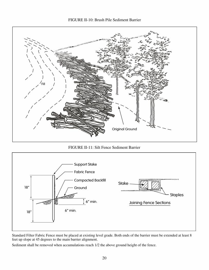
FIGURE II-11: Silt Fence Sediment Barrier
Standard Filter Fabric Fence must be placed at existing level grade. Both ends of the barrier must be extended at least 8 feet up slope at 45 degrees to the main barrier alignment.
Sediment shall be removed when accumulations reach 1/2 the above ground height of the fence.
FIGURE II-10: Brush Pile Sediment Barrier

21
FIGURE II-11b: Reinforced Silt Fence Sediment Barrier
Standard Filter Fabric Fence and Straw Bale Reinforced Filter Fabric Fence (30” high)
Standard Filter Fabric Fence must be placed at existing level grade. Both ends of the barrier must be extended at least 8 feet up slope at 45 degrees to the main barrier alignment.
Sediment shall be removed when accummulations reach 1/2 the above ground height of the fence.
FIGURE II-11a: Filter Fabric Fence Reinforced by Staked Straw Bales

22
FIGURE II-11c: Super Silt Fence Sediment Barrier
A super silt fence is a temporary barrier of geotextile fabric over chain link fence. It is used to intercept sediment-laden runoff from areas that are too large for regular silt fence. Super silt fence can be a replacement for sediment traps in cer-tain instances. Super silt fence can be used where the installation of a diversion and/or sediment trap would destroy sensi-tive areas, woods, wetlands, riparian zones, etc. This practice is very useful along streams and rivers. Slope length above the fence should not exceed 400 feet in steep terrain. In flatter terrain, the slope length can be extended with consultation with DEP. Super silt fence should be placed as close to the contour as possible. No section of silt fence should exceed a grade of 5 percent for more than a distance of 20 feet.
Chain link fence shall be fastened securely to the fence posts with wire ties or staples. Geotextile fabric shall be fastened securely to the chain link fence with ties spaced every 24 inches at the top and mid-sections.
Geotextile fabric shall be embedded a minimum of 12 inches into the ground.
When two sections of geotextile fabric adjoin each other, they shall be overlapped by 6 inches and folded.
Metal posts as specified by WV DOT can be replaced by pressure-treated 4” x 4” posts.
Super silt fence should be inspected at a minimum once every seven calendar days and within 24 hours after any storm event greater than 0.5 inches of rain per 24 hour period. Any required repairs shall be made immediately.
23
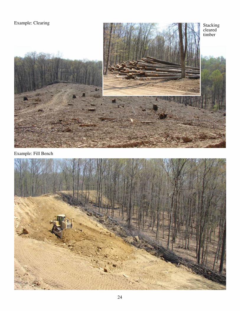
B. Well Site Construction1. General – Choose the site carefully to minimize the amount of area disturbed and size the site to accommodate
the equipment used.a. Clear any woody material, brush and trees, within the proposed site. Clearing of vegetation should be kept to
the minimum necessary for proper construction plus the installation of necessary sediment controls.b. Trees 6 inches or larger shall be cut and logs stacked. Smaller trees, brush, and stumps shall be cut and/or
grubbed and windrowed in appropriate areas for use as sediment barriers at water drainage outlets, windrowed below the well site, used for wildlife habitat, burned (as per WV Forest Fire Laws), removed from site, or disposed by other methods approved by DEP.
c. Topsoil shall be removed and stockpiled in agricultural areas. In woodland areas, tree stumps, large roots, large rocks, tree and leaf debris, and ground vegetation shall be removed prior to actual site construction.
d. Earthen fill slopes should be constructed with slopes no steeper than a ratio of two-to-one (2:1). No embank-ment shall be placed on frozen material. The fill material shall be clean mineral soil, free of roots, woody vegetation, stumps, sod, large rocks, or other objectionable material. The fill material shall exhibit adequate soil strength and moisture content to ensure that proper compaction will be achieved. Fill material will be placed in lifts or layers over the length of the fill. Lift thickness of soil shall be as thin as the suitable random excavated material will permit, typically from 6 to 12 inches. The size of rock lifts shall not exceed 36 inches. The rock shall not be greater in any dimension than thirty-six (36) inches.
2. Engineered Horizontal Well Sites (This applies to sites which disturb 3 or more acres of surface, excluding pipelines and roads) a. Fill material will be placed in compacted lifts or layers over the length of the fill. Each lift shall be compacted
by compaction equipment, sheep’s foot or pad roller, with compaction to visible non-movement of the em-bankment material. Compaction effort shall not exceed optimum moisture limits. Each lift shall be compacted to a standard proctor density of at least 95% before beginning the next lift.
b. Plan to divert surface water runoff around the site. Surface water diversion ditches shall be constructed above the disturbed area to intercept water. If the situation warrants, a diversion ditch may be constructed below the disturbed area to aid in sediment control (see Diversion Ditch Figure II-3).
c. In areas of steep terrain, a terraced bench shall be constructed at the base of the slope where fill is to be placed, creating a toe foundation to aid in holding the fill material. Additional terracing shall be constructed for each additional fifty (50) vertical feet of slope and shall be a minimum of ten (10) feet wide.
d. Drainage ditches should be constructed at the base of highwalls or as needed on location to aid in water con-trol on the construction site.
e. Sediment barriers shall be installed at drainage outlets and below the construction site. 1. Vegetative Filter Strips 2. Silt fences 3. Brush piles 4. Earthen or rock berms 5. Sediment traps 6. Compost Filter socks 7. Straw Balesf. In situations of extended time lapse between construction and reclamation, temporary seeding and mulching
of slopes will be needed to reduce erosion and stream sedimentation potential. Conditions where the tempo-rary seeding practice applies is where exposed soil surfaces are not to be worked or fine-graded for periods longer than 21 days.
g. Well sites need water runoff and spill protection. Measures such as berms with closable pipe slope drains directed to stabilized ditches should be considered.
h. Revegetation of areas of drill site and roadway not expected to be reworked, especially the cut and fill slopes, should begin immediately after construction. The least expensive and one of the best erosion and sediment controls is temporary seeding with mulch applied, or permanent seeding (see section IV Revegetation).
24
Example: Clearing Stacking cleared timber
Example: Fill Bench
25
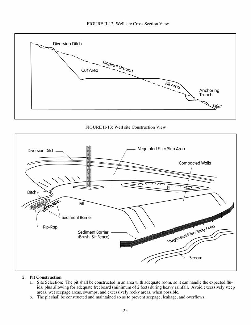
FIGURE II-13: Well site Construction View
FIGURE II-12: Well site Cross Section View
2. Pit Constructiona. Site Selection: The pit shall be constructed in an area with adequate room, so it can handle the expected flu-
ids, plus allowing for adequate freeboard (minimum of 2 feet) during heavy rainfall. Avoid excessively steep areas, wet seepage areas, swamps, and excessively rocky areas, when possible.
b. The pit shall be constructed and maintained so as to prevent seepage, leakage, and overflows.

26
c. Pits should be constructed below surface ground level, when possible. Any aboveground pit walls, as is the case with pits constructed in the lower slope areas of the well site, shall be compacted, with a side slope no steeper than a slope of 2:1. The fill material should contain the proper amount of moisture to ensure that com-paction will be achieved.
d. Areas under the proposed pit walls or embankments shall be cleared, grubbed and stripped of topsoil to re-move trees, vegetation, and other objectionable material. The fill material shall be clean mineral soil, free of roots, woody vegetation, stumps, sod, oversized stones, rocks, or other unwanted material.
e. Surface water must be diverted from the pit. The pit liner anchoring trench must not be used as a diversion ditch.f. For the earthen pit to be impervious, a synthetic liner will be needed. On a site specific basis other methods
may be approved. Various materials protecting synthetic liners may be necessary, such as: 1. Hay or straw bedding 2. Clay3. Fiber matting
g. Pits constructed on location, shall be constructed in solid ground, preferably on the cut or highwall side, not in the fill area. Adequate room shall be allowed between the base of any highwalls and the pit, for the construc-tion of a surface water diversion ditch.
h. Steel pits may be used as an alternative to earthen pits.
3. Construction of pits and impoundments with capacity greater than 5,000 barrels (35CSR 4.21)a. All pits and impoundments used in association with an oil and gas operation, whether permitted or not, shall
be constructed only in locations appropriate for the storage of water, including wastewater. b. All pits and pad impoundments shall be designed, constructed, located, maintained, and used in accordance
with Title 35CSR4.21 and in such a manner as to minimize adverse environmental impacts and to assure safety to the public.
c. Operators shall provide notice to the Office of Oil and Gas prior to commencing construction on any pit or impoundment with a capacity of greater than 5,000 barrels.
d. Such notice shall identify the location and dimensions of the pit or impoundment. The Office of Oil and Gas shall have the authority for inspection of these sites and the enforcement.
e. Impoundment fill slopes shall be no steeper than a slope of 2:1.
Example: Impoundment

27
C. Gathering Pipeline Construction* * (See 35CSR4.16.7, Requirements for Production and Gathering Pipelines ) This section addresses pipelines associated with oil and gas wells such as gathering lines, injection lines, and water
supply lines for enhanced recovery operations where the primary method of excavation is with a backhoe or trench excavator. 1. Lines shall be buried where practical and reasonable.
a. Where the line crosses agricultural land.b. Where an unburied line would prohibit use of a pre-existing private roadway or other means of access to a
part of or all of surface land.c. Where the line cannot more practically and reasonably be securely suspended to cross stream beds.d. Where the line crosses a public road, in which event it shall be buried and otherwise installed in accordance
with the rules of the WVDOH having jurisdiction over the road.e. Where the chief decides prior to installation that burial would be practical and reasonable.
2. All buried lines shall be installed with a minimum of eighteen (18) inches of cover, except where solid rock is encountered in which case the minimum cover shall be six (6) inches.
3. Whenever a buried line crosses a pre-existing public or private roadway, the location of the line shall be clearly marked at the point of crossing by an appropriate marker.
4. A suitable conductive wire shall be installed with plastic pipe to facilitate locating it with an electronic pipe loca-tor; provided, that any other suitable material or means for accomplishing this purpose may be employed.

28
Table II-1 Allowable Side Slopes
Material Slope Horizontal-Vertical
Soil (clay – silt) 2:1
Sand (clean) 2:1
Shale 1:1
Rock ½ :1
Table II-2 Permissible Velocities
Soil Texture Maximum Velocity Ft./sec.
Stand and sandy loam (noncolloidal) 2.5
Silt loam (also high lime clay) 3.0
Sandy clay loam 3.5
Clay loam 4.0
Stiffclay,finegravel,gradedloamtogravel 5.0
Gradedsilttocobbles(colloidal) 5.5
Shale,hardpanandcoarsegravel 6.0
Table II-3 Spacing of Cross Drains
Road Grade (%) Distance Between Drains (Ft)
1 400
2 250
5 135
10 80
15 60
20 45
Table II-4 Spacing of Broad-Based Dips
Road Grade (%) Distance Between Drains (Ft)
2 300
3 235
4 200
5 180
6 165
7 155
8 150
9 145
10 140
29
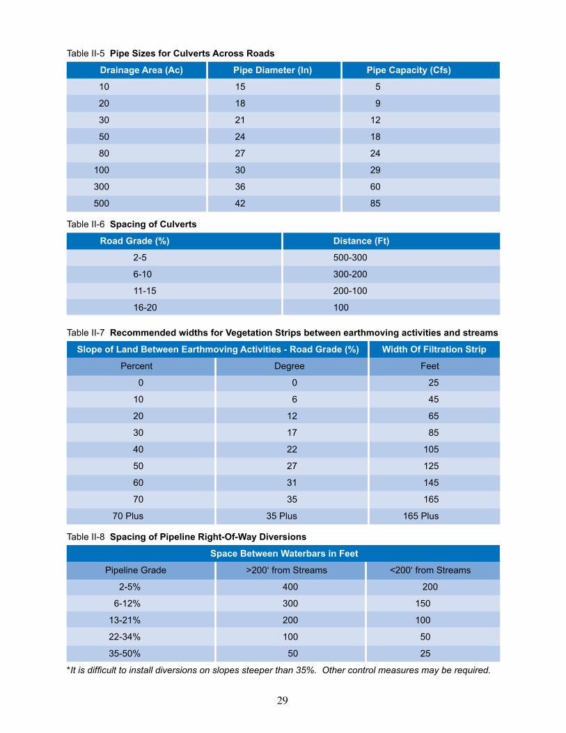
Table II-5 Pipe Sizes for Culverts Across Roads
Drainage Area (Ac) Pipe Diameter (In) Pipe Capacity (Cfs)
10 15 5
20 18 9
30 21 12
50 24 18
80 27 24
100 30 29
300 36 60
500 42 85
TableII-6Spacing of Culverts
Road Grade (%) Distance (Ft)
2-5 500-300
6-10 300-200
11-15 200-100
16-20 100
Table II-7 Recommended widths for Vegetation Strips between earthmoving activities and streams
Slope of Land Between Earthmoving Activities - Road Grade (%) Width Of Filtration Strip
Percent Degree Feet
0 0 25
10 6 45
20 12 65
30 17 85
40 22 105
50 27 125
60 31 145
70 35 165
70Plus 35Plus 165Plus
Table II-8 Spacing of Pipeline Right-Of-Way Diversions
Space Between Waterbars in Feet
PipelineGrade >200‘fromStreams <200‘fromStreams
2-5% 400 200
6-12% 300 150
13-21% 200 100
22-34% 100 50
35-50% 50 25
*It is difficult to install diversions on slopes steeper than 35%. Other control measures may be required.

30
SECTION IIIRECLAMATION
All disturbed areas used in connection with the oil and gas operation shall be reclaimed, as per state requirements. Recla-mation shall include activities such as backfilling, installing permanent drainage structures, and revegetation.
INDEX
A. Well Site Reclamation .................................................................................................................................................... 31B. Access Road Reclamation .............................................................................................................................................. 31C. General Notes ................................................................................................................................................................. 32D. Tank Dike Construction .................................................................................................................................................. 32E. Seismic Activity .............................................................................................................................................................. 33
FiguresFigure III-1: Bulldozer Tracking Procedure ......................................................................................................................... 31Figure III-2: Dike Design Data, 100 Bbl. Tank .................................................................................................................... 32
TableTable III-1: Dike Design Data .............................................................................................................................................. 33
Example: Reclaimed Shallow Well Site

31
A. Well site Reclamation 1. Drilling Pit Reclamation
a. All fluid must be removed from the pit prior to backfilling and disposed of in an approved manner or recycled. b. Pit backfilling: Drill cuttings associated with wells permitted under WV Code 22-6 may be buried on site and
must be covered with soil (minimum of 3 feet of coverage), and recontoured; drill cuttings and associated pit material must remain under this cover.
c. Drill cuttings, drilling mud and liner, for wells permitted under WV Code 22-6A and 35CSR-8, must be removed from site and disposed of at an approved solid waste facility or if the surface owner consents the drill-ing cuttings and associated drilling mud may be managed on site in a manner approved by the secretary.
d. All pits and impoundments that are not required or allowed by state or federal law or rule or agreement be-tween the operator and the surface owner must be backfilled.
e. The operator shall grade or terrace and plant, seed or sod the area disturbed that is not required in production of the well in accordance with the erosion and sediment control plan.
f. Install all permanent water drainage and diversion ditches. In areas of long slopes, it may be desirable to install angled diversion ditches to aid in controlling water runoff and erosion.
g. Stockpiled topsoil should be re-spread over disturbed area. Topsoil should not be added to slopes steeper than 2:1 unless good bonding to the sub-soil can be achieved.
h. Prior to seeding soil should be loosened by disking, bulldozer tracking, etc. Note that bulldozer tracking can compact wet clay soils and restrict establishment of vegetation.
i. Maintaining sediment barriers is critical until vegetation is reestablished. Temporary sediment control devices such as silt fencing shall be removed along with sediment after at least a 70% vegetative cover is established.
B. Access Road Reclamation 1. Road surfaces shall be stabilized and/or reseeded. 2. Permanent side ditches will be installed where needed and where the site will allow. 3. Permanent culverts, cross drains, and broad-based dips shall be installed based on criteria in
Construction (Section II).
FIGURE III-1: Bulldozer Tracking Procedure

32
4. Side slopes of excavated cuts and outslopes shall be maintained, where the site allows, as per criteria in Section II.
5. Sediment barriers shall be maintained until vegetation is reestablished. Temporary sediment control devices such as ditch line checks and silt fencing shall be removed along with collected sediment after at least a 70% vegetation cover is established.
C. General Notes Regarding Reclamation 1. Pipelines: any disturbed areas created by pipeline installation shall be reclaimed in accordance with state
requirements. 2. Tank Batteries, power lines: Any disturbed areas created by the installation of tank batteries or
power lines, even if out of the immediate construction site shall be reclaimed in accordance with state requirements, as these operations are used in connection with the “permitted” operation.
3. Well Maintenance: disturbed areas created due to well maintenance, shall be reclaimed, mulched and seeded, to reduce erosion and sedimentation.
4. API Numbers: API Identification Numbers shall be displayed at the well, in accordance with state requirements.
D. Tank Dike Construction Tank dike construction or secondary containment structures, shall be in accordance with federal and state S.P.C.C.
Regulations (see Figure III-2). 1. Secondary containment area shall be large enough to contain the contents of the single largest tank, per
battery, plus 10%. 2. Containment area shall be impervious and be compatible with the potential spill material. 3. Dike walls can be constructed with earthen material, concrete, or other impervious material. 4. Earthen dike walls should be compacted and sloped. Height of dike walls need added dimensions for allowances
in compaction, weathering and erosion considerations. Wall construction is recommended with a height of 3 feet and a top width of 2 feet to allow for settlement over time and adequate free board. Material used shall be free of roots, rocks, and debris.
FIGURE III-2: Dike Design Data, 100 Bbl. Tank
33
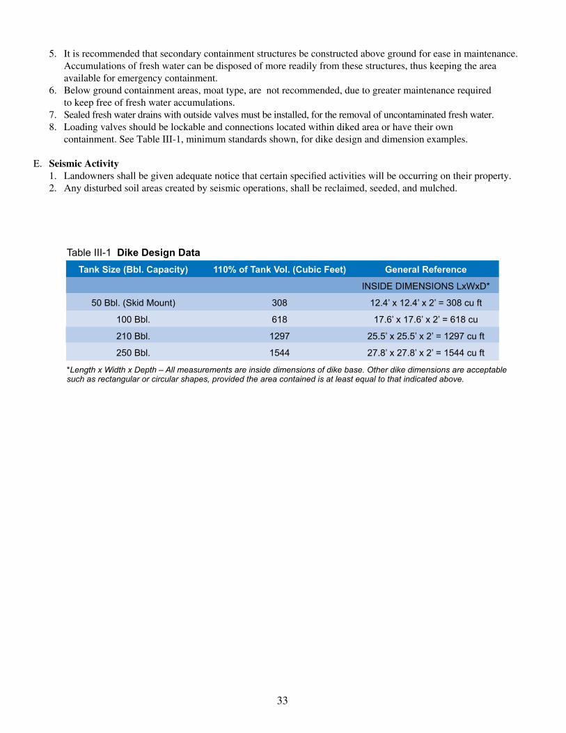
5. It is recommended that secondary containment structures be constructed above ground for ease in maintenance. Accumulations of fresh water can be disposed of more readily from these structures, thus keeping the area available for emergency containment.
6. Below ground containment areas, moat type, are not recommended, due to greater maintenance required to keep free of fresh water accumulations.
7. Sealed fresh water drains with outside valves must be installed, for the removal of uncontaminated fresh water. 8. Loading valves should be lockable and connections located within diked area or have their own
containment. See Table III-1, minimum standards shown, for dike design and dimension examples.
E. Seismic Activity 1. Landowners shall be given adequate notice that certain specified activities will be occurring on their property. 2. Any disturbed soil areas created by seismic operations, shall be reclaimed, seeded, and mulched.
Table III-1 Dike Design Data Tank Size (Bbl. Capacity) 110% of Tank Vol. (Cubic Feet) General Reference
INSIDEDIMENSIONSLxWxD*
50Bbl.(SkidMount) 308 12.4’x12.4’x2’=308cuft
100Bbl. 618 17.6’x17.6’x2’=618cu
210Bbl. 1297 25.5’x25.5’x2’=1297cuft
250Bbl. 1544 27.8’x27.8’x2’=1544cuft
*Length x Width x Depth – All measurements are inside dimensions of dike base. Other dike dimensions are acceptable such as rectangular or circular shapes, provided the area contained is at least equal to that indicated above.

34
SECTION IVREVEGETATION
INDEX
A. General 1. Objectives ................................................................................................................................................................. 36 2. Acreage Calculations ................................................................................................................................................ 36
B. Site Preparation 1. Water Control ............................................................................................................................................................ 36 2. Seedbed Preparation .................................................................................................................................................. 36
C. Seeding 1. Temporary Seeding ................................................................................................................................................... 36 a. General ................................................................................................................................................................ 36 b. Seed Mixtures ..................................................................................................................................................... 36
c. Seed Application ................................................................................................................................................. 36 2. Permanent Seeding a. General ................................................................................................................................................................ 37 b. Lime and Fertilizer .............................................................................................................................................. 38 (1) Lime .............................................................................................................................................................. 38 (2) Fertilizer ........................................................................................................................................................ 38 c. Permanent Seed Mixtures ................................................................................................................................... 38 d. Seeding for Wildlife Habitat ............................................................................................................................... 38
D. Mulching 1. General organic mulches ........................................................................................................................................... 38 2. Chemical mulches, soil binders and tackifiers .......................................................................................................... 41 3. Specifications ............................................................................................................................................................ 41 4. Anchoring ................................................................................................................................................................. 41 a. Mechanical Anchoring ........................................................................................................................................ 41 b. Mulch Netting ..................................................................................................................................................... 41
E. Fencing ....................................................................................................................................................................... 41
TablesIV-1 Recommended seeding dates for permanent and temporary cover unless otherwise specified. .............................. 37IV-2 Acceptable fertilization recommendation in absence of a soil test .......................................................................... 37IV-3 Temporary cover suitable for establishment in West Virginia ................................................................................ 37 IV-4a Permanent seeding mixtures suitable for establishment in WV .............................................................................. 39IV-4b Permanent mixtures in this table are more farm-friendly ........................................................................................ 40IV-5 Lime and Fertilizer Application Table ..................................................................................................................... 40IV-6 Mulch Materials Rates and Uses ............................................................................................................................. 40

35
A. General 1. Objectives
This section provides planning and establishment of temporary and permanent vegetative cover on all disturbed ar-eas. The objective is to provide sufficient vegetation to control erosion and sedimentation on and off the site. A veg-etative cover of 70% or greater would generally meet this requirement. Considerations for the improvement of water quality and wildlife habitat are incorporated into this section. With prior and documented approval, these standards may be adjusted and modified to meet individual site requirements.
2. Acreage Calculation Application rates listed in this section are on a “per acre” basis. To calculate acreage, the planner must measure
the average length and width (in feet) of each area to be treated. Acreage is determined by multiplying the length by the width, then dividing the total by 43,560. Example: 430 feet long x 310 feet wide=133,300 sq. ft. Then: 133,300 divided by 43,560 = 3.06 acres.
B. Site Preparation1. Water Control Install needed surface water control measures, diversion ditches, water bars, sediment controls (see Section II,
Construction, for guidance).2. Seedbed Preparation The seedbed must be loose at the time of seeding. Applications of seed on hard ground will result in a poor stand
of vegetation. The soil surface must be loosened (minimum of 3 inches) by disking on the contour, or by bulldoz-er tracking up and down the slope. Backblading is acceptable on gentle slopes such as the bench or road bed. If seedbed preparation is not feasible, 50% more seed shall be added to the recommended rates shown in Tables 3-4. When hydroseeding, seedbed preparation may not be necessary if adequate site preparation was performed.
Apply all nutrient requirements immediately prior to seeding. Soil fertility and pH level should be tested and ad-justed according to seed species planted. Where sampling is impractical or not feasible, an all-inclusive fertilizer recommendation may be used as shown in Table 1.
Apply lime to bring soil pH to a range suitable (pH 6.0) for the planned species. In absence of a soils test, 3 tons/acre of lime may be applied (150 lbs./1000 sq. ft.). Incorporate the appropriate amount of lime and/or fertilizer in the slurry mix when hydroseeding.
C. Seeding 1. Temporary Seeding
a. General conditions where practice applies. Where exposed soil surfaces are not to be fine-graded or worked for periods longer than 21 days. Temporary
vegetative cover with sediment controls must be established where runoff will go directly into a stream. Im-mediately upon construction of the site (site includes road and location), vegetation must be established on road bank and location slopes. A permanent vegetative cover shall be applied to areas that will be left un-worked for a period of more than 6 months.
b. Seed Mixtures and planting dates Refer to Tables 2-4 for recommended dates to establish vegetative cover and the approved lists of temporary
and permanent plant species, and planting rates. Table 3 gives recommended types of temporary vegetation, rates of application, and optimum seeding dates. In situations where another cover is desired contact the local soil conservation district for seeding recommendations.
c. Seed Application Apply seed by broadcasting, drilling, or by hydroseeding according to the rates indicated in Table IV-3.
Perform all planting operations at right angles to the slope. Necessary site preparation, roughening of the soil surface, should be done just prior to seeding. Seedbed preparation may not be required on newly disturbed areas.
36
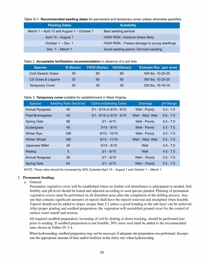
Table IV-1 Recommended seeding datesforpermanentandtemporarycoverunlessotherwisespecified.
Seed Planting Dates Suitability
March1–April15andAugust1–October1 Bestseedingperiods
April15–August1 HIGHRISK-moisturestresslikely
October1–Dec.1 HIGHRISK-Freezedamagetoyoungseedlings
Dec.1–March1 Goodseedingperiod.Dormantseeding.
2. Permanent Seeding:a. General Permanent vegetative cover will be established where no further soil disturbance is anticipated or needed. Soil
fertility and pH level should be tested and adjusted according to seed species planted. Planting of permanent vegetative covers must be performed on all disturbed areas after the completion of the drilling process. Any site that contains significant amounts of topsoil shall have the topsoil removed and stockpiled when feasible. Topsoil should not be added to slopes steeper than 2:1 unless a good bonding to the sub-layer can be achieved. After proper grading and seedbed preparation, the vegetation will reestablish ground cover for the control of surface water runoff and erosion.
All required seedbed preparation, loosening of soil by disking or dozer tracking, should be performed just prior to seeding. If seedbed preparation is not feasible, 50% more seed shall be added to the recommended rates shown in Tables IV 3-4.
When hydroseeding, seedbed preparation may not be necessary if adequate site preparation was performed. Incorpo-rate the appropriate amount of lime and/or fertilizer in the slurry mix when hydroseeding.
Table 2. Acceptable fertilization recommendation in absence of a soil test.
Species N (lbs/ac) P2O5 (lbs/ac) K2O(lbs/ac) Example Rec. (per acre)
CoolSeasonGrass 40 80 80 400lbs.10-20-20
CSGrass&Legume 30 60 60 300lbs.10-20-20
TemporaryCover 40 40 40 200lbs.19-19-19
Table 3. Temporary cover suitableforestablishmentinWestVirginia.
Species SeedingRate(lbs/acre) OptimumSeedingDates Drainage pHRange
AnnualRyegrass 40 3/1-6/15or8/15-9/15 Well-Poorly 5.5-7.5
FieldBromegrass 40 3/1-6/15or8/15-9/15 Well–Mod.Well 6.0-7.0
SpringOats 96 3/1-6/15 Well-Poorly 5.5-7.0
Sudangrass 40 5/15-8/15 Well-Poorly 5.5-7.5
WinterRye 168 8/15-10/15 Well-Poorly 5.5-7.5
WinterWheat 180 8/15-11/15 Well–Mod.Well 5.5-7.0
JapaneseMillet 30 6/15-8/15 Well 4.5-7.0
Redtop 5 3/1-6/15 Well 4.0-7.5
AnnualRyegrass 26 3/1-6/15 Well–Poorly 5.5-7.5
SpringOats 64 3/1-6/15 Well–Poorly 5.5-7.5
NOTE: These rates should be increased by 50% if planted April 15 – August 1 and October 1 – March 1.

37
When hydroseeding, first mix the lime, fertilizer, and hydro-mulch in the recommended amount of water. Mix the seed and inoculant together within one hour prior to planting, and add to the slurry just before seeding. Ap-ply the slurry uniformly over the prepared site. Assure that agitation is continuous throughout the seeding opera-tion and that the mix is applied within one hour of initial mixing.
b. Lime and Fertilizer 1. Lime shall be applied to all permanent seedings. The pH of the soil is to be determined and lime applied
accordingly. Once the pH is known, select the amount of lime to be applied from Table IV-5. 2. Fertilizer shall be applied in all permanent seedings. Apply the equivalent of 500 lbs. minimum
10-20-20 fertilizer per acre or use the amount of fertilizer and lime recommended by a certified soil test. 3. Application: For best results and maximum benefits the lime and fertilizer are to be applied at the
time of seedbed preparation. c. Permanent Seed Mixtures Planners should take into consideration the species makeup of the existing pasture and the landowner’s future
pasture management plans when recommending seed mixtures. Selection: From Tables IV 4a and b. Permanent seeding mixtures suitable for establishment in West Virginia. Notes:
1. All legumes must be planted with the proper inoculant prior to seeding. 2. ‘Lathco’ Flatpea is potentially poisonous to some livestock. 3. Only endophyte free varieties of Tall Fescue should be used. Tall Fescue and Crownvetch are also
a very invasive species non-native to WV. 4. For unprepared seedbeds or seeding outside the optimum timeframes, add 50% more seed to the specified
rate. Mixtures in table 4b are more wildlife- and farm-friendly; those listed in bold are suitable for use in shaded woodland settings. Mixtures in italics are suitable for use in filter strips.
d. Seeding for Wildlife Habitat Consider the use of native plants or locally adapted plants when selecting cover types and species for wild-
life habitat. Wildlife friendly species or mixes that have multiple values should be considered. See wildlife friendly species/mixtures in Table IV- 4b. Consider selecting no or low maintenance long-lived plants adapt-able to sites which may be difficult to maintain with equipment.
D. Mulching 1. General Organic Mulches
The application of straw, hay or other suitable materials to the soil surface to prevent erosion. Straw made from wheat or oats is the preferred mulch, the use of hay is permissible, but not encouraged due to the risk of spreading invasive species. Mulch must be applied to all temporary and permanent seeding on all disturbed areas. Depend-ing on site conditions, in critical areas such as waterways, or steep slopes, additional or substitute soil protective measures may be used if deemed necessary. Examples include jute mesh, and soil stabilization blankets or ero-sion control matting.
Areas that have been temporarily or permanently seeded should be mulched immediately following seeding. Mulches conserve desirable soil properties, reduce soil moisture loss, prevent crusting and sealing of the soil surface and provide a suitable microclimate for seed germination.
Areas that cannot be seeded because of the season should be mulched to provide some protection to the soil surface. An organic mulch, straw or hay, should be used and the area then seeded as soon as weather or seasonal conditions permit. Do not use fiber mulch (cellulose-hydroseed) alone for this practice; at normal application rates it will not give the soil protection of other types of mulch.
Wood cellulose fiber mulch, is used in hydroseeding operations and applied as part of the slurry. It creates the best seed-soil contact when applied over top of (as a separate operation) newly seeded areas. Fiber mulch does not alone provide sufficient protection on highly erodible soils, or during less than favorable growing conditions. Fiber mulch should not be used alone during the dry summer months or when used for late fall mulch cover. Use straw mulch during these periods, and fiber mulch may be used to tack (anchor) the straw mulch. Fiber mulch is well suited for steep slopes, critical areas, and areas susceptible to wind.

38
Table 4a. Permanent seeding mixturessuitableforestablishmentinWV.
Species/Mixture SeedingRate(lbs/acre) SoilDrainagePreference pHRange
Crownvetch/ 10-15 Well-Mod.Well 5.0-7.5TallFescue 30
Crownvetch/ 10-15 Well-Mod.Well 5.0-7.5PerennialRyegrass 20
Flatpea or Perennial Pea/ 20 Well-Mod.Well 4.0-8.0Tall Fescue 15
LadinoClover/ 30SereciaLespedeza/ 25 Well-Mod.Well 4.5-7.5TallFescue 2
Tall Fescue/ 40Ladino Clover/ 3 Well - Mod. Well 5.0 - 7.5Redtop 3
Crownvetch/ 10TallFescue/ 20 Well-Mod.Well 5.0-7.5Redtop 3
TallFescue/ 40BirdsfootTrefoil/ 10 Well-Mod.Well 5.0-7.5Redtop 3
SericeaLespedeza/ 25TallFescue/ 30 Well-Mod.Well 4.5-7.5Redtop 3
Redtop/ 30TallFescue/ 3 Well-Mod.Well 5.0-7.5CreepingRed 50
Tall Fescue 50 Well - Poorly 4.5 - 7.5
Perennial Ryegrass/ 10Tall Fescue/ 15 Well - Poorly 5.0 - 8.0Lathco Flatpea * 20
Tables IV 1-4 taken from Natural Resources Conservation Service Manual Critical Area Planting

39
Mixtures listed in bold are suitable for use in shaded woodland settings; those in italics are suitable for use in filter strips.* ‘Lathco’ Flatpea is potentially poisonous to some livestock. All legumes should be planted with proper inoculants prior to seeding.For unprepared seedbeds or seeding outside the optimum timeframes, add 50% more seed to the specified rate.
Table 4b. Mixtures in the table below are more wildlife and farm friendly.
Species/Mixture SeedingRate(lbs/acre) SoilDrainagePreference pHRange
KYBluegrass/ 20Redtop/ 3 Well–Mod.Well 5.5-7.5LadinoCloverorBirdsfootTrefoil 2/10
Timothy/ 5Alfalfa 12 Well–Mod.Well 6.5-8.0
Timothy/ 5BirdsfootTrefoil 8 Well-Poorly 5.5-7.58
Orchardgrass/ 10Ladino Clover/ 2 Well - Mod. Well 5.5 - 7.5Redtop 3
Orchardgrass/ 10Ladino Clover 2 Well - Mod. Well 5.5 - 7.5
Orchardgrass/ 20Perennial Ryegrass 10 Well - Mod. Well 5.5 - 7.5
Creeping Red Fescue/ 30Perennial Ryegra 10 Well - Mod. Well 5.5 - 7.5
OrchardgrassorKentuckyBluegrass 20 Well-Mod.Well 6.0-7.5
BirdsfootTrefoil/ 10Redtop/ 5 Well-Mod.Well 5.5-7.5Orchardgrass 20
Lathco Flat Pea/ 30Perennial Ryegrass 20 Well - Mod. Well 5.5 - 7.5
LathcoFlatPea/ 30Orchardgrass 20 Well-Mod.Well 5.5-7.5
Table IV-5 Lime and Fertilizer Application Table
pH of Soil Lime in Tons Per Acre Fertilizer, Lbs., per Acre 10-20-20- or Equivalent
Above6.0 2 500 5.0to6.0 3 500 Below5.0 4 500
The pH can be determined with a portable pH testing kit or by sending the soil samples to a soil testing laboratory. When 4 tons of lime per acre are applied it must be incorporated into the soil by disking, backblading or tracking up and down the slope.
TableIV-6Mulch Materials Rates and Uses
Material Minimum Rates Per Acre Coverage Remarks
HayorStraw 2to3Tons Cover75%to SubjecttoWindblowing 100to150Bales 90%ofSurface orwashingunlesstieddown WoodFiber1000to1500lbs Coverall ForHydroseeding PulpFiber DisturbedAreas Wood-Cellulose RecirculatedPaper

40
2. Chemical Mulches, Soil Binders and Tackifiers A wide range of synthetic, spray-on materials is marketed to stabilize and protect the soil surface. These are
mixed with water and sprayed over the mulch and to the soil. They may be used alone in some cases as temporary stabilizers, or in conjunction with fiber mulch, straw or hay.
When used alone most chemical mulches do not have the capability to insulate the soil or retain soil moisture that organic mulches have.
3. Specifications: From Table IV-6 select the type of mulch and rate of application that will best suit the conditions at the site. 4. Anchoring Depending on the field situation, mulch may not stay in place because of wind action or rapid water runoff. In
such cases, mulch is to be anchored mechanically or with mulch netting. a. Mechanical Anchoring Apply mulch and pull a mulch anchoring tool over the mulch. When a disk is used, set the disk
straight and pull across the slope. Mulch material should be tucked into the soil about three inches. b. Mulch Netting Follow manufacturer’s recommendations when positioning and stapling the mulch netting in the soil.
E. Fencing Livestock shall be controlled or excluded as necessary to allow for establishment and maintenance of the desired veg-
etative cover. Where livestock are present, the operator should consult with the affected landowner to coordinate the fence type and layout.
Also, permanent fencing may need installed as a protective measure around well site fixtures, sensitive areas or areas prone to recurring disturbance and erosion (e.g. slips).
Example: livestock fencing
41
SECTION VMAINTENANCE
A. Long Term Maintenance 1. General All revegetated access roads and well sites are to be maintained throughout the life of the well. Culverts, road
ditches, broad-based dips, and diversion ditches must be maintained in proper working order. Whenever the soil is disturbed on any well or road by well-related activity, it will be revegetated according to this manual.
B. Description of Grasses and Legumes for use in Revegetation 1. Temporary Seeding – See Table IV-3 Temporary Cover
a. Oats (Avena Sativa): A cool season annual grass primarily grown for animal feed and human con- sumption, but also used for soil stabilization. Oats are usually seeded in early spring.
b. Annual Ryegrass (Lolium Multiflorum): An annual bunch-grass that grows from one to two feet tall. Rye grasses cross-pollinate, so “common ryegrass” may be a mixture of annual and perennial species. Annual Ryegrass is adaptable throughout West Virginia. It grows best on dark, rich soils in mild climates. A firm, mellow surface over compact subsoil gives good results. It does not withstand dry, hot weather or severe winters. It will tolerate wet soils with good surface drainage. Annual Ryegrass germinates rapidly, which makes it particularly suited to disturbed-area stabilization and temporary seeding. However, it should not be used where volunteers will cause problems later.
2. Permanent Seeding – Perennial Grasses and Legumes-See Table IV-4 Permanent Covera. Kentucky Bluegrass (Poa Pretense): A long-lived, cool-season perennial which forms a dense sod; it may
be used to stabilize waterways, slopes, cuts and fills, as well as lawns, athletic fields, golf courses and play-grounds. It is well adapted to well-drained, fertile soils and the climate throughout West Virginia. The op-timum soil pH ranges from 6.0 to 7.0. Bluegrass is essentially dormant during dry or hot weather, but it will survive severe drought. It requires a firm, weed-free seedbed, and adequate fertilizer (liberal phosphorous) and lime are important. The minimum mowing height is 1 ½ inches; critical erosion areas may be mowed only once a year. Several varieties of bluegrass may be used together to ensure good stand survival.
b. Tall Fescue (Festuca arundinacea): A cool-season perennial that is commonly used for pastures, hay, recre-ational areas and low maintenance lawns as well as for stabilization or waterways banks, slopes cuts, fills and spoils. Tall/Fescue is currently the most widely used grass for stabilizing large disturbed areas. It is a robust, long-lived, deep-rooted bunchy grass which may have short rhizomes (underground stems). It is adaptable throughout West Virginia to a wide range of climate conditions. The optimum soil pH is from 6.0 to 7.0, but it will tolerate ph from 3.0 to 8.0. This grass will grow on shallow and claypan soils if they are moist. Growth is limited more by moisture than by temperature extremes, but it will tolerate drought, infertile soils and moderate shade. Tall fescue requires a firm seedbed. Hydroseeding can be used successfully. Legumes are difficult to maintain in fescue stands due to the aggressive growth habits of this grass. Mowing is desirable on critical erosion areas, at least once every two years; lack of periodic mowing will encourage clumpiness. Some varieties of tall fescue are host to an endophyte fungus damaging to livestock, so an endophyte free variety should be used when seeding near pasture areas.
c. Redtop (Agrostis Alba): A coarse, cool-season, short lived perennial grass with rhizomes; used for pasture, companion grass in turf seedings, and stabilization of ditch and channel banks, grassed waterways and other disturbed areas, it will grow from 30 to 60 inches high. No improved varieties have been developed. Red-top is adaptable throughout West Virginia, but it grows best in the cool humid parts of the state. It will grow under a wide variety soil and moisture conditions. It grows on very acid soils (pH 4.0 to 7.5) and poor clayey soils of low fertility. It is drought resistant, but it is also a useful wetland grass. Redtop has very small seeds and requires a compact seedbed. It is not recommended for seeding alone. Adequate fertilization is essential on critical erosion areas to obtain good cover rapidly. Redtop will disappear from a stand under frequent low mowing.

42
d. Orchardgrass (Dactylis Glomeratea): A long-lived cool-season bunch-type grass commonly grown for hay or pasture. It is an early maturing grass, adapted well to conditions throughout the Northeast. Orchardgrass performs best on soils that are adequately supported with lime and a complete fertilizer. It is not well adapted to tight, poorly drained soils.
e. White Clover & Ladino Clover (Trifolium repens): A cool-season perennial legume. There are two types of White Cover. One is Ladino White Clover, which is the large-growing type commonly used for hay and silage in mixture with a grass. The other is the Common White Clover used mostly for pasture, whose thick growing and spreading characteristics makes it ideal for erosion control. The common type has a prostrate type of growth, while the Ladino is more upright. Both spread by stokons and by roots at the nodes. Repre-sentative common varieties used in West Virginia are Tilman, Common and White Dutch. Ladino is the only cultivar for the large type. White Clover thrives in cool climates and on moist, rich soils with full sun. It will not tolerate extremes of cold or drought. Where soil is not adequate, Ladino is short lived. Optimum soil pH is 6.5, but is will grow in a pH range of from 5.0 to 7.5 Common White clover volunteers readily in bluegrass mixtures where moderate to high fertility is maintained. Stands are persistent. Ladino Clover requires inocu-lation, fertilizing and liming for successful growth. Phosphorous and potash are the key fertilizer elements re-quired. Ladino makes a good companion crop with grasses such as orchardgrass, bromegrass, tall fescue and timothy. These grasses will normally crowd out the Ladino after 2 to 3 years. Seed should be planted (drilled or broadcast) as shallow depths, and firm seedbed is desirable.
f. Birdsfoot Trefoil (Lotus corniculatus): A perennial legume used for pasture, hay, erosion control, wildlife food and cover. It has a well developed tap-like root with many roots near the surface. It is best adapted to higher elevations on a variety of soil conditions. It grows poorly on poorly drained soils. The best pH range is 6.0 to 6.5. Will not survive in continually pastured areas.

43
Summary
These are BMPs, as related to the oil and gas industry in West Virginia, prepared for average conditions. The BMPs are to be used as requirements and the DEP may, from time to time, require additional practices not discussed here. Also a re-quest for a waiver to change a standard due to an uncontrolled site condition may be made to DEP, on a site-specific basis.
It is recognized that some of the standards for structures may not be utilized during the actual drilling operation, while a large amount of heavy equipment traffic is occurring, but rather will be utilized during the reclamation phase. For ex-ample, it may be difficult to maintain a broad-based dip or a water bar in an access road with heavy equipment traffic, however, perimeter sediment controls shall still be in place.
There are at least two types of erosion and sediment control structures, vegetative and mechanical. These control measures must be designed to fit the topography, soils, rainfall, and the land use of the area they are to protect.
The erosion and sedimentation control structures described here offer an effective means of reducing erosion and prevent-ing damage to both the construction area and off-site properties.
All structures should be inspected regularly and repairs of any damage should be completed as promptly as possible. With correct installation and proper maintenance, the erosion and sedimentation control structures should provide effective control of accelerated erosion and the resulting sedimentation.

44


