122
i Field Service Handbook for Silicon Graphics Workstations Crimson TM IRIS- GreatEastern T E C H N O L O G Y
i
Field Service Handbook
for Silicon Graphics Workstations
Crimson TM
IRIS-
GreatEastern T E C H N O L O G Y

Field Service Handbook
Crimson Workstations
Great Eastern T E C H N O L O G ' f
Table of Contents
Section I-Specifications Product Description ................................................................ 1-1 Features ................. ...... .. ....... ........... .......... ..... . ........ . .. . . . . . .. . .. . 1 -1
Models ................... .. ........................ .. ............................................. 1-2 Systems configured with 16 MB of lowdensity memo ry........ 1-2 Systems configured with 64 MB of high-density memory ...... 1-3
EnvironmentaVPhysical Specifications ... "..... .. ........................... 1-4 EmironmenWhysical Specifications ................................... 1 4 Site and Weight ..................................................................... 1-4 Power ..................................................................................... 1-5 Audio Noise ............................................................................ 1-5
1

ii
Field Service Handbook for SGI Cdmson
Section 24onfigurations Displaying the System Configuration ..................................... 2-2
Chassis Configurations ................................................................ 2-3 Chassis-Front View (without cover) ..................................... 2 4 Chassis-Rear View (without cover) ..................................... 2-6 Chassidackplane (rear view) ............................................ 2-8 Chassis-PS3 Status Panel PCA ....................................... 2-10 Chassis-Card Cage ... ....................................................... 2-12 Chassis-Slot Assignments ................................................. 2-13 Slot Assignments for Graphics Subsystems ........................ 2-13
CPU Board ............................................................................. : ...... 2-15 C P W P17 Component Locations ...................................... 2-16
Memory ......................................................................................... 2-18 Memory-Rules for Populating Memory Slots ..................... 2-19
UO Board .................................................................................... 2-20 1038 Component Locations ................................................. 2-20
Graphics Subsystems ............ .. ............................................. .... 2-22 SingleBoard Graphics Subsystems .................................... 2-22 { Multiple-Board Graphics Subsystems .................................. 2-22 Graphics-MGl Adapter ...................................................... 2-23 Graphics4332 Motherboard .............................................. 2-24 Graphics-Entry ................................................................... 2-26 Graphics-XS ...................................................................... 2-27 Graphics-XS24 .................................................................. 2-28 Graphics-Elan .................................................................... 2-29 Graphics-Extreme .............................................................. 2-30 Graphics-VGXT ................................................................. 2-31 VGXT Graphics-Slot Assignments ..................................... 2-33 Graphics-Reality Engine .................................................... 2-34 Reality Engine Graphics-4 lot Assignments ....................... 2-34
Monitors ................ .. ..................................... .. .................. .. ..... ..... 2-35 Monitor Termination Switches ............................................ 2-35
Peripheral Devices .................................................................... 2-36 Disk Drives .......................................................................... 2-36 Tape Drives .......................................................................... 2-36 Media Devices .- .................................................................... 2-36 SCSl Addressing .................................................................. 2-37
Identifying Disk Drives ......................................................... 2-37
t
Jumper Settings for Disk Drives ........................................... 2-37
(D Great Eastern Technology 11/96
...
.
Field Servke Handbook for SGI Table of Contents
Disk D r i v e 1 GB 3.5" SCSl-2 ......................... .. ......................... 2-38 Seagate ST11200N ............................................................. 2.38
Disk D r i v e l GB 3.5' SCSI-2 ................................ .. .................. 240 IBM 0663E15 ....................................................................... 240
Disk Drives-2.4GB 5.25" SCSI.2 ............................................... 2-42 IBM 0663 .............................................................................. 2 4 2
Tape Drives-l.3GB 4mm.DAT SCSI ......................................... 2-44 Archive E4320NT ................................................................. 2-44
CD-ROM Drive-644MS ............................................................... 2-48 Toshiba XM-3301 B ............................................................... 2-48
Section 3-Operation PROM Monitor .............................................. .. ..... .. ......................... 3-2
Command Monitor ................................................................. 3-3 PROM Monitor Environmentals ............................................. 3 4
Forcing the Console to the Diagnostic Port ............................... 3-6
Booting the SySfem ............................. u.n.- .............................. 3-7 Bootable Files-System Disk Drive ....................................... 3-9 Bootable Files-Media Devices ........................................... 3-10 Run Levels ........................................................................... 3-11
tx .................*.... "..........I ............. H ... " .......-................................. 3-1 3 Booting fx ............................................................................. 3-13
Running fx in lRlX ................................................................ 3-16 Rurning fx ............................................................................ 3-16
fx Commands ....................................................................... 3-17 Formatting and Labeling a System Disk Drive ..................... 3-19 Formatting and Labeling a Second Disk Drive ..................... 3-20 Exercising a Disk Drive ........................................................ 3-21 Adding to the Bad Block List ................................................ 3-22 ldentrfying Disk Drives ......................................................... 3-23
0 Great Eastern Technology 11196 ... 111
... . . .
integrated Diagnostics Environment (IDE) ............................... 3-24 Running ID€ ......................................................................... 3-24 ID€ Commands ....................................................... : ............ 3-25 System Configuration Flags ................................................. 3-26 ..
Displaying ID€ Flags ............................................................ 3-26 f IDE Flags ............................................................................. 3-27 Using ID€ to Test the System .............................................. 3-29 Running IDE Test Groups or Subte sts ................................. 3-31
Rebuilding the Kernel ..... ...... ., ................................................... 3-32 Testing Power Supply Voltages ................................................. 3-33
Section 4-Troubleshooting .
Master Troubleshooting Flow Chart ....................................... 4-2 Flow Chart A-System Power Problems ............................... 4-3 Flow Chart A1 Over Heating Problems .................................. 4-4 Flow Chart B-Graphics Subsystem Problems ..................... 4-5 Table El-Troubleshooting Graphics Problems .................... 4-6 Flow Chart M O S T Fails .................................................... 4-7 Table Cl-System Fails POSTS ............................................ 4-8 By-Passing the POSTs .......................................................... 4-9 Flow Chart C l - P O N Testing .............................................. 4-10 f .... Running PON Tests ............................................................. 4-11 Flow Chart D--I RIX Boot Problems ..................................... 4-12 Flow Chart Dl-System Cannot Boot sash ........................ 4-13 Flow Chart E-System Hangs or Panics . .......................... 4-14 Flow Chart F-intermittent Problems ................................... 4-15 Flow Chart G-Undetermined Problems ............................. 4-16
iv
t
(0 Great Eastern Technology 11/96 a .
....
Reld Service Handbook for SGI Table of Contents
Section 5-Field Replaceable Units
Part Number Nomenclature ............................. .. ........ : .................. 5-1 Printed Circuit Assemblies ..................................................... 5-1 Peripheral Devices ................................................................. 5-2 Assemblies ............................................................................. 5-2 Cable Assemblies .................................................................. 5-2
FRU List ........................................................................................... 5-3 CPU-Memory-IO ............................................................... 5-3 VGXT Graphics Subsystem ................................................... 5 4 Reality Engine Graphics Subsystem ...................................... 5 4 Single-Board Graphics Subsystems ...................................... 5.5 Drives ..................................................................................... 5-6 Controllers .............................................................................. 5-6
Monitors ................................................................................. 5-7 Chassis .................................................................................. 5-7 Cables .................................................................................... 5-8
Keyboard/Mouse .................................................................... 5.6
(0 Great Eastern Technology 11 I96 V

..
.

Fidd Service Handbook for SGI CflmsOn
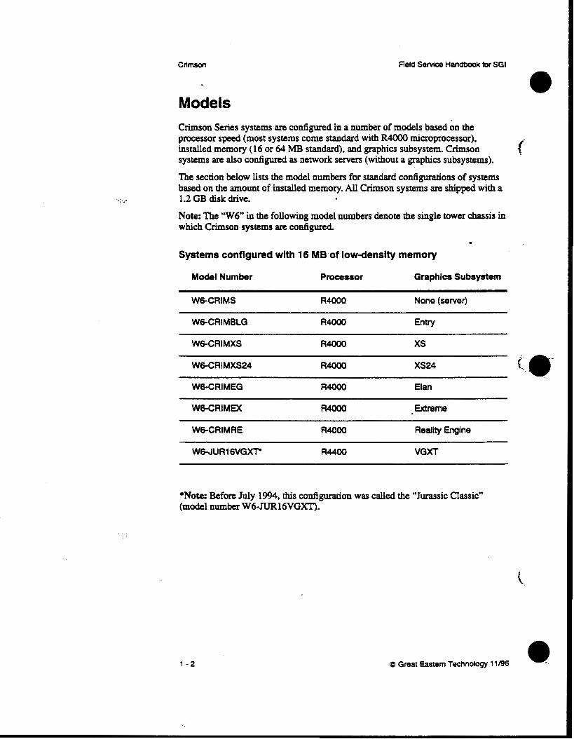
Models Crimson Series systems are configured in a number of models based on the processor speed (most systems come standard with R4OOO microprocessor), installed memory (16 or 64 MB standard), and graphics subsystem. Crimson systems are also configured as network servers (without a graphics subsystems).
The section below lists the model numbers for standard configurations of systems based on the amount of installed memory. All Crimson systems are shipped with .a 1.2GB diskdrive.
Note: The “W6” in the following model numbers denote the single tower chassis in which Crimson systems are configured.
Systems configured with 16 MB of low-density memory .
Model Number Processor Graphics Subsystem
W6-CRIMS R4000 None (sewer)
WG-CRIMBLG R4000 Entry
WG-CRIMXS R4000 xs
WG-CRIMXS24 R4000 XS24
WG-CRIMEG R4000 Elan
WG-CRIMEX R4000 Extreme
W6-CRIMRE R40W Reality Engine
W W U R 1 6 V G r R4400 VGXT
*Note: Before July 1994, this configuration was called the “Jurassic Classic” (model number W6-JUR16VGXT).
1 - 2 cb Great Eastern Technology 11196

Systems configured with 64 MB of highdensity memory
M o d s 1 Number Processor Graphics Subsystem
WWDCR64S R4000 None (server)
R4OW Entry
WWOCRMXS R40W xs
W6-4DCR64XS24 R4000 XS24
W6-4DCR64EG R4OW Elan
WWDCR64EX R40W Extreme
W6-4DCR64RE R 4 0 0 0 Reality Engine
W6-CRIMlSOVGXT R 4 4 0 0 VGXT
WG-CRIM150RE R44W Reality Engine
*Note. Before July 1994, this configuration was called the “Jurassic Classic” (model number W6-JUR64vGW.
0 Great Eastern Technology 11 I96 1 - 3

... . .
.
Crimson Field Service Handbook for SGI
EnvironmentalPhysical Specifications This section contains environmental and physical specifications for C h o n systems, which are configured in a single tower chassis.
EnvironmentaUPhysical Specifications
Operating temperature ................. 50 to 95°F (10 to 35°C)
Storage temperatart ........................... 14PF (-40 to 60°C)
Stze and Weight C W ............................................W1dth-2ln (54Cm)
Height-26" (65 cm) Depth-29" (74 cm) Weight-180 lbs (82 kg)
19" Monitor .................................... W~dth-19.2" (49 cm) Height-21.5" (54.5 cm)
Weight48 Ibs (31 kg)
16" Monitor ........... ....................... Width-15.5" (39 cm)
Depth-19.c (49 cm)
Height-16" (41 cm)
Weight47 lbs (21 kg) Depth-17" (43 cm)
Keyboard ........................................ W1 dth-20" (51 cm) . DCpth4.5" (215 cm) Height--1.75" (4.5 a)
Weight-3 Ibs (1.4 kg)
1 - 4

e
Field Senrice Handbook for SGI
Power Line voltage .................................... 104-132 VAC
200-240 VAC
current ............................................ System-20 amps at 120 VAC 10 amps at 240 VAC
Monitor-2.5 amps at 12OVAC
AC frequency range ........................ 47 to 63 Hz
Input plug ........................................ 5-20
Heat displacement ......................... System-2600 BTUs typical (maximin of 4100 BTUs/how) Monitor-512 BWs/hour
Audio Noise
Maximum 85db (typical operation)
cb Great Eastern Technology 11/96
specifications
1 - 5

. . ,. . . ..
.

Section 2-Configurations his Section contains the following configuration information for Crimson systems:
Chassis configuration
Slot assignments
Component location and jumpering for CPU board
0 Maw I03B YO contxollcr
0 Graphics subsystems
.Entry 0 xs 0 xs24 0 Elan 0 Exame(EX)
0 VGXT
0 Reality Engine (RE)
0 Moniton
0 Supported peripheral &vim
(D Great Eastern Technology 11/96 2 - 1

. .
Displaying the System Configuration
Use the hinv (hardware inventory) command to display a list of hardware configured in the system. Execute the hinv command from the Commbd Monitor (see Section 3, page 3-3) or from the IRIX system prompt.
To display a hardware con6guration list. At the I R E system prompt or the Command Monitor prompt, enter hinv. The system displays a list similar to the following:
1 50 MHz IP17 Processor FPU: MIPS R4010 Floating Point Chip Revision: 0.0 CPU: MIPS R4000 Processor Chip Revision: 2.2 On-board serial ports: 4 Data cache size: 8 Kbytes Instruction cache size: 8 Kbytes Secondary unified instruction/data cache size: 1 Mbyte Main m e m o r y size: 32 Mbytes 1/0 board, slot F: I03B Integral Ethernet: ctO, I03 Tape drive: unit 6 on SCSI controller 1: DAT Integral SCSI controller 1: Version WD33C93A. revision 9 CDROM: unit 6 on SCSI controller 0 Disk drive: unit 1 on SCSI controller 0 Integral SCSI controller 0: Version WD33C93A. revision 9 Graphics board: GR2-Elan
.
2 - 2 (D Great Eastern Technology 11/96 e.
Field Service Handbook for SGI
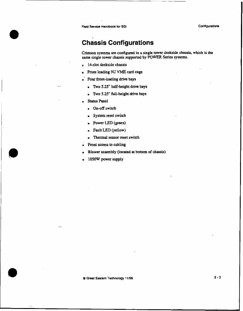
Chassis Configurations Crimson systems are configured in a single tower deskside chassis, which is the same single tower chassis supported by POWER Series systems. . 14-slot deskside chassis
.Front loading 9U VME card cage .' Four front-loading drive bays
W o 5.25" half-height drive bays
W o 5.25" full-height drive bays
0 StahlsPanel
0 On-offswitch
System reset switch
Power LED (green)
Fault LED (yellow)
Thermal sensor reset switch
i Front access to cabling
Blower assembly (located at bottom of chassis)
1050W power supply
a Great Eastern Technology 11/96 2-3

CrimsCn Field Service Handbook for SGI
Chassis-Front View (without cover)
. . ...
I , I /
I I
2 - 4 FD Great Eastern Technology 11/96
ReM Service Handbook for SGI Configurations
. ..
..
Chassis (Front View)-Comments 1.
2.
3.
4.
5.
6.
7.
8.
9.
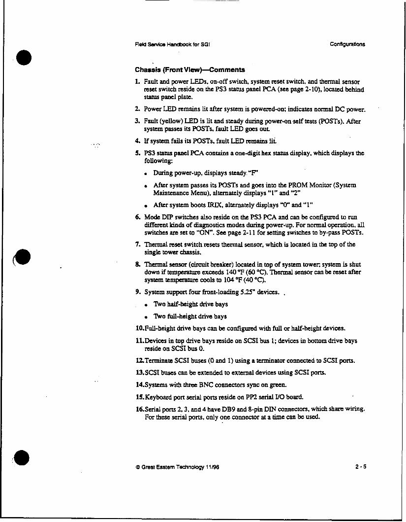
Fault and power LEDs. on-off switch, system reset switch, and thermal sensor reset switch reside on the PS3 status panel PCA (see page 2-10), located behind s t a t u s panel plate.
Power LED remains lit after system is powered-on; indicates normal DC power.
Fault (yellow) LED is lit and steady during power-on . s e l f tests (POSTS). After system passes its POSTS, fault LED goes out
If system fails its POSTS. fault LED remains lii.
PS3 status panel PCA contains a one-digit hex status display, which displays the following:
0 During power-up, displays steady. “F“
After system passes its POSTS and goes into the PROM Monitor (System Maintenance Menu), alternately displays “1” and ’2”
After system boots IRIX, alternately displays “0“ and “1”
Mode DIP switches also reside on the PS3 PCA and can be configured to nm different kinds of diagnostics modes during power-up. For normal operation, all switches arc set to “ON. See page 2-1 1 for setting switches to by-pass POSTS.
Thermal reset switch resets thermal sensor, which is located in the top of the single towa chassis.
Thd sensor (circuit breaker) located in top of system tower system is shut down if tempemhare exceeds 140 O F (a0 OC). Thennal sensor can be reset after system temperature cools to 104 OF (40 “C). System support four front-loading 5.25“ devices. .
n o half-height drive bays
’ b o full-height drive bays
1O.Full-height drive bays can be conf@xcd with full or half-height devices.
11.Devices in top drive bays reside on SCSI bus 1; devices in bottom drive bays
12Terrninate SCSI buses (0 and 1) using a terminator connected to SCSI ports. l3.SCSI buses can be extended to external devices using SCSI ports.
14.Systems with three BNC connectors sync on green. 15.Keyboard port serial ports reside on PP2 serial YO board. 16.Serial ports 2.3, and 4 have DB9 and &pin DIN connectors, which share Wiring.
reside on SCSI bus 0.
For these serial ports, only one connector at a time can be used.
(0 Great Eastern Technology 11196 2 - 5
Fidd Service Handbook for SGI
. . . .
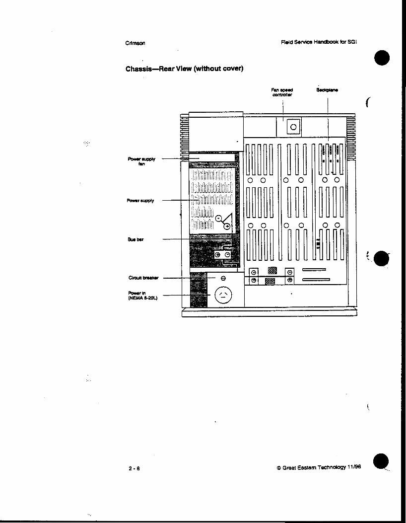
Chassis-fIear View (without cover)
J. I. :. .. .\ .. .. . . . - . . . . . . . . . . .. . . :::=;:::.:.v:: i:: { . i . .. -- .. .. ~ .. .1 ,:.: i:,, "
t
L
FM Bdcprrw
0 0
0 0 0 0 0
- IIU
2 - 6
I
CD Great Eastern Technology 11/96 @

Field Service Handbook for SGI Configuratlons
Chassis Rear VieHF--Comments 1. Power supply circuit breaker controls input power to power supply.
2. Power bus bar connects +/- 5V from power supply to backplane.
3. Power supply fan configured with power supply assembly.
4. See page 3-33 for procedures describing how to check power supply voltages.
0 Great Eastern Technology 11/96 2 - 7

Reid Senrice Handbook for SGI
Chassis-Backplane (rear view)
4 3 2 1 14 13 12 11 10 0 I ... .- ...... .-.. . ..... :
. .
. . . .
. . . .
. .
.."<
..... j :
.....
. . . . . ...
. .
I . . . : :
. . . .
.- ..... " ... ....
0 0 0 0 0 0 - :-
. .
. .
. . :
..........
..-
. :
. .
. ! . .
: ......
.- ,- ,..... . .
. .
0 0 0 0 0
J11 J13
Q Great Eastern Technology 11/96 e 2 - 8

:. .
L
Configurations ReM Service Handbook for SGI
Backplane--Comments 1. The Crimson system uses a multi-processor systems backplane
(FRU# 030-0197-OOx).
2. Remove rear cover and backplane cover to access the backplane.
3. Backplane slots comprise the foilowing buses:
0 Slots 1 4 = VME bus
0 Slots 5-8 = mu bus (vo--av)
0 Slots 9-14 = Graphics bUS
For slot assignments, see page 2-13.
4. As a general guideline, populate the VME slots from slot 1 to slot 4.
5. Jumpers located between VME slots (14) are bus grant (BG) and intempt acknowledge (IACK) jumpers. Use the following rules when jumpering the VME slots:
If any VME slot is empty, BG and IACK jumpers located to the left of the empty slot must be installed,
If a board is installed in a VME slot, the jumpers for that slot must be removed
6. If the GENLOCK board is installed in a VME slos it must reside in slot 4 and the GENLOCK jumpers (located to the left of bottom connector for slot 4) must be i n S t a l l e d .
7. "he top power bus bar COM~C~S ground from power supply to backplane at
8. The bottom power bus bar connects +5V from power supply to backplane at
9. The connectors on the backplane provide connections to the following system components:
Jl-Connects backplane to the PS3 PC& located behind status paneL
J Z - c o ~ e ~ t s backplane to SCSI bus drive bays.
J3--Supplies all power supply voltages to backplane.
J4-Supplies power to PP2 serial I/O board, located on system bulkhead
J6-Supplies power to cooling fans (connects to fan speed controller, located
J7-Connects to thermal sensor located in the top of the chassis.
locations J1 land J13.
locations J10 and J12.
on backplane).
2 - 9

. ...
Crimson
Chassis-PS3 Status Panel PCA
Field Service Handbook for SGI
0 0 0
J -;+----- I
hunm 0
P S - C o m m e n t s 1. The PS3 displays status information about the system; it also can be configured
to assist in troubleshooting system problems.
2. To view the system s t a m s display or voltage LEDs. set the m d e DIP switches, or use the voltage test points, you must remove the PS3 board from the chassis. To remove the PS3:
Remove any devices in the top two drive bays.
Remove the screw holding the PS3 status panel assembly into the chassis.
Warning: When the PS3 is .not installed in the chassis and the system is powered-on, be carelid not to short out the PS3.
3. A ribbon cable connects the PS3 s t a t u s panel to the connector at location J1 on the system backplane (see page 2-8).
t
2 - 1 0 Q Great Eastern Technology 11/96
.. .::
Field Service Handbook for SGI Configurations
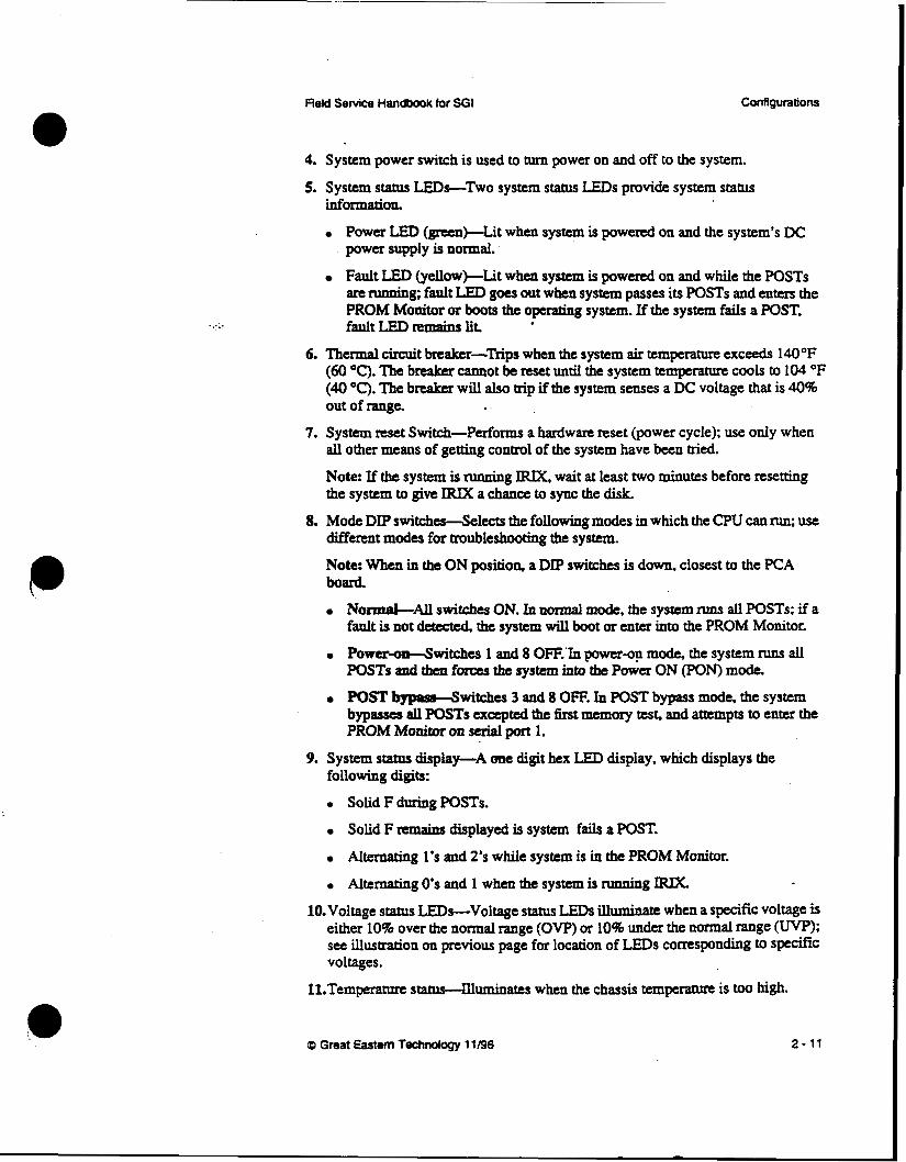
4. System power switch is used to turn power on and off to the system.
5. System status LEDs-Two system status L E D s provide system status information.
Power LED (green-it when system is powered on and the system's DC power supply is normal.
Fault LED (yellow)-Lit when system is powered on and while the POSTS an ruaning; fault LED goes out when system passes its POSTS and entcrs the PROM Monitor or boots the operating system. If the system fails a POST, fault LED remains lit
6. Thermal circuit haler-Trips when the system air temperature exceeds 140OF (60 "0. The breaker cannot be nsct until the system temperature cools to 104 OF (40 "C). The breaker will also trip if the system senses a DC voltage that is 40% out of range. * .
7. System reset Switch-Performs a hardware reset (power cycle); use only when all other means of getting control of the system have been tried. Note: If the system is running IRK, wait at least two minutes before resetting the system to give IRIX a chance to sync the disk.
8. Mode DIP switches-Selects the following modes in which the CPU can run; use different modes for troubleshooting the system.
Note. When in the ON position, a DIP switches is down, closest to the PCA board.
N0rznaI-M switches ON. In nonnal mode, the system runs all POSTS; if a fault is not detected the system will boot or enter into the PROM Monitor.
Power+&witches 1 and 8 OFE'In power-on mode, the system runs all
POST bypam4Mtches 3 and 8 OFF. In POST bypass mode, the system
POSTS and thg! forces the system into the Power ON CpON) mode.
bypasses all POSTS excepted the first memory tess and attempts to enter the PROM Momtor on serial port 1.
9. System status display-A me digit hex LED display, which displays the following digits:
0 Solid F during P O S T S .
Solid F remains displayed is system fails a POST. Alternating 1's and 2's while system is in the PROM Monitor.
Alternating 0's and 1 when the system is Nnning IRM- 1O.Voltage status LEDs-Voltage s t a t u s L E D s illuminate when a specific voltage is
either 10% over the normal range (OW) or 10% under the normal range (W>; see illustration on previous page for location of LEDS corresponding to speflc voltages.
11.Temperanae status-lllumina!es when the chassis temperature is to0 high.
cp Great Eastern Technology 11/96 2 - 11
-:_ . .
. .
CrlmsoCr
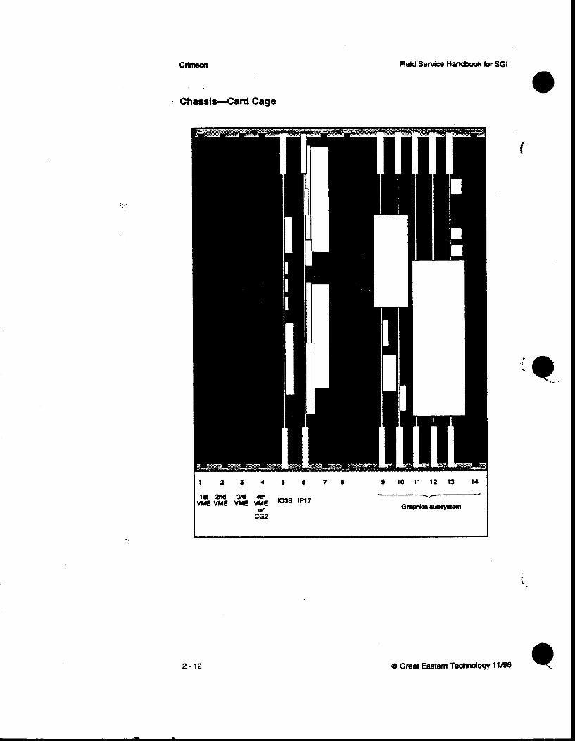
Chassis-Card Cage
Field Service Handbook for SGI
1 2 3 4 5 6 7 0
CGZ or
9 10 11 12 13 14
2 - 1 2 Q Great Eastern Technology 11196 4
Configurations
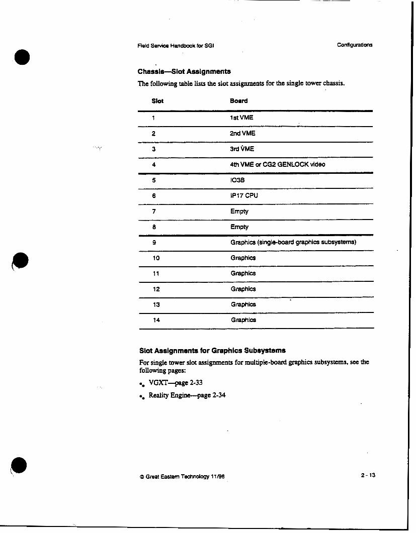
Chassis-Slot Assignments The following table lists the slot assignments for the single tower chassis.
Slot Board
1 lstVME
2 2nd VME
3 3rd QME
4 4th VME or CG2 GENLOCK video
5 1038
6 IP17 CPU
7 Empty
8 Empty
9 Graphics (single-boad graphics subsystems)
10 Graphics
11 Graphics
12 Graphics
13 Graphics
14 Graphics
Slot Assignments for Graphics Subsystems For single tower slot assignments for multiple-board graphics subsystems, see the following pages:
VGXT-pge 2-33
Reality Engine-page 2-34
@ Great Eastern Technology 11 /9S 2 - 13
Slot Assignments-Comments 1. See table on previous page for slot assignments.
2. Card cage is located behiud the system bulkhead.
3. Conftgure V M E controller boards in slots 1-4
0 h~tall VME boards be-g with Slot 1.
"here must be either a board installed in a slot or jumpers installed between the beginning of the VME backplye and the last VME board (see page 2-8 for jumper locations). ._...
Slot 4 may contain either a VME board or a CG2 genlock video board.
4. The 103B must be install into slot 5. . 5. The Crimson CPU board must be installed into slot 6.
6. The P17 Crimson CPU can not run with MC2 memory board.
7. Single-board graphics subsystems reside in slot 9.
8. Boards comprising the VGXT and Reality Engine graphics subsystem are installed in slots 9-14.
f
2 - 14 0 Great Eastern Technology 11/96 e

... ..
Field Service Handbook for SGI Conlgurations
CPU Board Crimson systems are configured with a single-processor IP17 CPU board, which is configured with two different MIPS microprocessors. The microprocessor is permanently mounted on the CPU board. 0 100MH~R4000
16 K primary cache (8 K datal8 K instruction)
1 MB secondary cache
0 15OMHZR4400 32 K primary cache (16 K datal16 K instruction)
1 MB secondary cache
CD Great Eastern Technology 11/96 2 - 15

CfimsOn ' Reld Service Handbook for SGI
CPU4P17 Component Locations
I I C W aacibtor
( 5 0 MHz)
CPU
C W fur
2 - 16 Q Great Eastern Technology 11/96

Field Service Handbook for SGI Configurations
IP174omments
1. The IP17 CPU resides in slot 6.
2. Because the MIPS R4xOO microprocessor runs extremely hot. a heat sink and cooling fan are mounted directly on the microprocessor.
3. CPU cooling fan C O M C C ~ ~ to cooling fan power connector at location JSPI.
4. The P I 7 must run with a I03B YO controller.
5. S u i a l YO connector connects CPU board to PP2 serial YO panel (containing keyboard. mouse, and serial ports). which is mounted on system bulkhead (see page 2-41.
6. When the system is powered-on or reset. the L E D s on the IP17 cycle through the POSTS. After the system passes its POST and displays the System Maintenance Menu, the LEDs display the following pattern:
7. A&r the system has boot the IRIX operating system, the CPU LEDs display the following pattern during normal operation:
CD Great Eastern Technology 11/96 2 - 17
L

Crlmsocr Field Sefvlce Handbook br SGI
......
Memory Crimson systems use 8Ons, 72-pin single in-line memory modules (SIMMs), which reside on the IP17 CPU board. These SI"s provide e m r comction checking (ECC) funtionality.
32 slots, physically organized in four groups of eight slots.
Slots are logically organized in to banks; each bank consists of two S I " slots.
Each group of slots consists of banks 1 - 4.
Systems support 2 MB (low-density) and 8 MB (high-density) SIMMs.
Note: Crimson systems use the same SI"s used in POWER Series systems. .
l l I I I '
. . . .
............................ .......... .......................................... " ................. .....................................
B M k 2 4 - = P I
Bank4 4 P I P
" .....-....... " ............. ............... ............ ...................... .......... ._ _.I .... I ........ -.
P -1 I ! I
- Bonk1
- B a n k 2
- Bank3
- Bulk4
- Bu*l
- Bulk2
- B.nk3
- m4
i
2 - 18 Q Great Eastern Technology 11196

Reid Senrice Handbook for SGI Configurations
Memory-Rules for Populating Memory Slots
1. Install eight SI"s at a time, populating a l l slots that comprise a bank 2. Populate consecutive banks, beginning with bank 1 and ending with bank 4.
3. To mix 2 MB and 8 MB SI"s on an IP17 CPU board. follow these rules:
Populate a bank with the same-capacity SI"s.
Install 8 MB SIMMs in the lowest numbered banks
(0 Great Eastern Technology 11 /96 2 - 19

field Service H~dboolc for SGI
I/O Board
1038 Component Locations
...
2 - 2 0
P KaQ3 Monitor
PROM
EPROM.
f
(0 Great Eastern Technology 1 1196 e

ReM Service Handbook for SGI Conflgurations
1. "he I03B board resides in slot 5.
2. The I03B has two SCSI controllers on-board.
3. The I03B has one Ethernet control on-board.
4. For Ethernet and SCSI fuses, use a 2A 125V replacement fuse.
5. Both SCSI controllers use the same fuse. 6. The PROM Monitor logic resideson EPROMs on the I03B.
7. The connector at location J3 is the connector for the second SCSI controller (SCSI bus 1).
the PROM Monitor password aud the Ethernet addrcss. 8. The NVRAM chips holds the PROM Monitor environmental variables, including
9. For normal operation, use the following settings for I03B jumpers:
c2P4 pJ J408 E l
K8G3 El M
G7A8
(D Great Eastern Technology 11196 2 - 21
Crimson Field Service Handbook for SGI
.. .... . .
Graphics Subsystems Crimson systems can be configured with seven different graphics subsystems:
Entry
0 xs e XS24
0 Elan
Extreme(EX)
VGXT Reality Engine (RE)
Note: The Entry, XS, XS24, and Elan graphics subsystems consist of the same field replaceable units (FRUs) as the graphics supported by Indigo systems. The Extreme graphics subsystem consists of the same FRUs supported by Indigc? EX systems.
In both cases, adapters are required to configure these graphics subsystems in a Crimson chassis.
t
Single-Board Graphics Subsystems The Entry, XS, XS24, Elan, and EX graphics subsystems can be considered “single-board” graphics subsystems because they consume one slot in the Crimson chassis. However. these graphics subsystems consist of a motherboard, daughter cards, and adapter@).
Multiple-Board Graphics Subsystems
The VGXT and RE graphics subsystems consist of three to five graphics boards. Boards in these subsystems have a 9U VME format, and each board consumes a different slot in the Crimson chassis.
.. . . . ..
2-22

Field SenAce Handbook for SGI Configurnlions
Graphics-MGl Adapter The MGl VME adapter adapts single-board graphic subsystems to the Crimson's 9U VME format The graphics subsystem fits into the MG1 frame and connects to the connector on the MG1 PC4 board., which also contains logic ASICs that enable the single-boards graphics.subsysteems to run in the Crimson.
. . . . . . . . . . . . . . . . . . . . . . . . . . . . . . . . . . . . . ....................................... .......... " ._ ........ " ... " .......... . . . . . . . . . .. .................................. . . . . . . . . . ...................................
.. : .. : :
:. .... ... ,
_" ..-.... - ....... . .-__... ..."._.. ..... _.. : .--..-. " ... ̂ "1
........ .............. ....................................... ,:.:..::.:.:. 3 .I............. ':':.... ...... .. _ _. .,._..
....................
..................................................... f--..:.:::
... .................. ........... . .-...... ..__.... " ... .............................. .- - ....... ...... I I I n 1 -'x I -..... I
I uuu -' I
1 - MGltnme
- Mol PcAboud
Comments
1. The MGl is required to adapt all single-board graphics subsystems (Entry, XS, XS24. Elan, and EX) to a Crimson chassis.
2. The video cable for single-board graphics subsystems connects the subsystem to a 13W3 connector mounted on the system bulkhead at the front of the chassis.
3. Any ejector clips on an LG2 or GR2 board must be nmoved before those boards can be installed in the MG1 adapter.
CD Great Eastern Technology 11/96 2 - 23

ClimsOn SGI
Graphics-GRZ Motherboard The XS, xS24, and Elan graphics subsystems are configured with a GFU graphics motherboard. The GR2 can be configured with one or four GE7 Geometry Engines and one or three VM2 video memory modules. Merent graphics subsystems wil l be configured with different quantities of GE7s and VM2s.
. ._.
Conmctor to MG1 adapter
@
d ' 1 '
I ..... "".."-..- : ; w . . . .
BD
2-24
I I I I -.nn I IIII
(0 Great Eastern Technology 11/96
...
Field Service Handbook for SGI coilflguranons
3. In graphic subsystems configured with one VM2 memory module, the vM2 must reside in location P14.
4. For normal operation, jumper at location P% must be installed (jumper is used for manufacturing testing).
5. If using a GR2 graphics motherboard from an Indigo, the ejector clips must be removed before installing the GR2 into the MG1 adapter.
Q Great Eastern Technology 11 /96
Crimson Field Service Handbook for SGI
Graphics-Entry
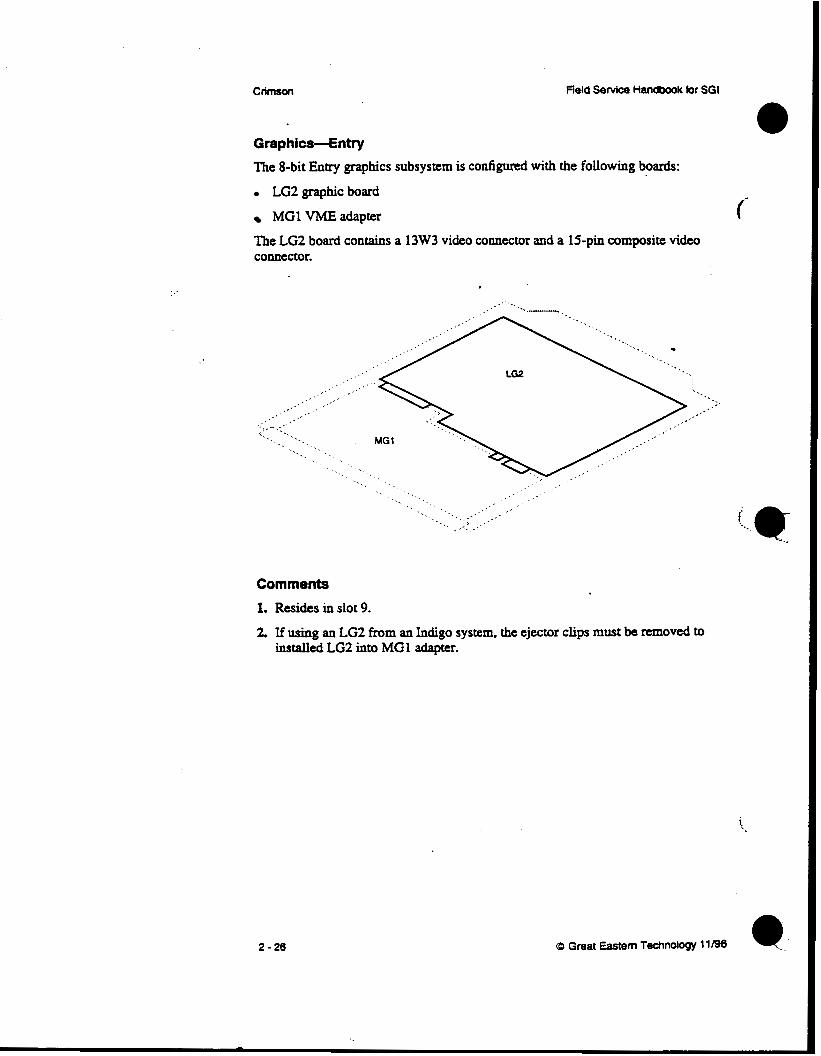
The 8-bit Entry graphics subsystem is configured with the following boards:
0 LC2 graphic board
MG1 VME adapter
The LG2 board contains a 13W3 video connector and a 15-pin composite video connector.
Comments 1. Resides in slot 9.
2. If using an LG2 from an Indigo system, the ejector clips must be removed to installed LG2 into MGl adapter.
2 -26
... . . .
Field Service Handbook for SGI Configurations
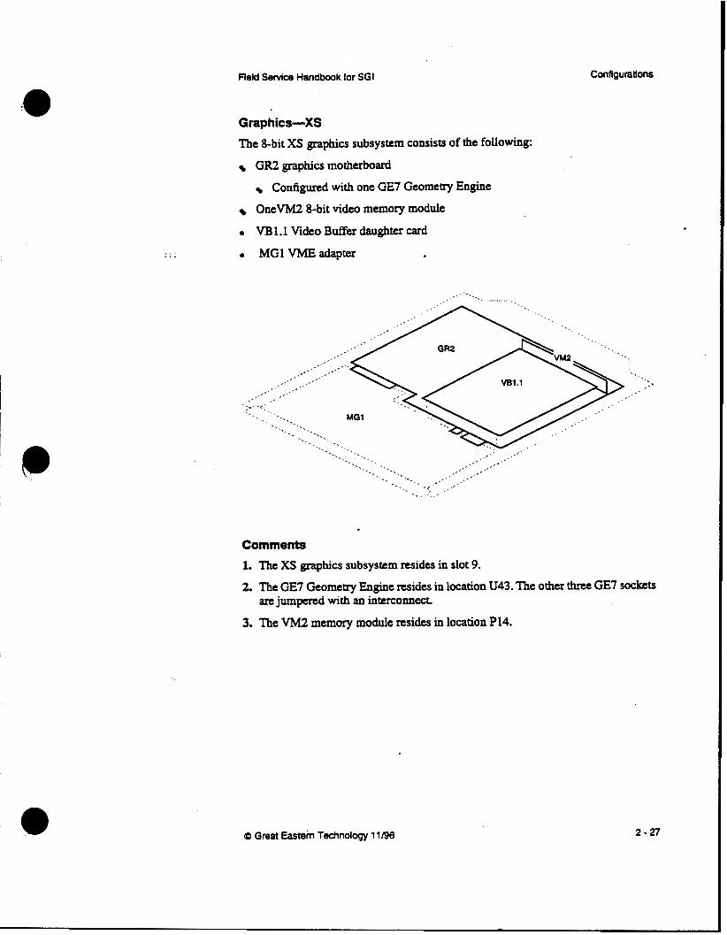
Gmphics-XS The 8-bit XS graphics subsystem consists of the following:
GR2 graphics motherboard
Configured with one GE7 Geometry Engine
OneVM2 8-bit video memory module
0 VB1.l Video Buffer daughter card . MG1 VMEadapter
. .. , ... '. . . . . .. ..... . .
Comments
1. The XS graphics subsystem resides in slot 9.
2. The GE7 Geometry Engine resides in location U43. The other three GE7 sockets are jumpemd with an interconnect
3. The VM2 memory module resides in location P14.
(0 Great Eastem Technology 11/96 2-27

CfimsOn ' Reid Service Handbook for SGI
Graphics-XS24
The 24-bit XS24 graphics subsystem consists of the following:
GR2 graphics motherboard
Configured with one GE7 Geometry Engine
Three VM2 8-bit video memory modules
0 VBl.lVideoBufferdaughtercard
MGlVMEadapter No& The XS24 graphics subsystem is the same configuration as the XS with the addition of two VM2 memory modules. .
Comments
1. The XsP graphics subsystem resides in slot 9. 2. The GE7 Geometry Engine resides in location U43. The other three GE7 sockets
are jumped with an interconnea
performance); single VM2 must reside in location P14. 3. The system will operate with one VM2 memory module (with downgraded
i
2 - 28 (D Great Eastern Technology 11/96
. ._.
Field Service Handbook for SGI Configurations
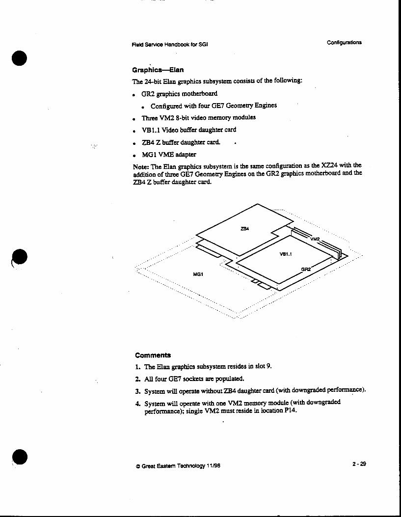
Graphics-Elan
The %bit Elan graphics subsystem consists of the following:
GR2 graphics motherboard
Configured with four GE7 Geometry Engines
Three VM2 8-bit video memory modules
0 VB 1.1 Video buffer daughter card
0 Z B 4 Z b u f f e r d a ~ g h t e r ~ d
0 MGl V M E a d a p ~
Note: The Elan graphics subsystem is the same configuration as the XZ24 with the addition of thee GE7 Geometry Engines on the GR2 graphics motherboard and the ZB4 Z buf€er daughter card.
Comments 1. The Elan graphics subsystem resides in slot 9.
2. All four GE7 sockets arc populated.
3. System will operate without ZB4 daughter card (with downgraded performance).
4. System will operate with one VM2 memory module (with downgraded performance); single VM2 must reside in location P14.
cp Great Eastern Technology 11/96 2-29

crimson Field Service Handbook for SGI
Graphics-€xtreme
The Extreme (EX) graphics subsystem is a three-board graphics subsystem, which requires two adapters that enable it to be configured in a Crimson chassis.
GUl graphics unit-Contains eight GE7 Geometry Engine ASICs.
RUl raster unit-Contains two RE3 raster engine ASICs.
VB2 video board-Conrains the 13W3 video connector. GENLOCK connector, and a connector for graphics options such as stereo glasses. The VB2 also has a video expansion pon AB 1 GI0 adapter-Adapts EX graphics subsystem (physically and logically) to MG1 adapter. EX boards connect to AB1, which is connected to the MG1.
MG1 VME adapter-Adapts EX subsystem and AB 1 adapter to Crimson’s 9U VME format.
Note: The EX graphics subsystem (GUl, RU1, and 0 2 ) is also supported by Indigo2 systems.
Comments
1. The EX graphics subsystem resides in slot 9.
2. RU1 and VB2 boards do not have connectors
RU1 board connects to GU1 board (two connectors)
VB2 board connects to RU1 board (two C O M C C ~ ~ ~ S )
3. All three graphics boards must be installed for system to operate.
2-30 0 Great Eastern Technology 11/96

Configurations Field Service Handbook for SGI
GraphiCs-VGXT The VGXT graphics subsystem is a four-board subsystem configured with the following boards: . GM3 Graphics manager
GE6 Geometry Engine subsystem
RM3 Raster manager
DG1 Display generator
GM3 GE6 RM3 OG1
I I I I \ 1
I GI3 -
I
(D Great Eastern Technology 11 /96 2 - 31

. . . . ..
. .
Crimson Field Senrice Handbook for SGI
VGXT-Comments 1. To view the power-on diagnostics for the graphics subsystem, connect an ASCII
terminal to the DB9 connector on the GM3 board. To enter the PROM Monitor, enter the terminal’s “Break” key sequence.
2. While in the PROM Monitor (after system successfully passes its POSTs), the eight L E D s on the GM3 board will display the following pattern:
0 =On
0 = o n
. 3. The GI3 edge connector connects the GM3 to the GE6 board.
4. The RIS edge connector connects one or two RM3 boards to the DGl board.
5. VGXT graphics require one RM3 boar& systems can be configured with a
6. The RM3 has a 36-LED status display. After the system successfully completes
second RM3 board.
its POSTS, these LEDs display the following pattern:
1 -
8 -
16 -
36 -
2-32
0 = o n 0 -on
CD Great Eastern Technology 11196

ReM Sewice Handbook for SGI Configurations
7. The DG1 board has five video YO connecton (from top to bottom):
0 GENLOCK SWC Output . Alpha output Video . RGB Video output and sync to monitor (use internal RGB ribbon cable,
. Super VHS and composite video (use on systems with EV1 video option)
GENLOCKRGB input .
FRU# 018-0183-001)
. ._.
VGXT Graphics-Slot Assignments The following table contains slot assignments for the VGXT graphics subsystem for crimson systems:
Slot Graphics board
11 Optional video
13 ~
First RM3
14 DG1
(0 Great Eastern Technology 11/96 2-33
CIimsOn Field Service Handbook for SGI
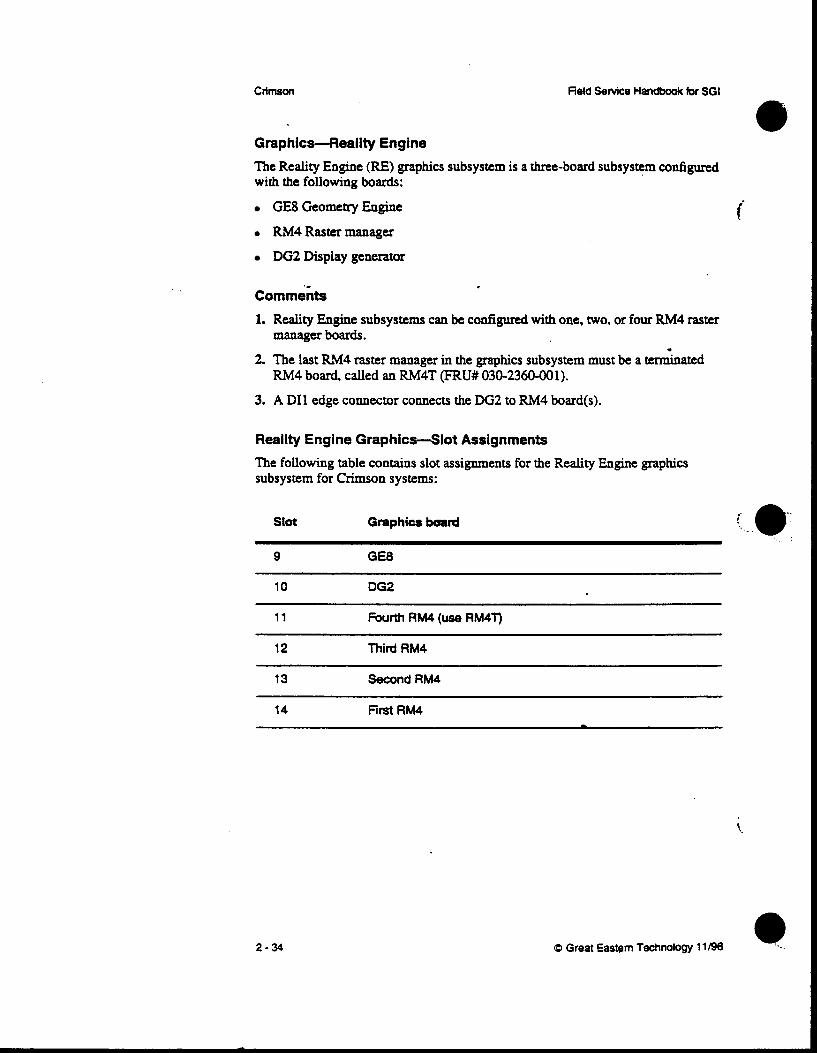
GraphicHeality Engine The Reality Engine (RE) graphics subsystem is a three-board subsystem configured with the following boards:
GE8 Geometry Engine
RM4 Raster manager
DGZ Display generator
C o m m e k 1. Reality Engine subsystems can be configured with one, two, or four RM4 raster
manager boards. . 2. The last RM4 raster manager in the graphics subsystem must be a terminated
RM4 board, called an RM4T (FRU# 030-2360-001). 3. A DI1 edge connector connects the DG2 to RM4 board(s).
Reality Engine Graphics-Slot Assignments The following table contains slot assignments for the Reality Engine graphics subsystem for Crimson systems:
Slot Graphics buad
9 GE8
10 DG2
11 Fourth RM4 (use RM4T)
12 Third RM4
13 Second RM4
14 First RM4 -
i
r' .. e: 1 . .
t
2-34 Q Great Eastern Technology 11/96

L
Field Setvice Handbook for SGI Configurations
Monitors See the following table for compatibility information for monitors supported by Crimson systems:
Manufacturer Input Si20 Manufacturer Model # SGI FRU # Connector
16" a n y GDM-163OSG 933OO40 BNC'
1 9' H i t a c h i CM2086A3SG 9330042 BNC
19' Hitachi CM2086A3CD 9330043 BNC
1 9' Mitsubishi HL7965KW-SG 9330812 BNC
19' a n y GDM-POD1 1 933081 8 13W3
19' Sony GDM-1930SG 9330041 13w3
~~
Note: Momtom with the manufacturer model number ending with "SG have an SGI logo on the front bezel. Monitors with "CD" in the model number do not have an SGI logo.
Monitor Termination Switches
Most SGI monitors witp BNC input connectors have impedane switches used to tcxminate the video signals. These tennination switches are a push-button. toggle type usually located under each BNC connector. Switches can be set in the following two positions:
When the switch is in the "in" position (75 ohm), the signal is terminated.
When the switch is in the "out"p0sition (High), the signal is not terminated.
For single-monitor systems. all switches should be set in the "in" position so that video signals are terminated With daisythained monitors, only the last monitor should be terminated. If a monitor is incorrectly terminated the color may be incorrect or the video display may be distorted. When troubleshooting a monitor problem, make s u r e the tcxmination switches arc set correctly, depending on the specific configuration..
@ Great Eastem Technology 11/96 2-35
Crimson
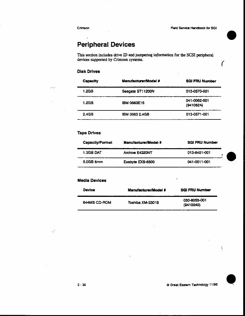
Peripheral Devices This section includes drive ID and jumpering information for the S a peripheral devices supported by Crimson systems.
( Disk Drives
. ... 1.268 Seagate ST1 1200N 01 3-0570-001
1.268 IBM W E 1 5 041-0062-001 (941 0824)
2.4GB IBM 0663 2.468 01 3-0571 -001
Tape Drives
Capacity/Format ManufacturerModel # SGI FRU Number
1.368 DAT Atchive E432ONT 01 3-8451 -001
5.OGB 8mm ExabyteM&8500 041-0011-001
Media Devices
Device Manufactumr/Model Y SGI FRU Number
644MB CD-ROM Toshiba XM-3301 B
2 - 36
Field Service Handbook for SGI Configurations
. .
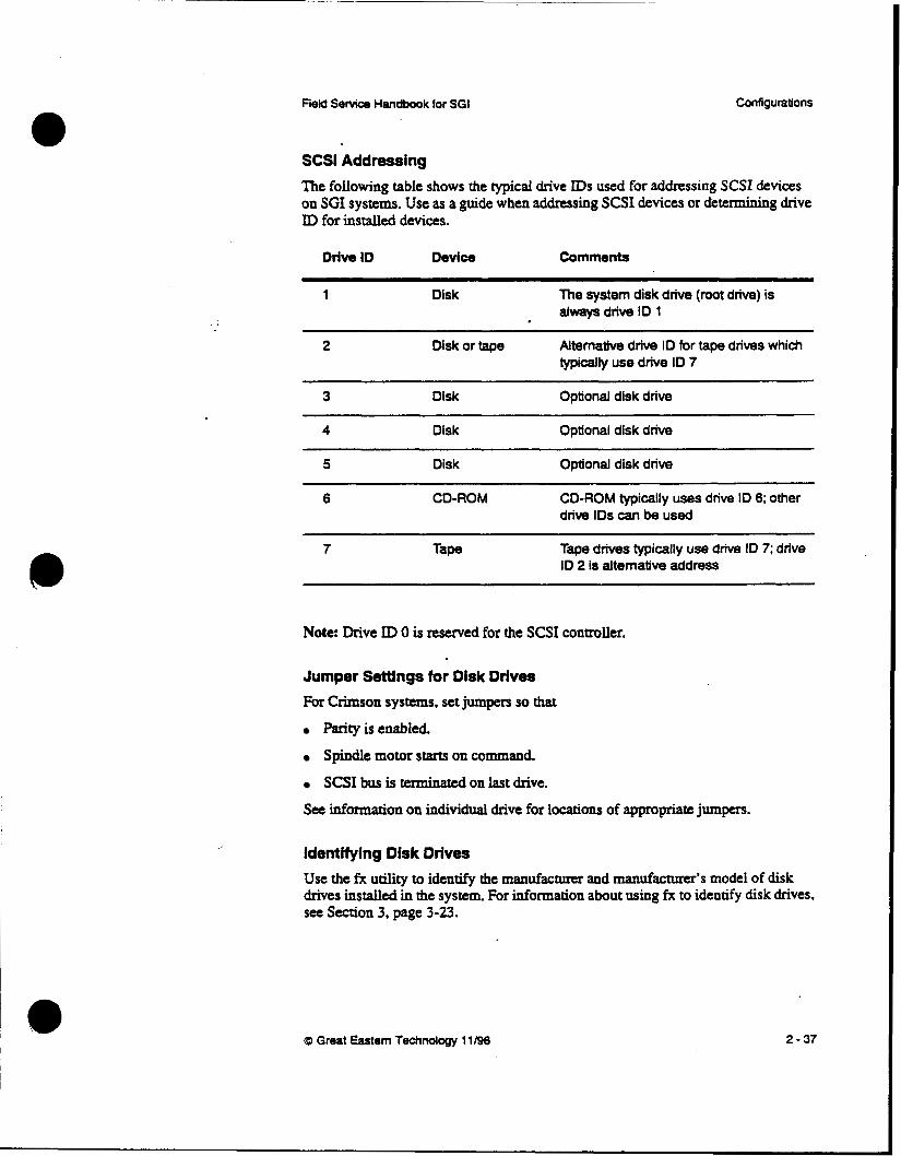
SCSI Addressing
The following table shows the typical drive IDS used for addressing SCSI devices on SGI systems. Use as a guide when addressing SCSI devices or determining drive ID for installed devices.
Driw ID Device Comments
1 Disk The system disk drive (foot drive) is always drive ID 1
2 Disk of tape Alternative drive ID for tape drives which typically use drive ID 7
3 Disk Optional disk drive
4 Disk Optional disk drive
5 Disk Optional disk drive ~~ ~~ ~~~~~ ~ ~~~ ~
6 CD-ROM CD-ROM typically uses drive ID 6; other drive IDS can be used
7 Tape Tape drives typically use drive ID 7; drive ID 2 is alternative address
Note: Drive ID 0 is reserved for the SCSI controller.
Jumper S d n g s for Disk Drives For Crimson systems, set jumpers so that
Parity is enabled.
Spindle motor starts on command.
SCSI bus is tcnninated on last drive.
See information on individual drive for locations of appropriate jumpers.
Identifying Disk Orlves Use the fx utility to identify the manufacturer and manufacturer’s model of disk drives installed in the system. For information about using fx to identify disk drives. see Section 3, page 3-23.
(D Great Eastern Technology 11/90 2 - 37

Crimson Field Service Handbook for SGI
. .
Disk Drives-1 GB 3.5" SCSI-2
Seagate ST1 1200N
s c s l CQlmrm
I
Pill
2-38
' 1 +
0
S c s l Rmrr
I
1 0 0 TP 0 0 TP 0 0 ss
J2 z z 0 0 ME 5 0 Ds
8 0 0 Rs
I 1
JS .
J6 LED
F3
4 m1
-
i
a3 Great Eastern Technology 11/96 *
. .
Field Service Handbook for SGI
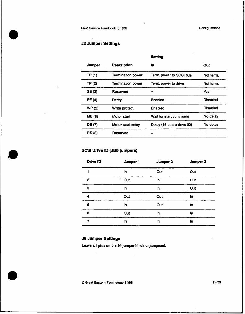
J2 Jumper Settings
Setting
Jumper . Description In
Configurations
Out
Tp (2) Termination power Term. power to drive Not term.
ss (3) Reserved - Yes
PE (4) p=w Enabled Disabled
wp (5) Write protect Enabled Disabled
ME (6) Motor start Wait for start command No delay
SCSl Drive ID (JB5 jumpers)
Drive ID Jumpr 1 Jumper 2 Jumper 3
1 In out out
* out out
3 In In out
4 Out out In
5 In out In
6 Out In In
7 In In In -
J6 Jumper Settings
Leave all pins on the J6 jumper block unjumpered.
CD Great Eastem Technology 11196 2-39

. .
Disk Drives-I GB 3.5" SCSI-2
IBM 0663E15
2-40
Field Service Handbook for SGI
1
\
~~ ,''\\\\I
\
0 0 0 0 0 0 0 0 0 0 0 0 0 0 0
1 2 3 4 5 6 7 6
Q Great Eastern Technology 11/96 111
Field Senrice Handbook for SGI Configurations
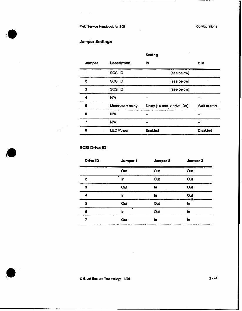
Jumper Settings
Setting
Jumper Description In Out
1 SCSl ID (see below)
2 SCSl ID (see below)
3 SCSl ID (see below)
4 WA - - 5 Motor start delay Delay (10 s8c. x drive ID#) Wait to start
6 WA
7 WA - 8 LED Power Enabled Disabled
- -
SCSl Drive ID
Drive ID Jumper 1 Jumper 2 Jumper 3
1 Out out out
2 In Out out
3 Out In out
4 In In out
5 out Out In
6 In out In
7 Out In In
~~~ ~ ~~~
-
0 Great Eastern Technology 1 1 /96
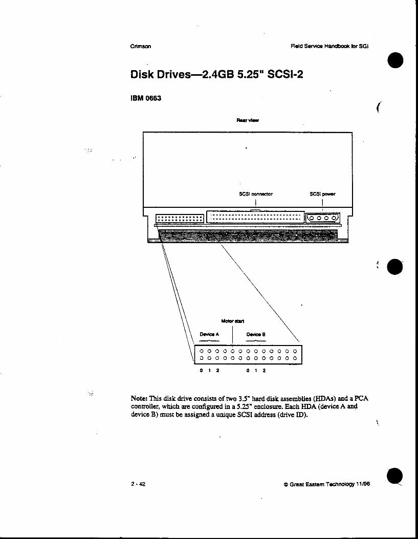
Disk Drives-2.4GB 5.25" SCSI-2 -
IBM 0663
.. ...
. . .. ..
\I 0 0 0 0 0 0 0 0 0 0 0 0 0 0 0 0 0 0 0 0 0 0 0 0 0 0
Note: This disk drive consists of two 35" hard disk assemblies (HDAs) and a PCA controller, which are configured in a 5.25" enclosure. Each HDA (device A and device B) must be assigned a unique SCSI address (drive ID).
2 - 4 2 0 Great Eastern Technology 11198
.:::.:: .'...'
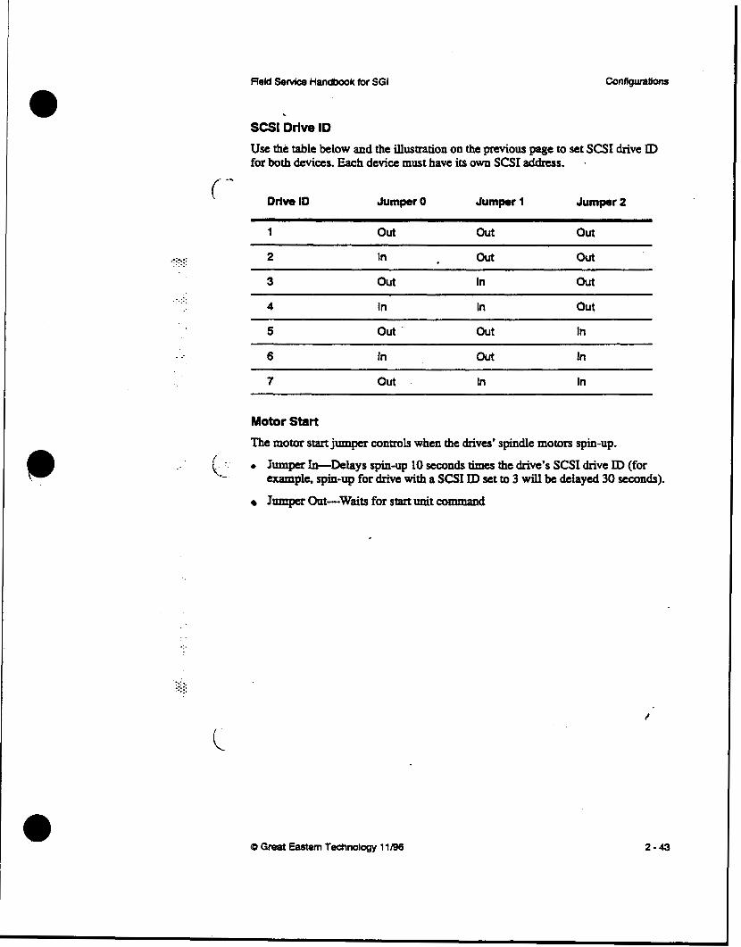
SCSI Drive ID
Use the table below and the illustration on the previous page to set SCSI drive ID for both &vias. Each device must have its own SCSI address. .
( -- Drive ID Jumper 0 Jumper 1 Jumper 2
1 Out Out Out
2 In Out Out
3 Out In Out ... . . . . .
4 In In out 5 out . Out In
6 In out In
7 Out In In
Motor Start
The motor start jumper controls w.hen the drives' spindle motors spin-up.
.. ' (: -.- 0 ~mnper ~,.+bhys @-up 10 seconds times the d r i ~ e ' s SCSI drive ID (for ._ . example, spin-up for drive with a SCSI ID set to 3 will be delayed 30 seconds).
Jumper Out-Waits for start unit command
..
CD Great Eastern Technology 11/96 2-43
CrlmsOn field Service Handbook Rr SGI
:.... -.- -.-.-:
. . :.:.
..
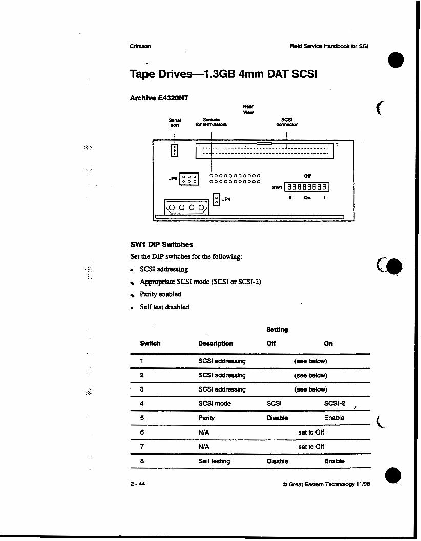
Tape Drives-1.3GB 4mm DAT SCSI
Archive E4320NT
I =I’ 00000000000 on JP6 ::: 00000000000 SWl-1
SW1 DIP Switches
Set the DIP switches for the following:
0 ScsIaddnSsing
Appropriate SCSI mode (SCSI or SCSI-2)
Parityenabled
0 self test disabled
1 ~~~ ~~ ~
S a l addressing (see below)
2 SCSl addressing (see b e l o w )
. 3 SCSl addressing Wow)
4 SCSl mode Scsl Scsl-2 , 5 MtY DsaMe Enable
6 . set to Off
7 N/A set to Off
0 Self testing D i e Enable
2-44 (D Great Eastern Technobw 11196

_. . . . .
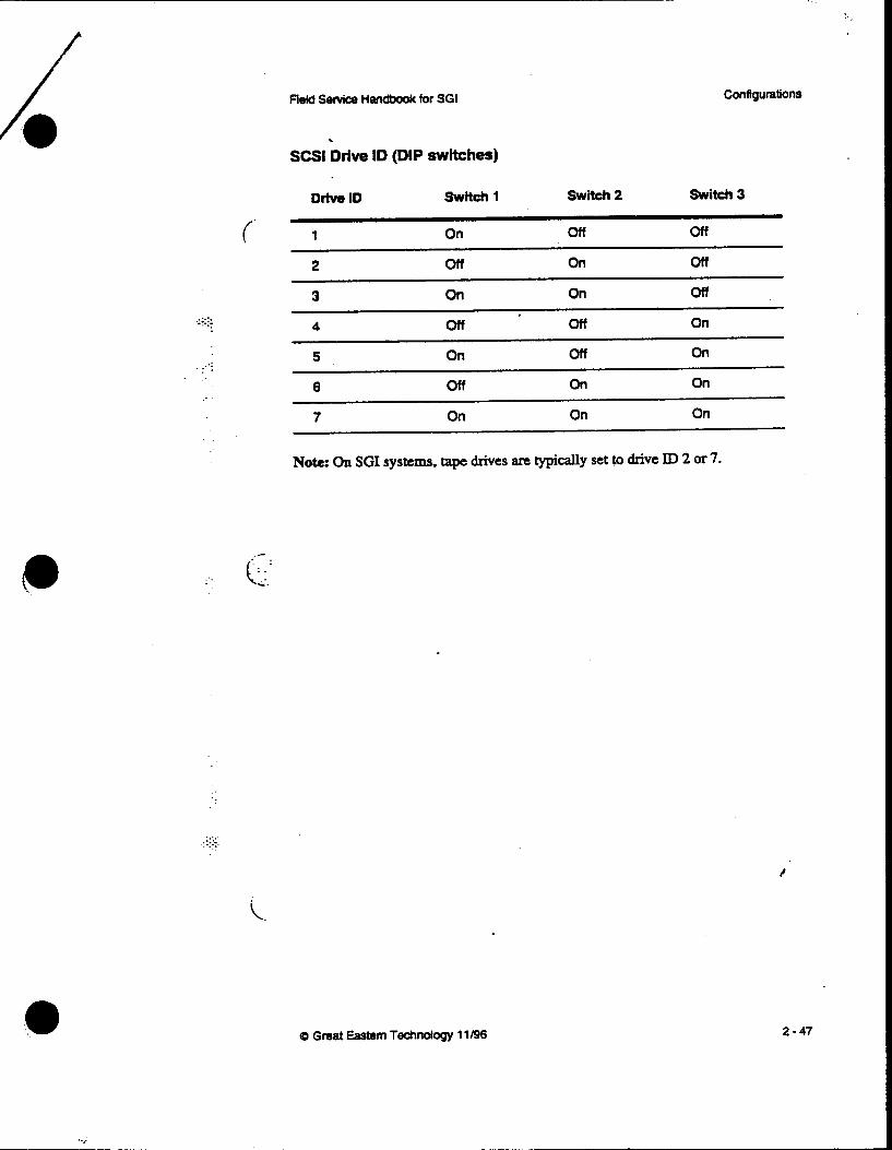
SCSI Drive ID (SW1 DIP switches) To use external SCSI addressing, set swi tches to drive ID 0.
(- Drive ID switch 3 switch 2 switch 1
0 off off off
1 On off off
2
3 On On off
4 off On
5 On off On
6 off On On
7 On On On
N o h On SGI systems, tape drives & typically set to drive ID 2 or 7.
_. . : (;-.... JP6 Jumpers
The JP6 jumper block also specifies SCSI addressing. Leave these jumpers out and use SW1 DIP switches to set the drive ID. For external SCSX addressing. attach the SCSI addressing cable on the drive sled to JP6jlrmperbaakThe~eIDwillbedetcrmiaedthedrivebayinwhichtheQive isinstalled
..>: . . : ..
JPllTminatlon dumper
. JP4 Terminator Power Terminated Untenninabd
0 Grea! Eastern Technology 11/96
/
2-45

::::::: ... . ..
.: '.
. .
CllmsOn Field Servke Handbod< for SGI
Tape Drives-5GB 8mm SCSI
Exabyte EXB-8500 (Full Height)
S C S l o o m a o r I
I '
I I I I
P3 Jumpers The P3 jumper block also specifies SCSI addressing. Leave these jumpers open and UseDIPswitchcstosetthedriveID.
. . . .
:i. ...-. .. .. ..
2-46 0 Great Eastern Technology 11/96
c
A
i.
. . - . . .
Field Service Handbook for SGI
SCSl Drive ID (DIP switches)
Configurations
Drive ID Switch 1 Switch 2 switch 3
(- 1 On off off
2 off On off
3 On On off
4 off off On
5 On off On
off on On
7 On On On
Note: On SGI systems, tape drives are typically set to drive ID 2 or 7.
. . . . . .e..- .....'
Q Great Eastern Technology 11/96 2-47

CfimsOrr
. . . . ..
..
. .
- CD-ROM D r i v p M B
Toshiba XM-3301 B
I I ~ 0 0 0 0 0 0 0 0 0 0 0 ~ 0 0 0 0 0 0 0 0 0 0 0 1
J7 Jo 1
f
-.-
c
2-48 (D Great Eastern Technology 11/96 4

Reld Senrice Handbook for SGI Configurattons
f
.--.. . .
SI Jumper Settings)
Sating
Jumper Description . In Out
ID1 (see below)
ID2 SCSl addressing (see below)
ID4 SCSl addressing (see below)
parity parity Checking Enabled Disabled
Termination Terminator Power TeFinated Untenninated
SCSl Drive ID
Drive ID Jumper ID1 Jumper ID2 J u m p ID4
1 In Out out
(. . 2 Out In out
3 In In Out
4 Out out In
5 In Out In
6 out In In
7 In In In
47 Great Gsbm Technology 11/98 2-49

:.:.:+ _.
. . ..
..
..
.::::: . . . . . -
Section 3-0peration "his section is a quick reference to system level software used in rhaintaiaing and aoubleshooting Crimson systems. This section also includes a procedure for testing
PROM Moaitor
( power supply voltages.
Command Monitor conman& ...... . -. .e.:. . PROM Monitor Environmentals
Forcing console output to the Diagnostic Port . . . . . Booring the system
Standalone shell (sash)
0 B0oting-h
0 sash C ~ m ~ ~ a n d s 0 fk (disk drive format a d exercise utility)
0 Bootingfx
0 fkXCcrmmxnds
f . ' . 0 Runningfx \. . . . . . . ... ._ 0 Formatting and labelhg tfie disk drive
0 Adding bad blocks to the bad block list
0 I&n~gdiskdriVes
0 Using Integrated Di-o~ti~l -at WE) 0 ReMdhg the loernel
Testing power supply voltages
i .-_ . . :.:.
(0 Great Eastern Technology 11/96 3- 1

fleld Service Handbook k r SO1
.e;:::: ... .
PROM Monitor The PROM Monitor is finnware that resides in PROMS located on the CPU board. Use the PROM Monitor to:
Access diagnostic console on an ASCII terminal (connected to serial port 1)
Access and change the PROM Monitor environmentals
Load the standalone shell (sash)
Run basic system diagnostics
0 Install the operating system
The PROM Monitor also perfoms basic power-on self tests (POSTS). After the system passes its POSTS, it displays the System Maintenance Menu:
Syntem Maintenance Menu 1) Start System 2) Install System Software 3) Run Diagnostics 4) Recover System
5 ) Enter Comrmand Monitor Option?
From this menu, you can enter the Command Monitor, which enables you to do variety of maintcnaIlce tasks.
. . . .-. . . . . . ...:. . .
e
c i - ..
i
3-2

. .
. . . .
Field Service Handbook for SGI Operation
Command Monitor
To enter the Command Monitor, from the System Maintenance Menu, enter5 The system displays the >> prompt.
( To display the Command Monitor commands:
At the >> prompt, type help and p s s <Return>.
The system displays the following commands: performs an automatic boot
Boot a specified boot device and file (see page 3-7 for boot commnnd syntax).
Exits Command Monitor; returns system to PROM Monitor.
Displays Command Monitor menu: also displays information on specific command (help command).
Writes current environmentah to non-volatile memory 0. Use init after changing an environmental.
Note: After using hit, the resetenv command will not reset ewironmentals to previous values.
Displays list of installed hardware; does not list nonSCS1 devices.
Use to password protect the PROM Monitor.
Displays m n t setrings for PROM Monitor cnvironmen&. (See the next page for descriptions.)
Resets the password fa0 enhy into the FROM Monitor.
Usedto change PROM Monitor emrironmental (setcw mvimnmmtal valrcc).
Reverts PROM Monitor ewimnmental to previous value (unsetenv e n v i m m w ; does not work if you used init command after changing environmental.
The copy commaad can be used to copy devices Displays the PROM Monitor revision and the system's CPU type. Displays the error correction checking (ECC) memory log. Use the following syntax:
ecc 1 Displays ECC log 1
ccc 0 Clears ECC log
0 Great Eastern Technology 11/96 3 - 3

. . : :.‘
PROM Monitor Environmentals Use &e pMtem command to display the following PROM Monitor environmentals and their ament values. To change the value of an enhmmental, use the setenv command and the following syntax:
setenv envimnmental value
Environmentals
netaddr Displays the system’s Internet (P) addnss.
dbaad Displays the baud rate for the diagnostics terminaL which you attach to serial port 1.
rbaud Displays the baud rate for serial port 2, which connects to a dbx
bootfile Displays pathname of file used to boot the system; default file is
bootmode Specifies type of boot performed by the PROM Monitor after the
terminal used for finding bugs in the operating system.
the standalone shell (sash).
system completes its POSTS. The bootmode environmental has two possible values:
C Cold boot; system boots IRIX when powered-on or rcset
m PROM Monitoc system enters PROM Monitor when powend-on or reset
The bootmode environmental also indicates when an error occur^ d u h g power-on diagnostics. When an cxror occurs. ane replaces the bootmode value and remains the cumht value until changed backtocorm.
console Displays device configured as system console. Use one of the following settings:
d Selects serial port1 as console; used for displaying diagnostics on ASCII terminal connected to serial port1
g Selects graphics monitor and keyboard as system
G Same as g, but enables system to display SGI logo
console
b Selects both graphics monitor and serial port 1 (diagnostics) as system console
root Points to location of root partition on system disk drive; use the following path for SCSI disk drives:
dksodlso
3 - 4 (0 Gmat Eastern Technolosy 11196
c.. .
Reid Sewice Handbook for SGI Operation
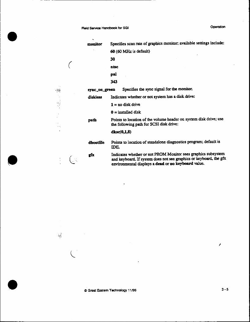
monitor Spemiies scan rate of graphics monitor, available settings include:
60 (60 M H z is default)
30 Utsc
Pd 343
sync-on-gmtn Specifies the sync signal for the monitor.
diskless Indicates whether or not system has a disk drive:
1 = no disk drive
0 = installed disk
Pa* Points to location of the volume header on system disk drive; use the following path for SCSI disk drive:
dLsC(o91a
dboodile Points to location of standalone diagnostics program: default is DE.
gslr Indicates whether or not PROM Monitor sees graphics subsystem and keyboard If system does not see graphics or keyboard the gfx environmental displays a dead or no keyboard value.
i
0 Great Eastern Technology 11/96

Forcing the Console to the Diagnostic Port If you do not have control of the graphics console (monitor may be unreadable or blank and system will not accept commands from keyboard), it may be nuxssary to force the console to the diagnostic port.
To force console output to the diagnostics port:
1. Install an ASCIl terminal to serial port1 of the system. .*.:.; .-.-.. 2. Configure the terminal for 9600 baud, 8 bit 1 stop bit no parity.
3. Power off system and disconnect the keyboard.
4. Power on system.
5. To enter the Command Monitor, from the System Maintenance Menu, enter5
6. To set console environmental to diagnostics, at the Command Monitor prompt,
. .
The system displays the >> prompt.
enter setenv console d.
7. At the Command Monitor prompt, enter init
8 Power off the system a d reconnect the keyboard.
9. Power on system.
The ACSII tem connected to serial port 1 is now the system console. . .
. . .. .. .. .. . .. ..
3-6
c
0 Great Eastern Techndogy 11196

Field Service Handbook far SGI opetauon
._. . t.'. ..
. . . .
Booting the System Manual booting from the PROM Monitor allows you to select the boot device and the boot program. This enables you to boot the system using devices and programs
To boot the system manually, use the boot command in the Command Monitor and the following syntax:
( Merent from the system disk drive and standard boot program.
boot [ - fa] device(x,y, 2) filename [arpumenel
-P
-n
device
.. '. .' . .-: ..
prevents PROM ~ o & t o r from using boot program spec i f ied in boottUe environmental (since default setting for bootfde points to sash, -f option prevents system from loading sash)
Allows system to acccss disk drive, locate boot program and loads it into system memory, but does not execute boot program. Indicates the type of boot device. Possible boot devices include:
dksc SCSI disk drive (includes CD-ROM)
tpsc SCSI tape drive (QIC)
bootp Network - tpqic VME tape drive (QIC)
Specdies controller, device address, and partition
X Selects the controller
Y Selects the device address (SCSI disks star t at drive ID 1)
z . Selects partition where boot program is located
Name of boot 6Ie being loaded by the PROM Monitor. Files include.
sash Standalone shell
fx Disk drive format and exercise utility
ide Integrated Diagnostics Environment
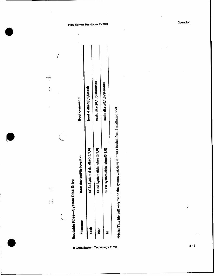
S a table on next page for a list of bootable files and bootable devices.
Q Great Eastem Technology 1 llgs 3-7
;.; 1. ..._ . . -..
. .
- . ._ .-... . . ....’ . . . ..
3-8
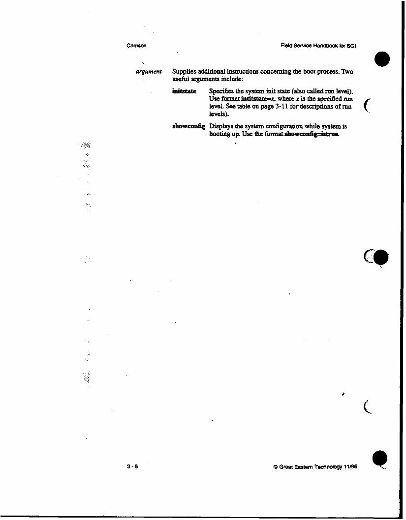
inimate specifies the system init s a t e (also called run level). Use format intimate=r, where x is the spec l f ied run level. See table on page 3-1 1 for descriptions of run ( levels).
showcodg Displays the system configuration while system is booting up. use the formatshoweonfig=istrac
c
I ,”
. .-.-. - -.-.
.. .:
.. . . .. .. +>
Field service Handbook for SGI operation
3-9

ClimsOn
2::::: . . .
. .. . . . .
3-10
f f j
Field Service Handbook br SGI
c
(0 Great Eastern Technology 11196 *. ‘...

::... . . ._ . .
. .
Run Levels
Run bvsl Description
: \ 9 Single user mode
0 System is shut down or in PROM Monitor mode
1 Singleuser mode
2 s his is the normai tun level for multl wer mode
3 Muftiuser mode (with network disa#ed)
4 Alternate run level for multiuser
5 Special run l e v e l for system admin uses
6 System reboot
.. . . ...
3- 11

. . . ..
. .
. .
Standalone Shell (sash) The standalone shell (sash) contains commands used to perfoxm system maintenance.
To boot sash: At the >> prompt. use the following format:
boo+ -f device (x, y, z) filename
Use the bootable file tables on page 3-9 and page 3-10 for the applicable devia, file location, and filename.
If the bootfile environmental points to sash-typically located at dksc(0,1,8) on SCSI drive- the >> promps enter boot.
After you boot sash, the system displays the sash: prompt
sash Commands
Use the help command to display the following sash commands:
boot
cat
COPY
go
help install Is
printeJlv
setarv
ansctenv
version
3- 12
Boots spedied program on wed device; similar to the boot command in the Command Monitor.
Example: boot -f dkrc(O,l,S)fx
Reads a file and displays it on standard output device. Example: cat dk.c ( 0 , 1,6) /rQn/SYSLoQ
Use to copy tiles or file systems; copies block by block
Example: cp dk.~(0,1,1) dk.c(O,l,l)
Executes the listed booted program into memory.
Displays the sash commands and their syntax.
Loads the installation tools. List files and directories in the UNM. file system.
Example: Is dlUc((4&0)/
Displays the PROM Monitor environmental variables and their cumm values. Use to set an envirobtai variable. r
Use to revert a PROM Monitor environmental variable to its previous value. Displays PROM Monitor version and the system’s CPU tupe.
(D Great Eastern T ~ n o l o g y 11/96

Field Service Handbook for SGI Operation
.-.... .. . . ... . ..
- .. . .
. .
. . . . :_.. ...
fx is a formatting and exercise utiIity used for basic maintenance an disk drives.
( Booting fx A variety of ways exist to boot fx.
To boot k from the system disk:
From the Command Monitor prompt (>>). enter the following command for a SCSI system disk drive
boot -f dkSc(0,l~)fx
For any type of disk drive, from the sash prompt, entera
To boot fx from the tape! drive:
If the tape drive is a SCSI device with drive ID 2, at the >> prompt, enter
boot -f fp#a(0#2#0)bc.fP17
If the tape drive is a VME QIC device, at the >> prompt, enter
boot -f ~C(O,O.O)tX-fP17
e .-.: . To boot fk from CD-ROM: 1. To boot sash, from the >> p m p s enter
boot -f dlua(Or6,8)#rrhZP17
2. Tobootfx,atthesash:pmmpt,entex dk88(0#6#7)/.+md/fX.r917
To boot fx &om the nelmork:
Configure a boot server (with aaachcd CD-ROM or tape drive) to provide bootabk files to a client system on the network; configure the client so that it can boot fx over tile network
Notc: Before configuring the boot server, make s u n there is enough disk space in the /usr file system for the /dist/scr file.
. 0 In IRIX 4.05,/dist/sa is 21 MB.
0 In IRM 5.2, /diSt/sa is 28 MB. #
(D Great Eastern Technology 11/96 3 - 13

SGI
.:.:::
.. ::.
On the boot sewer
1. Edit the/usr/erJinirdconffde. At the IRIX system prompt, enter
vi. / u 8 r / a t c / h t d . c d
2. Locate the following line:
t f tp d m udp rrit gurat /u8r/rtc/tftpd tftpa -8 bootputh
3. Edit the above line to so that boopah is /wrhcdhor :
udp d t /tur/.+O/tfw tf- -. /Ort/lMdlboot
4. Save and quit the /wr/etdi i tdconff .
5. Create a directory called/ur/Zmd. At the system prompt. enter
ddir /u8r/local
6. In the /usr/local directory, create a subdirectory called boor (by default. network bootable files must reside in/usrAmal/boot on the boot server). At the prompt, enter
* /u.r/locil/boot
7. Make a directory dd/ur.uZ#oaddkr/dirr. At the system prompt, enter
&dh /U8r/bCd/boot/di8t
8. From a I R E dismbution CD-ROM or tape, copy the/&dsu file (which contains all bootable files) into the/urhc&md& directory. Depending 0x1 the media, do one of the following:
CD-ROM
a. Mount the boot server's CD-ROM on/CDROM. . h Copy the bootable files to/w*&d&t. At the system proms enter
Cp -f /m/diSf/8r /U8r/ ld/boot/di8t
Tape Copy the bootable files to /wzhuhoodiiisr. At the system proms enter
distcp -rrr /dmv/nrtrpr /rur/local/boot/dist .mam
The boot server is now configured so that client systems can boot fx over the network In addition to fx, clients can also boot the stand-alone shell (sash) and the Integrated Diagnostics Environment (DE).
I
3- 14 CD Great Eastern Technorosy 11196

. . .. . ..
Field Service Handbook for SGI Operation
On the client system 1. To ‘set the netaddr environmental (in the PROM Monitor) using the client’s
Internet address* at the >> prompt, enter
8.t- not- ipaddress
2. To set system to ignore installed media device (even if the client has no media device), at the >> prompt, enter
8dZIPI t-hSa 1
3. To a variable that points to’the bootable files in t h e / ~ r ~ c u ~ o o ~ d ~ directoryonthebootserver,atthe>>prompt,enter sot- boo- (1 s e r v e r h o ~ ~ o t /Prt/lwil/boot/&U.t/u
4. To boot fx over the network, at the >> prom* enter boo+ -f $ t e c r ( f ~ . I P l f )
Notc: See the table on page 3-10 for names of other bootable files.
i -
.. ... .. . . ... . .
cD Great Eastern T ~ l o g y 11/98 3- 15
CllmsOn . Reld Service Handbook for SGI
. . ..
. . . . . . . . . . . .. .. . . . .
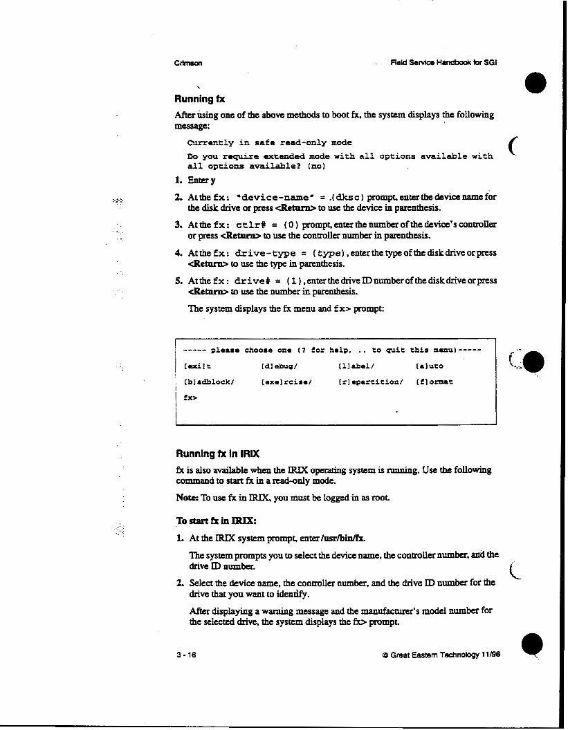
Running fx After king one of tfu: above methods to boot fx. the system displays the following message:
Currently in safe read-only mode Do you require extended mode with all options available with a l l options available? (no)
1. Entery
2. Atthefx: ‘device-name’ = .(dksc) prompsenterthedevicenamefor the disk drive or press < R e m to use the device in parenthesis.
or press <Retarn> to use the controller number in parenthesis. 3. At the f x : c t lr# = ( 0 ) prompt, enter the number of the device’s controller
4. Atthefx: drive-type = ( type) ,enterthetypeofthediskdriveorpress < R e m to use the type in parenthesis.
5. Atthefx: drive# = (l),enterthedriveIDnumberofthediskdriveorpress <Retarn> to use the number in parenthesis.
The system displays the fx menu and f x> prompt:
----- please choose one ( ? f o r help, .. to quit this menu)----- [ d l t [dl ebw/ [I1 d e l / [aluto
[bl adblock/ [exel rcise/ [rlepartition/ [flormat
fx>
Running tx in IRIX fk is also available when the IRM operating system is running. Use the following commaod to star t fx in a read-only mode.
Note: To use fx in IRDC you must be logged in as root.
TostartkinIRIX: 1. At the IRM system promps enter/usr/bidk
The system prompts you to select the device name, the controller number, axid the drive ID number.
2. Select the device name, the controller number, and the drive ID number for the drive that you want to idenw.
After displaying a waxning message and the manufacturer’s model number for the selected drive, the system displays the fx> prompt
3 - 16 Q Great Eastern Technology 11196

Operatton
.:.... . -. . . . .
. .
.... . _ . .. .. . .
fx Commands fx offers the following commands
auto
badblock
ucrcise
Exits Er. During an fx session, a copy of all disk label information is maintained in memory. If you have made changes to the buffer, you have the option to write this information to disk when you exit. fk will ask if you want to re-create the drive label.
Provides capability to rea& write, and dump blocks of data Debug is used primarily for engineering and manufacturing (not needed for field service). Enables you to do various tasks to a disk drive label. You can use label to read the disk's existing label or create a new label using default values.
Note: Labeling the drive destroys existing data and files in the
The label command contains four sub-commands:
show Shows existing contents of disk label. The show command contains a number of sub-commands
volume directory.
sync Writes label in memory b&er to disk.
set Contains sub-commands that allow you to change drive information such as boot information, drive parameters, and partition.
default SGI label, which includes parameters for boot information, drive parameters, and default e t i o n s .
cnates the SGI disk label and formats the disk. Auto is a good choice far fomatting a virgin disk drive. Allows you to access or manipulate the bad block list contained in the disk label on ESDI disk drives. For SCSI drives, you can only display the bad block list
For SCSI disk drives, only the following badblock commands are available:
adbb Add new bad blocks to badblock list in buffer.
showbb Display badblock list from M e r .
Offers a variety of disk exercises. After formatting the disk, use the exercise function to find bad blocks. If a bad block is detected during an exercise, the head and cylinder lowtion of the bad block is entered into the memory buffer. When you exit fk, you have the option to re-creafe the disk label, which will assign an alternative track to a bad block
create Contains sub-commands that allow you to create a
1
Q Great Eastern Technology 11/96 3- 17
\

. - . . . :... ..
. _.. ..
crimson Field Senrice H~dboolc for SGI
The exercise commands perform the following functions:
butterfly Performs buttcrfiy exercise
errfog Print error log random Performs random seek exercise
sequential Performs sequential test
stoponerror Set to stop exercise when error occurs
sttttstpat Sets test pattern for ex-
showtestpat Prints data test pattern
complete Performs complete reacUwrite test
repartition Use to repartition a disk drive. The following sub-commands are available:
rootdrive Use to repartition a drive that will be used as the root (system) drive.
optiondrive Use to repartition a second disk drive (one that wil l not be used as the root drive).
nsize Use to repartition a partition on a disk drive. When
f
apvt Use to manually set partition sizes and types. k....
No- Repartitioning the drive can destroy data.
format Formats the disk drive. Use to format the entire drive or sections of the drive. Formatting the disk drive destroys any existing data that resides in the volume header of the disk label (such as sash, fx. and IDE).
.. . :. .. ._ . . . .
3- 18 Q Great Eastern Technology 11/96

I--
Operation Field Service Handbook for SGI
Formatting and Labeling a System Disk Drive
To format the disk drive:
1. Boot fx (see page 3-13 for procedures for booting fx).
2. At the extended mode prompt, enter y.
3. At the device name, controller #, and drive # prompts, select the appropriate
4. To select the format commaud from the fx main menu, at the fx> prompt, enterf.
ValUeS.
The system will prompt you for which drive parameters to use. No& When formatting an unformatted drive, use the default drive parameters.
5. To select the current (default) parameters, press cRetarn>. The system displays the prompt, "about to destroy da&..ok?"
6. To format the disk drive, at the "...ok" prompt, enteryes.
The system formats the disk drive. When formatting is complete, system returns to fx main menu. After formatting, label the disk drive.
To Iabel the disk drive:
1. From e fx main menu, at the fx> prompt, enterL
2. To crcate a label, at the Mabel prompt, e n m c
3. To create a complete label, at the WlabeYcreate prompt, entera
The system czc8tes the new label.
4. To go back up to the label menu, at the fx/labeYcreate prompt, type.. and pnss
5. To write (sync) the new label to the volume header of the disk drive, at the Mabel> prompt, enter sy. The system writes the label to the disk drive and displays the message,
<Rctarn>.
w r i n g label info to dksc(O.1, )"
6. To exit fs at the fxhbeb prompt, enter Jexit.
. The system returns to the System Maintenance Menu.
(D Great Eastern Technology 11196 3- 19

::x: . . .
. .. . . . .
..
. ... ..
CrlmsOn Field Senrlce Handbook for SGI
Formatting, Labeling, and Repartitioning a Second Disk Drive
To format the disk drive:
1. Boot fx (see page 3-13 for procedures for booting fx).
2. At the extended mode prompt, enter y.
3. At each of the device name and controller # prompts, select the appropriate value.
4. At the drive# pmmpt, enter the appropriate drive ID. (Drive ID 1 is reserved for
5. To select the format commaad dtom the fx main menu. at the fb prompt, enterf.
system disk drive).
The system will prompt you for which drive parameters to use. Note: When formatting an unformatted drive, use the default drive parameters.
6. To select the current (default) parameters, press d e - .
The system displays the prompt, "about to desmy dam..okT'
7. To format the disk drive, at the "...ok" prompt, enter yes.
The system formats the disk drive. When format is complete, system rem to fx main menu.
To label and repartition the disk drive:
1. Fmm the fx main menu, at the fx> prompt, enterl.
2. Tocreateala&l,attheSdlabelprompt,enterc 3. To cnate a complete label. at the GdlabeUcrcate ptonzps mtera
The system creates the new label.
4. Togobackuptothemainmenu,atthefxflabeYQeaceprompt,type~"andpress
5. To repartition the drive, at the fx> prompt, enter r.
< R e m .
The system displays the current partition table and the repartition menu.
fx/reparrition prompt, enter 0.
System displays message warning that existing data will be lost when drive is rcpanitioncd.
6. To reparcition the drive as an option drive (non-system drive), at the
I
7. To repartition the disk (and lose existing data), at the Continue? prompt, entery.
System repartitions disk label, writes the label to the volume header, and displays the new partition table. .
8. To exit fx, at the Mabel> prompc enter ../exit.
The system returns to the System Maintenance Menu.
3-20 (0 Great Eastm Technology 11/96

flekl Senrice Handbook for SGI OpemtJon
Exercising a Disk Drive
1. Boot fx (see page 3-13 for procedures for booting fx).
2. At the extended mode prompt, enter y.
3. At the device name, controller #, and drive #, select the appropriate value.
4. To select the exercise command. from the fx> prompt, enter exe.
The system displays the acrcise subcommands.
Furxr
----- please choose one ( 1 €or help, .. to quit this menu)----- [bl utterfly [rl andom [st] op-on-error [shlowtestpat
[el rrorlog [sepluential [slettestpat tcl~m~lete
fx/exerciaar
5. To run a test, at the Wexercisc prompf enter the command for the test you want to run (See page 3-18 for a description of the exercise tesu). When the test is selected the system will prompt you for a modifier (default modifier is read only). The available modifiers are
[rd]-only: Read only: a readdata command will check for readcomplete.
[rol-cmp: Read and compare: system compares two disk read commands.
[SI& Seek; performs a seek and read command to every disk block. (This
c: .._ .
test takes a long time to complete.)
[w~olnly: Write only: write command looks for a write complete.
[wwfmp: Write compare; write command foUowed by a rcad and compare.
. .
. . -.. ..x
6. To select a modifier, at the prompt, enter the command for the modifier.
The system runs the test Note that the system ignores the badblock list 7. To display the error log after the test is complete, at the fx/exercise> prompt,
8. To exit fx, at the fx/exmise> prompt, enter Jexk
e n t a e.
The system rem to the System Maintenance Menu c
Q Great Eastern Technology 11/96 3 - 21

.:.:.:. . . . . .
. ...
. .
Adding to the Bad Block List Iffxdiscovenabadblockonadiskdriveduringanexercise,youcanusefxtoadd the block to the disk's bad block list.
Toaddabadblocktothebadblocklist
1. Boot fx. See page 3-13 for the procedures for booting fx. 2. At the extended mode pmmpf enter y.
3. At the device name, conaroller #, and drive #, select the appropriate values.
4. To select the bad block command, at the fx> prompt. enter b.
5. To select the addbb (add new badblock to badblock list) command, at the fx/badblocb prompt. enter a
The system prompts you for a bad block number:
please enter a bn from 0 to xcuzxx fx/badblock/addbb: add badblock:
6. At the add badblock: prompt. enter the bad block number.
After you enter the bad block number, fx attempts to save the data. The system then redisplays the add badblock prompt
7. Repeat step 6 to add additional bad blocks.
8. When finished adding bad blocks, exit the addbb utility. At the add badblock: prompk type .. and press <Retarn>. The system displays the Wbadblock prompt
9. To exit fs at the fx/badbl& prpmps enter Jesit. *
The system returns to the System Mainenaace Menu.
f
c
3-22

Field Service Handbook for SGI Opemuon
.-.:.: . .. . .
-.-.
Identifying Disk Drives Use the fx utility ( h m the PROM Monitor or from IRIX) to identify the mauufacturcr and manufactum’s model number of the disk drive(S) installed in the system.
To identify a disk drive
1. Boot fx. See page 3-13 for the procedures for booting fx. Nde: If you boot fx fiom the PFOM Monitor, the system ask if you warit to run fx in an extended mode (write mode).
2. If the system displays an extended mode promps entern.
3. At the device name, controller #, and drive #, select the appropriate values.
4. At the fb prompt, enter labeYshow/all.
The system displays detailed information about the disk drive.
5. To exit fx, at the fb prompt, enter exit
.. .. .. - ..: i
cD Great Eastern Techndogy 11/96 3-23

:...:. . .-
. .
. .
. .
.. ..
Integrated Diagnostics Environment (IDE) The Integrated Diagnostics Envkmmat @E) for SGI systems is comprised of a set of manu€acturing tests that field service personnel can use to troubleshoot hardware problems to the FRU level.
IDE can be run h m either the graphics console or the diagnostic console.
Running IDE The IDE tests can be run in two ways:
From the System Maiaknana Menu
1. Select 3.
The system prompts you for the location (media device) of D E .
2. Select the appropriate media device.
The system displays the DUGS: prompt
From bootable media
To boot IDE from the CD-ROM drive, from the sash: promps enter
dkrc(0,6,7)/8tmd/i&.IOl’l
When IDE is booted, the system displays the DIAGS: prompt
To boot IDE from a tape drive (drive ID Z), from the >> prompt, enter
boot -f tp8c(O,l,O)i&.IP17
Note If the tape drive is codgured as drive ID 7. use tpsc(0,7,0)id~17 to boot IDE.
When IDE is booted, the system displays the DIAGS: prompt
(::a c. .. -
To boot IDE from the system disk (with DUX and IDE installed), at the sash: Proms en= /8+rrrd/i&
To interrupt these tests, type 4M-o and then <Retarn>. The system displays the DIAGS: prompt.
Note: IDE is not installed by default It must be copied into the/stru2d &tory from the installation media.
When you run DE, it automatically performs the processor and the graphic subsystem tests.
3 - 24

..
. .. - .. .. .. . .
Field Service Handbook for SGI Operation
IDE Commands
To display a list of available IDE commands, at the DUGS: prompt, enter help. The system displays the following commands:
help: ? Displays the list of IDE tests and options
auto: a Executes all the tests setup in the test table.
hardware: c (The hardware configuration command is no longer supported.)
dump: d Dumps the address mapping of the SCSI and VME buses.
flags: f Use to configure a test. With these flags you can pick the processor to run diagnostics on, designate the amount of memory tested, change the reporting level, select the tests to be run, and select the YO devices to be tested.
See the next page for a description about using flags to configure D E tests.
init: i Sets the logfile to all zeros. logfile: 1 Prints the logfile to the display.
menu: m the available tests or subtests. When used without an argument, the menu command lists the available test groups. The command m restgroup displays a list of the subtests within restgmup. Each subtest is designed to test a specific area of logic on a board or device. Subtests can be run individually or as a P U P -
IDE %st groups:
cpa CPU tests; includes data cache tests bus Backplane bus tests; called SYNC bus tests
memory M e m g r wts; includes sockets, addressing, data
Path Test the ability to dw&e to the cache using all e*
io Tests the YO board, SCSI buses, and VME bus
ma Floating point unit tests
quik q Quits D E . execute: x Executes an IDE test; also use to loop a test multiple times. ,
Q Great Eastern Technology 11/96 3-25

-:: .. ..
.. . . . .
~ .. . . .. ._....
System Configuration Rags
0 Selecting tests to be run f
Selecting amount of memory to be tested
Selecting YO devices to be tested . Changing the repOmng level
Each flag can be set to different states, which define parameters for D E tests.
Displaying IDE Flags
To display a list of the available flags and their current states
At the DIAGS: promps enter f.
The system displays each flag and the current state to which flag is set:
m: memory testing area: from Ox400000 to Ox37ffffc b: Block Mode is on r: m o t e log file is on e: current e r r o r mode is 1 which is continue after error occurs v: Verbose Mode k: Disk Write Mode is off (no tests will write to disks) w: Warning Message Mode is on a: current auto execution table is LONG table d: m e devices for io test are ipi(O,O,l) t: scsi devices for io test are dksc (0,1,1) i: vme devices-for mp test are ipi(O,O,l) ipi(l,O,l) c: scsi devices f o r mp test are dksc(O.l.1) dksc(l,l,l) p: Parity and ECC exceptions enabled
To display possible states for a
At the DIAGS: proms enter
f flagname ?
System displays possible flag statcs and descriptions for specrfied flag.
To change a tlag state:
At the DIAGS: promps enter
f flagname flagstate
t
L
3-26 (D Great Eastern Technology 11/96

Field Servla, Handbook for SGI Operation
IDE Flags m ’ Memory: use to setup the area of memory to be tested. Note that
IDE resides in the fmt four M B s of memory. In older versions of IDE the default setting tests 12 MB of memory.
Example: f m 80oooO:8flotITc (c
b Block mode; sets up the type of YO transfer used during a test Can be set to on (“1,’) or off (“0‘9. For testing disk drives, set to oa
Example: f b 1
r Remote; when set to “on”. the logging information is Sent to serial Port 2 (ttyW
Example: f r 1
e Error mode; available error modes include continued after error, stop on emr. or loop on error (used for bench testing).
Example: f e 2
v Verbose; used to enable (1) or disable (0) information messages. When enabled, system displays all information messages; when disabled, only error messages are displayed.
k-; Example: f v 0
k Enable writes to the YO devices. By default, this flag is set to off or 0 to protect customer data Before enabling disk writes, you should check the c, d i and t flags. By default these Bags should point to
Note: Before enabling the k flag and running the test determine
the swap partition.
the location of the swap partition.
Example: fk 1
W Warning; default setting displays all warning and error messages. If disabled, system does not display warning or mor messages.
Example: fk 1 .;.:. . .,.
a ~u tomat i ca ly a suite of tests. These tests range from an individual board tests to overnight tests. For field service, use the field engineering tests. To display of list of possible test suites, at the DUGS: prompf enter f a ?.
CD Great Eastern Technology 1 1196

._. .:.:. . .. ..
. . .. .. . .
t
i
CrlmsOn . Field Secvlce Handbook br SGI
.d VME drives; selects the VME YO device to be tested. By default, the P I controller 0, device 0, partition 1 (swap) is selected.
Examples:
f d ipi(O,O,l)-PI devices
f d xyl(O,O,l>sMD devices
f d dkip(O,O,l)-ESDI devices
f d tpqic(O,O,l)-QIC @PC devices
SCSI drives; selects the SCSI UO device to be tested. By default, the SCSI conaoller 0, device 1. partition 1 (swap) is selemd.
Examples:
f t dksc(O, l , l~CSI disk f t tpsc(oJ,o>scsI tape
Selects the VME YO devices to be tested bymp tests (must spedy two devices). By default the P I controller 0, device 0, partition 1 (swap). and the P I controller 1, device 0, partition 1 (swap) are selected to be tested.
Examples:
. . . . . . . . . . ..
C
P
3-28
i d ipi(0,OJ) ipi(l,O,l)
i d XyW,W) x y w u )
i d dkip(O,O,l) dkip(l,O,l) i d tpqic(0,OJ) dJdp(O,O,l)
Selects the SCSI YO devices to be tested by mp tests (must speafy two devices). By default the SCSI controller 0, device 1, partition 1 (swap) and controller 1, device 1, partition 1 (swap) are selected. Examples:
f c dlrSc(0JJ) dLsC(1JJ)
f c tPse(O,l,O) dksC(O,lJ)
Disables parity and ECC exceptions logic; allows bench technicians to look at memory ermrs without diagnostics stopping on enors. Not recommended for field use.
(0 Great Eastern Techrology 11/96

FhM Senrlce Handbook for SGI operation
.. . .
Using IDE to Test the System The following procedure illustrates how to configure and execute a comprehensive IDE diagnostic.
i 1. Boot DE. See page 3-24 for information about booting DE.
2. Set the error t e s t flag (e) to stop on the first error. At the DIAGS: prompt, enter
f r 2
3. Set the flag s t a t e s for VME VO device (d) and VME VO device for MP tests 0) to perform writes to the appropriate VME disk
a. Designate the d flag state for appropriate VME device: ESD1,disk controller
SMD disk controller
DIAGS:f d =l(O,O,l)
or DIAGS:f i dkb(0,Orl) dUP(l,Orl)
4. Set the flag states for SCSI VO device (t) and SCSI YO device for mp tests (c) to perform writes to the appmpriate SCSI device. a. Designate the t flag state for appmpriate SCSI device:
DIAGS:f t dk8a(O,t.i)
Examples: I
Q Great Eastern Technology 11/96
.:.:. ... . . . . .
. . . .
. .
CrlltlSUl Reld Sefvka H~dboolc br Sol
5. Enable the write mode for testing disk and tape drives. At the DIAGS: prompt,
f k l
Note: Write mode writes to disk only if you have configured the d, i t, and c flag states to write to the swap partition. Data will be destroyed if the swap space on the designated device is not specified.
6. Set the a flag to run the FE tests. At the DIAGS: prompt enter
f a 7
7. Configure D E to display on the sys&m console. At the DIAGS: prompt, enter
f 8 1
8. Start system tests. At the DIAGS: prompt, enter a
"he system displays the following warning:
Warning: Disk Write Mode is ON (some tests will write to disk partition 1) . If you don't want to run these tests, please use 'f k 0' to turn the Disk Write Mode o f f . Continue? (y/ [n] )
9. At this point, you have two options:
a. If you are uncerrain of the location of any of the swap partitions or haw not setthed,it,andchgstates,entern. Do the following:
1. To disable the disk write flag, at the DIAGS: promps enterf k 0.
2. To start the system test, enter a
b If you have setup the 4 i t, and c flags to point to the swap partitions, enter
As the tests run, the system displays messages. If all tests run without an enro~, the system displays a message saying tests have passed.
If a rest faiia the system will stop 011 that error. Set the Troubleshooting (Section 4) for help determiaing the next course of action.
y continue the t e s ~
.. .. :.- .. .. .. . .
3-30 (D Great Eastern Technology 11/96
.. ..
Field Service Handbook for SGI Operation
Running IDETest Groups or Subtests
To run an IDE test p u p :
/ At the DUGS: prompt, enter I
x testgroup
when testgmup is the name of the test group (see the menu command on page 3-25 for a list of test groups).
To run an IDE subtest: At the DIAGS: prompt, enter
x subtest
where subrest is the name of a subtest within a test group
' See the menu command on page 3-25 for a list of test groups. To displays a list of subtests for a test group, at the DIAGS: prompt, enterm testgroup.
To loop a test or subtest: At the DUGS: prompt, enter
x test*n
:. .-: ., whae n equals the number of times to loop test.
Q Great Eastern Technology 1 1 /96 3 - 31

Field Service Handbook kr SGI
Rebuilding the Kernel If the system does not boot or if the booting process hangs, the problim may be caused by a cormpted kernel. Use the following procedure as a quick way to rebuild the kernel.
To =build the kern&
1. Enter the Installation utility. At the System Maintenance Menu, enterb
System prompts you to select a media device and to install media.
2 InsM appropriate media into the selected media device. 3. Start the Administrative Command utility. At the Inso prompt, enteradmin.
4. Start a UNIX shell. At the prompt, enter sh.
5. Change to the /root directory. At the # prompt, enter cd mot
Note: When in’the shell in the Administrative command utility, the/mot directory is the /directory when the system has booted and is running IRIX.
6. Rename the kernel. At the # prompt, enter mv unix unix.copy.
7. Exit the shell. At the # prompt, enter exit
8. Exit the Administrative Command utility. At the arlmin> prompt, enterexit
The system executes the exit commands and displays various messages.
9. Restart t&e system. At the “Ready to restart the system. Restart?“ prompt, entery.
Restarting the system causes a new kernel to be built The system uses the new kernel to boot
. . .. _. . ..
3 - 3 2

.-...-. . . ._ .. . . ..
Testing Power Supply Voltages
Operalion
Use a digital voltage meter (DVM) and the voltage test points on the system backplane to test power supply voltages far Crimson system. Replace power
For testing voltages. ut the following pin-out and orientation for the 12-pin Mol= connector at location J4 oa the system backplane (see page 2-8).
Warning: System produce a large current potential, which may be hazardous. Only trained service persomel should test power supply voltages.
(* - supply if voltages are not within tolerances.
voltage Pin Tolerance
* 1 4- 0.1 sv -52V 6 4- 0 .19
+12v 3 4- 0.6v
-1 2v 4 4- 0.6V
GND 2.57, or 0 N/A
3-33

.. . . . .
To test the voltages on Crimson systems:
1. Shut down the operating system.
2. Turn off .the power to the system.
3. Turn off the power circuit breaker, located on the back of the system.
4. On the system tower, remove the back cover panel and metal plate that covers the system backplane.
5. Locare the 12-pin Molex connector at location J4, near the bottom of the backplane (see Section 2, page 2-8 for component locations)
6. Locate the GND bus bar (top bus bar, covered with blue insulation) connections at locations J11 and J13 and the +5V bus bar (bottom bus bar) connections at locations J10 and J12.
7. Turn on the power circuit breaker.
8. Power-on the system.
9. Attach the DVM ground lead to the GND bus bar connections, l d o n s J11 or J13, or to pin 8 of the connector at location J4 (both are ground points for the power supply).
laTo test the +5V, attach the DVM hot lead to +5V bus bar.
The voltage should be +5V 4-. 15 V. 1LTo test the +l2V, attach the DVM hot lead to pin 3 of the connector at location J3.
The voltage should read +12V +/-.6V.
=To test the -53 V, attach the DVM hot lead to pin 6 of the connector at location J3.
The voltage should read -5.2 volts 4-.1SV.
U T 0 test the -UV, attach the DVM hot lead to pin 4 of the connector at location J3.
The voltage should read -12 volts 4-.6V.
lAWhcn finished testing the voltages, turn off the power to the system.
l!j.If necessary, replace power supply.
3-34
1
@ Great Eastern Technology 11196

Section 4-Troubleshooting This section contains the following flow charts for isolating failing 'field replaceable
(- units (FRUs) on Crimson systems.
System power problems
Graphics problems
System fault during poweran
IRXX boot problems
Hang or panic errors
Intermittent errors
Undetermined problems
. . . . . .
. . . .. .. ... .. .. . .
i
0 Great Eastern Technology 1 1 /96 4 - 1

-..2. . .. ..
. ..
CllmsoCr
. Master Troubleshooting Flow Chart
Reld Service Handbook lor SGI
Depending on the specific type of emr. the master flow chart will point to the appropriate flow chart and page number.
I A
I
1"
4 - 2 (0 Great Eastern Technology 11/96

fleld Setvice Handbook for SGI Troubleshooting
Flow Chart A-System Power Problems
: .:.:; . . ._ ...
.. .:
Q
I
..-.. . .. . . . .
0 Great Eastern Technology 11196 4 - 3

Crimson
. . . .:: .. . .
Flow Chart Al-Over Heating Problems
L I I
.-.-. .. ..
i
4 - 4 (0 Great Eastern Technology 11 /96 0
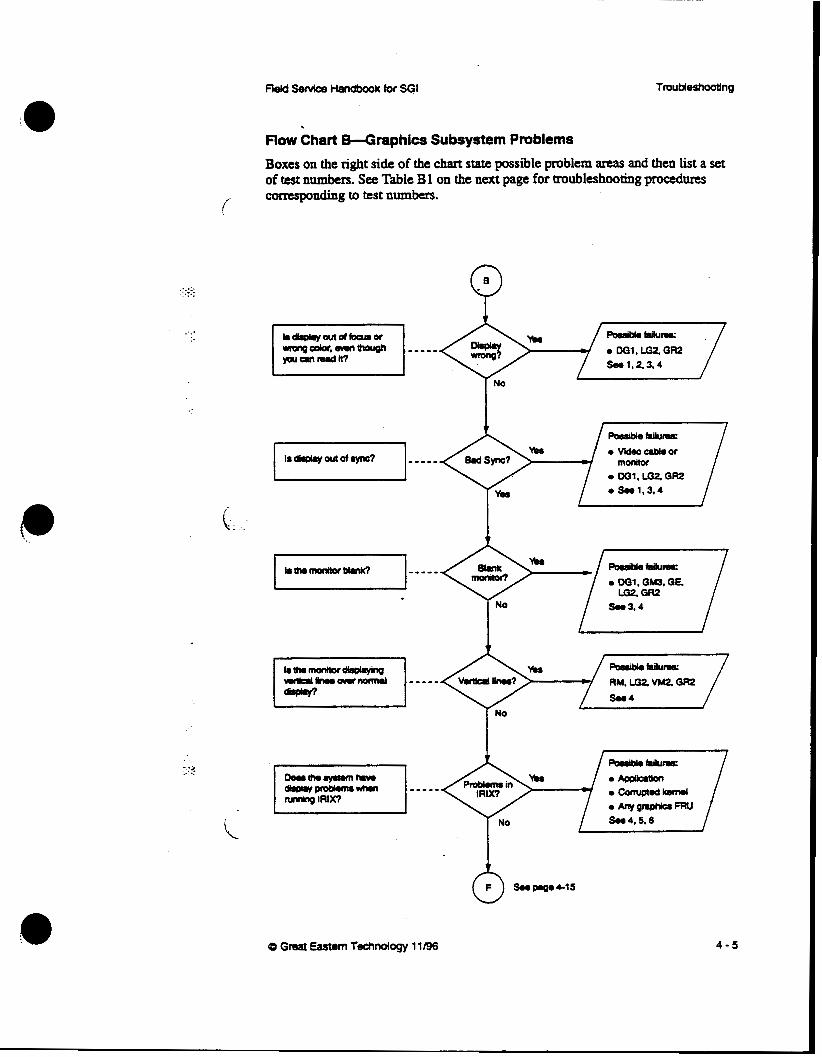
TmuMeshooUng
:.-.. . ._. . . ...
. . . .
- :j . .. ..
Flow Chart &-Graphics Subsystem Problems
Boxes on the right si& of the chart state possible problem areas and then list a set of test numbers. See Table B 1 on the next page for troubleshooting procedures camsponding to test numbers.
(
I No
0 Great Eastern Technology 11/96 4 - 5

.:.:.: . ..
Table B1-Troubleshooting Graphics Subsystems Problems
Test Procedum Possible Failing FRU
Check monitor cables
Replace cables 1 Rotate the RGB cables cables
2 Check monitor termination, last device in video Operator error; chain must be terminated bad termination
3 Check monitor Attach known-good monitor to system
Monitor
4
~ ~
1. If graphics console is not functioning, force the console to the diagnostics port (See Section 3, page 3-6)
2 On VGXT subsystems, connect the ASCII Any board in terminal to the diagnostics port on the GM3 graphics and power cyde the system. Look for subsystem graphics POST failures.
for normal LED patterns. 3. Check Graphics boards LEDs. See W o n 2
5 Run the graphics demos or customeh Graphics or application CPU board
e
Bad file system
4 - 6 CD Great Eastern Technology 11/96

Flow Chart C--POST Fails Boxes 'm the right side of the chart s t a t e possible failing FRUs and point you to additional troubleshooting procedms. See Table C1 on the next page for a list of POST failure messages corresponding to failed FRUs.
(
t.
. ... .. . . .-. . .
I I I
4 - 7

.:::.:
..:
Table Cl-System Fails POSTS
When a failure occurs during the POSTS, the system displays Mor information on the graphic console and an A S U I terminal connected to the diagnostics port ( ser ia l port 1); system displays error message indicating the test that failed.
See the table below for decoding the diagnostic messages.
POST Message Failing FRU
Memory address test ’ Group 1 SIMMs, CPU board
Slzing Caches test failed CW, 1038. Group 1 Sl”s
UART test failed ~~
CPU board
Timerklock test failed CPU board
Floating point unit test failed CPU board
Sync bus controller test failed CPU board
VO mapper, INT vectors test failed CPU, 1038 board
. .
SCSl controller test failed 1038 board
System bus test failed CPU, 1038, or backplane
caches test falled C W board
-_
Full memory test failed SIMMs, CPU board
Memorysizewom SIMMs, CPU board
. ’. .: ... . ..
t
4 - a
t
Q Great Eastern Technology 11/96
. . :.
. . ....-. . .
Reld senrice Handbook far SGI TmuMeshooEing
By-Passing the POSTS
If the System hangs during the POST, the mode switches located on the status panel board can be set to bypass the POSTS. After bypassing the POSTS; run DDE to isolate the cause of the failing POST (see Section 3, page 3-24). r- To by-pass the POSTS: 1. Locate the mode DIP switches on PS3 status panel (see Section 2, page 2-10)
2 Set switches 3 and 8 to the “OFF‘ position. 3. Power cycle or reset the system.
The system will by-pass the P O S T S and display the System Maintenance menu.
0 Great Eastern Technology 11/96 4 - 9
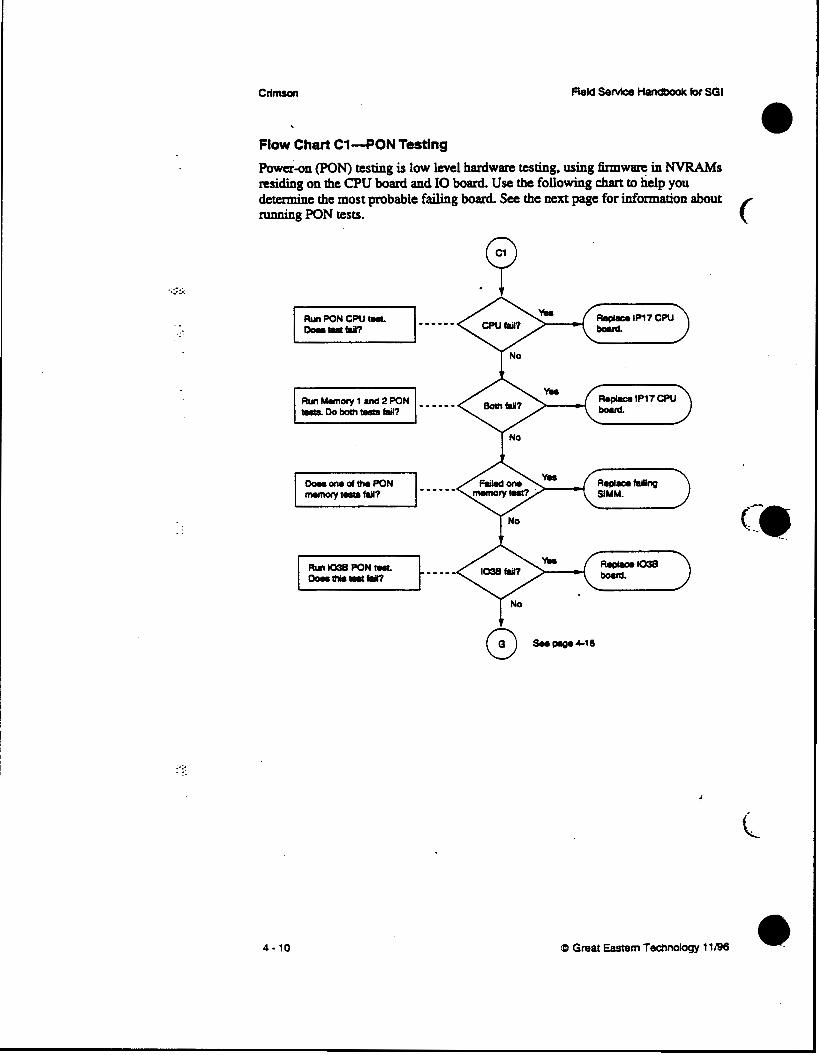
CllmsOn Field Service Handbook for SGI
Flow Chart Cl-PON Testing
Pow&-on ON) testing is low level hardware testing, using firmw- in N V R A M s residing on the CPU board and 10 board. Use the following chart to help you detcnnine the most probable failing board. See the next page for information about running PON tests.
4 - 10
I No
c
Q Great Eastern Technology 11/96 a
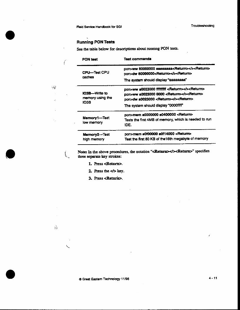
%Id Selvlce Handbook for SGI
Running PON Tests
See the table below far descriptions about running PON tests. PON test
i Test commands
CPU-Test CPU pon>w 8OOOOOOO aaaaaaaacRetum>tl><Rehrnr>
caches pon>dw m - W R m r n
The system should display %aaaaaa=
. . .. .,. . . a pon>w a0023000 WWff <Return&Return> lO3B-write to p o m w aOO23OOO oo00 *RetumxhReturn> memory using the 1038
pon>dw aOO23OOO <Raurn*c/KRetum>
The system should display ”OOOOfW
pon>mem aOoooOOO a0400000 <Return> Tests the first 4MB of memory, which is needed to run IDE.
Memoryl-Test ’ lowmemory
~~ ~
Memory2-Test pon>mem aOMOOOO aOfl4000 <Return, high memory Test the first 80 KB of thel6th megabyte of memory
N o k In the above procedures, the notation “cRetsuw4xRetarw” specifies \..- three sepanue key strokes:
1. Press <Retarn>.
. . .. .. . . .. ..
0 Great Eastern Technology 11196
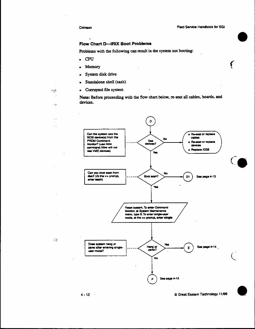
c f i m
. .
. .. . . . . . .. ..
Flow Chart D-IRIX Boot Problems
Problems with the following can result in the system not booring:
c
4 - 12 11/96

.._-.. . .. . .. . .
. .
ReM Senrice Handbook for SGI Troubleshooting
Flow Chart Dl-System Cannot Boot sash From System Disk
. .. ::. ..
Cb Great Eastern Technology 1 1/96 4 - 13

CrlmsOn
...-. . ._ . .
. ._
. .
-.-
Flow Chart E-System Hangs or Panics
Use chart to troubleshoot a system that will not boot single or multi-uscr IRIX.
Q
4 - 14

Troubleshooting
f
e . . .
t .
Field Sewice Handbook for SGI
Flow Chart Wntermittent Problems
:.-. ..-... . .
4 - 15
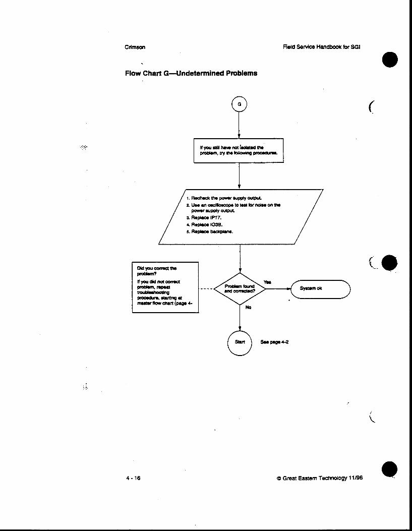
Crlmson
Flow Chart G-Undetermined Problems
4 - 16
1 1 I A
Q Great Eastern Technology 11196 e

. :::: . .
Section 5-Field Replaceable Units This section contains a list of field replaceable units (FRUs) for Crimson systems.
.. Also included is a description of SGI's part numbaing nomenclature.
Part Number Nomenclature
I (. . : . .
.. --. . . ..
SGI's part numbers identify four types of basic system components.
0 printed circuit assemblies (PCAS)
0 Peripheral devices (usually third-party)
Assemblies
Cable Assemblies
Printed Circuit Assemblies
Part numbers for printed circuit assemblies (PC&) such as CPU boards (without daughter cards), daughter cards, YO boards, memory boards. graphic subsystem components, and SI[" modules or other basic circuit board take the following format
030-xxxx-xxx
For basic PCAs, the fust three digits are "030." The second four digits are unique to the particular part and rarely change. The last three digits usually denote options or revision levels and will change during the part's life cycle.
0 Great Eastern Technology 11/96 5 - 1

CrlmsOn ' field Senrice Handbook for SGI
Peripheral Devices %pheral devices such as raw disk drives (without brackets or sled), tape drives, CD-ROM drives, power supplies, and monitors purchased by SGI and then configured into systems are identified by a sevendigit number beginning with "9".
9 xxxxxx
This sevendigit number is different from the manufacturer's part number.
Assemblies
PCAs or peripheral devices configured together or configured with additional parts such as mounting brackets or cables are called assemblies ("ASSY" in part descriptions). Assemblies are identified by a part number that is completely different from the individual PCAs or peripheral devices that comprise an assembly.
Part numbers for assemblies take the following format:
0 1 3-xxxx-xxx
. .
. . _.
An assembly part number is similar to a PCA part number except that the first three digits are "013". b m b l i e s include CPU boards with daughter cards, entire graphics subsystems, and disk and tape drives with sleds and cables.
Cable Assemblies I
Part numbers for cable assemblies such as power harnesses, video cables, and SCSI cables begin with "018".
5 - 2 CD Great Eastern Technology 11/96

\ -
. . . .. . .. .. . . . .
fleM Service Handbook for SGI
FRU List-Crimson
(.
CPlJ-Memory-40
FRU Number Description
Field Replaceable Units
030-0222-00x PCA 1038 VO CONTROLLER
030-0236-OOx PCA iP17 100 MHZ R 4 0 0 0 CPU
030-051 2-OOx PCA IP17 150 MHZ R 4 4 0 0 CPU
030-0133-001 PCA SM1 SlMM 2M8 80NS
030-0184-002 PCA SM2 SlMM 8MB 80NS
(D Great Eastem Technology 11/98 5 - 3
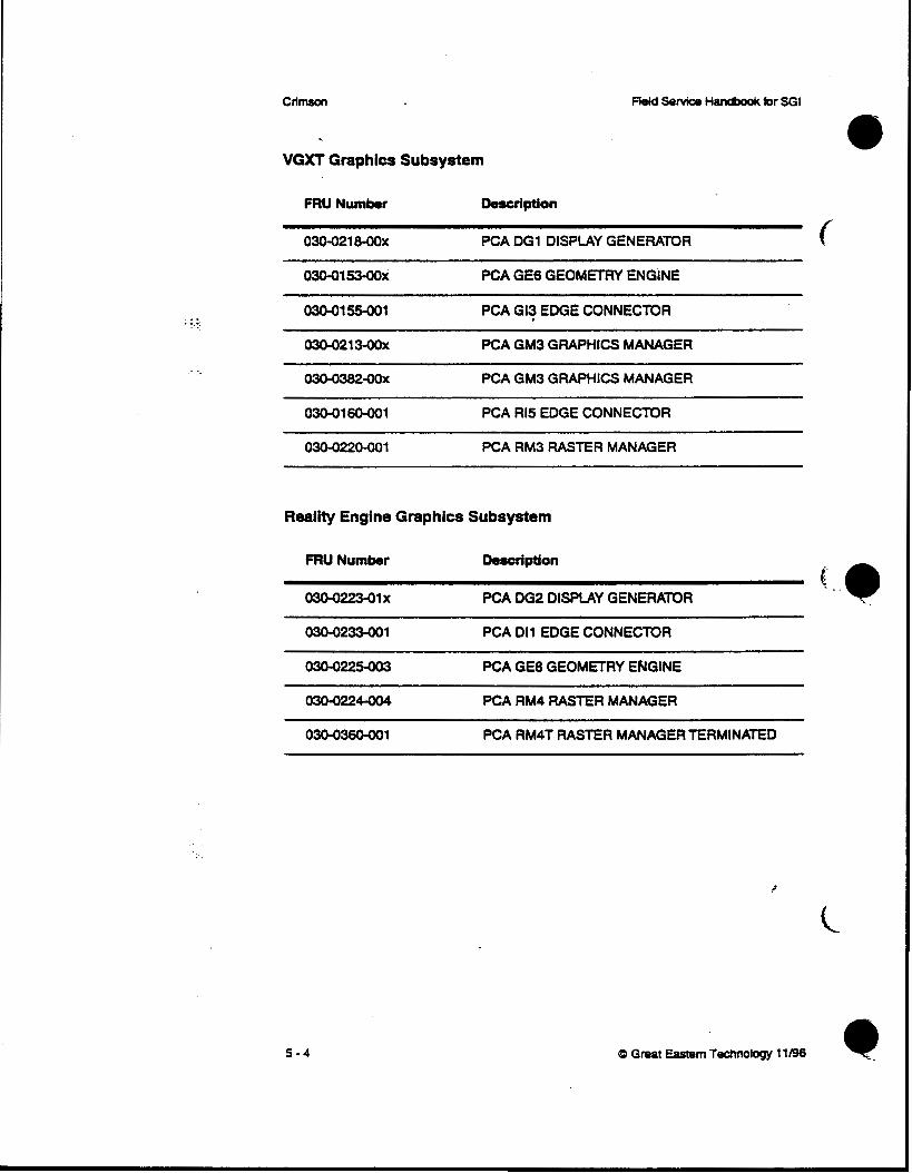
. ... : .. . .
ClimsaCr FieM Senrice Handbook for SGI
VGXT Graphics Subsystem
FRU Number Description
030-021 8-00~ PCA DG1 DISPLAY GENERATOR
03Mll53-oOx PCA GE6 GEOMETRY ENGINE
o3O-0155-001 PCA GI3 EDGE CONNECTOR
PCA GM3 GRAPHICS MANAGER
030-0382-00X PCA GM3 GRAPHICS MANAGER
030-016o-001 PCA R15 EDGE CONNECTOR
PCA RM3 RASTER MANAGER
Realtty Engine Graphics Subsystem
FRU Number Description
o30-022341 x PCA 062 DISPLAY GENERATOR g.
PCA Dl1 EDGE CONNECTOR
030-0225-003 PCA GE8 GEOMETRY ENGINE
030-0224-004 PCA RM4 RASTER MANAGER
030-036o-O01 PCA RM4T RASTER MANAGER TERMINATED
~~~~ ~~~~~ ~~ ~~~
5 - 4 CP Great Eastern Technology 11/96

Field Reolaceable Units
Single-Board Graphics Subsystems
FRU Number Description
( ' 01 3-0493-oox PCA ASSY BASIC LEVEL GRAPHICS
01 3-o496-oox PCA ASSY XS24 GRAPHICS
01 3-o49eoox PCA ASSY ELAN GRAPHICS
013-067o-oo1 PCA ASSY EXTF4EME
030-0248-003 PCA MG1 ADAPTER
030-81 17-001 PCA GR2 w/ 1GRs GRAPHICS MOTHERBOARD
030-8058-006 PCA GR2 w/ 4GRs GRAPHICS MOTHERBOARD
03081 1 2 m PCA IN1 GAULEO VIDEO
o30-8094M)X PCA LG2X2 DUAL-HEAD BASIC LEVEL
03Q8095M)x PCA SRV1 INDIGO VIDEO
030g093QOx PCA VBl.l VIDEO BOARD
030605400x PCA VM2 VIDEO MEMORY MODULE
030-81 05-004 PCA VB2 VIDEO BOARD
030g060M)x PCA ZB4 2-BUFFER CARD
030-81o6-oo4 PCA GU1 GRAPHIC BOARD
030-81 07-002 PCARU1 RASTERBOARD
(0 Great Eastern Technology 1 1 M 5 - 5
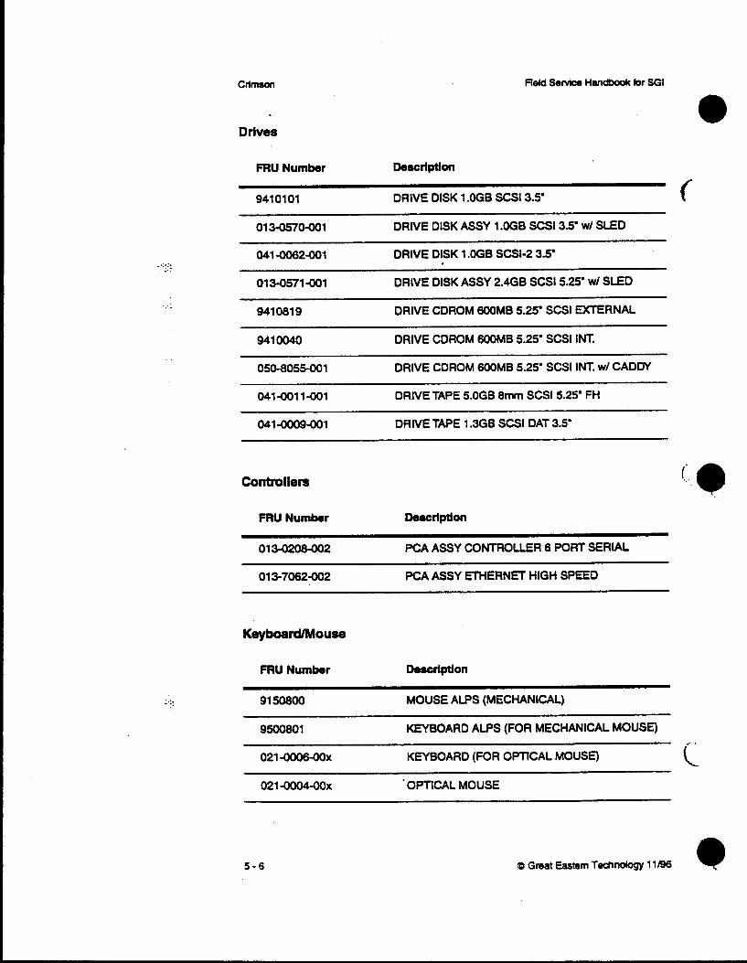
crlmson
Drives
.. . .. . . . .. . -
. . ..
- 0 .
. .
. . ..
FRU Number [k.cription
941 01 01 DRIVE DISK 1 .OGB SCS13.5’
01 3-0570-001 DRIVE DISK ASSY 1 .OGB SCSl3.5’ wl SLED
041-0062-001 DRIVE DISK 1 .OGB SCSIP 3.5‘
013-0571-001 DRIVE DISK ASSY 2.468 SCS15.25’ wl SLED
9410819 DRIVE CDROM 600MB 525’ SCSl EXTERNAL
941 OO40 DRIVE CDROM 600MB 5.25’ SCSI INT. ~~~~~ ~
0508055-001 DRIVE CDROM 600MB 5.25’ SCSl INT. wl CADDY
041-0011-001 DRIVE TAPE 5.OGB 8mm SCS15.25’ FH
041-oO09-001 DRIVE TAPE 1.3GB SCSl DAT 3.5’
Controllers
FRU Number Description
013-0208-002 PCA ASSY CONTROLLER 6 PORT SERIAL
013-7062-002 PCA ASSY ETHERNET HIGH SPEED
Keyboard/Mouse
FRU Number Description
91 508oO MOUSE ALPS (MECHANICAL)
9500801 KEYBOARD ALPS (FOR MECHANICAL MOUSE)
021 -0oO6M)x KEYBOARD (FOR OPTICAL MOUSE)
021 -0004-00x . OPnCAL MOUSE
5 - 6
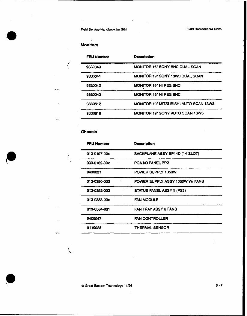
fleM Senrice Handbook for SGI Field Replaceable Units
...
...e.. . .
Monitors
FRU Number Description
( 933OO40 MONITOR 16' SONY BNC DUAL SCAN
9330041 MONITOR 19" SONY 13W3 DUAL SCAN
9330042 MONITOR 19' HI RES BNC
9330043 MONITOR 19' HI RES BNC
933081 2 MONITOR 19' MlTSUBlSHl AUTO SCAN 13W3
933081 8 MONITOR 19' SONY AUTO SCAN 13W3
Chassis
FRU Number Deaciiption
01 3-01 97-00~ ~~ ~ ~~ ~~
BACKPLANE ASSY BP14D (1 4 SLOT)
03041 82-00~ PCA I / O PANEL PP2
9430021 POWER SUPPLY 105oW
~~~
STATUS PANEL ASSY II (PS3)
0 1 3 - 0 ~ 1 FAN TRAY ASSY 6 FANS
9400047 FAN CONTROLLER
91 10035 MERMAL SENSOR _._e ...: ..
0 Great Eastern Technology 11/96 5 - 7

:.:. ..
. .
Cables
FRU Number
Reld Servtce H~dbodc tor SGI
Description ~~
01 8-01 36-001 CBL ASSY CPU TO VO
0184285901 CBL ASSY EXT 13W3 TO 13W3 15’
018-0286-001 CBL ASSY EXT 13W3 TO BNC 25‘
018-0179-002 CBL ASSY EXT SCSl10.5’
CBL ASSY EXT SCSl DB50 to CENTRONICS
0184062-001
01 84088-001
01 8-oO75-Ool CBL KEYBOARD EXTENSION
01 84075-002 ~~
CBL KEYBOARD EXTENSION 1 5
01 841 8-1 CBL VIDEO INT
-
f
Q Great Eastern Technology 11/96
c


