Iournal of Research of the National Bureau of Standards Vol. 48, No.2, February 1 952 Research Paper 2291 Film-Rupture Mechani sm of Str ess Corrosi on Hugh 1. Logan The at mosp herically fo rmed pro tective fi lms were re moved by abras io n in an argon atmo s phere from surfaces of an a luminum alloy, t wo braRses, a magnesium alloy, fi nd 10w- carbon and stainless steels. The resu l ting surfaces were 0.12 to 0.76 volt more n egat ive with respect to It calomel elect rod e t h an su rfa ces prep ared and meas ur ed under normal atmo s pheric conditions. Appreciab le changes in el ectro chemical sol utio n tials of no tched sp ecimen.s , stressed in te nsion occurr ed at or just above s tr esses at wInch the true st r am c ur ves d evi a ted fro;n the modulus lines. These chan ges in p otential were cause d by ruptur ing of t he protective fi lms at the roots of the notche s we;'e of the order of 0.70 v.olt at fa ilu re de pendin O' on the material. Stress oOrroslOn 18 postu la te d to occ ur III corrOSlVe me dia , at st resses to rupt1ll'e the protecti ve film, by elect rol yt ic act io n between the filmed (c3thodi c) an d film-free (anodic) areas. 1. Introduction St rcss-col'l'osion cracking has b een defined as the "spontaneous fa ilme of metal by cracking under the combined action of corrosion and stress, residual or applied" (1).1 Service failures ha ve frequently re- sult ed from residual s tr esses set up in th e mater ial or s tructure durin g fabrication. Th ese tr esses ma y r esult from the spinning or deep drawing of sh eet brass, the work-hard ening of aluminum-alloy tubing, the pr essing of oversized bushings into aluminum- alloy fitting s, the riveting or welding of steel tl'UC- tm es, or even as the result of the appli cation of excessive torques· in the assembling of brass-pipe s tructmes [2]. Stress-corrosion cracking may be eith er int er crystallin e, as in aluminum alloys, a lpha brass, and low-alloy steels, or transcrystalline, as is usually th e case in magnesium-base alloys a nd the au steni tic stainless steels. It is agreed by most workers in the fi eld th at some d egree of stress-corrosion cra cking can be produ ced in many alloys and commercially pur e metals by the proper co mbination,> of stresses and cOl'l'osive media . Th e ASTM-AIMME Symposium on Stress-Corro- sion Cracking of Metals [3 ], published in 1944, gives an excellent summary of work in the fi eld to tha t date. A numb er of pap ers have also a pp ear ed in recent years [4 to 8, 10 ] that co ntain excellent bibliographi es. For the most part, the data in the literatur e are from inv estigations of the relative susceptibilities of various mat e ri als to stress-cor- rosion cracking, susceptibilities of parti cular materi - als to s tr ess corrosion in specific corrosive med ia , or susceptibilities of parti cular materials to stress co rl'o sion aft er var iou s mech anical or thermal treatme nts. The purpose of thi s inv esti gat ion wa to st udy the m ech anism of str ess cOlTosion and not to determin e the relative suscep tibilities of various mat erials to stress corros ion . R ecentl y the various theories of the mechani sm of s tr ess corrosion were summarized by Harwood [ 10] . Of these th eori es the "General- iz ed theory of stress corrosion" proposed by Mear s, Brown , and Dix [11], the "Mech anical theory" of I Figures in brackets indicate the literat ure references at the end of this paper. 99 K eating [5], and the " Film ruptme theory ", 01' b etter, " Film ru p tme m echanism," are pertinent to the pr esent paper. It is considered in this p aper that the " Film rupture mechani sm" and the " Me ch a ni cal theory" are logical parts of the Generalized th eor y. In the Generalized th eory , corrosion is postula ted to occur by an electrochemical mechanism along lo calized p aths th at are anodic to the surrounding metal. Th ere will be stress concentrations at the bases of localized corroded areas; the deeper the att ack and ... "the smaller the radius at the base of the path the greater would be th e stress con ce ntr a- tion. Such a condition would a ct to pull the metal apart along more or less continuous p aths. At suf- fi cient concen tration of s tr ess, the met9.1 might start to teal' apart by mechanical a ction . . . the tear ing action described above would expose fresh metal, unprot ected by films, to the act ion of the corrosive environment . Because this freshly exposed m etal is mor e anodi c, an increa se in current from the base of the localized path to the u nafIected smf ace would be expected ... ". It is secn from t hi s quotation th at M ears and hi s coworkers [11 ] po st ul ate a mech- anism in which pro tect ive films on m etal surfaces ar e r uptmed. K eatin g [5] suggested th at each adva nc- ing section of the cra ck in an o.bstacle in the form of a nonmetalli c lI1clU S lOn , lat tlCe dls- co ntinuity, or unfavo rabl y orienta ted grain boundar y. In each case, the result m ay be re du ction in the s tress- concentration eff ect to a level at which cracking cannot proceed. Such a process would explain bra nching of st ress"colTosion cra cks, sudd e. n changes in dir ect ion at grain boundar ies, etc. Gtlbert a nd Had en [12 ] report the results of an investigat ion on an aluminum alloy containing 7 pel' ce n.t of mag- n esium in which they found th at the crac kmg process was no t continuous but stepwise. There are few published dat a from which the elec- trochemi cal solu tion pot enti al of the freshly torn metal at the root of the crack can be estimat ed. Work at the National Bureau of S tandard s as early as 1940 showed th at the solution potential of freshly quenched or freshly abraded 24S-T a luminum-alloy sh eet \l1as mu ch mor e el ectr onegative (anodic) th an that of the same ma terial permitted to stand for
Transcript
Iournal of Research of the National Bureau of Standards Vol. 48, No.2, February 1952 Research Paper 2291
Film-Rupture Mechanism of Stress Corrosion Hugh 1. Logan
The atmospherically formed protective fi lms were r emoved by abrasion in an argon atmosphere from surfaces of an aluminum alloy, t wo braRses, a magnesium a lloy, find 10wcarbon and stainless steels. The resulting surfa ces were 0 .12 to 0 .76 volt more negative with respect to It calomel electrode t han surfaces prepared and measured under normal atmospheric conditions. Appreciable changes in electrochemical sol ution p~ten tials of notched specimen.s, st ressed in tension occurred at or just above stresses at wInch the true stJ'es~-tl'ue stram curves devia ted fro;n the modu lus lines. These changes in potential were caused by rupturing of t he protective fi lms at the roots of the notches anc~ we;'e of the order of 0.16~0 0.70 v.olt at failure dependin O' on the material. Stress oOrroslOn 18 postula ted to occur III corrOSlVe media, at stresses s~fficient to rupt1ll'e the protective film, by electrolytic actio n between the filmed (c3thodic) and film-free (anodic) areas.
1. Introduction
Strcss-col'l'osion cracking has been defined as the "spontaneous failme of metal by cracking under th e combined a ction of corrosion and stress, residual or applied" (1).1 Service failures have frequ ently resulted from residual stresses set up in the material or s tructure during fabrication . These tresses may result from the spinning or deep drawing of sheet brass, the work-hardening of aluminum-alloy tubing, the pressing of oversized bushings into aluminumalloy fittings, the riveting or welding of s teel tl'UCtm es, or even as the result of the application of excessive torqu es · in the assembling of brass-pipe structmes [2]. Stress-corrosion cracking may be either intercrystalline, as in aluminum alloys, alpha brass, and low-alloy s teels, or transcrystalline, as is usually the case in magnesium-base alloys and the austeni tic s tainless steels.
I t is agreed by most workers in the field that some degr ee of s tress-corrosion cracking can be produced in many alloys and commercially pure metals by th e proper combination,> of stresses and cOl'l'osive media. The ASTM-AIMME Symposium on Stress-Corrosion Cracking of Metals [3], published in 1944 , gives an excellent summary of work in the field to tha t date. A number of papers have also appeared in recent years [4 to 8, 10] that contain excellent bibliographies. For the most part, the data in the literature are from inves tigations of the relative susceptibilities of various materials to s tress-corrosion cracking, susceptibilities of particular materials to stress corrosion in specific corrosive media, or suscep tibilities of particular materials to s tress co rl'osion after various mechanical or thermal treatments.
The purpose of this investigation wa to study the mechanism of str ess cOlTosion and not to determine the relative suscep tibili ties of various materials to stress corrosion . R ecently the various theories of th e mechanism of s tress corrosion were summarized by Harwood [10] . Of these theories the " Generalized theory of stress corrosion" proposed by Mears, Brown, and Dix [11], the "M echanical theory" of
I Figures in brackets indicate the li terature references at the end of this paper.
99
Keating [5], and the "Film ruptme theory", 01' better , "Film rup tme mechanism," are pertinent to the presen t paper. It is considered in this paper that the "Film rupture mechanism " and the " Mecha nical theory" are logical par ts of the Generalized theory.
In the Generalized theory, corrosion is postulated to occur by an electrochemical mechanism along localized paths that are anodic to the surrounding metal. There will be stress concentrations at the bases of localized corroded areas; the deeper the attack and ... "the smaller the radius at the base of the path the greater would be th e stress concentration. Such a condition would act to pull the metal apart along more or less continuous paths. At sufficien t concentration of s tress, the met9.1 might start to teal' apart by mechani cal action . . . the tearing action described above would expose fresh metal, unprotected by films, to the action of the corrosive environment. Because this freshly exposed metal is more anodic, an increase in curren t from the base of the lo calized path to the u nafIected smface would be expected ... ". It is secn from this quotation that M ears and his coworkers [11] postulate a mechanism in which pro tective films on metal surfaces are ruptmed. K eating [5] suggested that each advancing section of the crack in ti~e e.ncou~ters an o.bstacle in the form of a nonmetalli c lI1clUSlOn, lattlCe dlscontinuity, or unfavorably orienta ted grain boundary. In each case, the r esu lt may be reduction in the stressconcentration effect to a level at which cracking cannot proceed. Such a process would explain branching of stress"colTosion cracks, sudde.n changes in direction at grain boundaries, etc. Gtlbert a nd Haden [12] report the results of an investigation on an aluminum alloy containing 7 pel'cen.t of magnesium in which they found that the crackmg process was no t continuous but s tepwise.
There are few published data from which the electrochemical solu tion potential of the freshly torn metal at the roo t of the crack can be estimated. Work at the National Bureau of S tandards as early as 1940 showed that the solution po tential of freshly quenched or freshly abraded 24S-T aluminum-alloy sheet \l1as much more electronegative (anodic) than that of the same material permitted to stand for
l
some minutes before measurements were made [13] . Similar results were recently obtained at the Bureau on 18-percent-Cr- 8-percent-Ni austenitic stainless steels. Mears and Brown [14] report a solution potential greater than - 3.0 v for commercially pure aluminum from which the film was removed by scratching the surface with a glass stylus in the electrolyte. Druet and Jacquet [15] report values of - 0.75 v for mechanically polished specimens containing 99.99 percent of aluminum (presumably with a protective film intact) and - 1.384 v for the same material with measurements made immediately after electrolytic polishing.
The author is not aware of any data giving the magnitude of changes in solution potential produced by rupture of protective films on the metals or alloys that are particularly susceptible to stress corrosion. Such data are necessary to establish the validity of the so-called film rupture process in the generalized theory of stress corrosion. In the early phases of the investigation of the mechanism of stress corrosion, the following have been determined and are reported in this paper: (a) the electrochemical solution potentials of several alloys free from the protective effects of films,2 and (b) relationships between the applied stresses and the electrochemical solution potentials of these alloys.
2 . Materia ls a nd Methods of Test
The materials used in this investigation were 24ST4 aluminum alloy, 70-percent-Cu- 30-percent-Zn
' It is recognized that con tact oran electrolyte, at least with the aluminum and magnesium alloys studied , may produce a protective film on the metal surfaces.
cartridge brass, 61-percent-Cu- 36-percent-Zn- 3-percent-Pb leaded brass, AZ3lf magnesium alloy, lowcarbon steel, and type 302 stainless steel. The chemical compositions are given in table 1. The aluminum alloy, the leaded brass, and the steels were obtained commercially. The magnesium alloy was supplied by the Dow Chemical Co., and the cartridge brass was made in the Bureau's Experimental Foundry from electrolytic copper and 99.99-percent zinc. Prior to machining of the specimens, the materials were heat treated as follows : (a) The aluminum-alloy stock was solution heat-treated at 920 0 ± 10° F , and quenched in water at approximately 70° F , (b) the cartridge brass was rolled to a diameter of about 0.62 in. and then annealed for 1 hour at 1,560° F , after which the Brinell hardness number was 6(l and the grain size approximately 0.025 mm, (c) the low-carbon steel, originally in the cold-rolled condition, was heated to 1,625° F and cooled with the furnace , (d) the stainless steel was heated to 1,950° F and quenched in cold water. The magnesium alloy, in the form of an extruded rod 76 in. in diameter, and the leaded-brass rod, 76 in. in diameter, were used as received. The magnesium alloy evidently had been extruded at a sufficiently high temperature that the metal had recrystallized following extrusion. The leaded brass had a Brinell hardness number of 113 and a grain size of 0.015 to 0.025 mm. The tensile properties, as determined on subsize (0.355-in. diameter) ASTM round tensile specimens, are given in table 2.
When the protective film on 24S- T4 aluminum alloy is broken in air, it tends to repair itself quite rapidly. Therefore, specimens were prepared by
TABLE 1. Chemical composition of metals used
Material Al C Cr Cu Fe Pb M n M g Ni P Si 8 Zn 1-----------------------------------
• Determined spectroscopically. b By difference. • Manufacturer 's analysis.
T ABLE 2. lIfechanical properties of metals used
M aterial
248- '1'4 aluminum allo y ___ ___ ____ _ Cartrid ge brass ____ __________ ____ _ Leaded brass ___ __ ___________ ____ _ AZ3lf magnesium alloy _________ _ Low-carbon stoel ________ ________ _ Type 302 stainless steeL _________ _
Ultimate tensile
strength
1,000 Ullin.' 69. 4 48.1 54.6 41. 0 54.7 91. 1
Yield strength
1,000 lblin.' 42.5 16.3 43.6 33.5 31. 5 33.5
Elongation in 1.4 in .
Perce 'li t 24 54 28 II 40 77
abrading them with "400 aloxite" metallographic polishing paper, and all measurements were made in an argon atmosphere 3 in a dry box. In making measurements , drops of the desired electrolyte were
3 An analysis of the argon by the mass spectrograph method showed 0.2 percent of -,\, as (he only dctectable impurity .
% % % % % % % % 0.6 1.4 0. 1
b 30. 6 3.0 b 35. 8
.4 . 03 1.0
.81 0. 005 . 019 0.024
.38 8.63 . 017 . 297 . 013
placed on the prepared surface and brought into electric contact with a calomel electrode of the saturated KCl type by means of an agar-agar bridge. Potential measurements were made with a pH meter, or for values in excess of 1.3 v, with the pH meter in series with a L&N type K potentiometer.
It was recognized that the preparation of the speci.,. men surfaces by abrasion left the surfaces to be measured in the cold-worked condition and might produce phase changes in the stainless steel. In some earlier work at the Bureau the author reduced the thickness of some 24S- T4 aluminum-alloy sheet approximately 5 percent .without appreciable changing its solution potential. Druet and Jacquet [15J showed that severely cold-worked high-purity aluminum was only about 0.04 v more negative than the annealed material. The author has seen no data on
100
the effect of cold-wod,;: on the solution potentials of other materials studied nor no the effect of a phase change on the solution potential of the stainless steel.
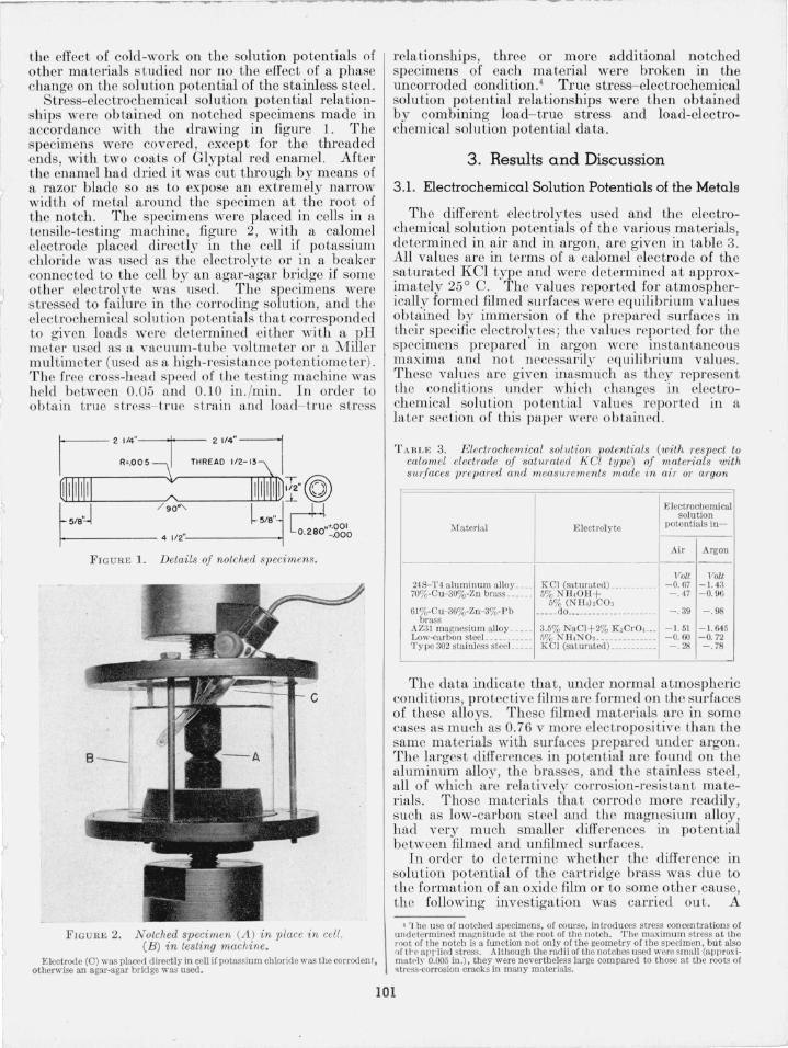
Stress-electroch emical solution potential relationships were obtained on notched specimens made in accordance wi th the drawing in figure 1. The specimens were covered, except for the threaded ends, with two coats of Glyptal red enamel. After the enamel had dried it was cut through by means of a razor blade so as to expose an extremely narrow width of metal around the specimen at the root of the notch . The specimens were placed in cells in a tensile-testing machine, figure 2, with a calomel electrode placed directly in the cell if potassium chloride was used as th e electrolyte or in a beaker connected to the cell by an agar-agar bridge if some other electrolyte was used . The specimens were s tressed to failure in the corroding solution, and the electrochemical solution potentials that corresponded to given loads were determined either with a pH meter used as a vacuum-tube voltmeter or a Miller multimeter (used as a high-resistance potentiometer). The free cross-head speed of the testing machin e was held between 0.05 and 0.10 in. /min. In order to obta,in true s tress- true strain and load- true stress
FIG URE L Details of notched specimens.
FIG URE 2. Notched specimen V l ) in place in cell , CB) in testing machine.
Electrode (0) was placed directly in cell if potassium chloride was the corrodent, otherwise an agar-agar bridge was used.
relationships, three or more additional notched specimens of each material were broken in the uncorroded condition_4 True stress- electrochemical solution potential r elationships were then obtained by combining load- true s tress and load-electrochemical solution potential data.
3. Results and Discussion
3.1. Electrochemical Solution Potentials of the Metals
The different electrolytes used and the electroch emical solu tion potentials of the various materials, determined in air and in argon, are given in table 3. All values are in terms of a calomel electrode of the saturated KCl type and were determined at approximately 25 ° C. The values reported for atmospherically formed filmed surfaces were equilibrium values obtained by immersion of the prepared surfaces in th eir specific electrolytes; the values reported for the specimens prepared in argon were instantaneous maxima and not necessarily equilibrium values. These values are given inasmuch as they represen t the conditions under which changes in electroch emical solu tion po tential values reported in a la ter sec tion of this paper were obtained.
T A B I_E 3. Electrochemical solution 1Jolentials (with res pect to calomel electTode oj satumted ]( Cl type) of maleTials '»ilh SUTJaces pTepared and measurements made in air or argon
Electrochemical solution
Material Electrolyte poteutials iu-
Air Argon -- - - --
]TaU Volt 248-'1'4 alu minum alloy ____ KCI (saturated) ___________ -0.67 -1.43 70%-Cu-30%-Zn brass __ ____ 5% NII.Oil+
The data indicate that, under normal atmospheric conditions, pro tective films arc formed on the surfaces of these alloys. These filmed materials are in some cases as much as 0.76 v more electropositive than the same materials with surfaces prepared under argon. The largest differences in potential are found on the aluminum alloy, the brasses, and the stainless steel , all of which arc relatively corrosion-resistant materials. Those materials that corrode more readily, such as low-carbon steel and the magnesium alloy, h ad very mu ch smaller differences in potential between filmed and unflimed surfaces.
In order to determine whether th e difference in solution po tential of the cartridge brass was due to the formation of an oxide film or to some oth er cause, the following investigation was carried out. A
4 '1 he use of notched specimens, of course, introduces stress concentrations of undetermined magnitude at tbe root of the notch . The maxim um stress at the root of the notch is a function not only of the geometry of the specimen , but also of tr~ arrlicd stress. Although tbe radii of the notches used wcre small (approximat~l)' 0.005 in.), they were nevertheless large compared to those at the roots of .tress-corrosion cracks in many materials.
101
-----~---------~
sp ecimen was placed in the dry box, and a surface was prepared and measured under argon . Approximately 20 percen t of the argon was then replaced by dry oxygen, and additional measurements wore m ade on the same surface. The eJo.'}) erimen t was rep eated wi th wet oxygen, wet carbon dioxide, and dry ammonia gas. The resul ts are given in table 4 .
TABLE 4. Electrochemical solution potentials of 70%-Cu- 30 %Zn brass with surfaces prepw'ed in an argon atmosphere and measurements made in a mixed atmosphere
It will be no ted tha t in every caso the solution po ten tial was more positive after the addition of the second gas, the change being most marked in the case of oxygen, either dry or wet . In the a tmosphere containing ammonia, the surface of the alloy adjacen t to drops of liquid used in making the measuremen ts became tarnished ; its final po tential was - 0.31 v compared to - 0.47 v for brass measured in air . M easuremen ts made on the surfaces of brass specimens covered with a blue corrosion product after exposure to an a tmosphere containing ammonia, carbon dioxide, air, and wa ter vapor were 0.75 v more electropositive than film-free surfaces of the same alloy.
The relationships between the tru e stresses and electrochemical solution po tentials of the materials are shown in figures 3 to 8. T he maximum values of tbe potentials were usually ob tained just a t the failure of the specimen as the resul t of the exposure of large areas of unfilmed ma terial. These values are of course not shown on the figures but a re given in table 5. In any measurement of electrochemical solu tion potentials the measured po ten tials are
TABLE 5. Maximum change in electrochemical solution potential with stress.
Material Electrolyte
24S-T4 aluminum alloy. _____ Saturated KCI. ____________ _ 70%·Cn-30%·Zn Brass . . _____ 5% Nll.Oll+5% (Nll.hCO, 61 % -C u - 36% ·Z n- 3% · P b _____ do _____ _________________ _
Corrod ing medium, satu rated KCI. Data are from seven specimens.
TRUE STRAIN , LOGe Ao /A . 100 .200 . 300 .400
100 ,---,----,---,--,---,-- ---;,--,---,--,
90
80
70
N· co 60
" .0
g 50 Q
(Jl
~ 4 0 0: f(Jl
w ij!30 f- I
I 20 I
10
/ I
/ /
----/' ;/ /''---- -----
- l!.V RANGE "-..
/ /
/ /
/ /
/- TRUE STRESS - TRUE STRAIN /
O . 100 200 300 400 500 600 700 800 900
b.VoVi -Vo, Millivolls
FIGU RE 4. True stress-electrochemical solution potential relationships for 70 percent Cu-SO percent Zn cartridge brass.
Corroding medium, 5 percent Nll.Oll +5 percent (Nll.) 2C03. Data are from seven speCimens.
102
•
necessarily the integrated potentials over the entire area in contact with the electrolyte. It is therefore to be expected that potential measurements made on notched specimens of the same material may vary somewhat from specimen to specimen, hence t he ranges of potential at given true stresses rather than average cUl"ves arc shown in the graphs.
There wa an appreciable change in the solu tion potential of the aluminum alloy (fig. 3) at stresses at which the true stress- true strain curve deviated from the modulus line, that is, at stresses at which plastic deformation had occurred. Marked changes in the potentials of the bra specimens (figs. 4 and 5) occurred at stresses that were 10,000 to 25,000 Ib/in.2
above those at which the true stress- true strain curves deviated from the modulus line. The solution potential of the magnesium alloy changed appreciable at stres es only about one-third of those necessary to produce deviation from the modulus line (fig. 6). The yield point in the low-carbon steel wa accompanied by a marked change in potential (fig. 7) . tre se sufficient to produce a deviation of the true stresstrue train curve from the modulus line for stainles steel al 0 produced appreciable changes in the olution potential (fig . ). The electrochemical
solution potentials (except for the low-carbon steel) became increasingly more negative a the stresses were increa cd. For every material (except lowcarbon steel) stre ses were reached, as is seen in fi gures 3,4, 5, 6 and 8, at which the slope of the true stress-potenLial curves decreased markedly, and the
TRUE STRAIN, LOG e Ao/A
. 20 .40 .60 .80 100
90 f::, V RANGE ____
---\ ---\/ ---80 /\ /
/ (\Ie 70 - I-
" 7 "" g 60 / ~ TRUE STRESS - TRUE STRAIN
::: ~ 50 / w / 0: l-
I <fl
W 40 / :::::> 0: I l-
I 30 I
1
20 1 1
10
0 0 100 200 300 400
l:::.V= Vi -Vo, Millivolts
F IGURE 5. True stl'ess-electTochemical solution potential Te lationships jor leaded bmss.
Corroding medium ,5 percent N lI. OlI +5 perce nt (NH.12C03. Data arc from fi ve specimens.
Corroding mediu lll , 3.5 percent NaCl +2.0 percent K,CrO.. Data arc from eight speci mens .
pote,ntial increased rapidly to the failure of the speCImen.
It is postulated that during the loading of the specimens in tension the protective film is broken over minute areas of the surface. If the potential of the unprotected area alone could be measured, it would presumably be of the same order of magnitude as that determined on a film-free surface. The area where the film has been ruptured is very small compared with that of the filmed surface of a specimen, and consequently the measured potential differ by only a small amount from that obtained on an unbroken filmed surface. As the s tresses are increased the ratio of the film free to the filmed surface of a specimen increases, and the solu tion potential becomes more negative, until at the instant of fracture the area of unfilmed surface may be very large compared to that of the filmed surface, and the potential may closely approach ' that of completely unfilmed material.
At a constant stress the protective film tend to repair itself. This was demonstrated by results obtained on aluminum-alloy pecimens. After an appreciable change had been obtained in the solution potential during loading, the applied load was held constant, and within 1 minute the solution potential was the same as that of the unstressed specimen. After the pecimens broke (exposing large unfilmed areas) the electrochemical solu tion po tentials rapidly
103
assumed the same values as those of the filmed and unstressed materials.
Examination of the fractured surfaces of the no tched pecimens and the marked changes in the potentials of all of the materials except low-carbon steel at fracture indicated that the final failure had been almost instantaneous. In the low-carbon teel specimens, however, bo th the appearance of the fracture and the small change in po tentials at failure indicated that prior to the final fracture , cracks had
. penetrated into the material from th e roots of the notches and that the progression of fracture was not rapid and was probably discontinuous. Consequently, at failure the amount of freshly exposed unfilmed metal was too small to produce any marked change in the po tential.
The data indicate that when the stresses are high enough to cause plastic deformation the atmospherically formed protective film will be broken and the exposed metal will become electronegative with respect to the filmed material. These film-free areas will, in general, be very small compared to the filmed areas. If such areas are connected to filmed areas by a conducting liquid, for example, by a drop of liquid containing dissolved gases or salts, a short-circuited electrolytic cell will be set up, the circuit being com-
N. c:
" ~ 0 0 Q
If)-
If) W a: ... <J)
w :> a: ...
110
100
90
BO
70
60
50
/
I /
/
TRUE STRAIN, LOG e Ao/A
. 100 200 .300 .400
/
/ /
/\ /
/' /
/
/ TRUE STR ESSTRUE STRAI N
I - t:,v RANGE --
50 100
/'
C::.V= Vi- Vo , Millivolts
1/// ./
./
150 200
FIGURE 7. Tnle stress-electrochemical solution potential relationships for low-carbon steel.
Corroding medium, 5·percent N il,NO,. Data are from nine specimens.
F IGURE 8. True stress-electrochemical solution potential relationships for type 302 stainless steel specimens.
Corroding mcclinm, saturated Kel. Data are from six specimens.
pleted through the metal itself. As the film-free (anodic) area is generally very small compared with the filmed area, the current density over the anodic area will be high, and corrosion will proceed at a rapid rate until a readjustment of stresses permi ts reforming of the pro tective surface film . Corrosion will then become more general (or stress corrosion will proceed along different paths) until the stress concentration at the particular path under consideration again becomes sufficient to rupture the protective film . The author believes that successive breaks in the time-potential curves reported by Gilbert and Haden [12] indicate that such processes were occurring, probably at several points, on their test specimens.
The experiments reported in this paper confirm the gencral idea of the film-rup ture mechanism suggested by Mears, Brown, and Dix. In the theory as first presen ted, i t was postulated tha t tearing of the metal was necessary to expose film-free material. However , the present data indicate that film rupture occurs with comparatively small amounts of plastic deformation of the underlying material. When the film ruptures, s tress corrosion may s tart in the filmfree areas at stresses much below those normally required to tear the metal apart. Unless conditions ' permi t film repair, stress corrosion may progress to cause completc failure in a rclatively shor t time. If the film i restored and the stresses are not increased or readjusted, stress corrosion niay cease. If, however , the stresses are readjusted by any means whatsoever , for example, by a change of external load or by corrosion, the film may again be broken and
it I
104
rY ..
stress corrosion proceed discontinuou ly to failure. The last proce may be that which occurs in the tran crystalline type of stress corrosion.
4. Summary
A a part of a detailed study of the mechanism of stre corrosion, the electro chemical solution poten
') tials of filmed and film-free surfaces and the true stres - electrochemical solution potential relationships for everal alloys were determined.
The electrochemical solution po tentials of surfaces, from which the atmospherically formed films had been removed by abrasion in an inert atmosphere, were 0.10 to 0.76 v more electronegative (with
;:0 respect to a calomel electrode) than filmed surface of the sam e materials.
Appreciable changes in electrochemical solution potentials accompanied plastic deformation, and just prior to fracture the olution potentials were 0.16 to 0.70 v (depending on the alloy) more electronegative than the unstressed material.
.r. The result of the investigation indicate that at
.. stre cs sufficientl), hjgh to produce failure of tIle protective film on metals, stre s corrosion occurs in a corrosi e medium by electroly tic action between film-free (anodic) and filmed (cathodic) areas. The process proceeds continuously or discontinously to failure, depending on whether or not the subsequent
~ adju tment of tresses permits reforming of the protective fLlm .
I
I
L
The author gratefully aelmowledge the help of Thomas P . Royston, Jr. , in obtaining the data presented in thi paper.
5 . References [1] Metals Hand book, p . 14, 1948 ed. (Am. Soc. Metal ,
. Cleveland, Ohio). [2] W. B. Price, Am. Inst. Mining E ngrs. 89, 268 (1930). [3] Sy mposium on Stress-Corrosion Cracking of Metals,
[4] U. R . Evan s, Symposium on Internal Stresses in Metals and Alloys, Inst. Metals, p . 309 (1948).
[5] F. H . Keating, Symposium on In ternal Stresses in Metals and Alloys, Inst. Metals, p . 329 (1948).
[6] E. H ugony, Alluminio 17, 225 (1948). [7] C. A. Zapife, Trans. Am. Soc. Mech . Eng. 66, 81 (1944). [8] H . P . Croft and G. Sachs, Iron Age 151, 47 (March 11,
1943); 151, 62 (March 18, 1943). [9] H . P . Croft, Proc. Am. Soc. Testing Materia ls 4,1 ,
905 (1941). [10] J . J . Harwood, Co rl'Osion 6, 249 a nd 290 (1950). [Il] R. B. Mear, R. H . Brown, and E. H . D ix, Jr., ym
po~ium on SLress-Corrosion Cracking of Meta ls, Am. Soc. Testing l\laLerials-Am. Inst. Mining Engrs., p. 329, 1944 (Am. Soc. Testin g Materi als, Philadelphia, Pa.) .
[12] P . T . Gi lbert and . E. H aden, J . I nst. Ietals 77, 237 (May 1950).
[13] H . L. Logan , J . Research II BS 25, 315 (1940) RP 1328. [14] R. B. Mears and H. H . Brown, I nd. Eng. Chem. 33,
1001 (1941). [15] Y . Druet and P . A. Jacquet, Metaux &; Corrosion 22,