ENCOAL Mild Coal Gasification Project Final Reports — September 1997 DE-FC21-90MC27339 Final Design Modifications Report This report general contents page has been set up with each section linked to the page where the corresponding section begins. To use this feature, move your cursor to the section you wish to view. (Your cursor arrow will change to a pointing finger.) Click your left mouse button to jump to the correct page in the report. Cover Disclaimer Trademark Notice ......................................................... ii Contents pages ........................................................... iii Glossary ................................................................ vi 1.0 — Introduction ........................................................ 1 2.0 — Background Information .............................................. 1 3.0 — Overview of Process ................................................. 7 4.0 — Plant Equipment Modifications ......................................... 10 5.0 — Plant Utility Modifications ............................................. 29 6.0 — Environmental Modifications ........................................... 38 7.0 — Safety and Administrative Items ......................................... 42 8.0 — Conclusions ........................................................ 42 References .............................................................. 45 Appendix To return to the primary Contents page or the Cover of the ENCOAL Project reports, click the Go Back button (the double left-pointing arrow) from the tool bar at the top of the screen, or choose Go Back from the view menu.
Transcript
ENCOAL Mild Coal Gasification ProjectFinal Reports — September 1997 DE-FC21-90MC27339
Final Design Modifications Report
This report general contents page has been set up with each section linked to the page where thecorresponding section begins. To use this feature, move your cursor to the section you wish to view. (Your cursor arrow will change to a pointing finger.) Click your left mouse button to jump to thecorrect page in the report.
To return to the primary Contents page or the Cover of the ENCOAL Projectreports, click the Go Back button (the double left-pointing arrow) from the tool barat the top of the screen, or choose Go Back from the view menu.
DOE/MC/27339-5797(DE98002006)
ENCOAL MILD GASIFICATION PROJECT:
FINAL DESIGN MODIFICATIONS REPORT
PREPARED BY:
ENCOAL CORPORATIONP.O. BOX 3038
GILLETTE, WYOMING 82717-3038
PREPARED FOR:
THE UNITED STATES DEPARTMENT OF ENERGYUNDER DOE INSTRUMENT NO. DE-FC21-90MC27339
SEPTEMBER 1997
Disclaimer
This report was prepared as an account of work sponsored by an agency of the United StatesGovernment. Neither the United States Government nor any agency thereof, nor any of theiremployees, makes any warranty, express or implied, or assumes any legal liability or responsibilityfor the accuracy, completeness, or usefulness of any information, apparatus, product, or processdisclosed, or represents that its use would not infringe privately owned rights. Reference hereinto any specific commercial product, process, or service by trade name, trademark, manufacturer,or otherwise does not necessarily constitute or imply its endorsement, recommendation, orfavoring by the United States Government or any agency thereof. The views and opinions ofauthors expressed herein do not necessarily state or reflect those of the United States Governmentor any agency thereof.
Available to DOE and DOE contractors from the Office of Scientific and Technical Information,P.O. Box 62, 175 Oak Ridge Turnpike, Oak Ridge, TN 37831; prices available at (423) 576-8401, fax — (423)576-5725, E-mail — [email protected]
Available to the public from the National Technical Information Service, U.S. Department ofCommerce, 5285 Port Royal Road, Springfield, VA 22161; phone orders accepted at (703) 487-4650.
TRADEMARK NOTICE
LFC, ENCOAL, PDF, and CDL are registered trademarks of the TEK-KOL Partnershipthat describe the process, technical services and products associated with the LFC Technologydeveloped and owned by TEK-KOL and its owners, SGI International and Zeigler Coal HoldingCompany. For simplification and readability purposes, the trademark symbols will not be usedbeyond this point in the attached paper.
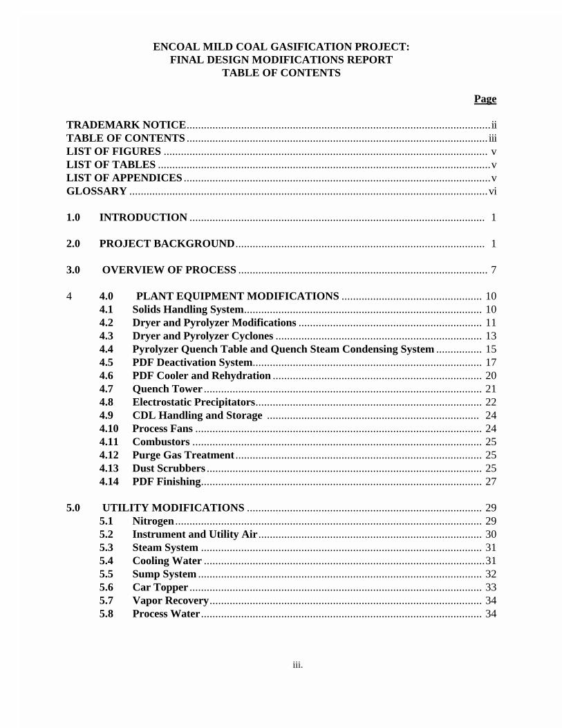
TRADEMARK NOTICE ..........................................................................................................iiTABLE OF CONTENTS ......................................................................................................... iiiLIST OF FIGURES ................................................................................................................. vLIST OF TABLES ....................................................................................................................vLIST OF APPENDICES ...........................................................................................................vGLOSSARY .............................................................................................................................vi
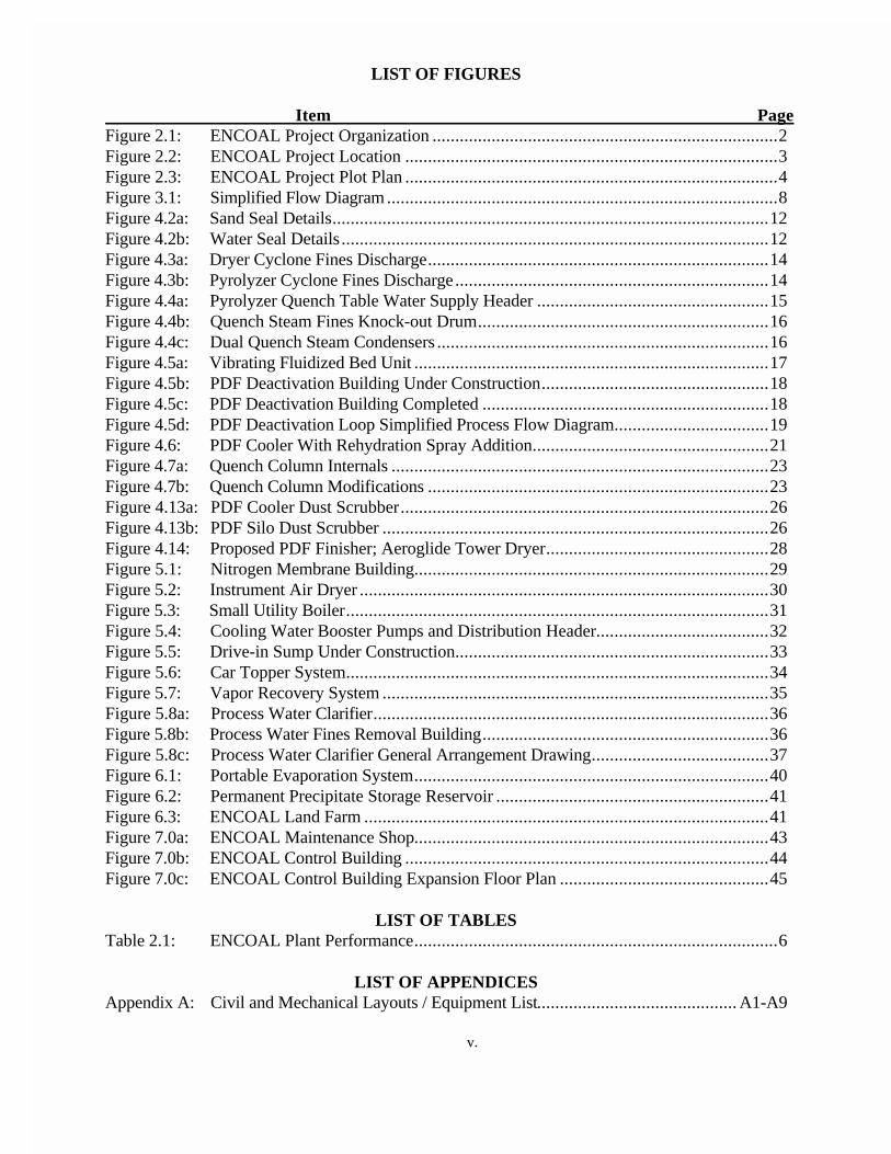
Item PageFigure 2.1: ENCOAL Project Organization............................................................................2Figure 2.2: ENCOAL Project Location..................................................................................3Figure 2.3: ENCOAL Project Plot Plan..................................................................................4Figure 3.1: Simplified Flow Diagram......................................................................................8Figure 4.2a: Sand Seal Details................................................................................................12Figure 4.2b: Water Seal Details..............................................................................................12Figure 4.3a: Dryer Cyclone Fines Discharge...........................................................................14Figure 4.3b: Pyrolyzer Cyclone Fines Discharge.....................................................................14Figure 4.4a: Pyrolyzer Quench Table Water Supply Header...................................................15Figure 4.4b: Quench Steam Fines Knock-out Drum................................................................16Figure 4.4c: Dual Quench Steam Condensers.........................................................................16Figure 4.5a: Vibrating Fluidized Bed Unit..............................................................................17Figure 4.5b: PDF Deactivation Building Under Construction..................................................18Figure 4.5c: PDF Deactivation Building Completed...............................................................18Figure 4.5d: PDF Deactivation Loop Simplified Process Flow Diagram..................................19Figure 4.6: PDF Cooler With Rehydration Spray Addition....................................................21Figure 4.7a: Quench Column Internals...................................................................................23Figure 4.7b: Quench Column Modifications...........................................................................23Figure 4.13a: PDF Cooler Dust Scrubber.................................................................................26Figure 4.13b: PDF Silo Dust Scrubber.....................................................................................26Figure 4.14: Proposed PDF Finisher; Aeroglide Tower Dryer.................................................28Figure 5.1: Nitrogen Membrane Building..............................................................................29Figure 5.2: Instrument Air Dryer..........................................................................................30Figure 5.3: Small Utility Boiler.............................................................................................31Figure 5.4: Cooling Water Booster Pumps and Distribution Header......................................32Figure 5.5: Drive-in Sump Under Construction.....................................................................33Figure 5.6: Car Topper System.............................................................................................34Figure 5.7: Vapor Recovery System.....................................................................................35Figure 5.8a: Process Water Clarifier.......................................................................................36Figure 5.8b: Process Water Fines Removal Building...............................................................36Figure 5.8c: Process Water Clarifier General Arrangement Drawing.......................................37Figure 6.1: Portable Evaporation System..............................................................................40Figure 6.2: Permanent Precipitate Storage Reservoir............................................................41Figure 6.3: ENCOAL Land Farm.........................................................................................41Figure 7.0a: ENCOAL Maintenance Shop..............................................................................43Figure 7.0b: ENCOAL Control Building................................................................................44Figure 7.0c: ENCOAL Control Building Expansion Floor Plan..............................................45
LIST OF TABLESTable 2.1: ENCOAL Plant Performance................................................................................6
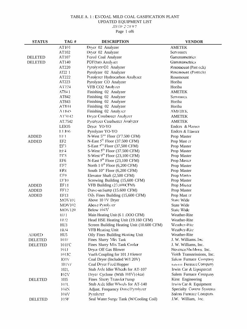
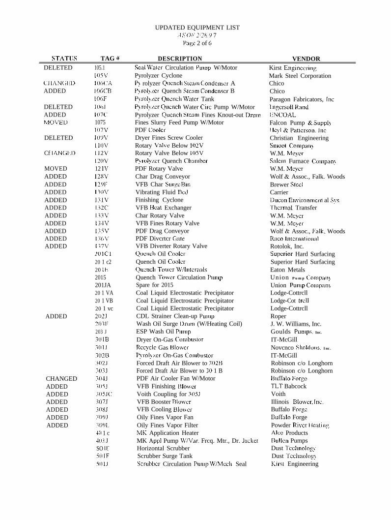
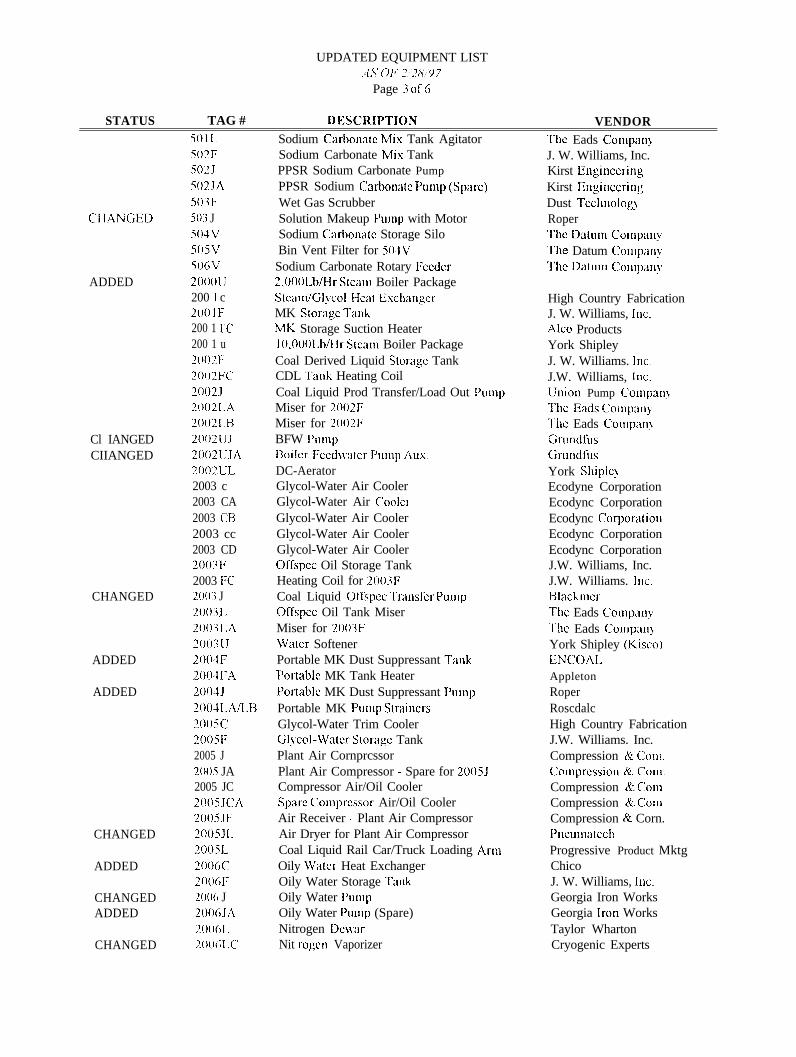
LIST OF APPENDICESAppendix A: Civil and Mechanical Layouts / Equipment List............................................A1-A9
v.
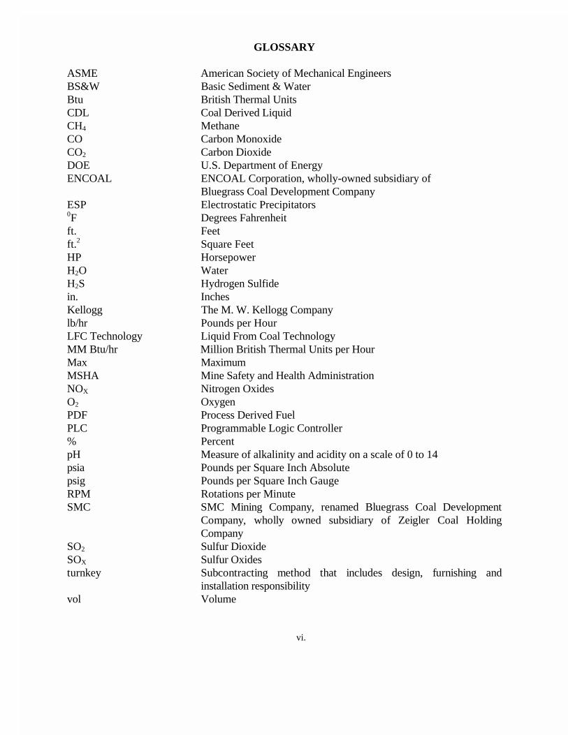
GLOSSARY
ASME American Society of Mechanical EngineersBS&W Basic Sediment & WaterBtu British Thermal UnitsCDL Coal Derived LiquidCH4 MethaneCO Carbon MonoxideCO2 Carbon DioxideDOE U.S. Department of EnergyENCOAL ENCOAL Corporation, wholly-owned subsidiary of
Bluegrass Coal Development CompanyESP Electrostatic Precipitators0F Degrees Fahrenheitft. Feetft.2 Square FeetHP HorsepowerH2O WaterH2S Hydrogen Sulfidein. InchesKellogg The M. W. Kellogg Companylb/hr Pounds per HourLFC Technology Liquid From Coal TechnologyMM Btu/hr Million British Thermal Units per HourMax MaximumMSHA Mine Safety and Health AdministrationNOX Nitrogen OxidesO2 OxygenPDF Process Derived FuelPLC Programmable Logic Controller% PercentpH Measure of alkalinity and acidity on a scale of 0 to 14psia Pounds per Square Inch Absolutepsig Pounds per Square Inch GaugeRPM Rotations per MinuteSMC SMC Mining Company, renamed Bluegrass Coal Development
Company, wholly owned subsidiary of Zeigler Coal HoldingCompany
SO2 Sulfur DioxideSOX Sulfur Oxidesturnkey Subcontracting method that includes design, furnishing and
installation responsibilityvol Volume
vi.
1
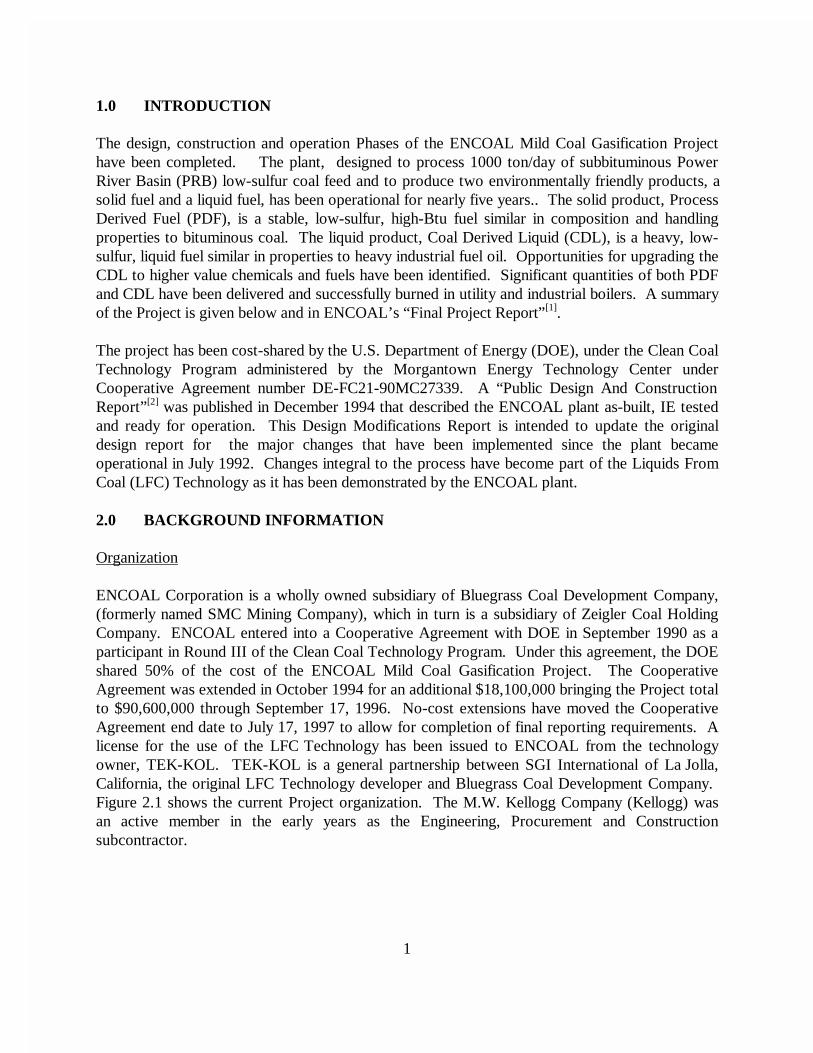
1.0 INTRODUCTION
The design, construction and operation Phases of the ENCOAL Mild Coal Gasification Projecthave been completed. The plant, designed to process 1000 ton/day of subbituminous PowerRiver Basin (PRB) low-sulfur coal feed and to produce two environmentally friendly products, asolid fuel and a liquid fuel, has been operational for nearly five years.. The solid product, ProcessDerived Fuel (PDF), is a stable, low-sulfur, high-Btu fuel similar in composition and handlingproperties to bituminous coal. The liquid product, Coal Derived Liquid (CDL), is a heavy, low-sulfur, liquid fuel similar in properties to heavy industrial fuel oil. Opportunities for upgrading theCDL to higher value chemicals and fuels have been identified. Significant quantities of both PDFand CDL have been delivered and successfully burned in utility and industrial boilers. A summaryof the Project is given below and in ENCOAL’s “Final Project Report”[1].
The project has been cost-shared by the U.S. Department of Energy (DOE), under the Clean CoalTechnology Program administered by the Morgantown Energy Technology Center underCooperative Agreement number DE-FC21-90MC27339. A “Public Design And ConstructionReport”[2] was published in December 1994 that described the ENCOAL plant as-built, IE testedand ready for operation. This Design Modifications Report is intended to update the originaldesign report for the major changes that have been implemented since the plant becameoperational in July 1992. Changes integral to the process have become part of the Liquids FromCoal (LFC) Technology as it has been demonstrated by the ENCOAL plant.
2.0 BACKGROUND INFORMATION
Organization
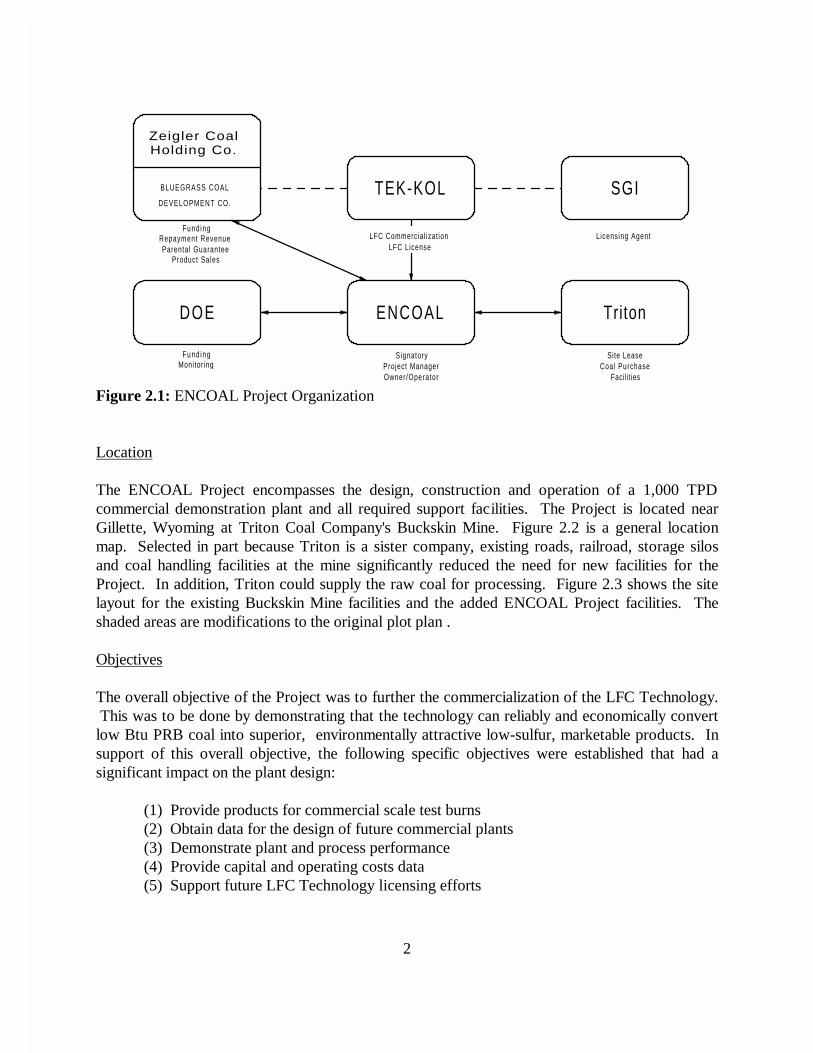
ENCOAL Corporation is a wholly owned subsidiary of Bluegrass Coal Development Company,(formerly named SMC Mining Company), which in turn is a subsidiary of Zeigler Coal HoldingCompany. ENCOAL entered into a Cooperative Agreement with DOE in September 1990 as aparticipant in Round III of the Clean Coal Technology Program. Under this agreement, the DOEshared 50% of the cost of the ENCOAL Mild Coal Gasification Project. The CooperativeAgreement was extended in October 1994 for an additional $18,100,000 bringing the Project totalto $90,600,000 through September 17, 1996. No-cost extensions have moved the CooperativeAgreement end date to July 17, 1997 to allow for completion of final reporting requirements. Alicense for the use of the LFC Technology has been issued to ENCOAL from the technologyowner, TEK-KOL. TEK-KOL is a general partnership between SGI International of La Jolla,California, the original LFC Technology developer and Bluegrass Coal Development Company. Figure 2.1 shows the current Project organization. The M.W. Kellogg Company (Kellogg) wasan active member in the early years as the Engineering, Procurement and Constructionsubcontractor.
2
DOE ENCOAL Triton
SGITEK-KOL
Zeigler CoalHolding Co.
BLUEGRASS COAL
DEVELOPMENT CO.
Coal PurchaseFacilit ies
Site Lease
Licensing Agent
Owner/OperatorProject Manager
Signatory
LFC LicenseLFC Commercial izat ion
Monitor ingFund ing
Product SalesParental Guarantee
Repayment RevenueFund ing
Figure 2.1: ENCOAL Project Organization
Location
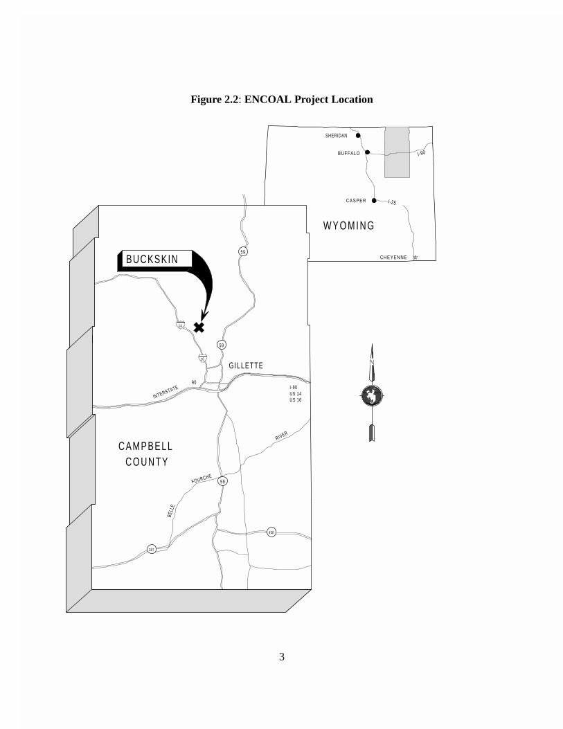
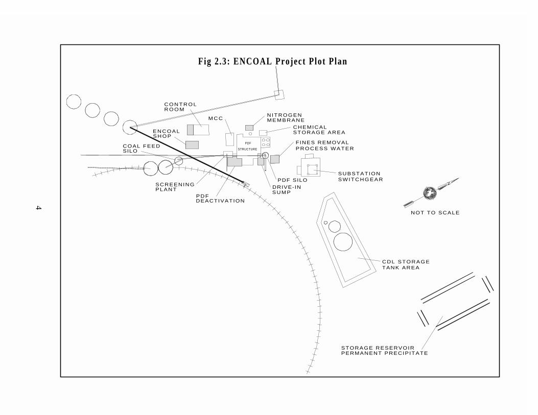
The ENCOAL Project encompasses the design, construction and operation of a 1,000 TPDcommercial demonstration plant and all required support facilities. The Project is located nearGillette, Wyoming at Triton Coal Company's Buckskin Mine. Figure 2.2 is a general locationmap. Selected in part because Triton is a sister company, existing roads, railroad, storage silosand coal handling facilities at the mine significantly reduced the need for new facilities for theProject. In addition, Triton could supply the raw coal for processing. Figure 2.3 shows the sitelayout for the existing Buckskin Mine facilities and the added ENCOAL Project facilities. Theshaded areas are modifications to the original plot plan .
Objectives
The overall objective of the Project was to further the commercialization of the LFC Technology. This was to be done by demonstrating that the technology can reliably and economically convertlow Btu PRB coal into superior, environmentally attractive low-sulfur, marketable products. Insupport of this overall objective, the following specific objectives were established that had asignificant impact on the plant design:
(1) Provide products for commercial scale test burns(2) Obtain data for the design of future commercial plants(3) Demonstrate plant and process performance(4) Provide capital and operating costs data(5) Support future LFC Technology licensing efforts
3
Figure 2.2: ENCOAL Project Location
RIVER
FOURCHE
BELL
E
387
450
W Y O M I N G
BUCKSKIN
COUNTYCAMPBELL
BUFFALO
CHEYENNE
CASPER
SHERIDAN
I-25
I-90
US 16US 14I-90
16
14
INTERSTATE90
59
GILLETTE
59
59
4
NOT TO SCALE
FINES REMOVALP R O C E S S W A T E R
STORAGE AREACHEMICAL
PDF SILO
R O O MC O N T R O L
SCREENINGPLANT
COAL FEEDSILO
S H O PE N C O A L
DEACTIVATIONPDF
SUMPDRIVE-IN
STRUCTURE
M C CNITROGENMEMBRANE
PDF
STORAGE RESERVOIRPERMANENT PRECIPITATE
CDL STORAGETANK AREA
S W I T C H G E A RSUBSTATION
Fig 2.3: ENCOAL Project Plot Plan
5
Given these objectives, the project team charged with the responsibility of designing the facilitiesdeveloped an additional set of guidelines to further define the requirements and aid in the design:
(1) Keep scale-up from the SGI pilot plant reasonable.(2) Use currently available commercial equipment as much as possible.(3) Keep the process simple, postpone the refinement of CDL.(4) Match the products to existing markets.(5) Minimize all releases to the environment.
ENCOAL’s processing plant was designed to commercial standards for a life of at least 10 years. It used commercially available equipment as much as possible, state-of-the-art computer controlsystems, BACT for air emissions, and environmental controls to minimize releases, and asimplified flowsheet to make only two products matched to existing markets. The intent was todemonstrate the core process and not make the project overly complicated or expensive. All plantmodifications were designed with the same principles in mind.
Project History
ENCOAL's original parent company, SMC, worked on upgrading low rank coals from the early1970's to the mid 1980's. SGI began working on their LFC Technology in 1980. In 1986 SMCand SGI held their first discussions. The TEK-KOL Partnership was formed in 1987 and jointdevelopment of the LFC Technology has progressed steadily since then. While some process aswell as mechanical design was done by Kellogg in 1988 for permitting and financing purposes, thefinal design effort was started in ernest in July, 1990 in anticipation of the DOE contract. Civilconstruction was started in October, 1990; mechanical erection began in May, 1991. Virtually allof the planned design work was completed by July 1991. Most major construction was completeby April, 1992 followed by plant testing and commissioning. Plant operation began in late May,1992 and the first 24 hour run producing both PDF and CDL occurred on June 17. This reportcovers the major modifications to the original design implemented since the plant becameoperational in July 1992.
Operating Experience
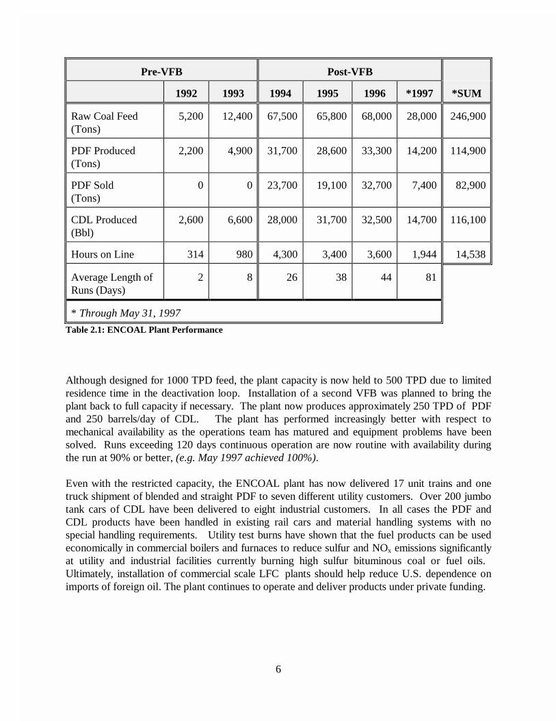
Table 2.1 summarizes the operating experience of the ENCOAL plant. The table is divided intotwo distinct periods; (1) the early runs before installation of the deactivation loop discussed belowwhich concentrated on solving equipment and stabilization problems and (2) runs after the VFBinstallation which were primarily production runs for test burns. As the table clearly shows, theoperating hours for the plant and average length of runs improved markedly after the 1993shutdown due to all the modifications made during the outage, a primary focus of this report.
6
Pre-VFB Post-VFB
1992 1993 1994 1995 1996 *1997 *SUM
Raw Coal Feed(Tons)
5,200 12,400 67,500 65,800 68,000 28,000 246,900
PDF Produced(Tons)
2,200 4,900 31,700 28,600 33,300 14,200 114,900
PDF Sold(Tons)
0 0 23,700 19,100 32,700 7,400 82,900
CDL Produced(Bbl)
2,600 6,600 28,000 31,700 32,500 14,700 116,100
Hours on Line 314 980 4,300 3,400 3,600 1,944 14,538
Average Length ofRuns (Days)
2 8 26 38 44 81
* Through May 31, 1997
Table 2.1: ENCOAL Plant Performance
Although designed for 1000 TPD feed, the plant capacity is now held to 500 TPD due to limitedresidence time in the deactivation loop. Installation of a second VFB was planned to bring theplant back to full capacity if necessary. The plant now produces approximately 250 TPD of PDFand 250 barrels/day of CDL. The plant has performed increasingly better with respect tomechanical availability as the operations team has matured and equipment problems have beensolved. Runs exceeding 120 days continuous operation are now routine with availability duringthe run at 90% or better, (e.g. May 1997 achieved 100%).
Even with the restricted capacity, the ENCOAL plant has now delivered 17 unit trains and onetruck shipment of blended and straight PDF to seven different utility customers. Over 200 jumbotank cars of CDL have been delivered to eight industrial customers. In all cases the PDF andCDL products have been handled in existing rail cars and material handling systems with nospecial handling requirements. Utility test burns have shown that the fuel products can be usedeconomically in commercial boilers and furnaces to reduce sulfur and NOx emissions significantlyat utility and industrial facilities currently burning high sulfur bituminous coal or fuel oils. Ultimately, installation of commercial scale LFC plants should help reduce U.S. dependence onimports of foreign oil. The plant continues to operate and deliver products under private funding.
7
The ENCOAL Project has demonstrated for the first time the integrated operation of severalunique process steps:
• Coal drying on a rotary grate using convective heating• Coal devolatilization on a rotary grate using convective heating• Hot particulate removal with cyclones• Integral solids cooling and deactivation• Combustors operating on low Btu gas from internal streams• Solids stabilization for storage and shipment• Computer control and optimization of a mild coal gasification process• Dust suppressant on PDF solid fuels
3.0 OVERVIEW OF PROCESS
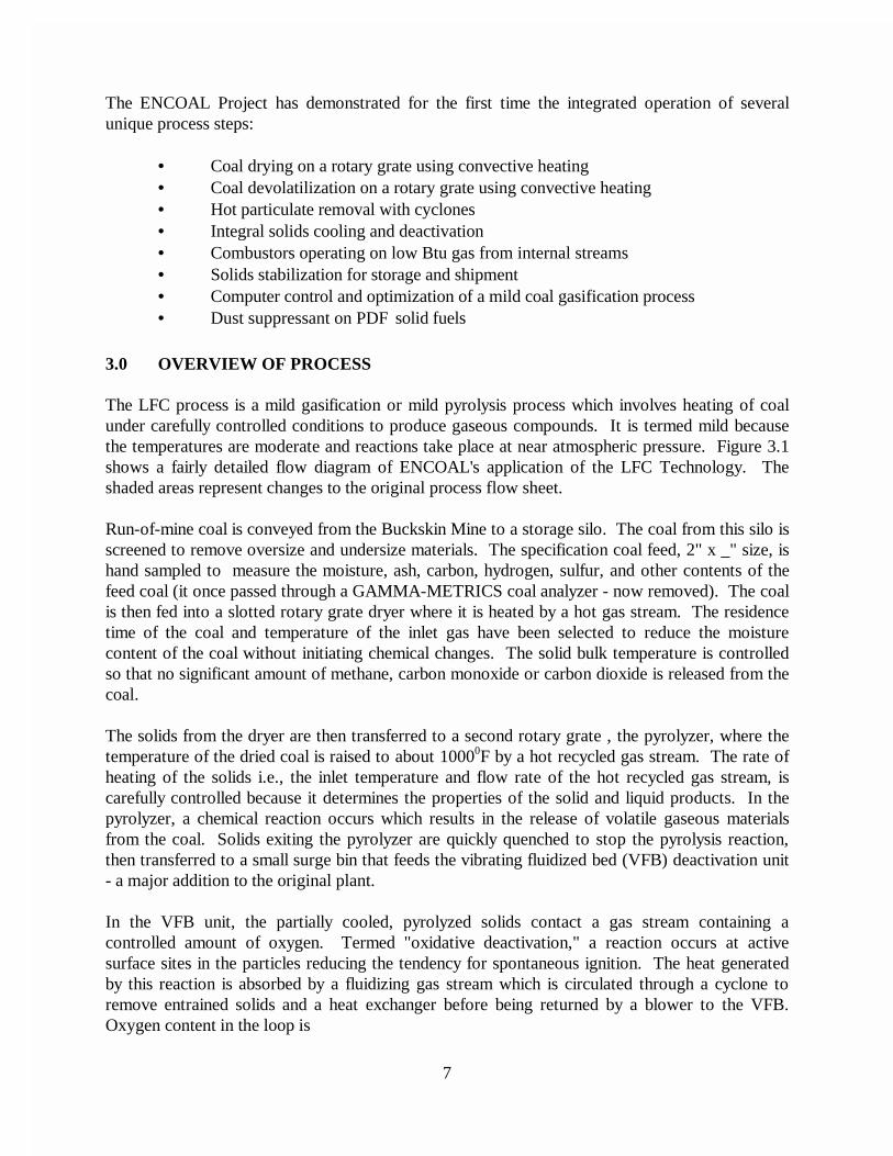
The LFC process is a mild gasification or mild pyrolysis process which involves heating of coalunder carefully controlled conditions to produce gaseous compounds. It is termed mild becausethe temperatures are moderate and reactions take place at near atmospheric pressure. Figure 3.1shows a fairly detailed flow diagram of ENCOAL's application of the LFC Technology. Theshaded areas represent changes to the original process flow sheet.
Run-of-mine coal is conveyed from the Buckskin Mine to a storage silo. The coal from this silo isscreened to remove oversize and undersize materials. The specification coal feed, 2" x _" size, ishand sampled to measure the moisture, ash, carbon, hydrogen, sulfur, and other contents of thefeed coal (it once passed through a GAMMA-METRICS coal analyzer - now removed). The coalis then fed into a slotted rotary grate dryer where it is heated by a hot gas stream. The residencetime of the coal and temperature of the inlet gas have been selected to reduce the moisturecontent of the coal without initiating chemical changes. The solid bulk temperature is controlledso that no significant amount of methane, carbon monoxide or carbon dioxide is released from thecoal.
The solids from the dryer are then transferred to a second rotary grate , the pyrolyzer, where thetemperature of the dried coal is raised to about 10000F by a hot recycled gas stream. The rate ofheating of the solids i.e., the inlet temperature and flow rate of the hot recycled gas stream, iscarefully controlled because it determines the properties of the solid and liquid products. In thepyrolyzer, a chemical reaction occurs which results in the release of volatile gaseous materialsfrom the coal. Solids exiting the pyrolyzer are quickly quenched to stop the pyrolysis reaction,then transferred to a small surge bin that feeds the vibrating fluidized bed (VFB) deactivation unit- a major addition to the original plant.
In the VFB unit, the partially cooled, pyrolyzed solids contact a gas stream containing acontrolled amount of oxygen. Termed "oxidative deactivation," a reaction occurs at activesurface sites in the particles reducing the tendency for spontaneous ignition. The heat generatedby this reaction is absorbed by a fluidizing gas stream which is circulated through a cyclone toremove entrained solids and a heat exchanger before being returned by a blower to the VFB.Oxygen content in the loop is
8
PyrolyzerCombustor
Flue GasDe-Sulfur
Raw Coal
Deactivation
Process GasSol ids
Legend
Cyclone
Screen
CombustorDryer
Blower
Dryer
Pyrolyzer
QuenchCyclone
StorageTo PDF
Cooler
Blower
ESP
Dryer GasLiquids
Recovery
C D L
C D LStorage
To Truck andRail Loadout
Stack
Finisher
Air
Proposed Process Addit ions
Process Addit ions
Original Process
Figure 3.1: Simpli f ied Flow Diagram
9
maintained by introducing the proper amount of air through a control valve. Excess gas in theloop is purged to the dryer combustor for incineration.
Following the VFB, the solids are cooled to near atmospheric temperature in an indirect rotarycooler. A controlled amount of water is added in the rotary cooler to rehydrate the PDF to nearits ASTM equilibrium moisture content. This is also an important step in the stabilization of thePDF. The cooled PDF is then transferred to a storage bin. Because the solids have little or nofree surface moisture and, therefore, are likely to be dusty, a patented dust suppressant called MKis added as PDF leaves the product surge bin.
At the present time, the PDF is not completely stabilized with respect to oxygen upon leaving theplant. The PDF must be "finished" by a short exposure to atmospheric conditions in a layeredstockpile prior to being reclaimed and shipped. In addition to atmospheric stabilized PDF, astable product can be made by blending run-of-plant PDF with either ROM coal or theatmosphere stabilized PDF , but there is a Btu penalty. ENCOAL has recently completed pilot-scale equipment tests that successfully perform this finishing step using continuous processequipment. The design uses commercially available equipment to be installed just downstream ofthe rotary cooler mentioned above, and will effectively stabilize PDF without the layered stockpilestep. Installation of this equipment is currently scheduled for the second half of 1997.
The hot gas produced in the pyrolyzer is sent through a cyclone for removal of the particulatesand then cooled in a quench column to stop any additional pyrolysis reactions and to condense thedesired liquids. Only the CDL is condensed in this step; the condensation of water is avoided. Electrostatic precipitators recover any remaining liquid droplets and mists from the gas leavingthe condensation unit.
Almost half of the residual gas from the liquid recovery unit is recycled directly to the pyrolyzer,while some is first burned in the pyrolyzer combustor before being blended with the recycled gasto provide heat for the mild gasification reaction. The remaining gas is burned in the dryercombustor, which converts sulfur compounds to sulfur oxides. Nitrogen oxide emissions arecontrolled via appropriate design of the combustor. The hot flue gas from the dryer combustor isblended with the recycled gas from the dryer to provide the heat and gas flow necessary fordrying.
The unrecycled portion of the off-gas from the dryer is treated in a wet gas scrubber and ahorizontal scrubber, both using a water-based sodium carbonate solution. The wet gas scrubberrecovers the fine particulates that escape the dryer cyclone, and the horizontal scrubber removesmost of the sulfur oxides from the flue gas. The treated gas is vented to a stack. The spentsolution is discharged into a pond for evaporation. The plant has several utility systems supportingits operation. These include nitrogen, steam, natural gas, compressed air, bulk sodium carbonateand a glycol/water heating and cooling system.
10
4.0 PLANT EQUIPMENT MODIFICATIONS
The early operation of the ENCOAL plant facilities was typical of what would be expected from afirst-of-its-kind technology application. Along with the many successful plant runs there were many more false starts. Valuable information was gained from every run, successful or not, andthis information was carefully evaluated to define necessary equipment repairs, plant modificationsand process adjustments.
In the last five years, numerous changes have been made to the ENCOAL plant facilities as wellas to the computer programs that control its operation. These have taken place both during plantoperation and during shutdowns. Planning for these changes starts during an operating mode ineither case, sometimes involving contractors or operators on overtime making preparations for themodifications in a way that minimizes the length of a planned shutdown. The longest shutdownfor modifications to date occurred from July 1993 to January 1994 for addition of the deactivationloop. Several shorter shutdowns were also required for other less involved modifications, someof which were remote to the main plant and work could proceed without interrupting plantoperations, like the temporary process water handling system. The following sections describethe modifications made to the original plant equipment.
4.1 Solids Handling SystemProblems in the solids handling systems in the ENCOAL plant were self inflicted in someareas, like spillage control. Dribble chutes, space for collection and clean-up and screwconveyors for the fines transfer were neglected in the original design. A means ofremoving raw coal from the feed coal silo without running through the plant becameimportant during an unplanned lengthy shutdown. In the case of the flexible wall vertical plant feed and PDF conveyors (s-belts), the excessive spillage and fluid drive systemsproved very troublesome. The GAMMA-METRICS on-line coal analyzers wereeventually removed because of inferior software, cheap clone computers and a paucity ofmanufacturer’s support. Sampling for the extensive calibration testing needed for theseanalyzers also was a problem because it had to be done by hand. Drag conveyors in theplant, all of the single chain design with hardened flights, have been very high maintenanceitems.
S-belts
The Schultz Flex-O-Wall conveyors furnished with the original plant only had a few inchesof clearance with the floor or nearest enclosure wall. High spillage is inherent because ofthe bucket design. The result was a maximum of a few hours run time before the materialbuilt up under the belts and began to be carried back, a fire hazard and thus causing a plantshutdown. During successive shutdowns, especially the VFB addition, dribble chuteswere added, trenches jack-hammered into the floors and a screw conveyor added toeliminate the problems. The motors and fluid drive clutches ordered with these conveyorswere sized too close to the nominal design and could not handle any surges.Eventuallythe motors were replaced and the fluid drives removed.
11
GAMMA-METRICS Analyzers
The original LFC Technology concept included a closed loop process control scheme thatrelied on rapid, reliable on-line feed coal analysis as well as PDF solid product analysis. GAMMA-METRICS nuclear analyzers were purchased for the plant feed and productstreams at an installed cost of well over $1,400,000. The data from the analyzers was toprovide feed forward and feed backward control of the process variables to allowoptimization of the LFC process. Extensive efforts were made over the first four years ofthe project to calibrate these units so they would provide the needed process information. Hand sampling required for gathering the seemingly endless samples required by themanufacturer made the effort even more difficult.
Numerous 30 to 60 day sampling campaigns on a several-times-per-day basis werecompleted only to be thwarted by software or computer crashes that caused loss of alldata. Plant shutdowns also caused some of the problems, but invariably the userunfriendly data gathering equipment furnished by GAMMA-METRICS would fail beforethe plant could be brought back on line. Manufacturers support was very poor. In the fallof 1996, both GAMMA-METRICS analyzers were removed to end the exorbitant cost ofmaintaining the nuclear sources. Samples of coal and PDF are now taken manually onceper shift and analyzed on site to maintain process checks.
Miscellaneous
To solve the problem of removing raw coal from the storage silo without going throughthe plant, a by-pass chute was added in the screening building. In retrospect, this shouldbe included with any PRB storage unit to handle hot coal or avoid potentially long storagetimes. A dribble chute was also added on the plant feed belt to catch spillage. Otherdribble chutes, wear plates, flow diverters and cleanout doors were also added in severalplaces. Today the system operates very well. The drag conveyors still are highmaintenance but money and time has not been available to change them to the dual chaindesign that would be much more reliable (and costly to buy). Drag conveyors in general,and certainly single chain type, should be avoided in commercial plants.
4.2 Dryer and Pyrolyzer Modifications
Dryer and Pyrolyzer Internal Seals
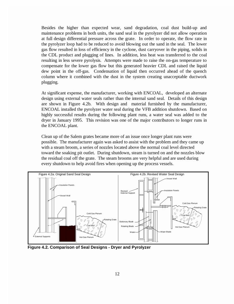
ENCOAL's process uses convective heating in the Salem Furnace Company rabbled rotaryhearth furnaces for the dryer and pyrolyzer units. This is accomplished by passing hotgasses through a slotted, rotating grate upon which rests a bed of coal. The seal betweenthe rotating grate and the vessel wall, which prevents the hot gas below the grate frombypassing the coal bed, was a blade attached to the rotating member immersed in astationary tub of sand. See Figure 4.2a for the details. This seal design proved to be verytroublesome.
12
Besides the higher than expected wear, sand degradation, coal dust build-up andmaintenance problems in both units, the sand seal in the pyrolyzer did not allow operationat full design differential pressure across the grate. In order to operate, the flow rate inthe pyrolyzer loop had to be reduced to avoid blowing out the sand in the seal. The lowergas flow resulted in loss of efficiency in the cyclone, dust carryover in the piping, solids inthe CDL product and plugging of lines. In addition, less heat was transferred to the coalresulting in less severe pyrolysis. Attempts were made to raise the on-gas temperature tocompensate for the lower gas flow but this generated heavier CDL and raised the liquiddew point in the off-gas. Condensation of liquid then occurred ahead of the quenchcolumn where it combined with the dust in the system creating unacceptable ductworkplugging.
At significant expense, the manufacturer, working with ENCOAL, developed an alternatedesign using external water seals rather than the internal sand seal. Details of this designare shown in Figure 4.2b. With design and material furnished by the manufacturer,ENCOAL installed the pyrolyzer water seal during the VFB addition shutdown. Based onhighly successful results during the following plant runs, a water seal was added to thedryer in January 1995. This revision was one of the major contributors to longer runs inthe ENCOAL plant.
Clean up of the Salem grates became more of an issue once longer plant runs werepossible. The manufacturer again was asked to assist with the problem and they came upwith a steam broom, a series of nozzles located above the normal coal level directedtoward the soaking pit outlet. During shutdown, steam is turned on and the nozzles blowthe residual coal off the grate. The steam brooms are very helpful and are used duringevery shutdown to help avoid fires when opening up the process vessels.
Figure 4.2. Com parison of Seal Desi gns - Dr yer and P yrol yzer
Figure 4.2b. Revised Water Seal DesignFigure 4.2a. Original Sand Seal Design
Wiper BladeWater
Rotating Blade
Stationary Blade
External SupportRevised Insulation Panels
Vessel Wall
Cold Gas Plenum
Coal Bed
Rotating Grate
Hot Gas PlenumSand
Hot Gas Plenum
Rotating Grate
Coal Bed
Cold Gas Plenum
External Supports
Vessel Wall
Insulation Panels
13
In addition, a steam blaster was added to both units that swings down near the grate toclean the slots in the grate without entering the dryer or pyrolyzer. These have been usedsuccessfully to extend a run when the plugging of the grates is moderate. Manual cleaningis still required after many months of operation. This buildup is not a major problem. It iseasily removed, consisting mostly of coal dust, not coke. It can be handled during normalyearly turnarounds in a commercial plant.
4.3 Dryer and Pyrolyzer Cyclones
Dryer Cyclone
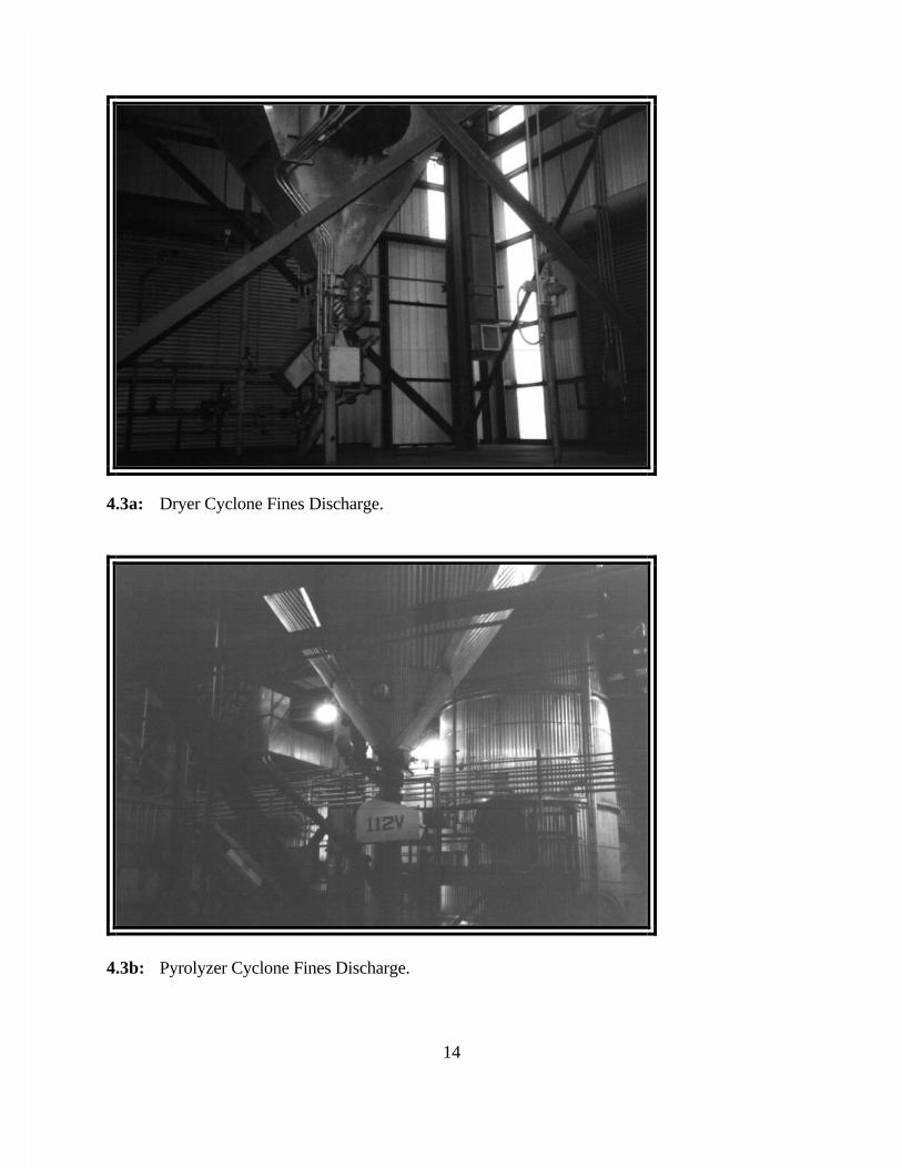
Operation of the dryer cyclone was very successful with no modifications being made tothe cyclone itself. However, the fines handling system at the discharge of the unit wassignificantly changed. The original design included indirect heat exchange via a screwcooler prior to being slurried to the sump system. Because of maintenance and pluggingproblems with the screw cooler, this unit was removed. The final layout simply mixes thefines with water immediately under the rotary valve airlock prior to draining to the plantsump system. (See Figure 4.3a: Dryer Cyclone Fines Discharge)
Pyrolyzer Cyclone
Operation of the pyrolyzer cyclone was not as successful as the dryer. The pyrolyzercyclone was originally designed to be 97% efficient; however, problems with limited loopflow rates, cyclone pressure drop, and the small size and quantity of fines made thiscyclone only 75% efficient. The pyrolyzer water seal modification discussed earlier didallow for higher flowrates and pressure drop, but the cyclone still did not perform asdesigned. This resulted in high sediment concentrations in the CDL. The gas inlet and thevortex finder were then modified to aid in flow direction and pressure drop increase. These modifications were somewhat successful yielding a CDL with an average sedimentof 3 wt%. Although not 97% efficient, the pyrolyzer cyclone operation is now acceptable.
Other modifications to the pyrolyzer cyclone include extensive changes to the fineshandling system. The fines slurry mix tank and pump system originally designed forhandling the pyrolyzer cyclone fines continually plugged and experienced high wear. Thissystem was therefore removed. Like the dryer cyclone, the present fines handling systemis a simple water-fines mixing box immediately under the rotary airlock prior to gravitydraining to the sump system. This arrangement is easy to maintain and does not utilizeany motorized equipment to operate. (See Figure 4.3b: Pyrolyzer Cyclone FinesDischarge)
14
4.3a: Dryer Cyclone Fines Discharge.
4.3b: Pyrolyzer Cyclone Fines Discharge.
15
4.4 Pyrolyzer Quench Table and Quench Steam Condensing System
Pyrolyzer Quench Table
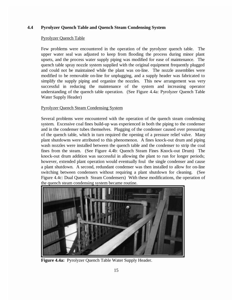
Few problems were encountered in the operation of the pyrolyzer quench table. Theupper water seal was adjusted to keep from flooding the process during minor plantupsets, and the process water supply piping was modified for ease of maintenance. Thequench table spray nozzle system supplied with the original equipment frequently pluggedand could not be maintained while the plant was on-line. The nozzle assemblies weremodified to be removable on-line for unplugging, and a supply header was fabricated tosimplify the supply piping and organize the nozzles. This new arrangement was verysuccessful in reducing the maintenance of the system and increasing operatorunderstanding of the quench table operation. (See Figure 4.4a: Pyrolyzer Quench TableWater Supply Header)
Pyrolyzer Quench Steam Condensing System
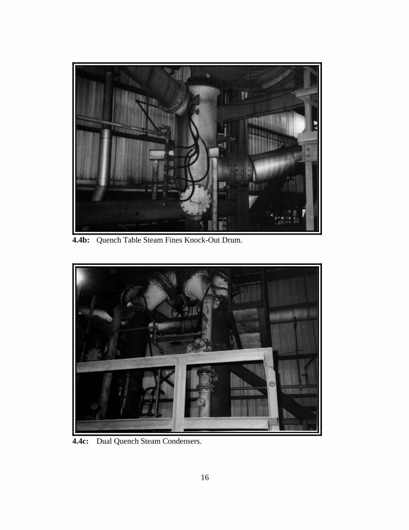
Several problems were encountered with the operation of the quench steam condensingsystem. Excessive coal fines build-up was experienced in both the piping to the condenserand in the condenser tubes themselves. Plugging of the condenser caused over pressuringof the quench table, which in turn required the opening of a pressure relief valve. Manyplant shutdowns were attributed to this phenomenon. A fines knock-out drum and pipingwash nozzles were installed between the quench table and the condenser to strip the coalfines from the steam. (See Figure 4.4b: Quench Steam Fines Knock-out Drum) Theknock-out drum addition was successful in allowing the plant to run for longer periods;however, extended plant operation would eventually foul the single condenser and causea plant shutdown. A second, redundant condenser was then installed to allow for on-lineswitching between condensers without requiring a plant shutdown for cleaning. (SeeFigure 4.4c: Dual Quench Steam Condensers) With these modifications, the operation ofthe quench steam condensing system became routine.
Figure 4.4a: Pyrolyzer Quench Table Water Supply Header.
16
4.4b: Quench Table Steam Fines Knock-Out Drum.
4.4c: Dual Quench Steam Condensers.
17
4.5 PDF Deactivation System
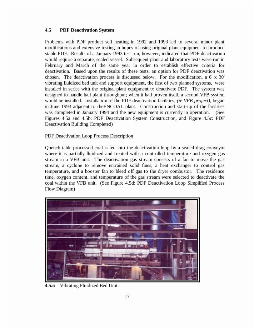
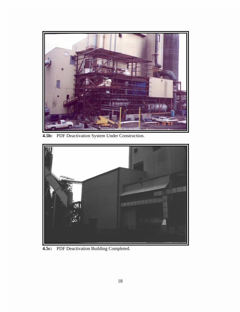
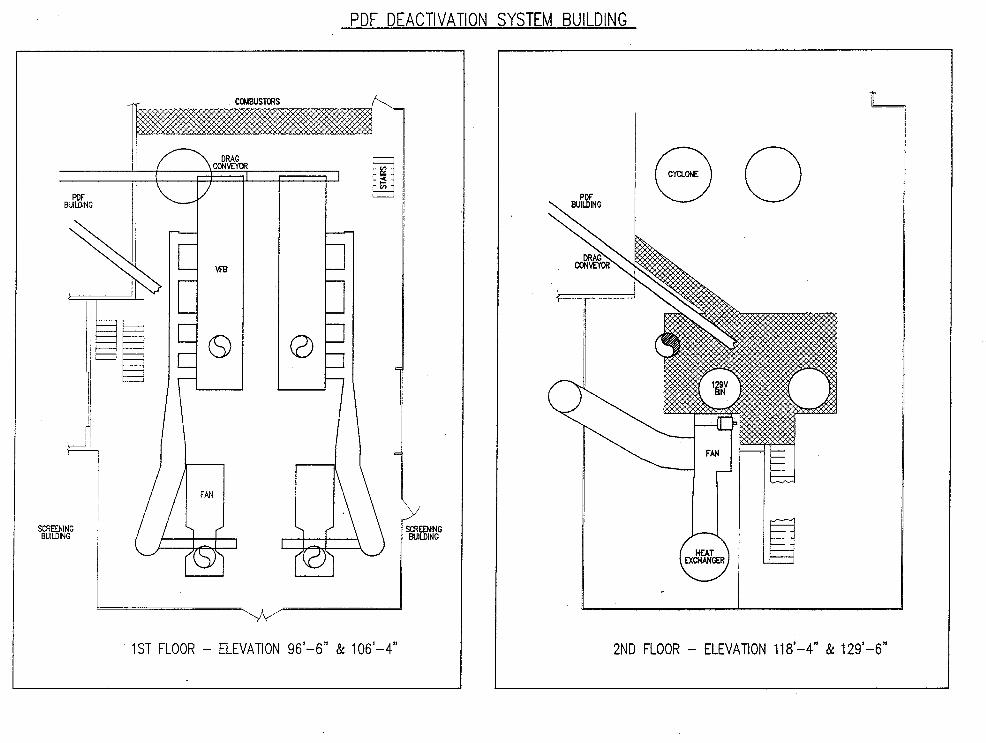
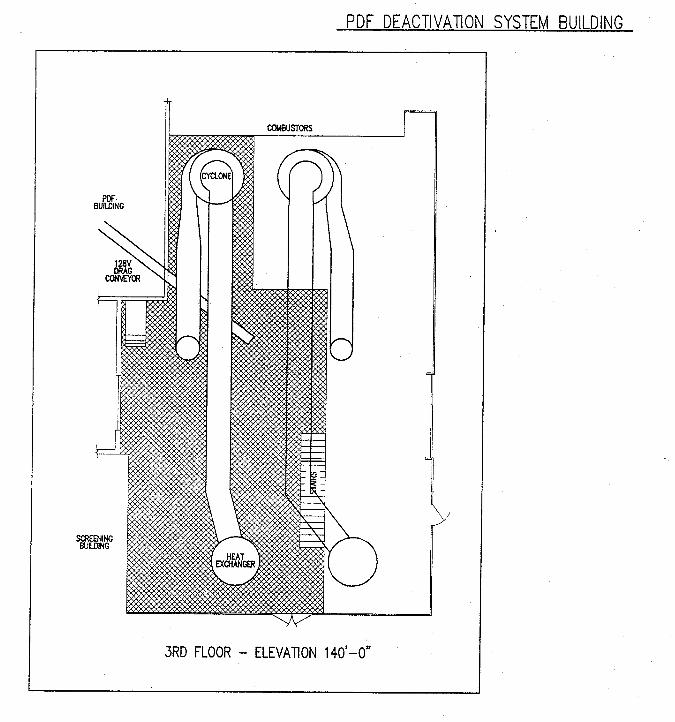
Problems with PDF product self heating in 1992 and 1993 led to several minor plantmodifications and extensive testing in hopes of using original plant equipment to producestable PDF. Results of a January 1993 test run, however, indicated that PDF deactivationwould require a separate, sealed vessel. Subsequent plant and laboratory tests were run inFebruary and March of the same year in order to establish effective criteria fordeactivation. Based upon the results of these tests, an option for PDF deactivation waschosen. The deactivation process is discussed below. For the modification, a 6' x 30'vibrating fluidized bed unit and support equipment, the first of two planned systems, wereinstalled in series with the original plant equipment to deactivate PDF. The system wasdesigned to handle half plant throughput; when it had proven itself, a second VFB systemwould be installed. Installation of the PDF deactivation facilities, (ie VFB project), beganin June 1993 adjacent to theENCOAL plant. Construction and start-up of the facilitieswas completed in January 1994 and the new equipment is currently in operation. (SeeFigures 4.5a and 4.5b: PDF Deactivation System Construction, and Figure 4.5c: PDFDeactivation Building Completed)
PDF Deactivation Loop Process Description
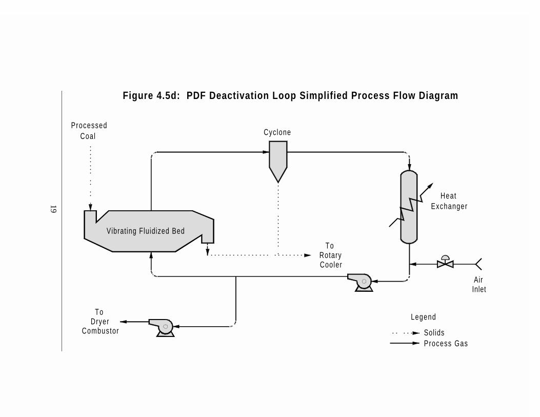
Quench table processed coal is fed into the deactivation loop by a sealed drag conveyorwhere it is partially fluidized and treated with a controlled temperature and oxygen gasstream in a VFB unit. The deactivation gas stream consists of a fan to move the gasstream, a cyclone to remove entrained solid fines, a heat exchanger to control gastemperature, and a booster fan to bleed off gas to the dryer combustor. The residencetime, oxygen content, and temperature of the gas stream were selected to deactivate thecoal within the VFB unit. (See Figure 4.5d: PDF Deactivation Loop Simplified ProcessFlow Diagram)
4.5a: Vibrating Fluidized Bed Unit.
18
4.5b: PDF Deactivation System Under Construction.
4.5c: PDF Deactivation Building Completed.
19
Cyclone
HeatExchanger
InletAir
Legend
SolidsProcess Gas
RotaryTo
Cooler
Vibrating Fluidized Bed
CoalProcessed
CombustorDryer
To
Figure 4.5d: PDF Deactivation Loop Simplified Process Flow Diagram
20
VFB System Operation
By the spring of 1994, plant production runs were considerably smoother and longer. The new deactivation system allowed for shipment of PDF to utility customers for thefirst time; however, even as PDF stability was notably improved with the addition of theVFB, deactivation of PDF still required additional oxygen prior to shipment. Over 20different operating conditions were varied and evaluated to enhance the amount of oxygenabsorbed in the VFB system, but were not entirely successful. The decision was made to“finish” the oxidation deactivation of the solids by laying the PDF on the ground outsidethe plant. This process, which came to be known as “pile layering”, involves spreading thePDF in 12-inch layers thus allowing PDF particles to react with oxygen and becomestable. As each thickness is stabilized, more PDF may be layered on top. This method ofstabilization, (combined with blending with ROM coal, increased silo retention times, andslightly higher rehydration rates), has been used to deactivate PDF for all shipments todate.
In-plant stabilization of PDF, however, still required more evaluation. This evaluationprocess was conducted in 1995 and 1996 in series with the plant operation, and discussionof this work is found below in Section 4.14: PDF Finishing.
4.6 PDF Cooler and Rehydration
The cooler is a rotating cylindrical vessel which measures 11 feet diameter and 50 feet inlength, and is used to cool PDF to atmospheric temperature in the LFC Process. The unitindirectly cools the PDF using internal cooling water tubes and tumbling action toaccomplish the heat exchange. This unit was found to be a very efficient heat exchanger,and little mechanical or operating problems were encountered. In fact, concerns ofexternal tube fouling with dust were alleviated as the tumbling action of the PDF kept thetube surfaces clean during operation.
Several temporary modifications were made to the PDF cooler in late 1992 in an effort toimprove PDF stability using in-plant equipment. These modifications included theaddition of a fan, ductwork, and entrained fines removal equipment to circulate acontrolled oxygen atmosphere through the cooler. These modifications provedunsuccessful, and it was determined that a separate, sealed vessel would be required todeactivate PDF as discussed in Section 4.5 above. The gas circulation system wastherefore removed from the cooler.
Rehydration
Other modifications made to the unit, however, were more successful. The original designof the ENCOAL plant placed the rehydration step in the process at the top of the PDFsilo, spraying water on the PDF as it dropped vertically into storage. This rehydrationtechnique proved to be inconsistent as it was difficult to obtain uniform distribution of
21
water on the PDF, and there was not adequate mixing as PDF entered the silo. Inaddition, as PDF rehydrates to equilibrium moisture, the resulting heat of reactionnecessitates heat removal, or the PDF overheats and becomes unstable.
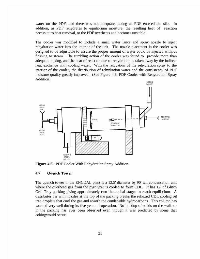
The cooler was modified to include a small water lance and spray nozzle to injectrehydration water into the interior of the unit. The nozzle placement in the cooler wasdesigned to be adjustable to ensure the proper amount of water could be injected withoutflashing to steam. The tumbling action of the cooler was found to provide more thanadequate mixing, and the heat of reaction due to rehydration is taken away by the indirectheat exchange with cooling water. With the relocation of the rehydration spray to theinterior of the cooler, the distribution of rehydration water and the consistency of PDFmoisture quality greatly improved. (See Figure 4.6: PDF Cooler with Rehydration SprayAddition)
COOLINGWATERINLET
OUTLETWATER
COOLING
REHYDRATEDPROCESS
COAL OUTLET
COAL INLETPROCESSED
REHYDRATIONWATER INLET
SPRAY NOZZLE
ROTATION
REHYDRATION
M
Figure 4.6: PDF Cooler With Rehydration Spray Addition.
4.7 Quench Tower
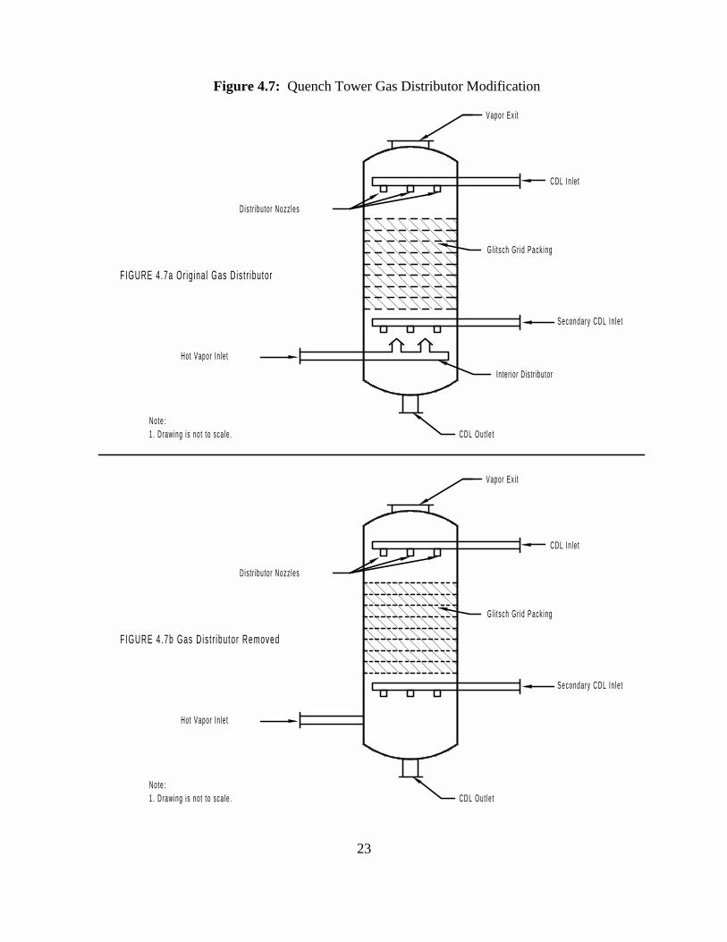
The quench tower in the ENCOAL plant is a 12.5' diameter by 90' tall condensation unitwhere the overhead gas from the pyrolyzer is cooled to form CDL. It has 12' of GlitchGrid Tray packing giving approximately two theoretical stages to reach equilibrium. Adistributer bar with nozzles at the top of the packing breaks the refluxed CDL cooling oilinto droplets that cool the gas and absorb the condensible hydrocarbons. This column hasworked very well during its five years of operation. No buildup of solids on the walls orin the packing has ever been observed even though it was predicted by some thatcokingwould occur.
22
One problem did occur in the column inlet piping and gas distributor. An oily mixture ofcoal fines and heavy pitch would build up at the column inlet distributor as shown inFigure 4.7a. This accumulation caused several plant shutdowns and many hours ofcleanup in the piping, (and general area when the oils were inadvertently spilled). Afterseveral attempts to make larger and larger weep holes work in the distributor, it wascompletely removed. The revised distributor is depicted in Figure 4.7b has eliminated theproblem and the plant has operated for nearly two years without measurable buildup. Inthe preceding two years the piping had to be cleaned out about every three months.
4.8 Electrostatic Precipitators
Much time was spent in repairing the ESP's in 1992 and 1993. Numerous plantshutdowns were caused by failed insulators in all three units. ENCOAL worked inconjunction with the ESP manufacturer to establish the cause of the insulator failures. Asa result of this effort, several modifications were implemented and are listed as follows:
1) New non-glazed, ceramic insulators were fabricated and installed in theunits. These new insulators are made of a material that is resistant tocracking and are of a slightly different design than the originals.
2) Heating blankets and external insulation were added on the insulator cansand the blankets were set to a temperature that maintain 250oF at theinsulator. The high temperatures keep the surface of the insulator hot anddo not allow liquids to condense on the insulator surface.
3) Thermocouples were installed on all of the insulator cans to monitor thecan temperature during plant operation. An operator alarm is activated ifthe can temperature falls below the set temperature.
4) The gas flows through the three ESP units were balanced. A balanced flowensures that process gas is distributed equally and not concentratedthrough one ESP.
5) A nitrogen purge was added to all insulator mounts to keep CDL fromcondensing on the insulator surface, and thereby avoiding an insulatorfailure.
These modifications were very successful in solving the operational difficulties with theESP's. Once the initial insulator failures were overcome, the ESP's operated very well forthe remaining 3½ years of operation.
23
Figure 4.7: Quench Tower Gas Distributor Modification
Vapor Ex i t
CDL In le t
G l i t sch Gr id Pack ing
Secondary CDL In le t
CDL Out le t
Hot Vapor In le t
Note :1 . Drawing is not to sca le .
F IGURE 4.7b Gas Dis t r ibu tor Removed
Dist r ibutor Nozz les
Inter ior Distr ibutor
Dis t r ibutor Nozz les
FIGURE 4.7a Or ig ina l Gas Dis t r ibutor
1. Drawing is not to sca le .Note :
Hot Vapor In le t
CDL Out le t
Secondary CDL In le t
G l i t sch Gr id Pack ing
CDL In le t
Vapor Ex i t
24
4.9 CDL Handling and Storage
Essentially no modifications were made to the original CDL handling and storage systems withthe exception of the loadout facilities. The CDL loadout flow meter was removed afterloading the first rail car. The meter fouled with CDL and became inoperable. It was decidedthat maintenance of this instrument would be high and a system of tank car measurement andweighing of the cars was utilized for all further shipments. The loadout pump was alsorelocated from the loadout area to the CDL storage tank. Insufficient suction head of thepump necessitated its relocation to be closer to the main storage tank. Overall, the CDLhandling system operated quite well and was one of the least modified systems in the plant. Inparticular, the glycol/water heat tracing of the CDL lines proved to be ideal even during theextreme winter temperatures of Wyoming. The CDL system could be started from a "cold"stop, with little or no impact on the system operation.
Independent of the plant operation, sediment removal from CDL was tested in late 1996 in anattempt to reduce the solids content of the oil and expand CDL market opportunities. A smallcentrifuge was installed and tested at various conditions. From these tests, it was determinedthat a centrifuge could be used to remove 95% of the sediment with less than a 5% loss ofCDL by weight. A conceptual design was made to implement a CDL solids removal systemusing the results of this test. The system would consist of a feed surge tank, pump, and acentrifuge to handle the CDL, and a fines bin, mixer, and a pelletizer to handle the sludgegenerated by the removed solids. Dryer or pyrolyzer cyclone fines can be blended with thesludge and agglomerated to produce a pellet PDF product. This agglomeration step wastested in early 1997, and fines to sludge ratios of 85% to 15% were successful in producing anacceptable pellet. Further CDL solids removal testing is ongoing and implementation of a full-scale system depends on market response to the "cleaned" CDL.
4.10 Process Fans
Both the dryer and the pyrolyzer fans were found to operate acceptably as designed for theprocess flow and temperature conditions, but were grossly inadequate in terms of sealing theprocess gases. In both units, the casing gaskets were replaced, and the casings themselves hadto be modified and seal welded in the field to correct poor quality fabrication. The vendorsupplied shaft seals were also found to be inadequate. Major modifications were made to thedryer fan in particular to accommodate a new mechanical carbon gland seal on a casing thatwas not designed to be gas tight. Once installed, the new carbon seals were more effective,but would eventually leak due to accelerated wear by fines in the process gas. Even withnitrogen purges, the fines in the process gas would contaminate the seal surface andexcessively wear the carbon rings after only a few weeks of operation. Several iterations weremade on sealing the units, and finally an ENCOAL "home-made" packing gland type seal withhigh temperature grease was found to be the best and longest lasting seal. Today, a carbongland seal with a nitrogen purge is used on the suction side of the fan and a packing gland-grease seal is used on the pressure side.
25
4.11 Combustors
Control of the combustors was found to be difficult during start-up. The combination ofoxygen excursions in the dryer loop and oscillation of the air to fuel ratios plagued theoperation. In particular, the transition from secondary air to primary air in the combustorramping sequence was not smooth. The original design primary air control valves did notregulate flows well under low flow conditions. Once the combustors were ramped pastthe transition point, the air control would improve, but the fuel to air ratios wouldfluctuate. An eight inch trim control valve was therefore added to both the pyrolyzer anddryer primary air intakes, and much improved stability of the combustor air flows wasobtained. Programming changes were also made to both combustors that allowed naturalgas flow to follow the combustion air flow rates. This change was necessary to dampenoscillations and prevent oxygen excursions due to improper air to fuel ratios.
Since the initial control problems were overcome, operation of the combustors has beengenerally uneventful. Minor adjustments to the programming occurred during theremaining 4½ years of use, and the combustion of the 30-50 Btu/scf plant recycle gas wasvery successful.
4.12 Purge Gas Treatment
The sodium carbonate solution sulfur recovery scrubber system in use at the ENCOALplant is another system that has worked very well and has not required majormodifications. This system first uses a venturi scrubber of the same patented design as thedust scrubbers to remove particulates from the purge gas stream. A Kellogg patented wetgas scrubber with three water curtains follows the venturi. Sodium carbonate solutionused in both scrubbers removes 97% or more of the sulfur compounds in the purge gasstream.
Because the scrubber system is handling water, SO2 and SO3 at temperatures well belowthe dew point of sulfuric acid, the material of construction selected was fiberglassreinforced plastic. The temperature limit for this material is 170° F. To protect the purgegas piping water sprays were added ahead of the venturi scrubber with firewater backup toinsure they would work. In addition, to provide over temperature protection to the wholedryer loop, an emergency cooling water spray system was added in the dryer on-gasductwork. These systems have performed very well and no purge gas equipment has everbeen damaged, or subjected to temperatures exceeding design.
4.13 Dust Scrubbers
Operation of the original two raw coal dust scrubbers proved that the patented design of these units worked very well to collect dust from conveyor transfer points. However,during start-up and shutdown conditions, there are times when the facilities are notoperating at design conditions, and dried, underpyrolyzed coal (off-spec PDF) is
26
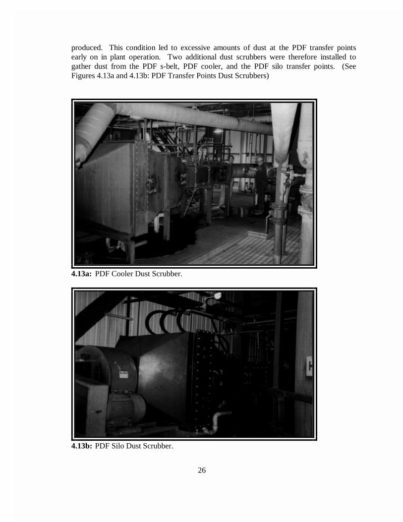
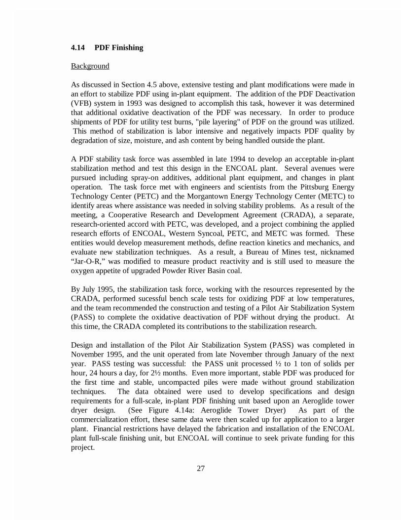
produced. This condition led to excessive amounts of dust at the PDF transfer pointsearly on in plant operation. Two additional dust scrubbers were therefore installed togather dust from the PDF s-belt, PDF cooler, and the PDF silo transfer points. (SeeFigures 4.13a and 4.13b: PDF Transfer Points Dust Scrubbers)
4.13a: PDF Cooler Dust Scrubber.
4.13b: PDF Silo Dust Scrubber.
27
4.14 PDF Finishing
Background
As discussed in Section 4.5 above, extensive testing and plant modifications were made inan effort to stabilize PDF using in-plant equipment. The addition of the PDF Deactivation(VFB) system in 1993 was designed to accomplish this task, however it was determinedthat additional oxidative deactivation of the PDF was necessary. In order to produceshipments of PDF for utility test burns, "pile layering" of PDF on the ground was utilized. This method of stabilization is labor intensive and negatively impacts PDF quality bydegradation of size, moisture, and ash content by being handled outside the plant.
A PDF stability task force was assembled in late 1994 to develop an acceptable in-plantstabilization method and test this design in the ENCOAL plant. Several avenues werepursued including spray-on additives, additional plant equipment, and changes in plantoperation. The task force met with engineers and scientists from the Pittsburg EnergyTechnology Center (PETC) and the Morgantown Energy Technology Center (METC) toidentify areas where assistance was needed in solving stability problems. As a result of themeeting, a Cooperative Research and Development Agreement (CRADA), a separate,research-oriented accord with PETC, was developed, and a project combining the appliedresearch efforts of ENCOAL, Western Syncoal, PETC, and METC was formed. Theseentities would develop measurement methods, define reaction kinetics and mechanics, andevaluate new stabilization techniques. As a result, a Bureau of Mines test, nicknamed“Jar-O-R,” was modified to measure product reactivity and is still used to measure theoxygen appetite of upgraded Powder River Basin coal.
By July 1995, the stabilization task force, working with the resources represented by theCRADA, performed sucessful bench scale tests for oxidizing PDF at low temperatures,and the team recommended the construction and testing of a Pilot Air Stabilization System(PASS) to complete the oxidative deactivation of PDF without drying the product. Atthis time, the CRADA completed its contributions to the stabilization research.
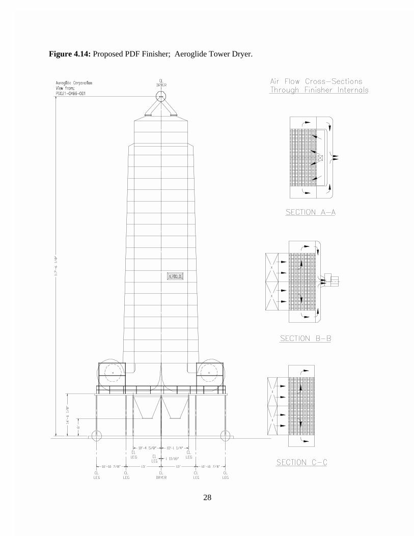
Design and installation of the Pilot Air Stabilization System (PASS) was completed inNovember 1995, and the unit operated from late November through January of the nextyear. PASS testing was successful: the PASS unit processed ½ to 1 ton of solids perhour, 24 hours a day, for 2½ months. Even more important, stable PDF was produced forthe first time and stable, uncompacted piles were made without ground stabilizationtechniques. The data obtained were used to develop specifications and designrequirements for a full-scale, in-plant PDF finishing unit based upon an Aeroglide towerdryer design. (See Figure 4.14a: Aeroglide Tower Dryer) As part of thecommercialization effort, these same data were then scaled up for application to a largerplant. Financial restrictions have delayed the fabrication and installation of the ENCOALplant full-scale finishing unit, but ENCOAL will continue to seek private funding for thisproject.
28
Figure 4.14: Proposed PDF Finisher; Aeroglide Tower Dryer.
29
5.0 PLANT UTILITY MODIFICATIONS
In most cases, the original ENCOAL plant utility systems required few modifications during thelast 5 years of operation. Systems such as glycol/water, natural gas, potable water, and firewaterwere essentially unchanged from the original design. In other cases however, changes werenecessary to make a system more reliable and easier to operate. Utility modifications tookadvantage of plant shutdowns whenever possible, involving contractors or plant operators forimplementation. The longest plant shutdown for utility modifications to date occurred from mid-March 1995 to May 1995 for the addition of the permanent process water fines removal system. Several shorter shutdowns were also required for other less involved modifications, some ofwhich were remote to the main plant and work could proceed without interrupting plantoperations. The following sections describe the changes made to specific plant utility systems.
5.1 Nitrogen
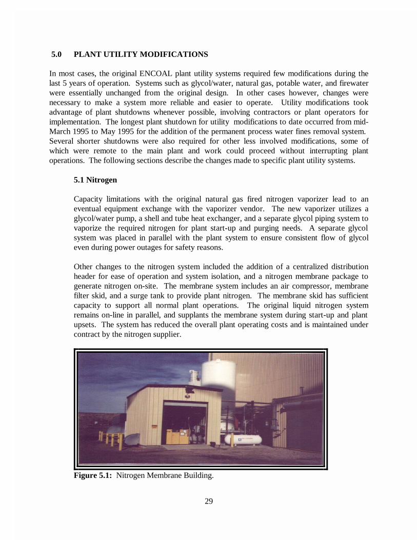
Capacity limitations with the original natural gas fired nitrogen vaporizer lead to aneventual equipment exchange with the vaporizer vendor. The new vaporizer utilizes aglycol/water pump, a shell and tube heat exchanger, and a separate glycol piping system tovaporize the required nitrogen for plant start-up and purging needs. A separate glycolsystem was placed in parallel with the plant system to ensure consistent flow of glycoleven during power outages for safety reasons.
Other changes to the nitrogen system included the addition of a centralized distributionheader for ease of operation and system isolation, and a nitrogen membrane package togenerate nitrogen on-site. The membrane system includes an air compressor, membranefilter skid, and a surge tank to provide plant nitrogen. The membrane skid has sufficientcapacity to support all normal plant operations. The original liquid nitrogen systemremains on-line in parallel, and supplants the membrane system during start-up and plantupsets. The system has reduced the overall plant operating costs and is maintained undercontract by the nitrogen supplier.
Figure 5.1: Nitrogen Membrane Building.
30
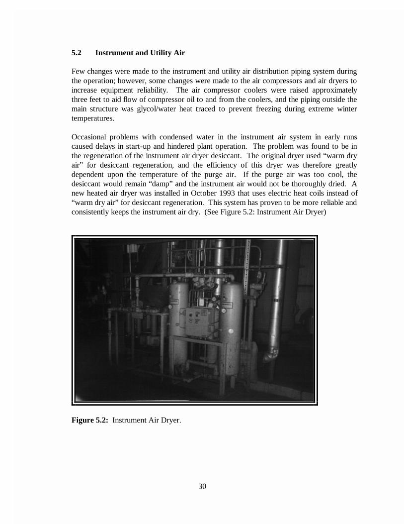
5.2 Instrument and Utility Air
Few changes were made to the instrument and utility air distribution piping system duringthe operation; however, some changes were made to the air compressors and air dryers toincrease equipment reliability. The air compressor coolers were raised approximatelythree feet to aid flow of compressor oil to and from the coolers, and the piping outside themain structure was glycol/water heat traced to prevent freezing during extreme wintertemperatures.
Occasional problems with condensed water in the instrument air system in early runscaused delays in start-up and hindered plant operation. The problem was found to be inthe regeneration of the instrument air dryer desiccant. The original dryer used “warm dryair” for desiccant regeneration, and the efficiency of this dryer was therefore greatlydependent upon the temperature of the purge air. If the purge air was too cool, thedesiccant would remain “damp” and the instrument air would not be thoroughly dried. Anew heated air dryer was installed in October 1993 that uses electric heat coils instead of“warm dry air” for desiccant regeneration. This system has proven to be more reliable andconsistently keeps the instrument air dry. (See Figure 5.2: Instrument Air Dryer)
Figure 5.2: Instrument Air Dryer.
31
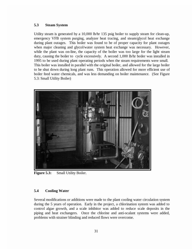
5.3 Steam System
Utility steam is generated by a 10,000 lb/hr 135 psig boiler to supply steam for clean-up,emergency VFB system purging, analyzer heat tracing, and steam/glycol heat exchangeduring plant outages. This boiler was found to be of proper capacity for plant outageswhen major cleaning and glycol/water system heat exchange was necessary. However,while the plant was on-line, the capacity of the boiler was too large for the light steamduty, causing the boiler to cycle excessively. A second 1,000 lb/hr boiler was installed in1995 to be used during plant operating periods when the steam requirements were small. This boiler was installed in parallel with the original boiler, and allowed for the large boilerto be shut down during long plant runs. This operation allowed for more efficient use ofboiler feed water chemicals, and was less demanding on boiler maintenance. (See Figure5.3: Small Utility Boiler)
Figure 5.3: Small Utility Boiler.
5.4 Cooling Water
Several modifications or additions were made to the plant cooling water circulation systemduring the 5 years of operation. Early in the project, a chlorination system was added tocontrol algae growth, and a scale inhibitor was added to reduce scale deposits in thepiping and heat exchangers. Once the chlorine and anti-scalant systems were added,problems with strainer blinding and reduced flows were overcome.
32
As major plant equipment was added to the ENCOAL plant, such as the PDF deactivationand process water fines removal systems, additional demands were placed on the coolingwater system. In order to increase overall cooling water flows, the impellers in the maincooling water pumps were exchanged for larger diameter models in 1993. These pumpswere modified again in 1995, increasing the impeller size and repowering from 75 hp to100 hp. These two changes almost doubled the flow rate capacity of the pumps, andallowed for proper cooling water supply for all the present day plant needs.
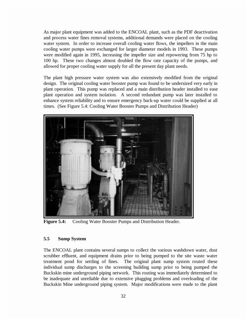
The plant high pressure water system was also extensively modified from the originaldesign. The original cooling water booster pump was found to be undersized very early inplant operation. This pump was replaced and a main distribution header installed to easeplant operation and system isolation. A second redundant pump was later installed toenhance system reliability and to ensure emergency back-up water could be supplied at alltimes. (See Figure 5.4: Cooling Water Booster Pumps and Distribution Header)
Figure 5.4: Cooling Water Booster Pumps and Distribution Header.
5.5 Sump System
The ENCOAL plant contains several sumps to collect the various washdown water, dustscrubber effluent, and equipment drains prior to being pumped to the site waste watertreatment pond for settling of fines. The original plant sump system routed theseindividual sump discharges to the screening building sump prior to being pumped theBuckskin mine underground piping network. This routing was immediately determined tobe inadequate and unreliable due to extensive plugging problems and overloading of theBuckskin Mine underground piping system. Major modifications were made to the plant
33
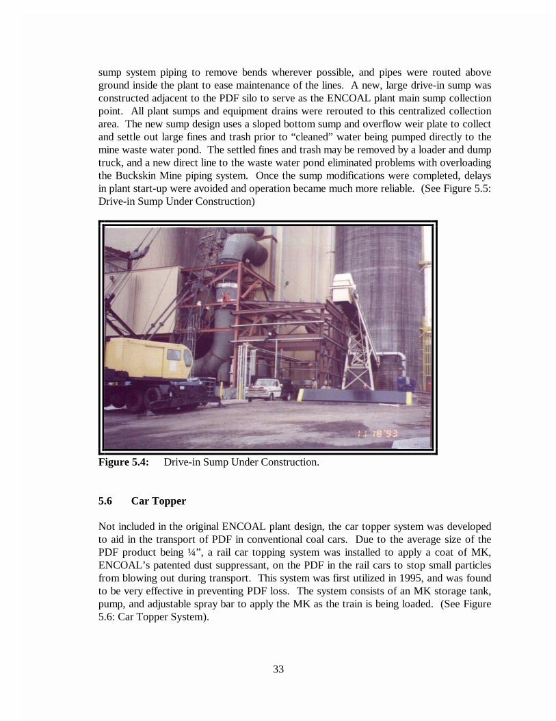
sump system piping to remove bends wherever possible, and pipes were routed aboveground inside the plant to ease maintenance of the lines. A new, large drive-in sump wasconstructed adjacent to the PDF silo to serve as the ENCOAL plant main sump collectionpoint. All plant sumps and equipment drains were rerouted to this centralized collectionarea. The new sump design uses a sloped bottom sump and overflow weir plate to collectand settle out large fines and trash prior to “cleaned” water being pumped directly to themine waste water pond. The settled fines and trash may be removed by a loader and dumptruck, and a new direct line to the waste water pond eliminated problems with overloadingthe Buckskin Mine piping system. Once the sump modifications were completed, delaysin plant start-up were avoided and operation became much more reliable. (See Figure 5.5:Drive-in Sump Under Construction)
Figure 5.4: Drive-in Sump Under Construction.
5.6 Car Topper
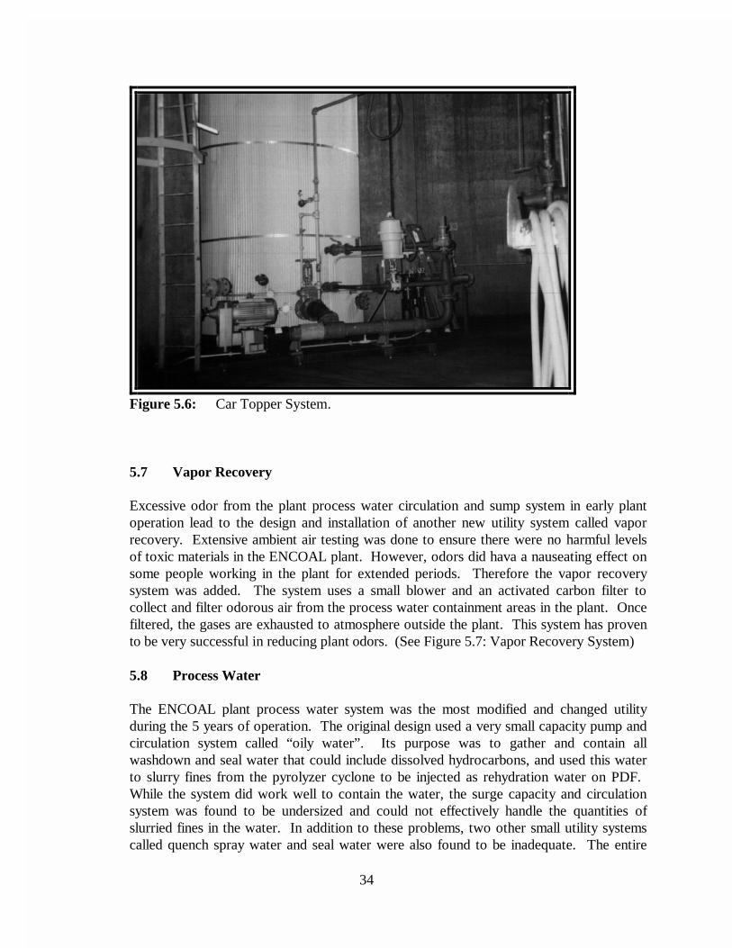
Not included in the original ENCOAL plant design, the car topper system was developedto aid in the transport of PDF in conventional coal cars. Due to the average size of thePDF product being ¼”, a rail car topping system was installed to apply a coat of MK,ENCOAL’s patented dust suppressant, on the PDF in the rail cars to stop small particlesfrom blowing out during transport. This system was first utilized in 1995, and was foundto be very effective in preventing PDF loss. The system consists of an MK storage tank,pump, and adjustable spray bar to apply the MK as the train is being loaded. (See Figure5.6: Car Topper System).
34
Figure 5.6: Car Topper System.
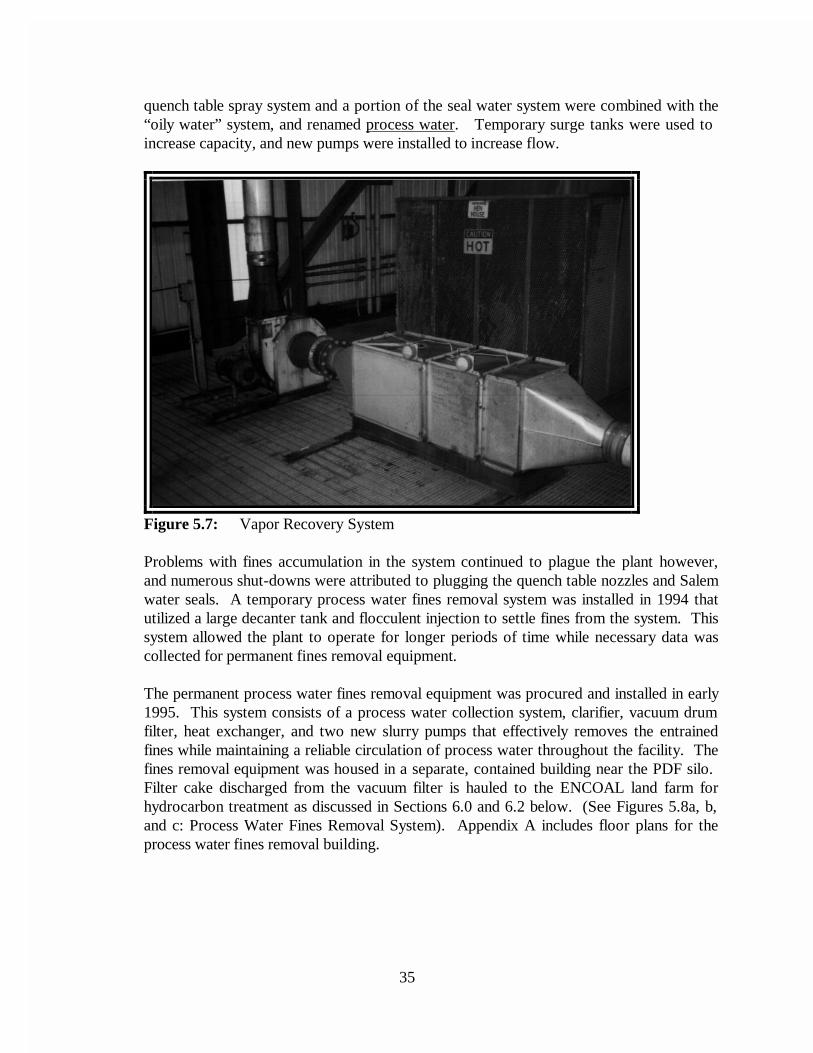
5.7 Vapor Recovery
Excessive odor from the plant process water circulation and sump system in early plantoperation lead to the design and installation of another new utility system called vaporrecovery. Extensive ambient air testing was done to ensure there were no harmful levelsof toxic materials in the ENCOAL plant. However, odors did hava a nauseating effect onsome people working in the plant for extended periods. Therefore the vapor recoverysystem was added. The system uses a small blower and an activated carbon filter tocollect and filter odorous air from the process water containment areas in the plant. Oncefiltered, the gases are exhausted to atmosphere outside the plant. This system has provento be very successful in reducing plant odors. (See Figure 5.7: Vapor Recovery System)
5.8 Process Water
The ENCOAL plant process water system was the most modified and changed utilityduring the 5 years of operation. The original design used a very small capacity pump andcirculation system called “oily water”. Its purpose was to gather and contain allwashdown and seal water that could include dissolved hydrocarbons, and used this waterto slurry fines from the pyrolyzer cyclone to be injected as rehydration water on PDF. While the system did work well to contain the water, the surge capacity and circulationsystem was found to be undersized and could not effectively handle the quantities ofslurried fines in the water. In addition to these problems, two other small utility systemscalled quench spray water and seal water were also found to be inadequate. The entire
35
quench table spray system and a portion of the seal water system were combined with the“oily water” system, and renamed process water. Temporary surge tanks were used to increase capacity, and new pumps were installed to increase flow.
Figure 5.7: Vapor Recovery System
Problems with fines accumulation in the system continued to plague the plant however,and numerous shut-downs were attributed to plugging the quench table nozzles and Salemwater seals. A temporary process water fines removal system was installed in 1994 thatutilized a large decanter tank and flocculent injection to settle fines from the system. Thissystem allowed the plant to operate for longer periods of time while necessary data wascollected for permanent fines removal equipment.
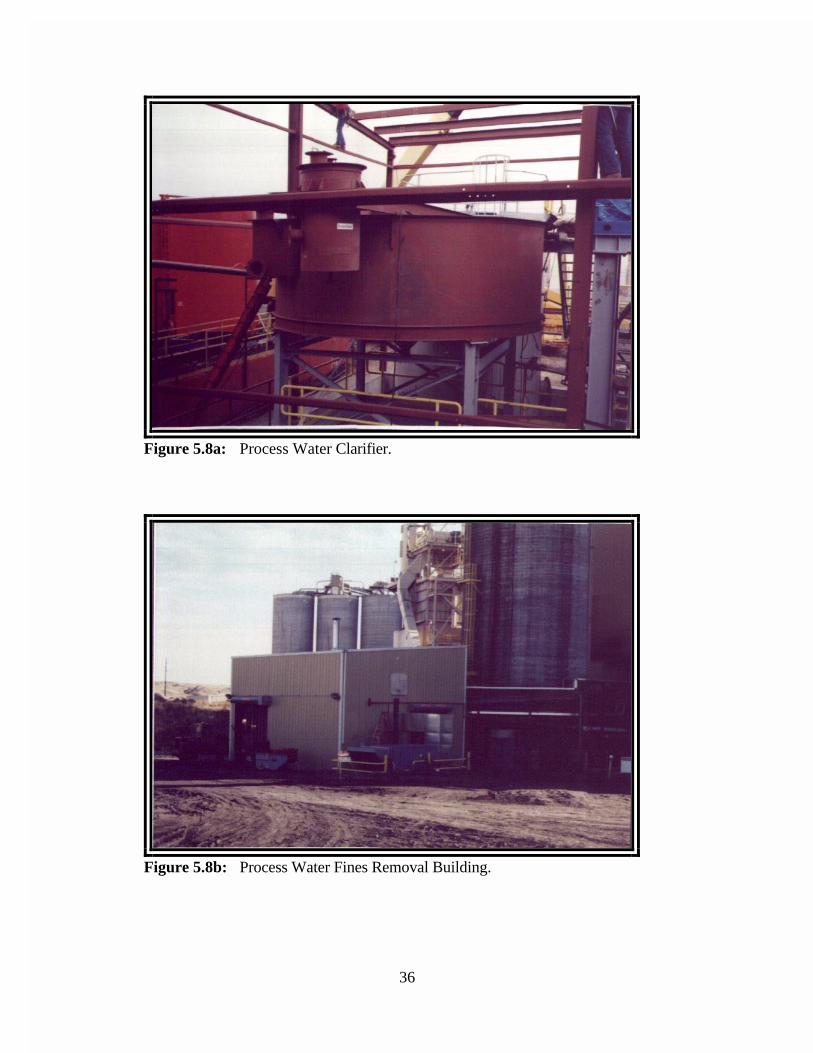
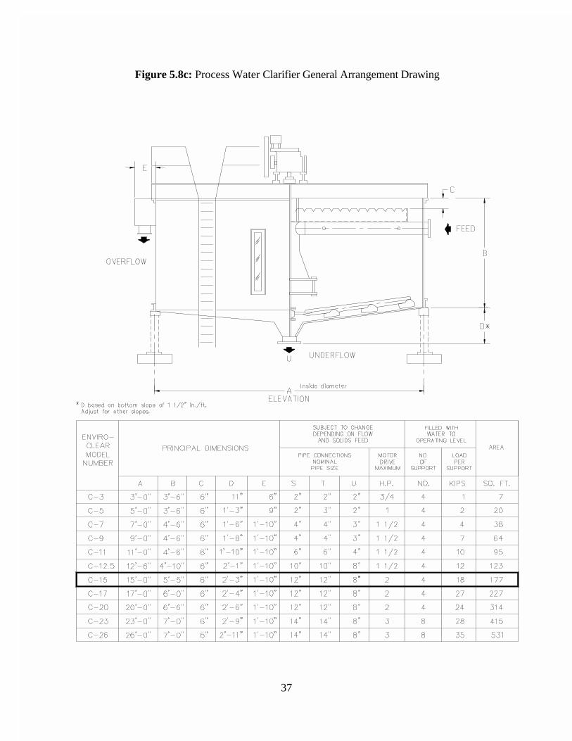
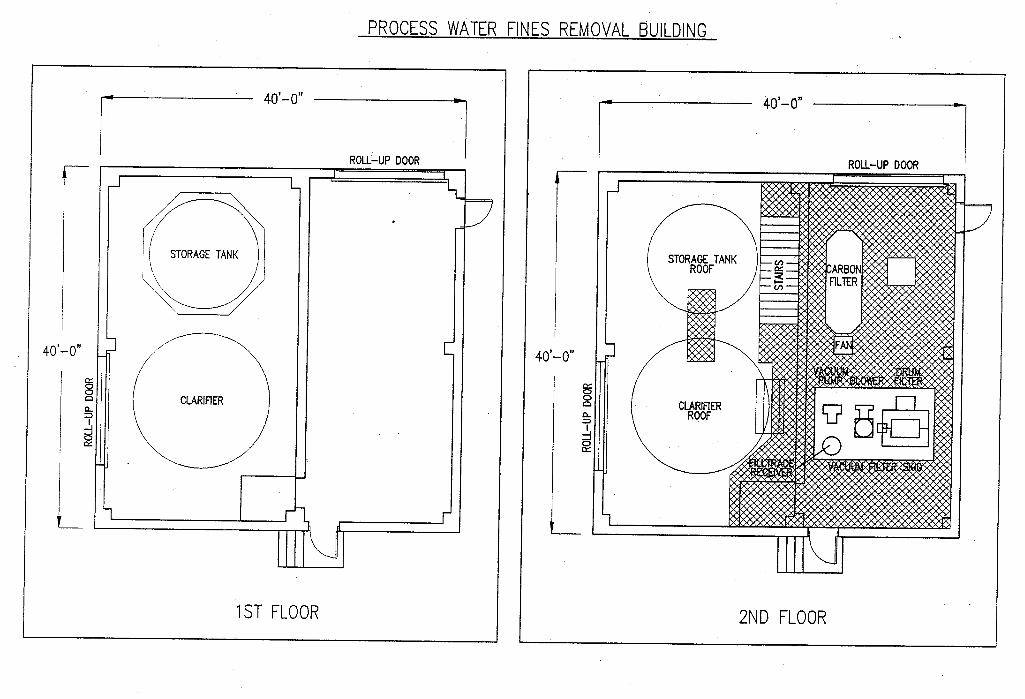
The permanent process water fines removal equipment was procured and installed in early1995. This system consists of a process water collection system, clarifier, vacuum drumfilter, heat exchanger, and two new slurry pumps that effectively removes the entrainedfines while maintaining a reliable circulation of process water throughout the facility. Thefines removal equipment was housed in a separate, contained building near the PDF silo. Filter cake discharged from the vacuum filter is hauled to the ENCOAL land farm forhydrocarbon treatment as discussed in Sections 6.0 and 6.2 below. (See Figures 5.8a, b,and c: Process Water Fines Removal System). Appendix A includes floor plans for theprocess water fines removal building.
36
Figure 5.8a: Process Water Clarifier.
Figure 5.8b: Process Water Fines Removal Building.
37
Figure 5.8c: Process Water Clarifier General Arrangement Drawing
38
6.0 ENVIRONMENTAL MODIFICATIONS
ENCOAL’s policy is to always operate in an environmentally responsible manner. The goal is tohave no citations or Notice Of Violations (NOV’s). The original plant was designed to have noeffluents other than normal coal washdown water and no solids waste streams. Emissions weredesigned to be less than 100 tons per year of SOx, NOx, methane, particulates or CO. Asexpected, the demonstration plant has provided a great learning experience in the control ofenvironmental releases.
The following list includes some of the more significant environmental modifications to theENCOAL facilities;
1) Solids collected in the process water stream as described above can not berecovered in the product stream via rehydration as originally conceived. They arevery expensive to recover in the quantities produced so a biological disposalmethod or landfarm was developed.
2) The requirement of atmospheric exposure for finishing PDF has led to the need forlonger term laydown and storage areas than envisioned for PDF pile testing in theoriginal plant concepts.
3) Production at less than design capacity resulted in modifications to the operatingpermits requested from the State of Wyoming.
4) Low production totals delayed the need for installation of the PermanentPrecipitate Storage Reservoir. This resulted in permit revisions and addition of anevaporation system to the temporary reservoir.
5) Odors in the processing plant proved to be very objectionable for many operators. Extensive ambient air monitoring work revealed no EPA listed toxins inconcentrations anywhere close to Federal limits. However, it was decided toinstall a vapor recovery system on all process water holding vessels as described inSection 5.7.
6.1 Air Quality Issues
Late in 1992, ENCOAL staff members met with the WDEQ to discuss the status of plantoperation, notification requirements and the status of stack gas monitoring. As a result ofthis meeting, a letter was sent to the WDEQ confirming the stack gas monitoring scheduleand explaining ENCOAL's temporary noncondensible gas venting arrangements installedfor the PDF quench table. The letter, which also discussed the quench table steamcondenser tests scheduled for January 1993, was approved in December 1992.
39
In mid-1993, ENCOAL submitted a permit application for the vapor collection systemexhaust on the process water system. Although a permit was not required by currentregulations, it was agreed that a permit would be prudent, and data were collected fromplant runs to support a permit application.
Stack Gas Emissions
In October 1995, a third-party testing firm mobilized to perform emission testingnecessary to obtain ENCOAL's permit to operate from the WDEQ. The stack andemissions testing using DEQ-approved protocol was successfully completed in November1995, and indicated that the plant is operating within permitted limits for NOx, sulfuroxides, carbon monoxide, volatile organic compounds, and particulates. The SO2
Continuous Emission Rate Monitoring System for the ENCOAL plant stack gas wascertified as a result of the testing.
Air Quality Permit
Revisions to the AQ permit, delayed since the beginning of Phase III by interruptions inplant operation, were reviewed by the WDEQ in March 1996, and ENCOAL responded tothe Department's questions. In mid-1996, ENCOAL received a notice of completeness forits application for Section 21 AQ permit from the WDEQ. The permit included a 5-acrelaydown area that was not anticipated in the original application. The applicationproceeded smoothly through the technical review and was formally approved in November1996.
6.2 Land Quality Issues
Permanent Precipitate Storage Reservoir
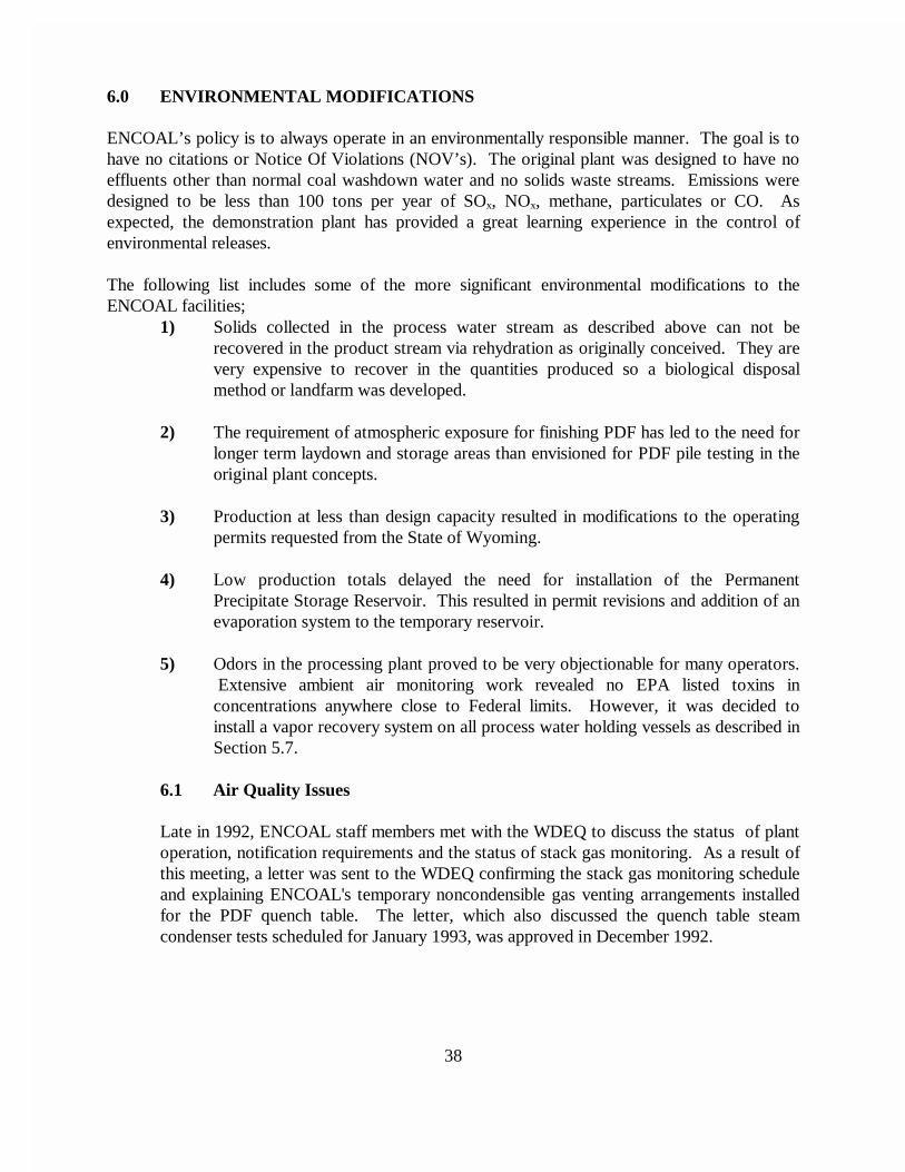
A permanent storage reservoir was part of ENCOAL's original plan, but because theWDEQ questioned the location of the permanent precipitate disposal pond, an alternativepermit application was submitted, modifying an existing mine sediment pond. Because thetemporary pond proved adequate far longer than originally believed, ENCOAL wasallowed to defer permitting and construction of the permanent disposal pond until 1995,when geotechnical survey holes were drilled on a secondary site for the permanentprecipitate storage reservoir. After core sample testing indicated that soils wereacceptable at the construction site, the design for the pond was completed in cooperationwith the WDEQ, and the permit application was finalized in June 1995. When the WDEQdetermined that public notice would be required, construction was deferred, this time until1996, and options to extend the life of the temporary pond were again evaluated. Afterweighing several options, a system designed to improve the evaporation rate was installed. The system included a portable diesel powered pump, floating platform and a nozzle bankto spray the effluent into the air. It was approved by the WDEQ and started up inSeptember 1996. (See Figure 6.1: Portable Evaporation System)
40
Figure 6.1: Portable Evaporation System.
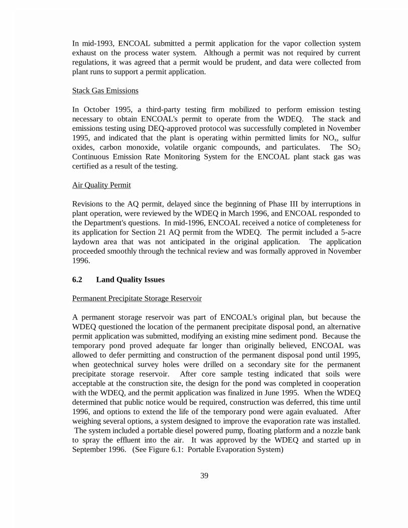
The WDEQ reviewed the application for revisions to the permanent pond, and ENCOALresponded to WDEQ questions in March 1996. At that time, a bid package forconstruction of the permanent reservoir was sent to potential contractors. The permit forconstruction cleared public comment and was sent to WDEQ's head office; final approvalfor the reservoir was received in June. Reservoir construction began the first week in Julyand continued through 1996. This reservoir is scheduled to be commissioned for use inJuly 1997. (See Figure 6.2: Permanent Precipitate Storage Reservoir)
Land Farm
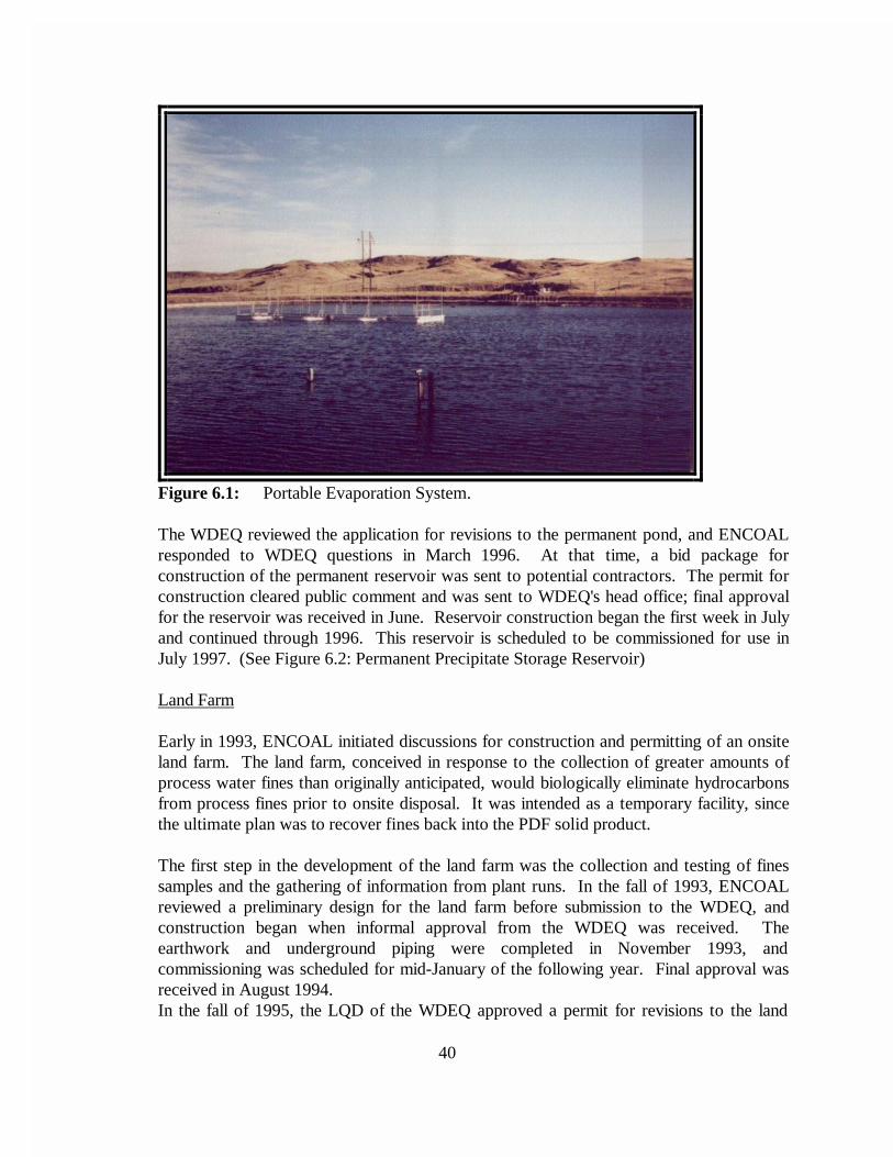
Early in 1993, ENCOAL initiated discussions for construction and permitting of an onsiteland farm. The land farm, conceived in response to the collection of greater amounts ofprocess water fines than originally anticipated, would biologically eliminate hydrocarbonsfrom process fines prior to onsite disposal. It was intended as a temporary facility, sincethe ultimate plan was to recover fines back into the PDF solid product.
The first step in the development of the land farm was the collection and testing of finessamples and the gathering of information from plant runs. In the fall of 1993, ENCOALreviewed a preliminary design for the land farm before submission to the WDEQ, andconstruction began when informal approval from the WDEQ was received. Theearthwork and underground piping were completed in November 1993, andcommissioning was scheduled for mid-January of the following year. Final approval wasreceived in August 1994. In the fall of 1995, the LQD of the WDEQ approved a permit for revisions to the land
41
farm that included a new concrete holding area for wet fines, a higher retaining dike toincrease capacity, and provisions for continuous operation with pit disposal of treatedfines. Specifications to complete the modifications were developed, and a bid packagewas issued. Modifications began in July 1996 and were completed 2 months later, and thefacility was commissioned in October of the same year. (See Figure 6.3: ENCOAL LandFarm)
One of ENCOAL’s most important accomplishments during the life of the project is its safetyrecord. Since October 1990, only nine reportable accidents and four lost time accidents werereported for all personnel, including contractors and associated workers. This lost time accidentrate is less than one-third the most recent available rate for petroleum and coal processingindustries, while the number of reportables is less than one-fifth.
ENCOAL achieved this by consistently supporting a policy that encouraged operator andcontractor involvement in plant operations to ensure proper safety awareness. Modifications thatreduced or removed the potential for injury were continually made to the facility as a result of thispolicy. Some of these modifications included installation of platforms, handrails, stairways,guards, blinds, and man-ways all oriented to ease maintenance of the plant while providing safeaccess to the equipment. Other modifications made to the facility for administration purposes arediscussed below.
1) A 40 foot by 80 foot maintenance shop and warehouse was constructed in 1992. This facility is used for a welding shop, tool storage, and commonly used partswarehouse. (See Figure 7.0a: ENCOAL Maintenance Shop)
2) A 25 foot by 45 foot addition to the original control room building wasconstructed in 1995. The expansion was necessary to provide storage space, alarger training/lunchroom, a maintenance office/library, and additional offices. (See Figures 7.0b and c: ENCOAL Control Room Building Expansion)
8.0 CONCLUSIONS
The goals of the ENCOAL Project have not only been met, but exceeded. Sixteen unit trains ofPDF have been shipped and successfully burned at seven utilities. PDF has also been tested as areductant (combined with iron ore) in the DRI process, and holds promise as a blast furnaceinjectant. The LFC process has been demonstrated and improved through the modificationsdiscussed in this report. (Table A.1 in Appendix A summarizes the changes and additions to theENCOAL plant equipment list over the 5 year period). Almost 5 years of operating data havebeen collected as a basis for the evaluation and design of a commercial plant. Finally, thelicensing effort has reached the international level: agreements have been signed, and manyopportunities are being developed.
Although major DOE objectives have been reached, some issues need to be resolved before acommercial plant project can proceed. The ENCOAL Demonstration Plant must continue to testthe viability of alternate commercial-scale equipment, deliver additional test burn quantities ofproducts, train operators for the commercial plant and provide additional design and economicdata for the commercial plant. ENCOAL also needs to install an in-plant finisher that willsubstantiate the large-scale testing of PDF finishing, the final stage of stabilization.
Efforts to license the technology will proceed under the auspices of TEK-KOL, both domesticallyand internationally. These activities are in progress as further described in other reports.[1,3]
43
Figure 7.0a: ENCOAL Maintenance Shop.
Figure 7.0b: ENCOAL Control Building.
44
12'-4 1/4"9'9'
NEW BASE/WALL CABINETS
APR
OX.
10'
8'-0"
5'-5
"
4'-0
"
MACHINEVENDING
STO
RAG
E SH
ELVE
S O
R L
OC
KER
S
AREAS T O R A G E
UTILITYAND
SAFETY,LOCKER,
PROJECTOR SCREENSUSPENDED OVERHEAD
SAFETY CABINETSWARDROBE TYPELOCKERS OR
LOCKERSRESPITORYEXISTINGRELOCATED
O U T L E TOUTSIDE WALLRELOCATED
WALL OUTLET NEW EXTERNAL
N E WOFFICE
(MAINT/LIBRARY)
N E WOFFICE
(ENGINEERING)(SAFETY)OFFICE
N E W
MANAGER)
(OPERATIONS
MANAGER)
(RESOURCE
5. ALL DOORS ARE 3'-0" WIDE BY 7'-0" TALL.
FRAME OPENING, NO DOORTO NEW MECHANICAL ROOM,OF OLD WALL FOR ACCESSREMOVED 3 ' -6" WIDE SECTION
4'
4'-8"
5'-8"
45'-0".4. BUILDING EXPANSION MEASURES 25'-0" x
OR FOR FINAL FRAMING. DIMENSIONS MAY BE ADJUSTED BY CONTRACT- "OUTSIDE-OF-WALL" DIMENSIONS. INTERIOR OF THE BUILDING EXTERIOR WALLS WHICH ARE CENTERLINE DIMENSIONS WITH THE EXCEPTION3. DIMENSIONS ARE GENERALLY CENTERLINE
DESIGN FOR EXPANSION. WALLS ARE 4 5/8" THICK. DUPLICATE THIS2. EXTERIOR WALLS ARE 10" THICK INTERIOR
EXPANSION FACILITIES. SUPPORTS. DUPLICATE THIS DESIGN FOR WALLS WITH 15' DEEP CAISSONS FOR PILLAR1. EXISTING FOUNDATION INCLUDES 4' FROST
NOTES:
HOLDING TANKAND
SEPTIC TANKF O R
AREARELOCATION
AREA
NEW HVACEQUIPMENT
EQUIPMENTHVAC
RELOCATED
14'-4"
75'-0"6'-0" 15'-2" 9'-4" 9'-4" 16'-2"
45'-0"
14'-4"
7'-0"
23'-8"
WINDOWRELOCATED
R O O M
LUNCH/MEETING
N E W
AREA
KITCHENN E W
NEW FLOOR DRAIN
NEW FLOOR DRAIN
MECHANICALN E W
R O O M
S T O R A G EC L O S E T
OLD
WAL
L LI
NE
NATURAL GAS LINEU N D E R G R O U N DIN NEW LUNCH ROOM
WINDOW, RELOCATED WINDOWREMOVED EXISTING WALL AND
NEW WINDOWNEW WINDOW
C O N T R O LEXISTING
R O O M
EXISTING WINDOW
ELECTRICALEXISTING
R O O MEXISTING FLOOR DRAIN
EXISTING FLOOR DRAIN
R O O M
EXISTINGMECHANICAL EXISTING
OFFICE
EXISTING
OFFICE LAB
EXISTING
Figure 7.0c: ENCOAL Control Room Building Expansion Floor Plan
45
REFERENCES
1. "ENCOAL Mild Coal Gasification Project: ENCOAL Project Final Report," U.S.Department of Energy Report, July 1997.
2. “ENCOAL Mild Coal Gasification Public Design and Construction Report,” U.S.Department of Energy Report, December 1994.
3. “ENCOAL Mild Coal Gasification Project: Commercial Plant Feasibility Study,” U.S.Department of Energy Report, July 1997.
Dryer On-Gas CorubustorRecycle Gas Blo\\w@rely/-er On-Gas CombustorForced Draft Air Blower to 302BForced Draft Air Blower to 30 1 BPDF Air Cooler Fan W/MotorVFB Finishing Blo\+crVoith Coupling for 3055VFB Booster Blo\vcrVFB Cooling BlonrerOily Fines Vapor FanOily Fines Vapor FilterME; Application HeaterMK Appl Pump W/Var. Frcq. Mtr., Dr. JacketHorizontal ScrubberScrubber Surge TankScrubber Circulation Pump W/Mcch. Seal
W.M. MeyerSalem Furnace Compan!W.M. McycrWolf & Assoc., Falk. WoodsBrewer SteelCarrierDucon Environment al Sys.Thcrml TransferW.M. MeyerW.M. MeyerWolf & Assoc., Falk. WoodsRx0 InternationalRotolok, Inc.Superior Hard SurfacingSuperior Hard SurfacingEaton MetalsUnion P u m p Conipan~Union Prirrip Conkp;u~~Lodge-CottrcllLodge-Cot trcllLodge-CottrcllRoperJ. W. Williams, Inc.Goulds Pu~ups, Inc.
Glycol-Water Circulating PumpSpare for 20075Boiler Chemical JlijcctionInjection Pump for 2007LProcess Water Booster PumpProcess Water Booster PumpsAmmonia Chemical Injection SystmAmmonia Injection Pur~p
Offspcc Oil FilterOffspcc Oil FilterMK Car Topper TankMK Car Topper PurIrpMK Car Topper Pump StrainersOfispcc Chemical Injection PumpEuwgcncy Glycol Tracing PumpNitrogen Vaporizer Glycol PunlpOily Fines Circulation TankOily Fiucs Circulation PumpFiltrating ReccivcrFilter Tub AgitatorVacuum Drum FilterClarifier Denration TaukClarifier Underflow PunIpClarifier RakeClarifierWater TrapVacu11111 PumpFlocculant Blcndiug UnitOily Water Surge TankFiltrate PumpDischarge BlowerOily Water Bulk TankOily Water Return PumpCoagIllallt PlllllpCoal Storage SiloPDF BinFire Water Booster Pu11lp
H?udraulic Ponw Supply for 2 123VMotor for Hydraulic Ponw SuppI!Coal ScreenMotor for Coal ScreenScrccnirg Plant SuiilpSlurry InjectionManifold W/Hydra-C> clor~cs (&XI)
Union Pump CoInpa tgUnion Pump CornpanqYork ShipleyYork ShipleyGouldsGouldsYork ShipleyYork Shiplc)The Eads Cornpan>The Eads CompanyJ. W. WilliamsRoperRoscdaleThe Eads Con~panj
BlackrncrQuadm. Kenflo\kWilson1 WeldingGeorgia Iron WorksWestccllWestcchWestcchEuviroclcarRoperErrviroclcarErwroclcarwcstccllWcstccl1Great-FLOCKissack Water Ct; Hot Oil Svc.WcstechWestccliKissack Water CI: Hot Oil Svc.RoperGreat-FLOC1 IorrlIlall
PDF Truck Loading CottvcyorCoal Analyzer Be1 t ConveyorCoal Fines Truck Loading ConveyorFines Truck Loading Tclcscopic Spor~tFines Bin Cutoff Gate for 2 1 16VFines Bin Cutoff Gate for 2 1 16VCutoff Gate for 5OAV - Vendor PackageCutoff Gale for 2 10 1 AFeed Coal Silo IIcatcrPDF Bin Heater
DELETED
ADDED
ADDEDDELETED
ADDEDADDEDADDEDADDED
Dyer Fines ConveyorDust Collection BaghouseRaw Coal S-Bell Cleanup Screw ConveyorCooling Waler htakc Sh-ucturcCooling Water PumpSpare for 220 1 JCooling Water Filter W/MotorCooling Water Filter W/MotorCooling Water Clictnical Injccliott Puti~p
SCR Platlt Fines Sump PutnpPDF Plant Containtnctit Pump