4.4 Hip Disarticulation and Hemip-elvectomy 094.5 Below-KneeAmputations 09
5. The Postsurgical Period 096. Prostheses for Various Types of Amputation 10
6.1 Prostheses for Syme's Amputation 116.2 Prostheses for Below-Knee Amputations 116.3 Prostheses for the Knee-Disarticulation and Other Knee-Bearing Cases 126.4 Prostheses for Above-Knee Cases 136.5 Prostheses for Hip-Disarticulation and Hemi-pelvectomy Cases 15
11. Specific Gait Training 2711.1Sound-leg step forward (two-hand support) 2711.2 Sound-leg step backward (two-hand support) 2811.3 Sound-leg step through (two-hand support) 2811.4 Sound-leg step through (one-hand support) 2911.5 Sound-leg step through (without support) 2911.6 Prosthetic-leg step forward (two-hand support) 3011.7 Prosthetic-leg step backward (two-hand support) 30
11.8 Prosthetic-leg step through (two-hand support) 3111.9 Prosthetic-leg step forward (one-hand support) 3111.10 Prosthetic-leg step through (without support) 3211.12 Walking between the parallel bars (without support) 33
1. INTRODUCTION OF PROSTHESIS
Artificial legs, or prostheses, are intended to restore a degree of normal function to amputees. Mechanical devices that allow amputees to walk again have probably been in use since ancient times, the most notable one being the simple peg leg. Surgical procedure for amputation, however, was not largely successful until around 600 B.C. Armorers of the Middle Ages created the first sophisticated prostheses, using strong, heavy, inflexible iron to make limbs that the amputee could scarcely control. Even with the articulated joints invented by Ambroise Paré in the 1500s, the amputee could not flex at will. In the 19th century, the American Civil War raised interest and led to advanced technology because of the high amount of amputations. The twentieth century has seen the greatest advances in prosthetic limbs. The first major improvement of the 20th century came in 1912, when an aluminum prosthetic leg was created by Marcel and Charles Desoutter after Marcel lost a leg in an aviation accident. Materials such as modern plastics have yielded prosthetic devices that are strong and more lightweight than earlier limbs made of iron and wood. New plastics, better pigments, and more sophisticated procedures are responsible for creating fairly realistic-looking skin.When a person becomes a limb amputee, he or she is faced with staggering emotional and financial lifestyle changes. The amputee requires a prosthetic device(s) and services which become a life-long event. Prosthesis is an artificial extension that replaces a missing body part such as an upper or lower body extremity. It is part of the field of bio- mechatronics, the science of fusing mechanical devices with human muscle, skeleton, and nervous systems to assist or enhance motor control lost by trauma, disease, or defect. An artificial limb is a type of prosthesis that replaces a missing extremity, such as arms or legs. The type of artificial limb used is determined largely by the extent of an amputation or loss and location of the missing extremity. Artificial limbs may be needed for a variety of reasons, including disease, accidents, and congenital defects. There are four main types of artificial limbs:-These include the transtibial, transfemoral, transradial, and transhumeral prostheses.
2. TYPES OF PROSTHESIS
2.1 Transradial Prosthesis Transradial prosthesis is an artificial limb that replaces an arm missing below the elbow. Two main types of prosthetics are available. Cable operated limbs work by attaching a harness and cable around the opposite shoulder of the damaged arm. The other form of prosthetics available is myoelectric arms. These work by sensing, via electrodes, when the muscles in the upper arm moves, causing an artificial hand to open or close.
Fig.(1) Transradial pprosthesis
2.2 Transhumeral Prosthesis Transhumeral prosthesis is an artificial limb that replaces an arm missing above the elbow. Transhumeral amputees experience some of the same problems as transfemoral amputees, due to the similar complexities associated with the movement of the elbow. This makes mimicking the correct motion with an artificial limb very difficult.
Fig.(2) Transhumeral Prosthesis
2.3 Transfemoral Prosthesis Transfemoral prosthesis is an artificial limb that replaces a leg missing above the knee. Transfemoral amputees can have a very difficult time regaining normal movement. In general, a transfemoral amputee must use approximately 80% more energy to walk than a person with two
whole legs. This is due to the complexities in movement associated with the knee. In newer and more improved designs, after employing hydraulics, carbon fiber, mechanical linkages, motors, computer microprocessors, and innovative combinations of these technologies to give more control to the user. The type of prosthesis depends on what part of the limb is missing. Major technological advancements drive the limb prosthetics market. Outstanding innovative advancements in technology have catalyzed the modernization of prosthetics, spurring a significant growth in the prosthetics market. Thanks to these developments, today’s prosthetic devices cater to the specific needs of patients. Products ranging from conventional knees to energy-storing feet help amputees lead more normal and productive lives. The prosthetics market is impacted by the occurrence of disease, war, and accidents. Diabetes and peripheral vascular diseases rank as the number one cause of amputation in the United States, where an average 185,000 amputations are performed annually, thus increasing the consumer base and presenting opportunities for service providers. While diseases such as diabetes and peripheral vascular disease are the leading causes of amputation, accidents and war continue to play a major role in driving the limb prosthetics market. The demand for restoring mobility and independence from amputees including a growing number of amputee soldiers impacts the market positively, urges manufacturers to address amputee issues and the market. The impact of technology on this market is tremendous and it is likely to continue for the next several years in response to novel innovations such as bionic technology, sensor technology, artificial intelligence, and micro mechatronics. The growing consumer base of amputees drives the market with demands for improvement in quality of life and innovation will address quality of life needs. Technological growth and an increasing consumer base of amputees are bolstering the prosthetics market growth, according to an analysis from the business and research consulting firm Frost & Sullivan.
Fig.(3) Transfemoral Prosthesis
2.4 Transtibial Prosthesis Transtibial prosthesis is an artificial limb that replaces a leg missing below the knee. Transtibial amputees are usually able to regain normal movement more readily than for someone with a transfemoral amputation, due in large part to retaining the knee, which allows for easier movement
Fig.(4) Transtibial Prosthesis
2.5 Neuroprosthetics
Current prosthetic limbs are far less than optimal. All prosthetics must deal with the issues of function, control and fit. In other words – How does the current prosthesis function? Can the prostheses be controlled? How does it fit? Each of these issues present 14 and concerned with developing artificial prosthetic devices to replace or improve the function of an impaired nervous system. Neural prostheses are a series of devices that can substitute a motor, sensory or cognitive modality that might have been damaged as a result of an injury or a disease. The goal of the neuroprosthetic limb is to restore an optimal degree of natural function for the missing or damaged limb .
Fig.(5) Neuroprosthetics
3. AMPUTATION
Amputations are caused by accidents, disease, and congenital disorders. Approximately 74% are due to peripheral vascular disease (poor circulation of the blood) and cancer; 23% are due to accidents, and 3% are due to a problem found at birth. The accidents most likely to result in amputation are traffic accidents, followed by farm and industrial accidents. Amputations in the case of disease are performed as a lifesaving measure. The diseases that cause the most amputations are peripheral vascular disease (poor circulation of the blood) and cancer. A congenital disorder or defect of a limb present at birth is not an amputation, but rather a lack of development of part or all of a limb. A person born with a limb deficiency usually can be helped by use of an artificial limb. Sometimes amputation of part of a deformed limb or other surgery may be desirable before the application of an artificial limb. Above-knee (trans-femoral) amputees form the second largest group of amputees. Surgeons preserve as much length in thigh amputations as is medically feasible because longer stumps provide better control over the prosthesis. Experienced surgeons avoid leaving unnecessary skin and muscle. Disarticulation at the knee preserves the entire thigh, and, in addition, permits "end-bearing", or the ability of the stump to carry a substantial portion of the body weight over the end. Amputations are generally classified according to the level at which they are performed. Some amputation levels are referred to by the name of the surgeon credited with developing the amputation technique used.
4. LOWER-EXTREMITY AMPUTATIONS
4.1 Syme's Amputation Developed about 1842 by James Syme, a leading Scottish surgeon, the Syme amputation leaves the long bones of the shank (the tibia and fibula) virtually intact, only a small portion at the very end being removed. The tissues of the heel, which are ideally suited to withstand high pressures, are preserved, and this, in combination with the long bones, usually permits the patient to bear the full weight of his body on the end of the stump. Because the amputation stump is nearly as long as the unaffected limb, a person with Syme's amputation can usually get about the house without prosthesis even though normal foot and ankle action has been lost. Atrophy of the severed muscles that were formerly attached to bones in the foot to provide ankle action results in a stump with a bulbous end which, though not of the most pleasing appearance, is quite an advantage in holding the prosthesis in place. Since its introduction, Syme's operation has been looked upon with both favor and disfavor among surgeons. It seems to be the consensus now that "the Syme" should be performed in preference to amputation at a higher level if possible. In the case of most women, though, "the Syme" is undesirable because of the difficulty of providing a prosthesis that matches the shape of the other leg.
Fig.(6) Syme's Amputation (The tissues of the heel, which are ideally suited to withstand high pressures)4.2 Knee-Bearing Amputations Complete removal of the lower leg, or shank, is known as a knee disarticulation. When the operation is performed properly, the result is an efficient, though bulbous, stump capable of carrying the weight-bearing forces through the end. Unfortunately, the length causes some problems in providing an efficient prosthesis because the space used normally to house the mechanism needed to control the artificial shank properly is occupied by the end of the stump. Nevertheless, prostheses have been highly beneficial in knee-disarticulation cases. Development of adequate devices for obtaining control of the shank is currently under way, and such devices should be generally available in the near future. Several amputation techniques have been devised in an attempt to overcome the problems posed by the length and shape of the true knee-disarticulation stump. The Gritti-Stokes procedure entails placing the kneecap, or patella, directly over the end of the femur after it has been cut off about two inches above the end. When the operation is performed properly, excellent results are obtained, but extreme skill and expert postsurgical care are required. Variations of the Gritti-Stokes amputation have been introduced from time to time but have never been used widely.
4.3 Above-Knee Amputations Amputations through the thigh are among the most common. Total body weight cannot be taken through the end of the stump but can be accommodated through the ischium, that part of the pelvis upon which a person normally sits.
Fig.(7) Above-Knee Amputations
4.4 Hip Disarticulation and Hemipelvectomy A true hip disarticulation involves removal of the entire femur, but whenever feasible the surgeon leaves as much of the upper portion of the femur as possible in order to provide additional stabilization between the prosthesis and the wearer, even though no additional function can be expected over the true hip disarticulation. Both types of stump are provided with the same type of prosthesis. With slight modification the same type of prosthesis can be used by the hemipelvectomy patient, that is, when half of the pelvis has been removed. It is surprising how well hip-disarticulation and hemipelvectomy patients have been able to function when fitted with the newer type of prosthesis
4.5 Below-KneeAmputations
Any amputation above the Syme level and below the knee joint is known as a below-knee amputation. Because circulatory troubles have often developed in long below-knee stumps, and because the muscles that activate the shank are attached at a level close to the knee joint, the below-knee amputation is usually performed at the junction of the 22 upper and middle third sections. Thus nearly full use of the knee is retained- an important factor in obtaining a gait of nearly normal appearance. However, it is rare for a below-knee amputee to bear a significant
amount of weight on the end of the stump; thus the design of prostheses must provide for weight-bearing through other areas. Several types of surgical procedures have been employed to obtain weight-bearing through the end of the below-knee stump, but none has found widespread use.
5. THE POSTSURGICAL PERIOD The period between the time of surgery and time of fitting the prosthesis is an important one if a good functional stump, and thus the most efficient use of a prosthesis, is to be obtained. The surgeon and others on his hospital staff will do everything possible to ensure the best results, but ideal results require the wholehearted cooperation of the patient. It is not unnatural for the patient to feel extremely depressed during the first few days after surgery, but after he becomes aware of the possibilities of recovery, the outlook becomes brighter, and he generally enters cooperatively into the rehabilitation phase. As soon as the stump has healed sufficiently, exercise of the stump is started in order to keep the muscles healthy and reduce the possibility of muscle contractures. Contractures can be prevented easily, but it is most difficult and sometimes impossible to correct them. At first exercises are administered by a therapist or nurse; later the patient is instructed concerning the type and amount of exercise that should be undertaken. The patient is also instructed in methods and amount of massage that should be given the stump to aid in the reduction of the stump size. Further, to aid shrinkage, cotton-elastic bandages are wrapped around the stump and worn continuously until prosthesis is fitted. The bandage is removed and reapplied at regular intervals- four times during the day, and at bedtime. It is most important that a clean bandage is available for use each day. The amputee is taught to apply the bandage unless it is physically impossible for him to do so, in which case some member of his family must be taught the proper method for use at home. To reduce the possibility of contractures, the lower-extremity stump must not be propped upon pillows. Wheel chairs should be used as little as possible; crutch walking is preferred, but the above-knee stump must not be allowed to rest on the crutch handle
6. PROSTHESES FOR VARIOUS TYPES OF AMPUTATION Much time and attention have been devoted to the development of mechanical components, such as knee and ankle units, for artificial limbs, yet by far the most important factors affecting the successful use of a prosthesis are the fit of the socket to the stump and the alignment of the various parts of the limb in relation to the stump and other parts of the body. Thus, though many parts of a prosthesis may be mass-produced, it is necessary for each limb to be assembled in correct alignment and fitted to the stump to meet the individual requirements of the intended user. To make and fit artificial limbs properly requires a complete understanding of anatomical and physiological principles and of mechanics; craftsmanship and artistic ability are also required. In general, an artificial limb should be as light as possible and still withstand the loads imposed upon it. In the United States willow and woods of similar characteristics have formed the basis of construction for more limbs than any other material, though aluminum, leather-and-steel combinations, and fibre have been used widely. Wood construction is still the type most used in the United States for above-knee prostheses, but plastic laminates similar to those so popular in small-boat construction are the materials of choice for virtually all other types of prostheses. Plastic laminates are light in weight, easy to keep clean, and do not absorb perspiration. They
may be molded easily and rapidly over contours such as those found on a plaster model of a stump. Plastic laminates can be made extremely rigid or with any degree of flexibility required in artificial-limb construction. In some instances, especially in upper-extremity sockets, the fact that most plastic laminates do not permit water vapor to pass to the atmosphere has caused discomfort, but recently a porous type has been developed by the Army Medical Biomechanical Research Laboratory (formerly the Army Prosthetics Research Laboratory).Except experimentally, its use thus far has been restricted to artificial arms. Of course, most of the mechanical parts are made of steel or aluminum, depending upon their function. The cast, or wrap, is removed from the stump and filled with a plaster-of-Paris solution to form an exact model of the stump which-after being modified to provide relief for any tender spots, to ensure that weight will be taken in the proper places, and to take full advantage of the remaining musculature- can be used for molding a plastic-laminate socket. Often a "check" socket of cloth impregnated with beeswax is made over the model and tried on the stump to determine the correctness of the modifications. For upper-extremity cases the socket is attached to the rest of the prosthesis and a harness is fabricated and installed for operation of the various parts of the artificial arm. For the lower-extremity case the socket is fastened temporarily to an adjustable, or temporary, leg for walking trials. With this device, the prosthetist can easily adjust the alignment until both he and the amputee are satisfied that the optimum arrangement has been reached. Prosthesis can now be made incorporating the same alignment achieved with the adjustable leg. There are many kinds of artificial limbs available for each type of amputation, and much has been written concerning the necessity for prescribing limbs to meet the needs of each individual. This of course is true particularly in the case of persons in special or arduous occupations, or with certain medical problems, but actually limbs for a given type of amputation vary to only a small degree. Following are descriptions of the artificial limbs most commonly used in the United States today.
6.1 Prostheses for Syme's Amputation Perhaps the major reason Syme's amputation was held in such disfavor in some quarters was the difficulty in providing a comfortable, sufficiently strong prosthesis with a neat appearance. The short distance between the end of the stump and the floor made it extremely difficult to provide for ankle motion needed. Most Syme prostheses were of leather reinforced with steel side bars resulting in an ungainly appearance. Research workers at the Prosthetic Services Centre at the Department of Veterans Affairs of Canada were quick to realize that the use of the proper plastic laminate might solve many of the problems long associated with the Syme's prosthesis. After a good deal of experimentation, the Canadians developed a model in 1955 which, with a few variations, is used almost universally in both Canada and the United States today. Necessary ankle action is provided by making the heel of the foot of sponge rubber. The socket is made entirely of a plastic laminate. A full-length cutout in the rear permits entry of the bulbous stump. When the cutout is replaced and held in place by straps, the bulbous stump holds the prosthesis in place. In the American version, a window-type cutout is used on the side because calculations show that smaller stress concentrations are present with such an arrangementIn those cases where, for poor surgery or other reasons, full body weight cannot be tolerated on the end of the stump, provisions can be made to transfer all or part of the load to the area just below the kneecap. When this procedure is necessary, it can be accomplished more easily by use of the window-type cutout.
Fig.(8) Syme's Amputation (The tissues of the heel, which are ideally suited to withstand high pressures)6.2 Prostheses for Below-Knee Amputations Until recently most below-knee amputees were fitted with wooden prostheses carved out by hand. A good portion of the body weight was carried on a leather thigh corset, or lacer, attached to the shank and socket by means of steel hinges. The shape of corset and upper hinges also held the prosthesis to the stump. The distal, or lower, end of the socket was invariably left open. Other versions of this prosthesis used aluminum, fiber or molded leather, as the materials for construction of the shank and socket, but the basic principle was the same. Many thousands of below-knee amputees have gotten along well with this type of prosthesis, but there are many disadvantages. Because the human knee joint is not a simple, single-axis hinge joint, relative motion is bound to occur between the prosthesis and the stump and thigh during knee motion when single-jointed side hinges are used, resulting in some chafing and irritation. To date it has not been possible to devise a hinge to overcome this difficulty. Edema, or accumulation of body fluids, was often present at the lower end of the stump. Most of these prostheses were exceedingly heavy, especially those made of wood. In an attempt to overcome these difficulties, the Biomechanics Laboratory of the University of California, in 1958, designed what is known as the patellar-tendon-bearing (PTB) below-knee prosthesis. In the PTB prosthesis no lacer and side hinges are used, all of the weight being taken through the stump by making the socket high enough to cover the entire tendon below the patella, or kneecap. The patellar tendon is an unusually inelastic tissue which is not unduly affected by pressure. The sides of the socket are also made much higher than has usually been the practice in the past in order to give stability against side loads. The socket is made of molded plastic laminate that provides an intimate fit over the entire area of the socket, and is lined with a thin layer of sponge rubber and leather. Because it is rare for a below-knee stump to bear much pressure on its lower end, care is taken to see that only a very slight amount is present in that area. This feature has been a big factor int he shank recommended is of plastic laminate and the foot prescribed is usually the SACH (solid-ankle, cushion-heel) design but other types can be used. Eliminating the edema problem in many instances. The PTB prosthesis is generally suspended by means of a simple cuff, or strap, around the thigh just above the kneecap, but sometimes a strap from the prosthesis to a belt around the waist is used.
After the socket has been made, it is installed on a special adjustable leg so that the prosthetist can try various alignment combinations with ease. When both prosthetist and patient are satisfied, the leg is completed utilizing the alignment determined with the adjustable unit.It is now general practice in many areas to prescribe the PTB prosthesis in most new cases and in many old ones, and if side hinges and a corset are indicated later, these can be added. Stumps as short as 2-1/2 in. have been fitted successfully with the PTB prosthesis. In special cases, such as extreme flexion contracture, the so-called kneeling-knee, or bent-knee, prosthesis may be indicated. The prosthesis used is similar to that used for the knee-disarticulation case.
Fig.(9) Prostheses for Below-Knee
6.3 Prostheses for the Knee-Disarticulation and Other Knee-Bearing Cases Because of the bulbous shape of the true knee-disarticulation stump, it is not possible to use a wooden socket of the type used on the tapered above-knee stump. To allow entry of the bulbous end, a socket is molded of leather to conform to the stump and is provided with a lengthwise anterior cutout that can be laced to hold the socket in position. Because of the length of the knee-disarticulation and supracondylar stump, it is not possible to install any of the present knee units designed for above-knee prostheses and, therefore, heavy-duty below-knee joints are generally used. Most prosthetists try to provide some control of the shank during the swing phase of walking by inserting nylon washers between the mating surfaces of the joint to provide friction and by using check straps. Better devices for control of the knee joint are being developed and should be available in the near future.
6.4 Prostheses for Above-Knee Cases
The articulated above-knee leg is in effect a compound pendulum actuated by the thigh stump. If the knee joint is perfectly free to rotate when force is applied, the effects of inertia and gravity tend to make the shank rotate too far backward and slam into extension as it rotates forward, except at a very slow rate of walking. The method most used today to permit an increase in walking speed is the introduction of some restraint in the form of mechanical friction about the knee joint. The limitation imposed by constant mechanical friction is that for each setting there is only one speed that produces a natural-appearing gait. When restraint is provided in the form of hydraulic resistance, a much wider range of cadence can be obtained without introducing into the gait pattern awkward and unnatural motions. Throughout the past century much time and effort have been spent in providing an automatic brake or lock at the knee in order to provide stability during the stance phase and to reduce the possibility of stumbling. Stability during the stance phase can be obtained by aligning the leg so that the axis of the knee is behind the hip and ankle axes. For most above-knee amputees in good health, such an arrangement has been quite satisfactory, but an automatic knee brake is indicated for the weaker or infirm patients.The prosthesis prescribed most commonly today for the above-knee amputee consists of a carved wooden socket, a single-axis knee unit with constant but adjustable friction, a wooden shank, and a SACH foot. The shank and socket are reinforced with an outer layer of plastic laminate to reduce the amount of wood required and thus keep weight to an optimum. When an automatic brake is indicated, the Bock, the "Vari-Gait" 100, and the Mortensen knee units are the ones most generally used. All are actuated upon contact of the heel with the ground. The Bock and "Vari-Gait" units can be used with almost any type of foot, while a foot of special design is necessary when the Mortensen mechanism is used. The "Hydra-Cadence" above-knee leg was until recently the only unit available that provided hydraulic friction to control the shank during the swing phase of walking. In addition to this feature, incorporated in the Hydra-Cadence design is provision for coordinated motion between the ankle action and the knee action. After the knee has flexed 20 deg., the toe of the foot is lifted as the knee is flexed further, thus giving more clearance between the foot and the ground as the leg swings through. Still others are in advanced stages of development. A number of methods for suspending the above-knee leg are available. For younger, healthy patients, the suction socket is generally the method of choice. In this design the socket is simply fitted tightly enough to retain sufficient negative pressure, or suction, between the stump and the bottom of the socket when the leg is off the ground. Special valves are used to control the amount of negative pressure created so as not to cause discomfort. No stump sock is worn with the suction socket. A major advantage of this type of suspension is the freedom of motion permitted the wearer, thus allowing the use of all the remaining musculature of the stump. Another important advantage is the decreased amount of piston action between stump and socket. Additional comfort is also obtained by elimination of all straps and belts. In some cases additional suspension is provided by adding a "Silesian Bandage", a light belt attached to the socket in such a way that there is very little restriction to motion of the various parts of the body. Patients with weak stumps and most of those with very short stumps will require a pelvic belt connected to the socket by means of a "hip" joint. Because the connecting joint cannot be placed to coincide with the normal joint, certain motions are restricted. Pelvic-belt suspension is generally indicated for the older patient because of the problems encountered in donning the suction socket, especially that of bending over to remove the donning sock. Shoulder straps, at one time the standard method of suspending above-knee prostheses, are still sometimes indicated for the elderly patient.
Prior to the introduction of the suction socket into the United States soon after the close of World War II, virtually all above-knee sockets had a conical-shaped interior and were known as plug fits, most of the weight being borne along the sides of the stump. Such a design does not permit the remaining musculature to perform to its full capabilities. In the development of the suction socket, a design known as the quadrilateral socket evolved, and now is virtually the standard for above-knee sockets regardless of the type of suspension used. When the pelvic belt or suspender straps are used, the socket is fitted somewhat looser than in the case of the suction socket, and the stump sock is generally worn to reduce skin irritation from the pumping action of the loose socket. Most of the body weight is taken on the ischium of the pelvis, that part which assumes the load when an individual is sitting. The quadrilateral socket, because of the method employed to permit full use of the remaining muscles, does not resemble the shape of the stump but, as the name implies, is more rectangular in shape. Until recently the standard method of fitting a quadrilateral socket called for no contact over the lower end of the stump, a hollow space being left in this area. Although this method was quite successful there remained a sufficient number of cases that persistently developed ulcers or edema over the end of the stump. Experiments involving the use of slight pressure over the stump-end led to the development of what is known as the plastic total-contact socket. As the name implies, the socket is in contact with the entire surface of the stump. The total-contact socket has helped to cure most of the problem cases and is now being used routinely in many areas. In fitting the above-knee prosthesis, the prosthetist carves the interior of the socket using measurements of the stump as a guide. When a satisfactory fit has been achieved the socket is usually mounted on an adjustable leg for alignment trial, after which the wooden shank and the knee are substituted for the adjustable unit and the leg is finished by applying a thin layer of plastic laminate over the shank and the thigh piece. In the case of the total-contact socket, the prosthetist obtains a plaster cast of the stump, usually with the aid of a special casting jig, and thus obtains a model of the stump over which the plastic socket can be formed.
Fig.(10) Prostheses for Above-Knee
6.5 Prostheses for Hip-Disarticulation and Hemi-pelvectomy Cases
A prosthesis developed by the Canadian Department of Veterans Affairs in 1954 and modified slightly through the years has become accepted as standard practice. In the Canadian design a plastic-laminate socket is used, and the "hip" joint is placed on the front surface in such a position that, when used with an elastic strap connecting the rear end of the socket to a point on the shank ahead of the femur, stability during standing and walking can be achieved without the use of a lock at the hip joint. The location of the hip joint in the Canadian design also facilitates sitting, a real problem in earlier designs. A constant-friction knee unit is most often used with the hip-disarticulation prosthesis, but some prosthetists have reported successful use of hydraulic knee units. The hemipelvectomy patient is provided with the same type of prosthesis but the socket design is altered to allow for the loss of part of the pelvis.
Fig.(11) Prostheses for Hip-Disarticulation and Hemi-pelveclomy
7. PROSTHETIC ALIGNMENT
The alignment of above-knee prosthesis is defined as the position and orientation of the socket, knee joint and foot relative to each other. There are three procedures which are performed during the fitting and fabrication of most above knee prostheses, namely bench, static and dynamic alignment. Bench alignment, which is the assembly of the various components, can be done without the aid of any special devices. The other two procedures require the aid of a device or devices if optimum placement of the components is to be achieved.To enable this to be done the alignment device must provide sufficient angular or tilt adjustment of the socket in two planes and also linear shifts in two planes of the socket, knee and foot in relation to each other.The principal systems of alignment can be grouped into two categories;(a) Angular and linear adjustments at one level-neutral or vertical pylon tube,(b) Angular adjustments at more than one level-non-neutral pylon tube.Irrespective of the principle adopted, however, the required configuration of the finally aligned components can be the same.The availability of alignment devices for the above-knee amputee is of fairly recent origin, previously, in most countries, above-knee prostheses were constructed of wood or light metal and simply bolted together in some manner whilst trial fittings and adjustments were made.
In general, prosthetic alignment of transtibial prosthesis is performed following the spatial three-dimensional (3D) orientation of the prosthetic components with respect to one another. For
transfemoral prosthesis this includes aligning the foot, knee joint and socket. For transtibial prosthesis, however, the process is simpler and concerned with only the orientation of the socket with respect to the prosthetic foot. Alignment is performed in the three orthogonal planes of the Cartesian system commonly referred to as the anterior/posterior (AP), medial/lateral (ML), and transverse (horizontal) planes, as shown in Figure 12.The process of aligning prosthesis typically involves three stages, referred to as bench alignment, static alignment and dynamic alignment, as shown in Figure 13.
At a clinical fitting of transtibial prosthesis, both static and dynamic alignments usually involve either a tilt (rotation) or a shift (translation) of the socket or the prosthetic foot in the AP or ML directions. Figure 14 illustrates an alignment change example. In the AP direction, a posterior socket tilt of 5° can correct a rotational misalignment, or a posterior socket shift of 38 mm can correct a translation with respect to the prosthetic foot. Similarly, a lateral translational misalignment of 13 mm can be corrected by shifting the socket medially, or a rotation of 5° can be corrected by tilting the socket in the medial direction. Two additional adjustable parameters involved are the height of the socket and the orientation of the prosthetic foot in the transverse plane with respect to the line of progression, which represents the direction of motion.
Figure (14) Example of alignment change of transtibial prosthesis The following subsections will describe each alignment process and examine the current clinical practice for each
7.1 Bench alignment
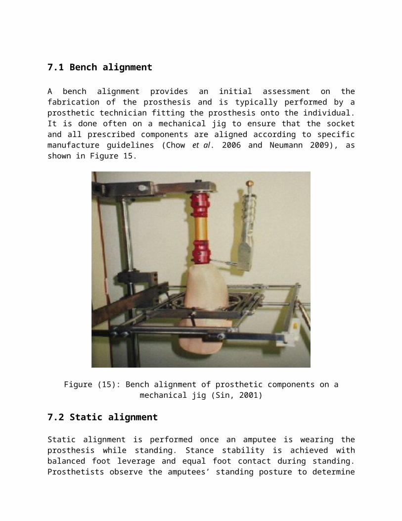
A bench alignment provides an initial assessment on the fabrication of the prosthesis and is typically performed by a prosthetic technician fitting the prosthesis onto the individual. It is done often on a mechanical jig to ensure that the socket and all prescribed components are aligned according to specific manufacture guidelines (Chow et al. 2006 and Neumann 2009), as shown in Figure 15.
Figure (15): Bench alignment of prosthetic components on a mechanical jig (Sin, 2001)
7.2 Static alignment
Static alignment is performed once an amputee is wearing the prosthesis while standing. Stance stability is achieved with balanced foot leverage and equal foot contact during standing. Prosthetists observe the amputees’ standing posture to determine if they are off balance. For example, the amputee is working hard not to fall backwards, the foot may be too plantar flexed or the socket too posteriorly titled. Prosthetists also observe if the pelvis is level in the frontal plane and adjust the length of the prosthesis as needed. In some cases, prosthetists have access to instruments such as the Laser Assisted Static Alignment Reference system (LASAR), which is intended to aid the statistic alignment process by quantifying the standing balance of the amputee in terms of variables such as the Centre of pressure (COP) or the weight line. Although static alignment sets a reference position of various prosthetic component parts under stable conditions, it does not give any prediction of the person’s gait characteristics during locomotion. This can be achieved through dynamic alignment.
7.3 Dynamic alignment
Dynamic alignment is performed on the amputee’s prosthesis during locomotion. A variety of gait characteristics are examined through both the prosthetics’ and physical therapists’ observation of the amputees’ gait as well as the amputees’ feedback. The aim is to meet the amputees’ biomechanical needs and produce a safe and effective gait pattern by adjusting and offsetting the various prosthetic components from static alignment position without compromising standing stability. Apart from achieving a correct and effective gait pattern, dynamic alignment also aims to reduce sensational discomfort and energy expenditure during walking, and to improve cosmetic appearance. For these reasons, dynamic alignment appears to be the most imperative alignment stage, since it is the final step of the alignment process and determines the final position of the prosthetic components. It affects not only the amputees’ locomotion but also their static posture. For this reason, this study focused on dynamic alignment. When it comes to evaluating this alignment process, several studies have explored techniques to aid prosthetics in achieving more effective alignments. In 1986, Mizrahi et al conducted a study to assess successful fitting through a combination of gait analysis, a 10-meter walk test and camera recordings. This study found that alignment decisions were based on a combination of factors, including the participants’ preferences and the prosthetics’ subjective judgments; therefore, a wide range of alignment variations were obtained. Subsequently, a neural network aided system was developed to acquire force/moment data and to recognize patterns of misalignment automatically. However, since the device was tested on only one subject, its outcomes were susceptible to subject-dependency and the need of prolonged training. A decade later, Geil et al. (2004) examined a device called planar pedoarography, where the Centre of pressure was traced from foot pressure measured by an in-shoe pressure sensor. They concluded that foot pressure distribution exhibited significant changes with alignment modifications and that good alignment changes could increase prosthesis support during gait if given sufficient adaptation time (e.g. seven to ten steps minimal). Nonetheless, this device was very expensive and difficult to set-up for measuring the direction of locomotion, the starting point, and the number of steps per trial. In short, there exists a need for a dynamic alignment instrument that is less expensive and can produce more objective and consistent alignment results. More recently, Neumann (2009) conducted a thorough review of transtibial prosthetic alignment studies done over 35 years (from 1973 to 2008) and found 34 articles with 43 outcome measures. Neumann evaluated each outcome measure and gave a confidence level to each. Almost all studies were done with experienced amputees (over 1 year after amputation) in a controlled environment, which means that the range of acceptable alignments would likely decrease if other walking surfaces were considered. Only three out of the 34 studies recruited more than ten participants, and no indication of randomizing trials to avoid learning effects was reported. The author of this review accorded only moderate confidence in most of the results from these studies. The mechanism of the contralateral knee (e.g. maximum knee flexion) was identified as a potential indicator of misalignment; however, this parameter cannot be easily measured clinically. More research is needed to identify new kinetic and kinematic variables as good indicators of misalignment.
8. EFFECTS OF A PROSTHETIC MISALIGMENT
Gait deviation effects The typical gait cycle of a healthy person is depicted in Figure 16. The cycle begins at heel-strike and ends at the subsequent heel-strike of the same limb. A gait cycle is composed of two parts: a) stance phase and b) swing phase. The stance phase is the period when the limb touches the ground and supports the body. The swing phase is the latter half of the gait cycle where the limb is in the air not bearing any weight (Winter, 1990 and Fang et al. 2009). A gait deviation, defined as any walking pattern that departures from a smooth and natural gait, may be expected in the case of a prosthetic misalignment.
Figure 16: A typical gait cycle
Prosthetic gait is complex. Reasons leading to transtibial gait deviations can be caused by intrinsic or extrinsic factors. Intrinsic factors are the individuals’ medical or psychological states and/or their locomotors adaptations. Extrinsic factors may include socket fit, comfort, prosthetic alignment settings and/or environmental conditions. Transtibial alignment settings refer mainly to the positions of the socket in relation to the prosthetic foot. Some examples of transtibial prosthesis misalignments and the dominant gait deviation that each could cause are presented in table 1 (Mensch, 1986 and Grumillier, 2008). Prosthetic gait is complex. Reasons leading to transtibial gait deviations can be caused by intrinsic or extrinsic factors. Intrinsic factors are the individuals’ medical or psychological states and/or their locomotors adaptations. Extrinsic factors may include socket fit, comfort, prosthetic alignment settings and/or environmental conditions. Transtibial alignment settings refer mainly to the positions of the socket in relation to the prosthetic foot. Some examples of transtibial prosthesis misalignments and the dominant gait deviation that each could cause are presented in Table 1 (Mensch, 1986 and Grumillier, 2008).
Table 1: Transtibial prosthetic settings and possible resulted gait deviations
Socket placed too anterior in relation to the foot, or foot set too posterior - in excessive dorsiflexion.
Gait is accelerated during stance phase, causing excessive or early knee flexion from heel-strike to midstance or prior to toe-off.
Like walking downhill, greater heel strike impact causing pelvic drop and shoulder drop on the prosthetic side to recover balance.
Socket placed too posterior in relation to the foot, or foot set too anterior - in excessive plantar flexion.
Gait is slowed at the end of stance phase, causing insufficient or delayed knee flexion from heel-strike to midstance and from midstance to toe-off.
Like walking uphill, greater forefoot push required causing hip abduction on the prosthetic side and vaulting on the sound side to reduced spinal rotation.
Socket placed too far lateral in relation to the foot, or foot set too far medially - in excessive eversion
Excessive varus or medial moment.
Pelvic drop or shift laterally on the sound side to center the weight over the socket.
Socket placed too far medially in relation to the foot, or foot set too far laterally - in excessive inversion
Excessive valgus or lateral moment and knock knees effect.
Residual limb drawn toward midline or pelvic bend laterally toward the prosthetic side to avoid discomfort.
9. Transtibial Prosthesis Model
Locations for alignment change
It is important to note that when prosthetists make alignment adjustments, screws could be turned at two locations along the vertical alignment axis: the below-socket or the ankle level. They would either perform a rotation/tilt by adjusting screws at only one location as shown in Figure 6 (b), or a translation/shift by adjusting screws at both locations as shown in Figure 6 (c), where foot is always flat on the ground.
Figure 17: Screw adjusting locations for tilt or shift alignment change (a) Base position of a neutral alignment; (b) A tilt: one angular change done at the below-socket location; (c) A shift: one angular change done at the below-socket location and an opposite angular change done at the ankle location. The foot is always flat on the ground.
SUMMARY of prosthetic alignment
Dynamic prosthetic alignment is an essential process for gait rehabilitation of individuals with transtibial amputations. Conventionally, a dynamic prosthetic alignment is performed by prosthetists and is primarily based on the prosthetists’ experiences and 15 subjective assessments of the amputees’ gait patterns and feedback. Scarce instruments exist today to quantify and improve this alignment process. Instruments such as the Compass™ system could provide real-time biomechanical measures and potentially serve as an objective aiding tool for prosthetists conducting the dynamic alignment of transtibial prosthesis. To date, no studies have assessed the benefits or performance outcomes of the Compass™ system. Would the Compass™ system produce sufficiently better alignment results compared to the conventional technique used by prosthetists? This is the primary focus of this research project.
10. WEIGHT BEARING AND BALANCE
10.1 Partial weight bearing (two-hand support)
It is important to ensure that the patient performs the exercises accurately, always maintaining the correct posture
Figure (18) Step1: Stand between the parallel bars using both hands to support yourself. Step2: Shift the body weight from the sound leg to the prosthesis (a pair of scales may be useful to measure the weight shifted).
10.2 Partial weight bearing (one-hand support)
Figure (19) Step 1: Stand between the parallel bars using one hand to support you. Step 2: Shift the body sound leg to the prosthesis. Always use the contralateral hand.
10.3 Partial weight shift (two-hand support)
Step 1 Step2 k22
Step1 22
Step2 22
Figure (20) Step 1: Stand between the parallel bars on both legs using both hands to support you.
Step 2 222222
Step 1 222222
Step 2: Shift the pelvis forward and backward, without moving your shoulders.
10.4 Partial weight shift (one-hand support)
Figure (21) Step 1: Stand between the parallel bars on both legs using one hand to support you. Step 2: Shift the pelvis forward and backward. Always use contralateral hand
10.5 Partial weight shift (without support)
Figure (22) Step 1: Stand between the parallel bars on both legs without support.