CASE STUDIES ON THE REHABILATION OF HISTORIC BRIDGES Requested by: American Association of State Highway and Transportation Officials (AASHTO) Center for Environmental Excellence Prepared by: The SRI Foundation Rio Rancho, New Mexico July 5, 2011
Transcript
CASE STUDIES ON
THE REHABILATION OF HISTORIC BRIDGES
Requested by:
American Association of State Highway
and Transportation Officials (AASHTO)
Center for Environmental Excellence
Prepared by:
The SRI Foundation
Rio Rancho, New Mexico
July 5, 2011
i
ACKNOWLEDGEMENTS
The Center for Environmental Excellence by AASHTO (Center) wishes to acknowledge the following individuals and agencies for providing the information on the case studies included in this report. Florida
Transystems: M.A. Lahti, Mary McCahon, and J.J. Pullaro URS: Jose Polo
Indiana
Butler, Fairman, & Seufert, Inc.: Jonathon Sera and Stephen Weintraut Maryland
Maryland State Highway Administration: Maurice Agostino, Daniel Beck, Danelle Bernard, Anne Bruder, and Greg Roby
Minnesota
Mead & Hunt, Inc.: Dusty Nielsen, Christina Slattery, and Amy Squitieri Oregon
Oregon Department of Transportation: Benjamin Tang Pennsylvania
Pennoni Associates Inc.: William Cameron Pennsylvania Department of Transportation : Matthew Hamel, Monica Harrower, Thomas Nevinger, Jeff Raykos, Kara Russell, Narayan Velaga, and Ryan Whittington
Texas
Texas Department of Transportation: Bruce Jensen, Ann Maxwell, Mario Sánchez, and Charles Walker
Virginia
Virginia Transportation Research Council: Ann Miller West Virginia
West Virginia Department of Transportation: Courtney Fint, Ben L. Hark, and Sondra Mullins Wisconsin
Cedar Corporation: Dennis Mack, Shawn Patnode, and Greg Wolfe Mead & Hunt, Inc.: Dusty Nielsen, Christina Slattery, and Amy Squitieri Wisconsin Department of Transportation: Robert Newbery
We also wish to thank the members of the Center for Environmental Excellence by AASHTO Historic Bridges Community of Practice for their assistance in preparing and reviewing this report.
ii
TABLE OF CONTENTS
ACKNOWLEDGEMENTS ............................................................................................................. i TABLE OF CONTENTS................................................................................................................ii LIST OF TABLES .........................................................................................................................iii LIST OF FIGURES........................................................................................................................iii INTRODUCTION........................................................................................................................... 1 CASE STUDIES ............................................................................................................................. 3
STONE ARCH BRIDGES......................................................................................................... 3 Johns Burnt Mill Bridge (Adams County Bridge No. 56), Mount Pleasant and Oxford
Townships, Pennsylvania ........................................................................................................ 3 Prairie River Bridge (aka Merrill Bridge or First Street Bridge), Merrill, Wisconsin .......... 7
CONCRETE ARCH BRIDGES............................................................................................... 10 Carrollton Bridge (Carroll County Bridge No. 132), Carroll County, Indiana ................... 10 Robert A. Booth (Winchester) Bridge, Douglas County, Oregon ......................................... 14
MOVABLE SPAN BRIDGES................................................................................................. 17 Bridge of Lions, St. Augustine, Florida................................................................................. 17
METAL TRUSS BRIDGES..................................................................................................... 21 Tobias Bridge, Jefferson County, Indiana ............................................................................ 21 New Casselman River Bridge, Grantsville, Maryland .......................................................... 23 Walnut Street Bridge, Mazeppa, Minnesota ......................................................................... 27 Pine Creek Bridge, or Tiadaghton Bridge, Clinton and Lycoming Counties, Pennsylvania 30 Washington Avenue Bridge, Waco, Texas............................................................................. 33 Lone Wolf Bridge, San Angelo, Texas................................................................................... 37 Goshen Historic Truss Bridge, Goshen, Virginia ................................................................. 40 Hawthorne Street Bridge, Covington, Virginia..................................................................... 45 Ross Booth Memorial Bridge (aka Winfield Toll Bridge), Putman County, West Virginia.. 49
METAL ARCH BRIDGES ........................................................................................................ 53 Lion Bridges (North and South), Milwaukee, Wisconsin ...................................................... 53
METAL GIRDER BRIDGES..................................................................................................... 57 Hare’s Hill Road Bridge, Chester County, Pennsylvania..................................................... 57
REFERENCES CITED................................................................................................................. 62 APPENDIX 1 ACRONYMS AND GLOSSARY........................................................................ 63
APPENDIX 2 LIST OF CASE STUDIES BY STATE............................................................... 72 APPENDIX 3 ADDITIONAL INFORMATION ON CASE STUDIES..................................... 73 APPENDIX 4 CASE STUDY INDEX ........................................................................................ 75
iii
LIST OF TABLES
Table 1. List of Historic Bridge Case Studies................................................................................. 2
LIST OF FIGURES
Figure 1. Johns Burnt Mill Bridge .................................................................................................. 3 Figure 2. Prairie River Bridge ........................................................................................................ 7 Figure 3. Prairie River Bridge ........................................................................................................ 8 Figure 4. Carrollton Bridge ........................................................................................................... 10 Figure 5. Carrollton Bridge ........................................................................................................... 11 Figure 6. Robert A. Booth (Winchester) Bridge ........................................................................... 14 Figure 7. Bridge of Lions .............................................................................................................. 17 Figure 8. Bridge of Lions .............................................................................................................. 17 Figure 9. Bridge of Lions .............................................................................................................. 18 Figure 10. Bridge of Lions ............................................................................................................ 18 Figure 11. Tobias Bridge............................................................................................................... 21 Figure 12. New Casselman River Bridge...................................................................................... 23 Figure 13. New Casselman River Bridge...................................................................................... 24 Figure 14. Walnut Street Bridge ................................................................................................... 27 Figure 15. Walnut Street Bridge ................................................................................................... 28 Figure 16. Pine Creek Bridge........................................................................................................ 31 Figure 17. Washington Avenue Bridge......................................................................................... 33 Figure 18. Washington Avenue Bridge......................................................................................... 34 Figure 19. Lone Wolf Bridge ........................................................................................................ 37 Figure 20. Goshen Bridge ............................................................................................................. 40 Figure 21. Goshen Bridge ............................................................................................................. 41 Figure 22. Hawthorne Street Bridge ............................................................................................. 45 Figure 23. Hawthorne Street Bridge ............................................................................................. 46 Figure 24. Ross Booth Memorial Bridge ...................................................................................... 50 Figure 25. Lion Bridges ................................................................................................................ 53 Figure 26. Lion Bridges ................................................................................................................ 54 Figure 27. Hare’s Hill Bridge........................................................................................................ 57 Figure 28. Hare’s Hill Bridge........................................................................................................ 58
1
INTRODUCTION In 2007, the National Cooperative Highway Research Program (NCHRP) published a report entitled “Guidelines for Historic Bridge Rehabilitation and Replacement” (NCHRP Project 25-25, Task 19). This report presents
...nationally applicable decision-making guidelines for historic bridges. The guidelines are intended to be used as a protocol for defining when rehabilitation of historic bridges can be considered prudent and feasible and when it is not based on engineering and environmental data and judgments. The guidelines include identification of various approaches to bringing historic bridges into conformance with current design and safety guidelines/standards, and the effect or implications of remedial action on historical significance (NCHRP Project 25-25, Task 19, March 2007, page vii).
This NCHRP report provides, for the first time, guidance for decision-making on historic bridge rehabilitation. The report, however, does not include specific examples or case studies on rehabilitation. Currently, transportation engineers and historic preservation professionals do not have ready access to historic bridge rehabilitation case studies and best practices. A compilation of case studies and best practices would provide detailed, technical, real-world examples that state Departments of Transportation (DOTs) and local transportation agencies could use in planning and executing rehabilitation projects. This would be of particular value given the increasing focus of state DOTs on maintaining infrastructure, which includes historic bridges. In an effort to address this need for real-world best practices, the Center for Environmental Excellence by AASHTO has compiled several historic bridge rehabilitation case studies from around the country. The case studies included in this report were developed in partnership with state DOTs and local transportation agencies, and their historic bridge rehabilitation contractors. The case studies in this report provide the following information:
Information on the Bridge:
• Before and After Photographs
• Bridge Information: o Name o Location and Description of Setting (e.g., in redeveloping rural area with active agriculture,
open spaces with conservation easement, modern suburban housing)
• Bridge Description (include date of construction; bridge type; number, length, type of main and
any approach spans; information on subsequent alternations, etc. For truss bridges, identify field
connections – pinned/riveted/welded.)
• Rehabilitation Project Information
• Date/Cost for Rehabilitation
• Project Designer
• Bridge Owner
• Source for Additional Information on Bridge (contact for state DOT or local transportation
agency/owner for more information or if have questions) Project Information:
• Significant Issues Associated with Project
2
• Project Description, Including Purpose and Need
• Lessons Learned It should be noted that some of the information categories listed above were not available for a few of the case studies. Table 1 lists the 16 case studies presented in this report. The case studies are organized by bridge type, and are in alphabetical order by state under each bridge type.
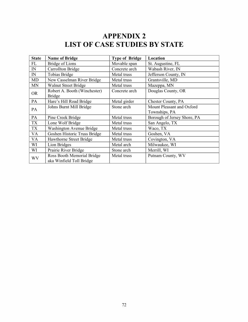
Table 1. List of Historic Bridge Case Studies
Type of Bridge Name of Bridge Location State
Stone arch Johns Burnt Mill Bridge Mount Pleasant and Oxford Townships, PA
PA
Stone arch Prairie River Bridge Merrill, WI WI
Concrete arch Carrollton Bridge Wabash River, IN IN
Concrete arch Robert A. Booth (Winchester) Bridge
Douglas County, OR OR
Movable span Bridge of Lions St. Augustine, FL FL
Metal truss Tobias Bridge Jefferson County, IN IN
Metal truss New Casselman River Bridge Grantsville, MD MD
Metal truss Walnut Street Bridge Mazeppa, MN MN
Metal truss Pine Creek Bridge Borough of Jersey Shore, PA PA
Metal truss Washington Avenue Bridge Waco, TX TX
Metal truss Lone Wolf Bridge San Angelo, TX TX
Metal truss Goshen Historic Truss Bridge Goshen, VA VA
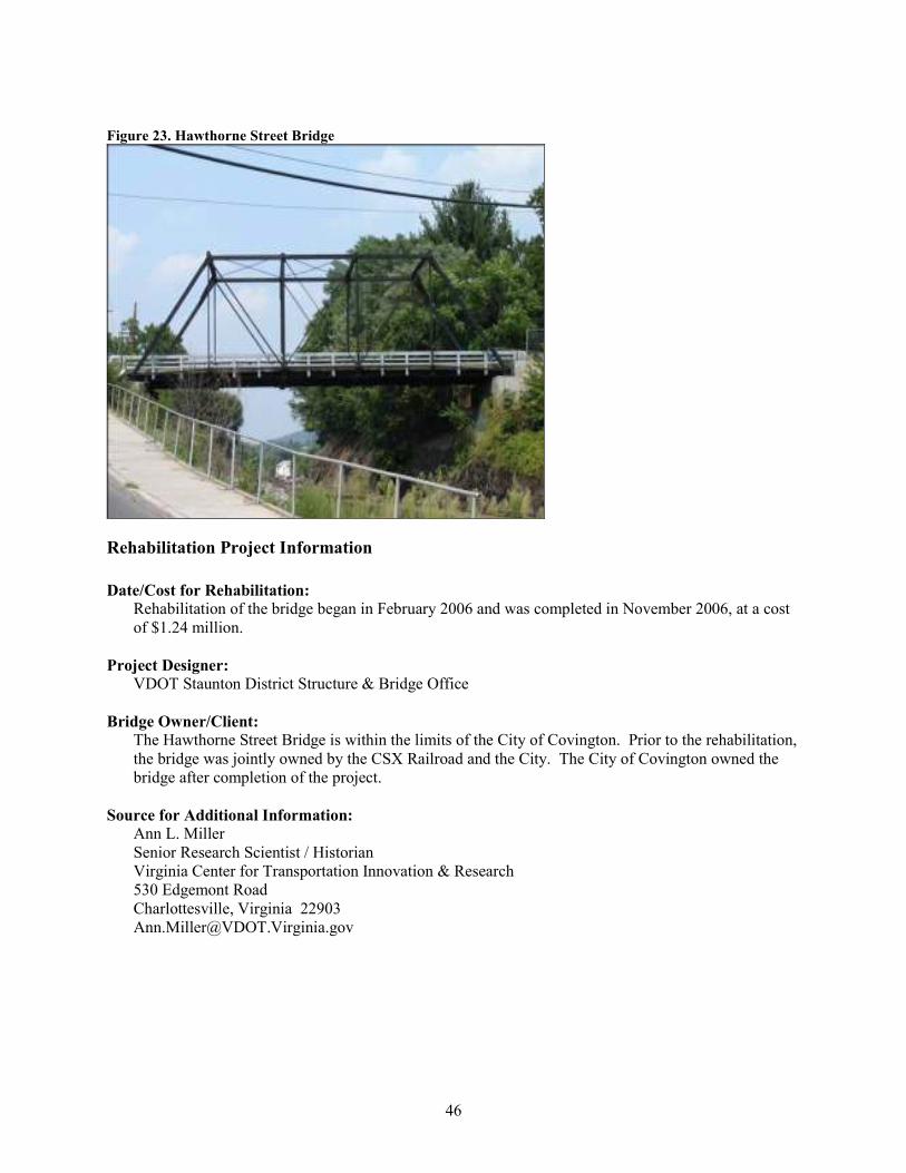
Metal truss Hawthorne Street Bridge Covington, VA VA
Metal truss Ross Booth Memorial Bridge aka Winfield Toll Bridge
Putnam County, WV WV
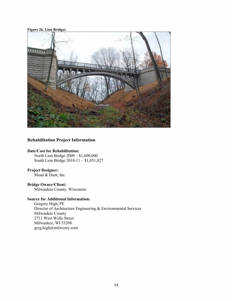
Metal arch Lion Bridges Milwaukee, WI WI
Metal girder Hare’s Hill Road Bridge Chester County, PA PA
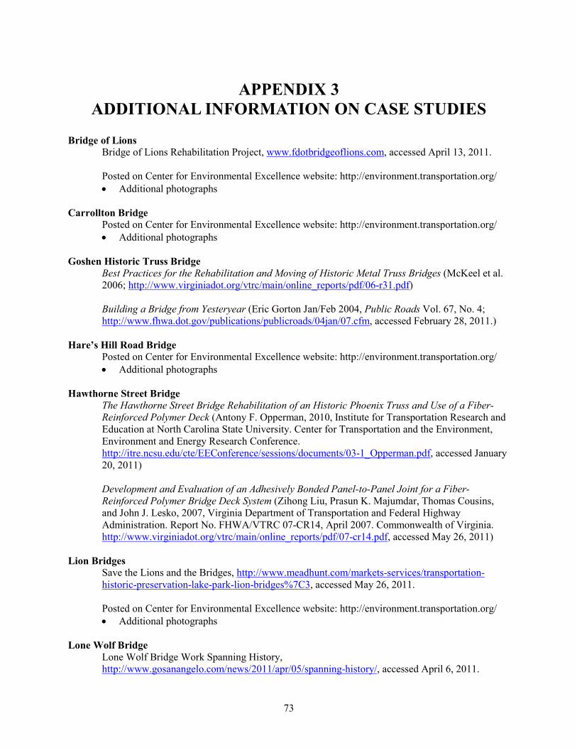
Appendix 1 of this report provides a list of acronyms and a glossary of terms. Appendix 2 includes a list of the case studies by state. Appendix 3 provides additional information on the case studies that was too voluminous to include in the body of this report. This additional information includes plans and schematics, additional photographs, drawings, etc. Appendix 4 is an index to the case studies.
3
CASE STUDIES
STONE ARCH BRIDGES
Johns Burnt Mill Bridge (Adams County Bridge No. 56), Mount Pleasant
and Oxford Townships, Pennsylvania
Location and Description of Setting:
The Johns Burnt Mill Bridge (Adams County Bridge No. 56) carries Storms Store Road over South Branch Conewago Creek, within Mount Pleasant and Oxford Townships, Pennsylvania. The bridge is located in a rural agricultural setting. A historic stone masonry mill building is located in the vicinity of the bridge.
Description of Bridge:
The Johns Burnt Mill Bridge, constructed in 1820, is a one-lane, three-span stone arch bridge. The bridge’s span lengths are 15, 18 feet, and 15 feet. The bridge width is 13 feet.
Figure 1. Johns Burnt Mill Bridge
Rehabilitation Project Information
Date/Cost for Rehabilitation:
The rehabilitation project was completed during the spring of 2006, at a cost of $840,000.
4
Project Designer:
Pennoni Associates, Inc. (Pennoni), Mechanicsburg, Pennsylvania.
Bridge Owner/Client:
Adams County, Pennsylvania. The rehabilitation was contracted by the Adams County Commissioners.
Source for Additional Information:
Paula V. Neiman Chief Clerk Adams County Commissioners 117 Baltimore Street, Room 201 Gettysburg, Pennsylvania17325 William D. Cameron, P.E. Adams County Bridge Engineer Pennoni Associates Inc. 1215 Manor Drive, Suite 100 Mechanicsburg, Pennsylvania 17055
Project Information
1. Significant issues associated with project (e.g., bridge condition, reasoning behind decision to rehabilitate versus replacement, reasoning behind selected maintenance activity).
In recent years, the bridge exhibited increased cracking in the arch barrels and spandrel walls, with a noticeable increase in cracking after a January 1996 flood. Inspection revealed that the fill above the arches had become saturated due to the flood waters. Freezing temperatures after the flood caused the saturated fill to expand, increasing the cracking in the arch barrels and spandrel walls. Scour of the stream bed at the piers also was observed during inspections.
Pennoni prepared a study of the alternatives associated with rehabilitating or replacing the bridge. The bridge is located in a Federal Emergency Management Agency (FEMA) floodway, so hydraulics were an important consideration in the alternatives study. The area is prone to flooding, and raising the profile grade of the roadway for a new bridge would have resulted in significant impacts to the floodway. The bridge is listed on the National Register of Historic Places (National Register), so replacement alternatives could result in adverse effects to this historic resource. Through the public involvement process, Pennoni learned that the majority of the residents of the area wanted to maintain the picturesque setting of the stone arch bridge. Cost comparisons indicated that a rehabilitation alternative was cost effective for both design and construction. Given these study results, rehabilitation of the historic bridge was deemed the appropriate decision.
2. Project description, including purpose and need.
The project began with a series of load tests, in addition to test borings into the bridge in order to determine the make-up and condition of the bridge’s foundations. Based on these tests, the project team decided to use precast concrete backing blocks to strengthen the arches. A structural analysis
5
demonstrated that installing the backing blocks would strengthen the bridge, eliminating the need for the existing 15 ton weight limit.
Construction plans for the rehabilitation project included:
• installing concrete aprons around the abutments, wingwalls, and piers;
• installing temporary centering to support the arches, and bracing to support the walls;
• removing the existing fill above the arches;
• installing the precast concrete backing blocks;
• installing a drainage system with weepholes;
• installing well-draining backfill;
• installing a heavy duty membrane;
• placing new bituminous pavement;
• repointing stone masonry;
• replacing the concrete parapet caps;
• installing new approach guide rail; and
• installing a standard one lane bridge signing.
3. Traffic levels, loading needs, and other related issues.
Traffic counts taken during 1995 and 2000 at the intersection of Storms Store Road and Stone Bridge Road, adjacent to the bridge, indicated that the number of vehicles per day (VPD) passing through the intersection was increasing approximately five percent per year. The current VPD is approximately 600, with no reported crashes in the vicinity of the bridge; however, a sharp vertical curve over the bridge, along with the single-file traffic flow across the bridge and its high parapet walls, created limited sight-distance.
After considering several alternatives, it was decided to rehabilitate the bridge with minimal approach roadway work. The approach roadways were improved, but not realigned. A new approach guide rail was installed, and the signage and pavement markings were upgraded, including the installation of new one-lane bridge signing. These improvements, while not extensive, were appropriate for the traffic volumes and speeds encountered at the intersection of Storms Store Road and Stone Bridge Road, and across the bridge.
4. Section 106 effects finding (no adverse, adverse). Major issues discussed with State Historic
Preservation Officer, and how issues were resolved.
The selected rehabilitation alternative resulted in a No Adverse Effects finding, in consultation with the Pennsylvania State Historic Preservation Officer (SHPO).
5. Lessons Learned.
It was important to first install the concrete aprons and to specify that the arches and walls be supported by temporary centering and bracing during construction. High water events occurred while the rehabilitation was underway and the arch fill had been removed. The in-place concrete aprons, false work, and bracings provided important temporary support during high water events when the bridge was in a vulnerable state due to the removed fill.
6
Periodic routine inspections of the bridge after completing the rehabilitation found no evidence of significant stone or mortar cracking or stone movement. These inspections demonstrated the value of using concrete backing blocks to strengthen the bridge.
7
Prairie River Bridge (aka Merrill Bridge or First Street Bridge), Merrill,
Wisconsin
Location and Description of Setting:
The Prairie River Bridge carries West Main Street over the Prairie River in the City of Merrill, Lincoln County, Wisconsin. It is located immediately east of the intersection of State Trunk Highway (STH) 64 and STH 107, near the T.B. Scott Library and the Stange Kitchenette Park. West of the bridge is Merrill’s western business district (the Stange Historic Area).
Description of Bridge:
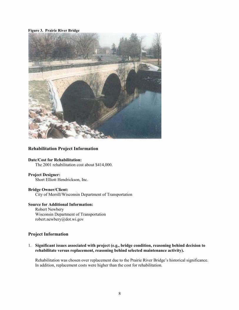
The Prairie River Bridge was constructed in 1904. The structure is a rubble-granite, pedestrian and vehicular bridge with three identical segmental arches rising 13 feet above the waterline. The bridge is about 130 feet long and 55 feet wide. Each arch has a decorative pattern of alternating, single and double ring stones with tapered keystones about 30 inches in height. The bridge features the longest series of arches of any stone-arch highway structure in the state. It is the only remaining three-arch stone bridge in Wisconsin. The bridge was first rehabilitated in 1951. The 1951 work did not significantly change the bridge’s architectural integrity. The stone railings were replaced with metal railings; and, the deck was re-concreted, widened slightly, and surfaced with bituminous material, requiring the removal of the tracks and brick pavers.
Figure 2. Prairie River Bridge
8
Figure 3. Prairie River Bridge
Rehabilitation Project Information
Date/Cost for Rehabilitation:
The 2001 rehabilitation cost about $414,000. Project Designer:
Short Elliott Hendrickson, Inc.
Bridge Owner/Client:
City of Merrill/Wisconsin Department of Transportation
Source for Additional Information:
Robert Newbery Wisconsin Department of Transportation [email protected]
Project Information
1. Significant issues associated with project (e.g., bridge condition, reasoning behind decision to
rehabilitate versus replacement, reasoning behind selected maintenance activity).
Rehabilitation was chosen over replacement due to the Prairie River Bridge’s historical significance. In addition, replacement costs were higher than the cost for rehabilitation.
9
2. Project description, including purpose and need.
The 2001 rehabilitation of the Prairie River Bridge included the use of an architectural form liner on the concrete parapets to match the stonework on the arches. The form liner was topped with a steel railing. The stonework was also tuck pointed, with some of the stones needing to be reset. A new sidewalk was placed on the bridge, along with new asphaltic pavement.
3. Section 106 effects finding (no adverse, adverse).
Wisconsin DOT determined that the proposed rehabilitation would result in No Adverse Effect the historic bridge. The Wisconsin SHPO concurred with this finding.
4. Lessons Learned.
It is important to have historic preservation experts involved in all stages of a rehabilitation project, establishing the roles and responsibilities of these experts prior to project initiation, in addition to how they are to coordinate their work with the work of other project personnel. Another lessons learned is the need to have a pre-construction meeting with all project personnel. This meeting should include a thorough review of inspection reports and proposed project action items. There also needs to be an agreement on whether to duplicate/replicate replacement elements, and whether or not non-visual elements need to use the same or similar materials as currently found on the bridge.
10
CONCRETE ARCH BRIDGES
Carrollton Bridge (Carroll County Bridge No. 132), Carroll County,
Indiana Location and Description of Setting:
The Carrollton Bridge carries Carrollton Road over the Wabash River, approximately three miles north of Delphi, Carroll County, Indiana. The bridge is in a rural, agricultural setting. The bridge was the first permanent crossing of the Wabash River. It is also the site of a historic Wabash and Erie Canal lock.
Description of Bridge:
The Carrollton Bridge was designed by Daniel B. Luten and was constructed in 1927. It is a 615 foot reinforced concrete arch bridge comprised of six spans.
Figure 4. Carrollton Bridge
11
Figure 5. Carrollton Bridge
Rehabilitation Project Information
Date/Cost for Rehabilitation:
The project began in May of 2005 and the bridge was reopened to traffic in December of 2006. Final construction was completed in the summer of 2007. The construction cost was $1,916,750.
Project Designer:
Butler, Fairman, & Seufert, Inc. Contractor: Wirtz and Yates, of Kentland, Indiana
Bridge Owner/Client:
Carroll County, Indiana
Source for Additional Information:
Stephanie Wagner Bridge Rehabilitation Engineer Indiana Department of Transportation—Central Office
Project Information
1. Significant issues associated with project (e.g., bridge condition, reasoning behind decision to rehabilitate versus replacement, reasoning behind selected maintenance activity).
The Carrollton Bridge is a National Register-listed concrete arch bridge that was once considered too deteriorated and obsolete to be saved. Through the use of innovative engineering techniques, special materials, and experienced construction inspection engineers, the bridge was saved and rehabilitated. The exterior appearance of the bridge did not change significantly from the original form, although
12
the deck was widened by four feet and the arch strengthened for heavy loads. The use of relatively new materials and engineering techniques, such as self-consolidating concrete, steel-backed timber approach railings, composite deck brackets, and modified Texas Type “T-411” bridge railings, helped make the project a success. Since the existing bridge is listed in the National Register, it was extremely important that the external appearance of the structure not change any more than absolutely necessary. Due to the extreme deterioration of the pier shafts from freeze/thaw action, complete encasement was required as part of the rehabilitation. Self-consolidating concrete was used in the encasement of the piers in order to reduce the thickness of the encasement and to provide a more uniform appearance for the concrete surface. The use of this material was a first for the Indiana DOT LaPorte District.
The new cantilever brackets that support the new concrete deck were two feet longer than the existing brackets, but the depth and width were kept the same so as to not significantly change the exterior appearance of this historic structure. The new concrete deck was made composite with the brackets to provide full-load capacity for the longer cantilever, and deck reinforcement was concentrated over the beams so it could contribute to the load capacity of the cantilevers.
Incorporating a new continuous deck composite with the brackets and spandrel walls has an additional benefit. It helps distribute the load over a larger area, increases the load capacity of the arch rings, and stiffens the bridge against heavy truck loads. It also creates a concrete roof over the arch fill, thereby eliminating the ingress of moisture into the substructure and reducing the concrete’s deterioration due to freeze/thaw action.
The existing railing could not be replaced “in kind” and still meet current federal guidelines for crash tested bridge railing. Therefore, the Texas Type “T-411” railing was heavily modified to provide a similar appearance to the existing rail, but still providing the necessary strength and geometry to satisfy Federal Highway Administration (FHWA) crash standards. Thus, the railing emulated the look of the existing railing and meets crash test requirements.
2. Project description, including purpose and need.
The Carrollton Bridge provides a major river crossing for Carroll County residents, farmers, and commuters traveling to and from the city of Delphi. Very few structural repairs had been performed on this concrete arch bridge since its original construction in 1927. The bridge was considered functionally obsolete with a growing concern developing over the structural health of the bridge. Freeze/thaw damage was observed over much of the structure including the overhang brackets, pier stems, and arch rings. Concrete cracking and delaminations were resulting in section loss throughout the structure. Growing concerns over load capacity and the lengthy detour that would be necessary if the bridge had to be closed prompted county officials to initiate a replacement project. Funding shortfalls within the county government and mounting objections from state and local historical agencies, however, resulted in the decision to rehabilitate, rather than replace, the Carrollton Bridge. The purpose of the rehabilitation project was to address both functional and structural deficiencies of the bridge without significantly affecting the historical properties of the bridge.
3. Traffic levels, loading needs, and other related issues. The safety of the traveling public was greatly improved by increasing the width of the structure to 24 feet. The structure is no longer posted as a narrow bridge. The four feet of added bridge width also
13
reduces the driver/pedestrian conflicts that were frequent before the rehabilitation. Stoned shoulder sections at all four corners of the bridge and a public access location beneath the bridge’s north span allow people to park safely and enjoy a panoramic view of the area.
In addition to the added travelway width provided on the bridge, crash tested bridge and approach railings were constructed. This is an enormous safety improvement over the inadequate bridge rail and non-existent approach railing of the existing structure. The blunt concrete bridge rail ends on the original structure were considered a major hazard for today’s traffic volumes and speeds.
4. Section 106 effects finding (no adverse, adverse). Major issues discussed with State Historic
Preservation Officer, and how issues were resolved.
A meeting at the project site was held immediately after the project Notice to Proceed in order to streamline the coordination with the State Historic Preservation Office and other interested parties. The meeting included representatives from SHPO, Indiana DOT, the Indiana Historic Spans group, Wabash & Erie Association, Carroll County, and other parties. After much discussion regarding the needs and concerns of each group, a general consensus was reached regarding the general scope of the project. As a result of this meeting, coordination that would normally take several months to complete was finalized in a matter of days. The Indiana DOT made an Adverse Effect finding on the project, and worked with all of the parties to prepare a Memorandum of Agreement on resolving this adverse effect.
Progress meetings were held with all of the parties throughout the project. These meetings were helpful in keeping everyone informed, setting schedules, and meeting deadlines.
Because the Wabash and Erie Canal once crossed the Wabash River at this bridge location (remnants of old locks have been found at the northwest corner of the bridge), an interpretive sign explaining the history and functioning of the canal locks was installed at the north end of the bridge. A second interpretive sign discusses the history and significance of the Carrollton Bridge.
5. Lessons Learned. First, it is important to look for ways to modify current standard bridge elements so they appear to match the originals bridge elements. In the case of the Carrollton Bridge project, by modifying the shape of the windows in a current crash tested standard railing, no design exceptions were required. The new railing emulated the look of the original railing, and also met crash test requirements. Second, careful detailing can ensure that the historical integrity of the bridge is not lost in rehabilitation and repair work. Extensive detailing of the bridge railing and overhang brackets ensured that the profile view of the bridge conformed to the consistent gradual curve of the original design. False work details for the overhang brackets used every third existing bracket to support the new brackets. This process helped retain the neat lines of the original bridge construction.
14
Robert A. Booth (Winchester) Bridge, Douglas County, Oregon
Location and Description of Setting:
The Robert A. Booth (Winchester) Bridge carries Oregon Highway Route 234 over the North Umpqua River, Douglas County, Oregon. It serves as direct access to several historic resources and recreation areas, including the National Register-listed Winchester Dam (ca. 1880), Amacher Park, the Oregon & California Railroad Corridor (ca.1870s), the 1904 Kolhagen Ranch House, and a historic steel bridge upstream. It also provides access to boat ramps and sport fishing along the river, and a fish ladder viewing area. The bridge accommodates pedestrians and bicycles as well as vehicular traffic.
Description of Bridge:
The bridge was built in 1924, and is one of the longest reinforced concrete ribbed deck arch bridge designed by Conde McCullough. The bridge is distinguished by its architectural design, which can be described as Tudor or Gothic in its details. The outstanding features of the bridge include the series of seven delicate arched spans and lancet-arched spandrel walls that support the deck and roadway, cantilevered balconies at the north and south end spans, and the lancet-arched balustrade railings that extend the length of the bridge. The bridge is 887 feet 8 inches in length (one span at 62 feet; seven at 112 feet; and one at 41 feet 8 inches).
Figure 6. Robert A. Booth (Winchester) Bridge
Rehabilitation Project Information
Date/Cost for Rehabilitation:
The bridge underwent a major rehabilitation in 2007 to provide additional roadway width for traffic and sidewalks for pedestrians while preserving its historic value and significant features. The rehabilitation project was completed in 2008 at $10 million.
15
Project Designer:
Hamilton Construction Co., Springfield, Oregon
Bridge Owner/Client:
Oregon Department of Transportation
Source for Additional Information:
Benjamin Tang Bridge Preservation Managing Engineer Oregon Department of Transportation [email protected]
Project Information
1. Significant issues associated with project (e.g., bridge condition, reasoning behind decision to rehabilitate versus replacement, reasoning behind selected maintenance activity).
There were two significant challenges with this project. One was a political challenge that addressed the extended closure time of the highway route. The design team demonstrated through their study that there were no good and feasible alternatives to closing the facility. As a result, funding was made available to relocate a fire and ambulance team to continue the required response time to the local community. Business consultants were brought in to assist the impacted businesses, helping them manage their operations during the bridge closure, thus minimizing their losses. The second big challenge involved drilling into the existing beams and deck sections and placing new steel where necessary. In the 1920s, not only was steel placement not as orderly as it is today, but the concrete cover varied and steel reinforcing hooks were placed randomly. A constructability review suggested the best approach for adding new steal was to drill into the existing steal. In hindsight, however, it might have been better to hydro-blast the beam sections and then place the new steel. This would have avoided the possibility of jeopardizing the existing steel.
2. Project description, including purpose and need.
The scope of this project included widening the structure’s roadway from 19 feet 4 inches to 24 feet; adding 11-inch raised curbs and three-foot sidewalks; repairing or replacing floor beams, deck and bridge rails; adding a deck drainage system; and reconstructing a retaining wall, an abutment endwall, and the bridge approaches. The new bridge rails are the Oregon “stealth” rails, which provide a structural steel, vehicle containment rail hidden within a precast concrete rail. To ensure long-term durability to the beam repair patches that were inaccessible for cleaning, a cathodic protection system was added. In this system, zinc puck acts as an anode to the steel reinforcement. Fiber-reinforced polymer composite wrapping was used to repair and strengthen concrete members that were weathered and deteriorated. A non-intrusive, visually hidden, deck drainage system was added to the bridge deck and sidewalks to control runoff at joints and bearings.
16
3. Section 106 effects finding (no adverse, adverse). Major issues discussed with State Historic
Preservation Officer, and how issues were resolved.
Oregon DOT made a finding of No Adverse Effect, based on the proposed rehabilitation, and the Oregon SHPO concurred with this finding. The SHPO noted that
“Project alternatives included a bypass alternative and various widening alternatives. It was found that keeping the bridge in service as a highway bridge would cause the least overall harm to the resource in the long term. The modest widening of the roadway deck and addition of sidewalks would decrease the roadway deficiencies while not compromising the structural integrity of the substructure.”
4. Lessons Learned. First, it is important to implement early coordination with all stakeholders and resource agencies. As part of applying a Context Sensitive Solutions (CSS) approach to the project, stakeholders were engaged early in the project and their input was incorporated into the project’s decision-making process. Second, seek public support for the rehabilitation project. The project team prepared extensive renderings for the public and resource agencies, showing the visual affects of the widening and restoration. The renderings were a key feature in demonstrating how the final product would fit within the context of the area’s historic resources. Third, carefully consider the experience of the project contractor. It is important to have an experienced contractor who can adapt current bridge standards to older structures. Fourth, develop a bridge preservation program and general policies for the program. The program should include long-term objectives, with funding support; sustainable program strategies; and a commitment to extending the service life of historic structures. The program should also include strategies for corrosion protection, corrosion resistance, and the use high performance materials. The Robert A. Booth Bridge rehabilitation project showcases how to restore and increase the safety, capacity, and load rating of an historic bridge that would otherwise be uneconomical to replicate in today’s business and public agency work culture. The project promotes the use of current and emerging bridge technologies, such as cathodic protection technique, fiber reinforced polymer composites, and restoration construction techniques. The project also demonstrates the successful use of CSS protocols and processes. It actively engaged stakeholders and community in order to obtain their support for the project.
17
MOVABLE SPAN BRIDGES
Bridge of Lions, St. Augustine, Florida Location and Description of Setting:
The Bridge of Lions crosses Matanzas Bay (part of the Intercoastal Waterway) and connects the city of St. Augustine with the resort communities of Anastasia Island, St. Johns County, Florida. It is located in an urban setting, with its western approach in the historic district of St. Augustine.
Description of Bridge:
The Bridge of Lions was designed by John E. Greiner and constructed in 1927. The bridge has a total length of 1,545 feet. The main span is a 95 foot double-leaf rolling lift bascule. Approach spans are steel arched girder-floorbeam spans with cantilevered overhanging sections.
Figure 7. Bridge of Lions
Figure 8. Bridge of Lions
18
Figure 9. Bridge of Lions
Figure 10. Bridge of Lions
Rehabilitation Project Information
Date/Cost for Rehabilitation:
The project was officially completed in January 2011, at a cost of around $20 million.
19
Project Designer:
Reynolds, Smith and Hills / Lichtenstein Consulting Engineers, Inc. Bridge Owner/Client:
Florida Department of Transportation
Source for Additional Information:
Roy A. Jackson State Cultural Resources Coordinator Florida Department of Transportation [email protected]
Project Information
1. Significant issues associated with project (e.g., bridge condition, reasoning behind decision to
rehabilitate versus replacement, reasoning behind selected maintenance activity).
This architectonic bridge is a significant feature of the historic streetscape of St. Augustine and is a gateway to the old city. The bridge was rehabilitated in order to retain its historically significant architectural features, while solving the bridge’s structural problems. This was accomplished by constructing a “bridge within a bridge.” Enough of the old bridge was retained to classify the project as a rehabilitation and not new construction. New construction would have required use of all modern design criteria.
2. Project description, including purpose and need.
Prior to rehabilitation, the bridge was in fair to poor condition, particularly in terms of the fracture critical girder-floorbeam approach spans and the substructure units. At many locations, crutch bents had been previously installed in order to provide additional support. As part of the rehabilitation, the bridge’s two fascia girders were retained for visual appearance, while new steel stringers were installed inside the girders. The fascia girders, which were removed, repaired, and then reset in place, were relieved of most of the loads and the new stringers now carry the majority of the dead load and the traffic loads. The stringers are hidden from view and will not distract from the architecturally significant arched girders. In addition, the approach spans were widened in order to improve the roadway geometry. The bascule piers and associated towers were left in place and repaired. This included replacing the existing concrete piers within the splash zone with new concrete, as the existing concrete contained high levels of chlorides. The bascule piers were strengthened by the addition of drilled shafts, and a new footing was placed below the existing waterline footing in order to provide sufficient strength for a modern design scour event.
Several features original to the bridge, but previously removed or replaced, were replicated. These included the pedestrian railing (with the height increased to meet modern standards), light standards, and rotating traffic gates. The bridge steel was painted to match the original bridge color.
3. Section 106 effects finding (no adverse, adverse). Major issues discussed with State Historic
Preservation Officer, and how issues were resolved.
20
The original bridge was recognized as important for its high artistic merit, rather than its technological significance. This made it possible to focus the rehabilitation on its historic character and appearance. This resulted in Florida DOT making a finding of No Adverse Effect. The Florida SHPO concurred with this finding.
4. Lessons Learned.
By retaining a sufficient amount of the existing bridge, this project was considered a rehabilitation. New construction would have required use of all modern design criteria, such as widening the navigable channel from the existing 84 foot to the 125 foot width now required for the Intracoastal Waterway.
To maintain the bridge’s historic character, it was extremely important to retain the design of the piers and the arch-shaped fascia beams, in addition to the cantilevered end sections of the girder-floorbeam approach spans. The fascia girders were reused on the slightly wider stringer approach spans, supported on substructure units that were rebuilt in-kind to the new geometry. The reused fascia girders support themselves and part of the bridge’s sidewalks.
21
METAL TRUSS BRIDGES
Tobias Bridge, Jefferson County, Indiana Location and Description of Setting:
The Tobias Bridge carries County Road 1350 West over Big Creek in Jefferson County, Indiana. The bridge is located on a one-lane, local road in a rural setting.
Description of Bridge:
The Tobias Bridge was fabricated in 1885 by the Indianapolis Bridge Company. It is a 154 foot-long, pin-connected wrought iron Whipple through truss bridge, and is the last metal truss bridge left in the county.
Figure 11. Tobias Bridge
Rehabilitation Project Information
Date/Cost for Rehabilitation:
The bridge was rehabilitated in 2004 for about $900,000 by Jefferson County.
Project Designer:
J. A. Barker Engineering, Inc.
Bridge Owner/Client:
Jefferson County, Indiana
22
Source for Additional Information:
James Olson Jefferson County Highway Engineer 300 East Main Street Madison, Indiana 47250 [email protected]
Project Information
1. Significant issues associated with project (e.g., bridge condition, reasoning behind decision to
rehabilitate versus replacement, reasoning behind selected maintenance activity).
The Tobias Bridge is the last remaining example of its type in the county. This prompted the county highway engineer and county commission to consider rehabilitation rather than replacement as a means to increase the bridge’s load carrying capacity, from three tons to 14 tons (the post-rehabilitation capacity).
2. Project description, including purpose and need.
The bridge’s low load carrying capacity was controlled by the light design of the verticals, composed of Z-shaped plate commonly used by the railroads. The challenge was to develop a way to increase their capacity and preserve their distinctive detail, as well as repair those that were bent or bowed. After considering several schemes, a decision was made to install additional plate to the outside of each vertical. The plates were connected using high strength button head bolts to keep the look of the original rivets, but at a lesser cost. Heat straightening was used to repair out-of-plane members. The historic look of the lattice railings inside the truss lines was preserved by welding them to modern tubular railings, providing an adequate safety feature that maintains a historic appearance. Cracked members in the ornamented portal braces were repaired, and the bridge was cleaned and painted.
3. Lessons Learned.
The county recognized the cultural value of the bridge and wanted it preserved and kept in service, and accepted that the end product would be a one-lane wide bridge with a 14-ton load carrying capacity. The county also retained a consulting engineer with a strong historic bridge rehabilitation record, and who had experience with developing practical ways to make truss bridges adequate while preserving historically significant details, like the Tobias Bridge’s unusual verticals. The project highlights several cost-effective rehabilitation techniques. Button head high-strength bolts were used instead of rivets as a more economical way to connect the new plates to the verticals. Heat straightening was used to bring members back into plane, demonstrating the cost effectiveness of this underused but cost-effect technique. Welding was used to repair cracks in the cast- and wrought-iron members in the portal braces, which, like the heat straightening, results in original fabric being conserved and preserved rather than replaced. The railings represent a practical solution by marrying old with new and providing a traffic railing that will also protect the truss lines.
23
New Casselman River Bridge, Grantsville, Maryland Location and Description of Setting:
The New Casselman River Bridge carries US 40 Alternate over the Casselman River in Grantsville, Garrett County, Maryland. To the north of the bridge is the old Casselman River stone arch bridge. This stone arch bridge was constructed in 1813 as part of the National Road, and resides in Casselman River State Park. To the south of the New Casselman River Bridge are the 1970s dual steel beam bridges carrying Interstate 68 over the Casselman River. Together the three bridges represent three generations of bridge and roadway construction. As such, the US 40 Alternate bridge represents a key element to the overall history of this area and the history of roadway/bridge construction.
Description of Bridge:
The New Casselman River Bridge was constructed in 1932 when the National Road was relocated from its original nineteenth-century location. It is a Pratt truss bridge with riveted connections. The bridge’s largest span is about 133 feet, and its total length is about 137 feet. The deck width is 40 feet and the vertical clearance above the deck is just less than 15 feet.
Figure 12. New Casselman River Bridge
24
Figure 13. New Casselman River Bridge
Rehabilitation Project Information
Date/Cost for Rehabilitation:
Detailed design work for this project started in 2006. The Maryland State Highway Administration (SHA) advertised the project in January 2008, and construction began in June 2008. The bridge was reopened to traffic in September 2008, and the project was completed in October 2008. The project was funded by Transportation Enhance Program Funds, Federal Bridge Rehabilitation Funds, and state funds. The total project cost was $2.5 million.
Project Designer:
Maryland State Roads Commission, Bridge Office. The Rehabilitation Design team for the New Casselman River Bridge included Maurice Agostino (Design Project Engineer, State Highway Administration Office of Structures), Steve Wiley (Construction Project Engineer, State Highway Administration District 6 Construction), Fred Braerman (Consultant Design Engineer, Johnson, Mirmiran and Thompson). The contractor was Concrete General, Inc.
Bridge Owner/Client:
Maryland State Highway Administration, Office of Structures Source for Additional Information:
Mauricio Agostino, Maryland State Highway Administration Office of Structures [email protected]
1. Project description, including purpose and need.
By 2006, when detailed design work for rehabilitation of the New Casselman River Bridge began, the bridge was classified as structurally deficient. The classification was due to the poor condition of the concrete deck and deterioration in some of the steel members that comprise the truss superstructure. A thorough inspection of every element was performed to determine the condition of the bridge and ascertain the feasibility of rehabilitating the bridge. The inspection revealed several areas where the steel portions of the bridge had corroded and were deteriorated to the point where entire steel members needed to be replaced or strengthened. While this was significant, the overall condition of the steel portions of the bridge was good. The primary area of concern was the concrete deck, which had full depth punctures and required constant attention. The design of the 80 year old bridge was reviewed using current bridge design code. Its design met today’s load carrying requirements. The bridge also provided sufficient lane and shoulder width for accommodating both vehicle and bicycle traffic. Therefore, despite the age of the New Casselman River Bridge, rehabilitating and repairing the bridge was determined to be the best course of action. The scope of the project included:
• replacing in-kind the concrete deck slab,
• repairing and strengthening a number of the truss vertical members,
• replacing a number of the truss diagonals,
• replacing the exterior stringers supporting the concrete deck slab,
• cleaning and painting the entire steel superstructure,
• minor repairs and modifications to the concrete abutments supporting the truss, and
• placing rip rap around the base of the abutment supports to protect against scour.
In order to perform the repairs to the steel truss superstructure, portions of the bridge needed to be disassembled. The bridge could not support vehicle traffic while this work took place, so during construction, the bridge was closed and traffic detoured. A comprehensive public involvement effort was undertaken to make sure all stakeholders affected by the detour were notified of the project and allowed to comment. The public involvement effort for this project included sending written notification of the project to businesses adjacent to the bridge, the Garret County School Board, local emergency services, and the elected officials in the area. A public informational meeting was also held. Particular attention was made to assure stakeholders that the bridge would be reopened to traffic prior to the Grantsville Fall Festival. Special considerations were made to accommodate pedestrians, bicyclists, and horse drawn vehicles from the local Amish community, which were not allowed to use I-68. A second detour via the older Casselman River stone arch bridge in Casselman River State Park was developed in conjunction with the Department of Natural Resources specifically to accommodate these users.
The New Casselman River Bridge was closed to traffic and the rehabilitation work commenced in June 2008. The concrete deck was removed and the rest of the bridge’s superstructure exposed. A second inspection of the bridge was performed at this time to identify any additional areas of deterioration not seen during the original inspection. This second inspection revealed only a few
26
additional areas that needed repairs, and confirmed that the steel superstructure was in good condition despite its age and exposure to the weather.
Construction progressed throughout the summer of 2008. After the concrete deck was removed, all old paint was removed from the steel superstructure and the deteriorated members of the truss were repaired or replaced in-kind. Once the steel repairs were completed, the new concrete deck was formed and placed, and all the steel portions of the bridge were painted. A new two strand metal railing was installed to serve as a traffic barrier. This barrier meets current safety standards and maintains an “open feel” as motorists travel across the bridge. A special shield/splash guard behind the railing protects the steel truss members from exposure to road salts and will help preserve the bridge. The bridge was reopened to traffic on September 15, 2008, meeting the SHA’s commitment to the community to reopen the bridge to traffic prior to the fall festival season. The service life of this bridge has been extended indefinitely as a result of the work performed.
The bridge continues to be used as a highway facility, while its historic character has been retained and preserved. The bridge’s distinctive materials and features were preserved through the careful repair on in-kind replacement of deteriorated elements. The shield/splash guard is a reversible addition that does not alter the historic character of the bridge.
2. Traffic levels, loading needs, and other related issues.
Inspection (as of November 11, 2008)
• Deck condition rating: Very Good (8 out of 9)
• Superstructure condition rating: Satisfactory (6 out of 9)
• Substructure condition rating: Satisfactory (6 out of 9)
• Sufficiency rating: 83.3 (out of 100)
Average daily traffic (as of 2006): 3,750 3. Section 106 effects finding (no adverse, adverse). Major issues discussed with State Historic
Preservation Officer, and how issues were resolved.
In 2007, SHA consulted with the Maryland SHPO. The agencies concurred that the project as designed would have No Adverse Effect on historic properties, including the New Casselman River Bridge and surrounding historic properties in Grantsville and the old Casselman River Bridge, which is a National Historic Landmark.
4. Lessons Learned.
The rehabilitation of the New Casselman River Bridge is one example of the work that SHA has done over the years to maintain its historic properties. In May 2009, the Maryland State Highway Administration received the Maryland Historical Trust’s Maryland Preservation Award for Stewardship of Historic Properties by a Government Agency. This was the first award given in this category.
27
Walnut Street Bridge, Mazeppa, Minnesota
Location and Description of Setting: The Walnut Street Bridge crosses the Zumbro River in Mazeppa, Wabash County, Minnesota. The bridge provides direct access from Mazeppa’s downtown area to a city park and ball fields.
Description of Bridge:
The Walnut Street Bridge, constructed in 1904, is a Pratt truss with riveted connections. The main span of the bridge is 118 feet.
Figure 14. Walnut Street Bridge
28
Figure 15. Walnut Street Bridge
Rehabilitation Project Information
Date/Cost for Rehabilitation:
The project took place in the summer of 2002. Total cost for the project was $455,000.
Project Designer:
Mead & Hunt, Inc.
Bridge Owner/Client:
City of Mazeppa, Minnesota Source for Additional Information:
Duane Hofschulte City of Mazeppa
Project Information
1. Significant issues associated with project (e.g., bridge condition, reasoning behind decision to rehabilitate versus replacement, reasoning behind selected maintenance activity).
The Walnut Street Bridge was converted to pedestrian use in 1978, but the bridge had been closed due to deterioration. The city wanted to preserve the bridge for continued pedestrian use, however, and as a result, initiated the structure’s rehabilitation. Load rating analysis confirmed that the bridge met AASHTO pedestrian load requirements. A new bridge railing was selected to blend with the historic appearance of the existing truss and comply with Minnesota DOT and AASHTO design requirements for bicycle use. A new timber bridge deck was selected to minimize load.
29
2. Project description, including purpose and need.
A detailed inspection was performed to assess current deficiencies and needed repairs. Deteriorated bridge bearings, truss members, stringers, piers, and abutments were replaced to address that safety concerns that had closed the bridge. Repairs to the bottom chord were field connected with hex head bolts. Button head bolts were used for the upper chord repair in areas visible to pedestrians. Temporary bracing was used to support the truss during the chord repairs. The timber deck and railing were also replaced. New abutments and lengthened approach spans were designed to alleviate erosion problems that resulted from the area’s steeply sloped banks. Formliners with architectural surface treatment and color staining were used on the new piers and abutments.
3. Traffic levels, loading needs, and other related issues.
The bridge rehabilitation was designed to meet AASHTO pedestrian and maintenance vehicle loads. 4. Section 106 effects finding (no adverse, adverse). Major issues discussed with State Historic
Preservation Officer, and how issues were resolved.
The rehabilitation plans were prepared and carried out in accordance with the Secretary of the
Interior’s Standards for the Treatment of Historic Properties (Weeks and Grimmer 1995). The Minnesota SHPO concurred with the Minnesota DOT that the project would have No Adverse Effect on historic properties since the rehabilitation was conducted in accordance with the Secretary of the Interior’s Standards.
5. Lessons Learned.
Pratt trusses, such as the Walnut Street Bridge, were a common, workhorse bridge on early twentieth-century roadways. This project shows that an abandoned bridge can be rehabilitated economically for a new use to forge a needed connection within a community. Agencies agreed to certain modern construction methods, including bolts and a concrete formliner, for cost savings. A standard Minnesota DOT pedestrian railing was an economical way to meet the project’s aesthetic and design requirements.
30
Pine Creek Bridge, or Tiadaghton Bridge, Clinton and Lycoming Counties,
Pennsylvania
Location and Description of Setting:
The Pine Creek Bridge, locally known as the Tiadaghton Bridge, carries River Road over Pine Creek, at the boundary between Clinton and Lycoming Counties, Pennsylvania. It is approximately 1.5 miles southwest of the Borough of Jersey Shore, Pennsylvania. Pine Creek drains into the Susquehanna River 4,500 feet to the southeast of the bridge. The area surrounding the bridge has a low population density and is predominately agricultural. The area on the west side of the bridge is the location of the Tiadaghton Elm, a local historic landmark.
Description of Bridge:
The Pine Creek Bridge was constructed by the Berlin Iron Bridge Company in 1889. It is a seven-panel through lenticular truss with the Warren pattern typical of such longer spans. On the top chord, the panels measure 41 feet between joints, while on the bottom chord between joints the panels measure 20 feet 6 inches. The bridge is made of wrought and cast iron with steel members and decking added in later renovations. The bridge spans 287 feet 8 inches between end posts, with 21-foot high endposts measured from their bases to their upper pin connections. The maximum distance between the upper and lower chords is 39 feet 8 inches near the center of the span. The endposts are roughly square in section and consist of three flat plates riveted to four angles. Their inner edges are open and secured by latticed straps. At the portals, the end posts are joined by a pair of riveted angles that are further strengthened by latticed arches joining the posts near the top.
The floor system consists of beams spaced at approximately 7 feet for the entire span length beneath stringers spaced at 3.5 feet, supporting a 5.25 inch open-grid steel deck. The top chords are built-up sections consisting of two web plates, a top plate, and lacing connected with angles. The lower chords are tension-resisting members made up of sets of eye-bars. The diagonals are built-up angle sections with lacing. The vertical hangers are two square rods. A mid-height rod spans the length of the structure.
31
Figure 16. Pine Creek Bridge
Rehabilitation Project Information
Date/Cost for Rehabilitation:
Rehabilitation is currently ongoing. Project Designer:
McFarland Johnson Mark A. Hugaboom, PE http://www.mjinc.com/bridgesProject2.html
Bridge Owner/Client:
Pennsylvania Department of Transportation (PennDOT) Source for Additional Information:
Virginia Feigles-Karr Project Manager Pennsylvania Department of Transportation
Project Information
1. Significant issues associated with project (e.g., bridge condition, reasoning behind decision to
rehabilitate versus replacement, reasoning behind selected maintenance activity).
Rehabilitation was advanced as an alternative to replacement, in part, because of the high probability and cost of archaeology within the project area. A new bridge on a new alignment would have had significant impacts on the floodplain surrounding the existing truss, and would have impacted archaeological sites located within the floodplain.
32
2. Project description, including purpose and need.
The purpose of this project was to provide a crossing of Pine Creek that would satisfy the area’s transportation needs for an extended period of time, while recognizing the historical significance of the bridge and the nearby Tiadaghton Elm. The bridge was classified as functionally obsolete due to its narrow width (16 feet 11 inches), which required the bridge to be single lane. Its primary structural members, the trusses, limited the bridge’s width. The bridge also had an open steel deck which, especially in wet conditions, could result in vehicle tire slippage and loss of directional control. In addition, like all truss bridges, the Pine Creek Bridge features supported members adjacent to the roadway; if not adequately protected by a structural barrier, these could be damaged by a crash on the bridge. The non-redundant design of the truss could result in complete collapse of the span if a major support member were sufficiently damaged.
The vertical alignment approaching the bridge was also substandard, causing vehicles’ undercarriages to frequently contact the pavement. The vertical alignment also resulted in inadequate sight distance for vehicles.
3. Traffic levels, loading needs, and other related issues.
River Road is classified as a rural collector, and traffic counts conducted on August 2, 2000 indicate an Annual Average Daily Traffic (ADT) of 892 vehicles. The results of an Origin and Destination Study revealed that the majority of travelers crossed the bridge more than once a day and their main travel purpose was either work (36 percent) or social (25 percent). No significant development in the project area was expected in the foreseeable future. As a result, the future (design year) traffic in the no-build condition was forecast to exhibit little if any increases over existing traffic volumes.
Farmer surveys indicated their concern with the weight restriction placed on the bridge. Because of this weight restriction, farmers could not cross the bridge with some types of equipment, such as heavy tractors, loaded wagons, combines, and tractor trailers. At the time of the survey it was determined that an acceptable limit would be a 25 ton combination limit.
4. Section 106 effects finding (no adverse, adverse). Major issues discussed with State Historic
Preservation Officer, and how issues were resolved.
Based on a field view with personnel from the Pennsylvania SHPO, and subsequent coordination with the SHPO and FHWA, it was determined that the selective replacement and augmentation of truss components with high-strength steel would result in No Adverse Effect on the historic bridge.
After the bridge was dismantled, and further deterioration was discovered, the project contractor, PennDOT personnel, and FHWA maintained ongoing coordination with the SHPO to identify solutions consistent with the original project finding.
5. Lessons Learned.
Frequent field visits and communication between PennDOT, the project contractor, FHWA, and the SHPO was essential to addressing unanticipated issues such as the deterioration of truss components.
33
Washington Avenue Bridge, Waco, Texas Location and Description of Setting:
The Washington Avenue Bridge spans the Brazos River in downtown Waco, McLennan County, Texas. It is located 200 yards west of the Waco Suspension Bridge (built in 1870 and listed in the National Register in 1970). Built for two-way traffic, both traffic lanes on the Washington Avenue Bridge now run in one direction (southwesterly), carrying vehicular traffic. Pedestrian traffic continues in both directions.
The area surrounding the Washington Avenue Bridge is predominately flat, with a sharp drop at the riverbank. The bridge is level with the elevation of the surrounding roads. The river, on average, is approximately 380 feet wide and 20 feet deep. A public park encompasses the riverbanks in the vicinity of the bridge.
Description of Bridge:
The Washington Avenue Bridge, built in 1902, is a pin-connected, steel Pennsylvania through-truss. The length of the main span is 450 feet. Two approach spans measure 67 feet on the east side and 40 feet on the west, resulting in a total length of 557 feet. The total width, including roadway and sidewalks, is 41.5 feet. At its highest point, the truss is 60 feet above the road surface. The bridge was listed in the National Register in 1996. Currently in excellent condition, the Washington Avenue Bridge maintains a high degree of historic integrity. The bridge derives its significance as an excellent example of pin-connected, Pennsylvania truss bridge in the State of Texas. At the time of its construction, the Washington Avenue Bridge was the longest single-span truss bridge in the southwest. Today, the bridge is the longest and oldest single-span vehicular truss bridge still in use in the United States. The bridge contains a high percentage of original material and is still used for its intended purpose.
Figure 17. Washington Avenue Bridge
34
Figure 18. Washington Avenue Bridge
Rehabilitation Project Information
Date/Cost for Rehabilitation:
Rehabilitation took place in 2009, at a cost of $4,791,712.
Project Designer:
The design for the rehabilitation was done by the Texas DOT (TxDOT) in-house Bridge Division team.
Bridge Owner/Client:
The City of Waco, Texas
Source for Additional Information:
Charles Walker Senior Bridge Design Engineer Bridge Division Texas Department of Transportation 125 E.11th Street Austin, Texas 78701 [email protected]
35
Project Information
1. Significant issues associated with project (e.g., bridge condition, reasoning behind decision to rehabilitate versus replacement, reasoning behind selected maintenance activity).
The condition of the bridge prior to rehabilitation was “Fair condition – minor deterioration of structural elements (extensive).” The weakest element of the bridge was the superstructure, which was rated as being in fair condition. The main problems were fractured eyebars in the main truss, as-built capacity of several truss members significantly understrength for the required operating loading, and extensive corrosion of metal below the level of the deck.
2. Project description, including purpose and need.
In 2009, the City of Waco and the TxDOT rehabilitated the Washington Avenue Bridge for continued vehicular and pedestrian use. The purpose of the project was to provide a safe and efficient crossing of a vital link between two city streets. The need for the project included the safety concerns for the deterioration of steel members and concrete approaches of the bridge. A paint analysis determined the bridge historically was black, so it was returned to its original color. The rehabilitation included:
• removing the traffic railing and replacing it with a new crash tested rail,
• removing the concrete deck and sidewalk and replacing them with a new concrete deck and sidewalk,
• repairing or replacing steel bridge members (less than five percent of original materials replaced),
• cleaning and painting all material (metal painted black; concrete washed), and
• reinstalling and painting the existing pedestrian bridge rail.
3. Traffic levels, loading needs, and other related issues.
In the final recommendations after the most recent inspection, the Washington Avenue Bridge was approved for continued use with a gross loading limitation of 32,000 lbs., and a maximum axle or tandem load of 21,000 lbs.
4. Section 106 effects finding (no adverse, adverse). Major issues discussed with State Historic
Preservation Officer, and how issues were resolved.
TxDOT, in consultation with the Texas SHPO, determined that the rehabilitation resulted in No Adverse Effect. A major issue was the proposed lighting for the bridge. The issue was resolved by replacing existing cobra fixtures with new bell-shaped fixtures and arms in the same locations at the same wattage. This approach is similar to what was done on other historic bridges in Texas that required lighting.
5. Lessons Learned.
To achieve the best results for historic preservation, informal coordination and on-going consultation between all parties is extremely important. TxDOT continually consulted with the city and SHPO both before work began, and as unexpected design needs occurred during construction.
36
For example, early in the project an issue arose over the procedure and detail for replacing the existing sub-tie eyebars. The original design specified cutting the eyebar from the upper pin and installing the replacement with a welded detail. At the lower connection, however, the eyebar was to be extracted by unstacking the pin pack, followed by restacking the pin pack using a new eyebar having a conventional eye detail. The project contractor proposed using a welded detail for the lower connection similar to the upper connection detail, but modified to adapt to the specific problems of the unprotected lower connection. By avoiding unstacking and restacking the pin, the potential for damaging adjacent members was reduced. After much discussion, the contractor, TxDOT, and the SHPO determined that this work would replace the historic details in a sympathetic manner and in accordance with the Secretary of the Interiors Standards for the Treatment of Historic Properties (Weeks and Grimmer 1995). The visual difference was minor since the detail is about 40 feet above the deck of the bridge. The proposed approach was therefore suitable for both engineering and preservation goals.
As a result of the close access afforded by construction scaffolding, other conditions were discovered during construction that warranted changes to the work as planned:
• After blast cleaning, excessive corrosion of several pin-bearing plates was discovered. Analysis for a retrofit of the corroded plates also revealed that some of the uncorroded pin plates were understrength as originally designed. Retrofits were designed and installed for both conditions.
• After cleaning and installation of the sub-ties was completed, close inspection of all mid-pins was carried out. This revealed that the eyebars of the mid-span counters had slipped from the pin shoulders and were bearing on the pin threads. Using the procedures developed for detensioning the sub-tie eyebars, the project contractor was able to reset the counters. Another change involved installing a retainer clip detail to secure the connection.
The main lesson learned is that rehabilitation on a project of this complexity requires on-going engineering inspection, analysis, and design to detect and address conditions that may not be detectable until after cleaning and deconstruction have begun. Cooperation between the design engineer, the construction engineer, and the project contractor is essential to take full advantage of the construction process and maximize the long term preservation potential for the structure.
37
Lone Wolf Bridge, San Angelo, Texas Location and Description of Setting:
The Lone Wolf Bridge crosses the South Concho River in San Angelo, a small town in Tom Green County, West Texas.
Description of Bridge:
The Lone Wolf Bridge was commissioned by the newly created State Highway Department in 1921 to replace an earlier structure. The bridge consists of a single-span, steel, riveted through-truss bridge of the Pratt type, with 14 cast-in-place reinforced concrete approach spans. The main span is 152 feet, the overall length is 586 feet and the width is 26 feet. The metal truss and reinforced concrete approach spans were designed in-house by the Bridge Section of the Highway Department. As such, it is one of the earliest examples of public sector bridge designs carried out by a trained staff of civil servants for the State. The truss span was fabricated by the Virginia Bridge and Iron Company of Roanoke, Virginia (organized in 1895) and erected by Brown and Abbott Company. The large ashlar stone piers from the earlier structure were capped with formed concrete and reused to support the 1921 truss. A cantilevered metal sidewalk was added in the 1930s, and a forced sewer main was attached to the sidewalk some time later. The bridge was determined in 1995 to be eligible for listing in the National Register, and in the Texas Statewide Inventory of Metal Truss Structures.
Figure 19. Lone Wolf Bridge
38
Rehabilitation Project Information
Date/Cost for Rehabilitation:
The rehabilitation project began in the spring of 2010, and is now 70 percent complete, with an expected completion date of October 2011. The final project cost is estimated to be between $758,781 and $774,450.
Project Designer:
TxDOT’s in-house Bridge Division team
Bridge Owner/Client:
City of San Angelo
Source for Additional Information:
Mario Sánchez Historical Architect Environmental Affairs Division Texas Department of Transportation 125 E. 11th Street Austin, Texas 78701-2483 [email protected]
Project Information
1. Significant issues associated with project (e.g., bridge condition, reasoning behind decision to rehabilitate versus replacement, reasoning behind selected maintenance activity).
The Lone Wolf Bridge had been replaced with a new structure in the 1980s. This project was to convert the bridge at its present location to pedestrian traffic and link the structure to existing hike and bike trail along the river.
2. Project description, including purpose and need.
The purpose of this project was to convert the bridge to pedestrian traffic and link the structure to existing hike and bike trial along the river. Converting the bridge required replacing or repairing various elements. Replacements of the outside concrete girders were recast according to their original configuration. Steel member repairs were made using bolts of the same diameter. The historical bridge markers were cleaned and painted. The 1930s pedestrian walkway was removed, and its handrail repaired and re-used in the truss portion of the bridge. The bridge was painted, and new lighting, which visually complements the structure and is not intrusive, was installed. Finally, a sewer line that had been attached to the outside of the bridge was relocated to the north side of the structure within the deck area. The boxed sewer line required a higher rail height, and the rails on both sides were replaced to avoid having different heights.
39
3. Traffic levels, loading needs, and other related issues.
When completed, the bridge will be designed for an AASHTO pedestrian load of 85 psf, with an
4. Section 106 effects finding (no adverse, adverse) Major issues discussed with State Historic
Preservation Officer, and how issues were resolved.
TxDOT determined that the project would have No Adverse Effect on the bridge, and the Texas SHPO concurred with this finding. The rehabilitation brought the Lone Wolf Bridge back to its 1921 appearance, except for the pipe modification, which was visible but not intrusive. The bridge’s structural profile was not changed because the new outside girders maintained their original dimensions.
5. Lessons Learned.
The Lone Wolf Bridge rehabilitation project did not repair the bridges outer girders, but actually replaced the girders for the long term preservation of the bridge. The SHPO realized that this was a unique opportunity to extend the life of the historic bridge, and concurred with replacing the girders rather than conducting a patch repair, which would have failed in the short term. The 1930s outer pedestrian walkway was removed, as it did not meet ADA standards and was redundant since the bridge was being converted to a pedestrian crossing. The 1930s walkway rail was re-used in the rehabilitation as a pedestrian rail in the truss portion of the bridge. The SHPO also concurred with this approach given the re-use of the rail, the fact that the pedestrian walkway and its attached sewer line were later additions, and the rehabilitation would restore the outer profile of the bridge to its original 1921 appearance. The project illustrates how a transportation agency and SHPO can work together to bring about an efficient rehabilitation that secures the long term preservation of a historic structure, and provides opportunities to rebuild several of its lost original features.
40
Goshen Historic Truss Bridge, Goshen, Virginia
Location and Description of Setting:
The Goshen Historic Truss Bridge, carries Route 746 across the Calfpasture River in Goshen, Rockbridge County, Virginia. The bridge joins the east and west sides of the small town and serves as the only access for emergency vehicles to some homes in Goshen.
Description of Bridge:
The Goshen Historic Truss Bridge was built in 1890 by the Groton Bridge Company. It is a two-span, eight-panel pin-connected Pratt through truss. It has an approximate total length of 261 feet. The trusses are approximately 139 and 121 feet long. Deck width is 19.4 feet, and the vertical clearance above the deck is 19.7 feet. Each of the two trusses supporting a span is non-redundant. The trusses and end posts are two upright channels connected with cover plates and lacing bars; and the posts are two vertical channels connected with latticing. The portal has an ornate cresting sign and end post finials as well as latticed portal struts. Lateral and sway struts are closely spaced with lacing bar sway braces. The bridge has a simple 2-pipe railing. The limestone substructure includes coursed, tooled ashlar masonry piers consisting of large limestone blocks. The abutments are coursed-tooled ashlar masonry. The Goshen Bridge is one of Virginia’s earliest multi-span truss bridges and is typical of late-nineteenth century factory-manufactured bridges. As originally designed, the structure included a lane for vehicular traffic, a lane for streetcars, and a cantilevered sidewalk.
Figure 20. Goshen Bridge
41
Figure 21. Goshen Bridge
Rehabilitation Project Information
Date/Cost for Rehabilitation:
Documentation of the history and structure of the bridge, and planning for a full rehabilitation of the structure took place over several years. Construction began in March 2001. The removal of the trusses began in June 2001 (the actual removal started with the erection of the false work beams, prior to June 2001). The last truss was removed in October 2001. Reassembly began in February 2002, and construction was completed in July 2002. The contract was awarded to Allegheny Construction of Roanoke, Virginia, for $2.1 million; the final cost was approximately $2.2 million due to change orders for additional work replacing additional lower chord members.
Project Designer:
Virginia DOT Staunton District Structure & Bridge Office
Bridge Owner/Client:
Virginia Department of Transportation (VDOT)
Source for Additional Information:
Ann L. Miller Senior Research Scientist / Historian Virginia Center for Transportation Innovation & Research 530 Edgemont Road Charlottesville, VA 22903 [email protected]
42
Project Information
1. Significant issues associated with project (e.g., bridge condition, reasoning behind decision to
rehabilitate versus replacement, reasoning behind selected maintenance activity).
The Goshen Bridge was in poor condition, with widespread corrosion and section loss in some of the structural members. Prior to 1948, its roadway had been reduced to a single lane, and posted for a load limit of six tons. Because of the load limit, the bridge was unable to accommodate various emergency and service vehicles to some homes in Goshen. Over the years, costly maintenance on the bridge had been deferred with the aim of eventually replacing the bridge with a modern structure. By the late twentieth century, inspection reports detailed the poor condition of the bridge. There were numerous areas of corrosion and section loss to steel members. The piers were missing mortar and substructure stones in various locations. The roller bearing devices were frozen, and some were displaced. In addition, debris was present on the bridge seats, on the connections, and between the stringers. Only one lane was open to vehicular traffic. The other lane, originally planned as a streetcar lane, had not had decking for at least 50 years, and there was attendant corrosion of the exposed members. VDOT considered several alternatives for the management of the Goshen Bridge: leave the structure as-is, document and demolish the bridge; preserve or restore the bridge in place or at a more appropriate location, or rehabilitate the bridge to meet current system needs. Several factors resulted in VDOT's decision to rehabilitate the structure. The Goshen Bridge is listed in the Virginia Landmarks Register and the National Register, and VDOT had committed to preserving its historically-significant bridges whenever possible. There also was strong local pressure to preserve the bridge as an important landmark and to keep it in service. These factors contributed to the decision to rehabilitate the Goshen Bridge rather than replace it with a modern structure.
2. Project description, including purpose and need.
The VDOT Staunton District Structure & Bridge Office planned a full rehabilitation of the Goshen Bridge over several years, and in accordance with the Secretary of the Interior’s Standards for the
Treatment of Historic Properties (Weeks and Grimmer 1995). The plan was to repair and repaint the stone piers as needed, using compatible mortar. The truss was to be disassembled, and the members repaired as needed and galvanized. The truss was then to be reassembled and restored for two lanes of vehicular traffic. The project involved disassembling, reassembling, and rehabilitating the structure not only to continue to serve vehicular traffic but also to handle increased loads. VDOT personnel measured and photographed the bridge prior to its disassembly. Because the original drawings for the bridge no longer existed, new blueprints were created. Rehabilitation included the disassembly of the bridge, replacement of elements weakened by section loss or not fabricated to meet modern design specifications, galvanizing of the members to provide lasting protection, and reassembly of the restored substructure. Based on the findings of the field inspection, the design team determined that more than 100 structural components needed to be replaced. These components included all endposts, hip verticals, upper chord members, counters, and pins, as well as the floor beams, stringers, and deck. Radiographic and ultrasonic testing was conducted to ensure the suitability of all fracture-critical tension members designated for reuse in the reconstructed trusses. Tension control (round head) bolts, placed with the round head on the visible face of the structure, were to be used in the reconstruction of the structure. All of the structural steel,
43
including the bolts and bearings, was galvanized. Modern construction equipment allowed modification of the dismantling and erection processes at the bridge site, including the use of the internal falsework beam system rather than falsework bents at every panel point. Preserving the historical integrity of the Goshen Bridge was an important consideration. Rehabilitating the bridge required substantial replacement of members, but the original configuration of the bridge was maintained. The rehabilitation was controversial in part because it was more expensive than replacing the bridge with a modern structure. The technology and materials used to build truss bridges are no longer in use, however, and few people have practical experience building or repairing these bridges. Further, little information is readily available on safely and effectively identifying and performing necessary operations. To address this issue, VDOT’s Knowledge Management Division and the Virginia Transportation Research Council (now the Virginia Center for Transportation Innovation & Research) interviewed active and retired engineers, consultants, field personnel, environmental specialists, and architectural historians, and collected best practices related to pin-connected and riveted truss bridges.
3. Traffic levels, loading needs, and other related issues.
The structure was completely rehabilitated with two lanes of vehicular traffic and designed for the AASHTO H20-44 standard truck loading.
4. Section 106 effects finding (no adverse, adverse). Major issues discussed with State Historic
Preservation Officer, and how issues were resolved.
VDOT, in consultation with the Virginia SHPO, determined that the proposed rehabilitation would have No Adverse Effect on the historic bridge.
5. Lessons Learned.
The lessons learned from the Goshen Bridge project were:
• The disposition of a historic truss depends on its suitability for continued service in the transportation system, and its evaluation as a historic property. Local support is critical to the success of these projects.
• Successful restoration or rehabilitation of a historic truss is best accomplished through a partnership that includes historic resource personnel, bridge engineers, and the project contractor.
• Rehabilitation of the Goshen Bridge to carry modern loads cost much more than a conventional replacement structure, requiring funds beyond those available for normal maintenance replacement. Funding for a rehabilitation or restoration project must be in place to ensure its success.
• The first step in dismantling the Goshen Bridge was a detailed field inspection of the condition of the truss members, identifying the presence of lead paint, and measuring the general dimensions of the bridge and its site. Because the rehabilitation included the reassembly of the truss with the replacement of members, the inspection included detailed measurements of the dimensions of every member in the bridge. This level of documentation was essential in order to analyze the loads and determine stresses in the truss members.
• The detailed inspection and structural analysis of the bridge was critical. The project team also recognized that, to ensure worker safety, it needed to exercise sufficient care in properly supporting the truss.
44
• Project plans included those items needed to facilitate bidding and ensure proper completion of the project. It is also useful to include a suggested sequence of construction, details of the falsework system, any limitations on the size and weight of worker access systems, and any needed information on the layout of the existing bridge, in addition to details of the rehabilitated structure.
• The Goshen Bridge was constructed prior to the development of standard specifications for structural steel. For the rehabilitation project, samples from the truss members were tested to provide data on the strength and the weldability of the steel.
• The Secretary of the Interior’s Standards for Treatment of Historic Properties (Weeks and Grimmer 1995) were used to guide the rehabilitation. Members in the rehabilitated bridge complied with AASHTO specifications applicable to their planned use. This included pedestrian loading for the bridge. In addition, the rehabilitation’s field operations complied with environmental regulations of several local, state, and federal agencies.
• While the bridge trusses were dismantled, a falsework supported the structure. Generally, the falsework could be an internal beam system, a system of individual supports, or another approach suitable for the site. Each must be designed to carry safely the loads transferred from the trusses, and each must be in place to support the trusses completely prior to beginning dismantling operations.
• The location of members in the truss were marked in place before dismantling began. They were permanently die-marked prior to any treatment, including lead paint removal, after the truss was dismantled.
• Depending on the size of the structure and the extent of the movement required, modern construction equipment may allow for the removal and transport of a structure from its site with little or no dismantling,
• By applying the principles of preventive maintenance to bridges determined to be truly significant, their deterioration – and thus the costs of their restoration or rehabilitation – can be minimized, facilitating the preservation of important historic properties for future generations.
45
Hawthorne Street Bridge, Covington, Virginia Location and Description of Setting:
The Hawthorne Street Bridge, in downtown Covington, Alleghany County, Virginia, crosses three C&O/CSX railroad lines. The bridge serves parts of downtown Covington north of the railroad. During periods of high water, it is the only lifeline into this part of the city and thus must support emergency vehicles.
Description of Bridge
The Hawthorne Street Bridge was constructed ca. 1885–1890. It is a 75-foot clear span historic Pratt through truss bridge with Phoenix columns. It has a roadway width of 22 feet, and the span length is 81.0 feet. The deck width is 22.0 feet, and the vertical clearance above the deck is 14.3 feet. Five 15-foot bays are transversely supported by 14 by 119 foot girders. The six inch thick reinforced concrete deck between the girders is supported by stringers on five foot centers. The bridge now rests on concrete abutments, indicating that the bridge was moved to its present location in the early twentieth century. The Hawthorne Street Bridge is one of five truss bridges in Virginia that use the patented Phoenix column. It is a contributing structure to National Register-listed Covington Historic District. The bridge is also recommended as individually eligible for listing in the National Register.
Figure 22. Hawthorne Street Bridge
46
Figure 23. Hawthorne Street Bridge
Rehabilitation Project Information
Date/Cost for Rehabilitation:
Rehabilitation of the bridge began in February 2006 and was completed in November 2006, at a cost of $1.24 million.
Project Designer:
VDOT Staunton District Structure & Bridge Office
Bridge Owner/Client:
The Hawthorne Street Bridge is within the limits of the City of Covington. Prior to the rehabilitation, the bridge was jointly owned by the CSX Railroad and the City. The City of Covington owned the bridge after completion of the project.
Source for Additional Information:
Ann L. Miller Senior Research Scientist / Historian Virginia Center for Transportation Innovation & Research 530 Edgemont Road Charlottesville, Virginia 22903 [email protected]
47
Project Information
1. Significant issues associated with project (e.g., bridge condition, reasoning behind decision to
rehabilitate versus replacement, reasoning behind selected maintenance activity).
In February 2001, after several large pieces of deck fell onto the railroad tracks, the city closed the bridge to make emergency repairs. The concrete sidewalk, whose weight is critical in the rating of the structure, also required rehabilitation. In 2004, the bridge was posted at seven tons with a recommendation to reduce the posting to five tons based on a recent load rating. VDOT and the City of Covington both wanted to upgrade the Hawthorne Street Bridge. Because the CSX Railroad owned the structure, however, recommendations for adaptive use (on- or off-site), transferring ownership, discontinuance, or abandonment were not applicable, and because the bridge is a two-lane through truss, a structural upgrade to DOT standards was not feasible. The road alignment at each approach also was problematic (steep and sharp curves) and did not meet modern standards. VDOT decided to rehabilitate the bridge superstructure with a new deck/stringer/floor-beam system and keep the historical thru-truss. The objective of the rehabilitation was to retain the historic cast iron Phoenix truss system while replacing the deck, floor beams, and stringers, thereby reducing the weight of the bridge and increasing its load capacity.
2. Project description, including purpose and need.
The 2001 inspection report indicated that the structure was in poor condition. The deck and sidewalk were badly deteriorated and needed replacement. The weepholes were clogged and the structure needed cleaning. The lower chord moved under stress, and the bearings appeared to be frozen with rust, putting strain on the bridge. In addition, the structure had shifted downhill. Also, all pinned connections appeared to be frozen with rust, and there was pack rust and section loss in various members. The stringers and bearing seats had deteriorated and exhibited areas of section loss. Further, the abutments were cracked, spalled, delaminated, and undermined VDOT used a fiber-reinforced polymer composite cellular deck system to rehabilitate the Hawthorne Street Bridge. The most important characteristic of this application was reducing the bridge’s self-weight, thereby raising the live load-carrying capacity of the bridge, by replacing the existing concrete deck with the fiber-reinforced polymer deck. The panel-to-panel connections were accomplished using full width, adhesively (structural urethane adhesive) bonded tongue and groove splices with scarfed edges.
3. Traffic levels, loading needs, and other related issues.
The most important characteristic of the deck/beam/girder replacement was the reduction in self-weight of the bridge. This increased the posting (originally posted at a maximum load of seven tons) to 20 tons, thus allowing for use by emergency vehicles.
48
4. Section 106 effects finding (no adverse, adverse). Major issues discussed with State Historic
Preservation Officer, and how issues were resolved.
VDOT, in consultation with the Virginia SHPO, determined that the proposed rehabilitation would have No Adverse Effect on the historic bridge.
5. Lessons Learned. The Hawthorne Street Bridge is the first bridge in Virginia to use a fiber-reinforced polymer deck for vehicle traffic. The installation of this innovative and lighter-weight deck expanded the capacity and life expectancy of the bridge. The bridge is now deemed safe for emergency vehicles use, and its historic structure has been retained. Lessons learned from this project were:
• The fiber-reinforced polymer bridge deck system is a lightweight and safe alternative to conventional reinforced concrete bridge decks.
• The construction of a full-scale model of two bays of the five-bay Hawthorne Street Bridge provided valuable insights into the constructability of the adhesive panel-to-panel connections. The fabrication of the actual deck joints went smoothly, validating the use of the developed protocol on other fiber-reinforced polymer deck installations.
• Based on results obtained during the laboratory testing of a two-bay model, this adhesive bonding technique has the necessary serviceability and strength characteristics to be used in other similar bridge deck replacements. Testing only subjected the deck to one source of degradation (repeated loads), and future research should focus on the performance of the fiber-reinforced polymer deck system when subjected to varying moisture and temperature environments.
• One disadvantage regarding the use of this bridge deck system is its cost. The cost per square foot of the bridge deck system is significantly greater than a conventional reinforced concrete bridge deck of similar strength and stiffness. The best uses of this fiber-reinforced polymer bridge deck system are ones where the weight savings offset the higher initial material costs.
49
Ross Booth Memorial Bridge (aka Winfield Toll Bridge), Putman County,
West Virginia
Location and Description of Setting:
The Ross Booth Memorial Bridge is located in Putnam County, West Virginia between the towns of Winfield and Red House. The bridge spans the Kanawha River. Formerly the Winfield Toll Bridge, the bridge was renamed in honor of Ross Booth in June of 2006. Mr. Booth worked as a carpenter on the Winfield Toll Bridge and also helped with the construction of many bridges located in the western section of I-64. It was on one of those bridges that Mr. Booth was injured thus ending his career as a carpenter. The superstructure replacement of the adjacent Winfield Overpass, which was opened to traffic in 1958, was also included with the rehabilitation of the Ross Booth Memorial Bridge.
Description of Bridge:
The Ross Booth Memorial Bridge was built in 1955 by the John F. Beasley Construction Company. The Vincennes Company fabricated the steel and Harrington and Cortelyou, Inc. was contracted to design the bridge. Originally, the structure opened as a toll bridge. Entrance ramps to the toll bridge were utilized until the nearby Winfield Overpass Bridge was opened to traffic.
The Ross Booth Memorial Bridge consists of a three-span cantilever through-truss, flanked to the south by four 76-foot long continuous composite wide flange beam spans. The north end of the truss is flanked by two new composite continuous plate girder spans 58 feet and 33 feet in length. The cantilever through-truss consists of two anchor spans, each 245 feet in length. The main span is 462 feet in length, between pier centerlines. The main span is comprised of two 128-foot cantilever arms and a 205-foot suspended span. Truss members are made up of built-up or rolled steel sections. All truss connections are riveted except for the hangers and false chord members, which are pinned. The truss floor system consists of four longitudinal steel stringers that frame into transverse steel floorbeams at each lower panel point of the truss.
The structure is supported by reinforced concrete stub abutments and reinforced concrete rigid frame piers. The abutments and approach span piers are on steel piling, while the piers supporting the truss spans are on shale and gray sandstone. The approach span piers are double column open type frame piers, while the truss span piers have partial height concrete web walls. A five foot-wide concrete sidewalk runs along the bridge’s downstream side, bordered by a rectangular parapet with an aluminum handrail, while an F-Style parapet with an aluminum handrail borders the upstream side of the bridge.
In the 1980s the bridge’s navigation lighting system was replaced. In 1991, a latex modified concrete overlay was placed on the original bridge deck. In 1997 and 1998, several deteriorated steel cross beams were replaced and several deteriorated steel stringer webs were plated.
As noted above, the Winfield Overpass Bridge was opened to traffic in 1958. The two-lane structure over West Virginia 817 (formerly US 35) is a three span (44 foot, 82 foot, and 44 foot) continuous steel structure with four longitudinal steel beams, for an overall length of 174 feet from centerline to centerline of the abutment bearings.
50
Figure 24. Ross Booth Memorial Bridge
Rehabilitation Project Information
Date/Cost for Rehabilitation:
The Ross Booth Memorial Bridge underwent a major rehabilitation in 2010 at the cost of approximately $15,220,500.00. This rehabilitation included the superstructure replacement of the Winfield Overpass Bridge and some additional road widening on West Virginia 817.
Project Designer:
The Ross Booth Memorial Bridge was rehabilitated with design plans by URS Consulting Engineers. Orders Construction Company of St. Albans, West Virginia conducted all construction work. This company also conducted the rehabilitation of the Winfield Overpass Bridge.
Bridge Owner/Client:
West Virginia Department of Transportation
Source for Additional Information:
Sondra Mullins West Virginia Department of Transportation Capitol Complex Building 5, Room 450 Charleston, West Virginia 25305 [email protected]
51
Project Information
1. Significant issues associated with project (e.g., bridge condition, reasoning behind decision to
rehabilitate versus replacement, reasoning behind selected maintenance activity).
One of the major concerns about the project was the timing of the bridge closure during rehabilitation. Several public meetings were held in order to obtain public input on a full closure of the bridge for a shorter project time-frame versus a partial closing, extending the project duration to two construction seasons. Additional meetings were held with emergency personnel and city officials. West Virginia DOT decided to close the bridge and finish the project as quickly as possible, within a single construction season. The alternative, to allow one-way traffic during construction, would have extended the project to three years.
2. Project description, including purpose and need.
The Ross Booth Memorial Bridge project consisted of the following:
• Replacing selected floor beams (transverse floor system beams)
• Replacing selected bearings
• Replacing the deck
• Cleaning and painting the existing truss to resemble the original paint color
• Adding a sidewalk with a new pedestrian railing
• Installing a redundant hanger system for the suspended middle span of the bridge
• Conducing substructure work on the abutments and piers The Winfield Overpass Bridge rehabilitation included replacing the superstructure and adding a sidewalk, while giving a greater vertical clearance. The overall objective of the rehabilitation projects was to improve the safety and longevity of the bridges.
3. Traffic levels, loading needs, and other related issues.
The bridges were originally designed for what are presently HS-20 trucks weighing 72,000 pounds. The replaced bridge elements on the bridge were designed for the current AASHTO LRFD live loads. This loading is a combination of HS-20 trucks and a lane loading of 640 pounds per foot.
4. Section 106 effects finding (no adverse, adverse). Major issues discussed with State Historic
Preservation Officer, and how issues were resolved.
The Section 106 process was initiated in May 2008 for the rehabilitation of the Ross Booth Memorial Bridge and the superstructure replacement of the Winfield Overpass Bridge. The West Virginia SHPO concurred with the West Virginia DOT determination that the two bridges were eligible for listing in the National Register. The West Virginia DOT, in consultation with the SHPO, determined that the proposed rehabilitation of the two structures would result in an Adverse Effect. This finding was based primarily on the SHPO’s concerns about the final railing design for the structures.
52
5. Lessons Learned.
The West Virginia DOT consulted with the SHPO early in the project development process. As a result, the DOT was able to quickly resolve the adverse effects to the bridges, and complete the project without any major issues.
53
METAL ARCH BRIDGES
Lion Bridges (North and South), Milwaukee, Wisconsin
Location and Description of Setting: The Lion Bridges, now called the North and South Lion Bicycle and Pedestrian Bridge, are located in the Lake Park Historic District, Lake Park, Milwaukee, Milwaukee County, Wisconsin. The North and South Lion Bridges are separated by a flat, grassy plateau between deep north and south ravines. Located along Lake Michigan, Lake Park was one of the first parks created by the Milwaukee Park Commission in the 1890s and was designed by Frederick Law Olmsted’s firm. The bridges are located near the historic Lake Park Lighthouse and Keeper’s House. The Park is listed in the National Register, the Wisconsin State Register of Historic Places, and is a City of Milwaukee Landmark.
Description of Bridge:
The North and South Lion Bridges, built in 1896-97, are single-span, open-spandrel, steel arch bridges that are virtually identical in design and construction. The arches are comprised of a pair of riveted plate girders with steel spandrel columns and floor beams. The steel arch spans have ornamental metal railings. The coursed limestone masonry abutments have open-balustrade stone railings that terminate in large stone statues of lions on the end. Originally two-lane vehicular bridges, the structures were modified and narrowed in 1966 to remove traffic lanes and create a pedestrian and bicycle bridge. As a result of the modification, the structures retained the original arch span length of 86.5 feet but have a new out-to-out deck width of 11.2 feet. The abutments retain the original bridge width of approximately 50 feet.
Figure 25. Lion Bridges
54
Figure 26. Lion Bridges
Rehabilitation Project Information
Date/Cost for Rehabilitation:
North Lion Bridge 2009 – $1,600,000 South Lion Bridge 2010-11 – $1,051,827
Project Designer:
Mead & Hunt, Inc. Bridge Owner/Client:
Milwaukee County, Wisconsin
Source for Additional Information:
Gregory High, PE Director of Architecture Engineering & Environmental Services Milwaukee County 2711 West Wells Street Milwaukee, WI 53208 [email protected]
55
Project Information
1. Significant issues associated with project (e.g., bridge condition, reasoning behind decision to
rehabilitate versus replacement, reasoning behind selected maintenance activity).
Designed by noted landscape architect Fredrick Law Olmsted in the late nineteenth century, Lake Park was one of Milwaukee’s earliest parks. The North and South Lion Bridges originally acted as a gateway for vehicular traffic into the park. The bridges acquired their name from the pairs of sandstone lions flanking each bridge. In 1966, the bridges were narrowed, limiting access to bicycle and pedestrian traffic. Prior to rehabilitation, the North and South Lion Bridges had suffered significant structural deterioration and some vandalism. The limestone abutments were crumbling, steel structural members were deteriorated, the abutment bearings were corroded, finial ornaments from the railings had been removed, and the signature lion statues were weathered and sporadically marred with graffiti. Specific deterioration issues included:
• Fascia blocks from the abutments and wingwalls were spalled/cracked, missing, or structurally unsound.
• Portions of the superstructure, deck, and rail exhibited signs of rust pitting, cracking, and corrosion.
• The concrete approaches had settled and cracked.
• The plateau had eroded, causing three of the original 12 bollards to either lean towards or fall into the adjacent ravine.
If left untreated the bridges would become safety problems for bicyclists, pedestrians, and other park users. In addition, taking no action could lead to the eventual destruction and/or demolition of contributing elements in the National Register-listed Lake Park Historic District. The rehabilitation and restoration of the bridges was necessary in order to maintain a cohesive park design.
2. Project description, including purpose and need.
The rehabilitation of the North Lion Bridge was completed in 2010 and the rehabilitation of the South Lion Bridge will be completed in early 2011. Funding prevented a larger single project that would have included both bridges; however, the engineering and construction of the two projects was almost identical. Both projects were reviewed by the Wisconsin SHPO and the City of Milwaukee Historic Preservation Commission. Historically sensitive and innovative techniques were used to facilitate a successful and sustainable rehabilitation of these structures. Abutment and wingwall restoration included removing and replacing unsound limestone blocks and any sound but cracked limestone, as necessary. Rather than replacing the one-foot-thick limestone abutments entirely, the stone repair included cutting back stone to sound material, and installing a stainless steel anchor to secure the new stone face. The project contractor acquired limestone from the Lannon quarry, which was listed on the receipt from the original 1896 construction. During construction, the steel arch superstructure was temporarily supported, one side at a time, while the abutments were rehabilitated and the abutment bearings were reconstructed. Cracks in the limestone fascia were filled with an epoxy resin grout to prevent further damage. The materials, methods, and equipment proposed for use in the repair work were demonstrated in test panels.
56
Rehabilitation of the superstructure included complete or partial in-kind replacement of steel superstructure elements with substantial section loss. In particular, the bearings, floorbeams, diaphragms, spandrel column plates, and gusset plates located below the ends of the deck and deck joints required extensive reconditioning or in-kind replacement. The longitudinal channel along the bottom of the deck also required replacement. Existing and new bridge elements were painted with the same existing color. The deck was replaced to facilitate bearing replacement and to allow easier access during repairs to the spandrel column base plates, longitudinal deck channel, floorbeams, and diaphragm members. Rehabilitation of the existing steel pedestrian railings included removing the rust pack between the joints, surface cleaning and preparation, and surface overcoating. Open parapet railings along the wings and abutments were cleaned to remove dirt and moss. The original finials, a floral shape connected at the base, were largely missing along the bridge railing. In order to minimize the openings in the railing, the replacement finials were fabricated based on historic plans with slight modifications. Each finial was slightly enlarged both vertically and horizontally to address safety concerns about bridge railing openings. The lion statues were cleaned using non-abrasive fabrics and solutions.
3. Traffic levels, loading needs, and other related issues.
The bridge rehabilitation was designed for pedestrian and bicycle use in a public park. 4. Section 106 effects finding (no adverse, adverse). Major issues discussed with State Historic
Preservation Officer, and how issues were resolved.
The rehabilitation plans were reviewed and approved by the SHPO and the Milwaukee Historic Preservation Commission. The SHPO concurred that plans for the South Lion Bicycle and Pedestrian Bridge would result in a No Adverse Effect finding. A condition of this concurrence was that the project rehabilitate the bridge in accordance with the Secretary of the Interior’s Standards for the
Treatment of Historic Properties (Weeks and Grimmer 1995). The North Lion Bridge rehabilitation was not subject to Section 106 but the rehabilitation plans were also reviewed and approved by the SHPO. The project masonry work adhered to the following guidelines: Preservation Brief #1 – Assessing
Cleaning and Waterproof Repellent Treatments for Historic Masonry Buildings (Mack and Grimmer 2000); Preservation Brief #2 – Repointing Mortar Joints in Historic Masonry Buildings (Mack and Speweik 1998); and Preservation Brief #6 – Dangers of Abrasive Cleaning to Historic Buildings (Grimmer 1979).
5. Lessons Learned.
The rehabilitation of these significant historic bridges required negotiation and coordination with multiple cultural-resource regulatory agencies, including the SHPO, City of Milwaukee Historic Preservation Commission, and the Milwaukee County Department of Parks, Recreation, and Culture. In addition, interested parties that did not have regulatory oversight were invited to comment on the project, including the Milwaukee County Historical Society and Lake Park Friends. This coordination was critical to the success of this rehabilitation project. The project was also successful, because it complied with the Secretary of the Interior’s Standards for the Treatment of Historic
Properties (Weeks and Grimmer 1995).
57
METAL GIRDER BRIDGES
Hare’s Hill Road Bridge, Chester County, Pennsylvania Location and Description of Setting
The Hare’s Hill Road Bridge carries State Route 1045 over French Creek near Kimberton, outside the Borough of Phoenixville, Chester County, Pennsylvania. Although Phoenixville is an urban community, the bridge sits in a rural setting.
Description of Bridge
The Hare’s Hill Road Bridge was built in 1869 by Thomas W. H. Moseley. It is the last known surviving example of Moseley’s lattice girder design. It has a single span length of 103 feet. The bridge’s appearance mimics that of a truss, while the structure behaves more like a tied-arch. It is best described as a Wrought Iron Lattice Girder Bridge. The structure has been documented by the Historic American Engineering Record, and is listed in the National Register.
Figure 27. Hare’s Hill Bridge
58
Figure 28. Hare’s Hill Bridge
Rehabilitation Project Information
Date/Cost for Rehabilitation:
The rehabilitated was conducted in 2010, at a cost of $826,690.
Pennsylvania Department of Transportation, Engineering District 6-0
Source for Additional Information:
Narayana R. Velaga Consultant Portfolio Manager (HNTB) Pennsylvania Department of Transportation, Engineering District 6-0 7000 Geerdes Boulevard King of Prussia, Pennsylvania 19406
Project Information
1. Significant issues associated with project (e.g., bridge condition, reasoning behind decision to rehabilitate versus replacement, reasoning behind selected maintenance activity).
While the Hare’s Hill Road Bridge’s original wrought iron lattice girders and floorbeams were in fair condition, the bridge was structurally deficient and functionally obsolete. Its structurally deficient determination was based not only on its load carrying capacity, but also on its physical condition. The steel stringers of the bridge had large holes in the webs near the ends due to advanced corrosion.
59
The open steel grid deck allowed water and de-icing chemicals to continuously wash over the stringers and floorbeams, which caused advanced deterioration of the stringers for the full length of the bridge.
The decision to rehabilitate the bridge rather than to replace it was based on two primary factors: the historic integrity of the bridge and the relatively low increase in projected traffic volume. Since the bridge was listed in the National Register, the first preference was to preserve the bridge. Traffic studies showed that while the area in general was expected to see significant growth and increased traffic, Hare’s Hill Road would be less affected because it is a local collector road that provides service between two arterials over a relatively short distance.
During the 1930s, Hare’s Hill Bridge was strengthened by the installation of additional floorbeams to compliment the existing floorbeams, although vertical members were not added at the additional floorbeams. By adding additional vertical members during the current rehabilitation project, the unbraced length of the top flange compression member was reduced, and thus improve its capacity. It also met the project goal to not adversely affect the historic appearance of the bridge.
Although the current open steel grid deck was in fair to good condition, it had to be removed in order to reach the deteriorated stringers. This provided the opportunity to replace the deck and install a larger curb to help prevent vehicles from impacting the fracture critical lattice girders, since most of the existing bridge’s vertical and diagonal tension rods exhibited minor collision damage.
2. Project description, including purpose and need.
The goal of the Hare’s Hill Road Bridge rehabilitation project was to preserve the historic structure and increase its useful life without adversely affecting its historic integrity. A secondary goal was to complete the rehabilitation at a reasonable cost, considering that when completed the bridge would still only accommodate a single lane of traffic.
At the start of the project, PennDOT had some rough hand and computer calculations on file regarding the bridge’s approximate load carrying capacity, but a detailed analysis of the structure had never been performed. Consequently, a conservative weight limit of seven tons was applied to the bridge. One consideration was to determine the true capacity of the existing structure and then determine feasible options to increase its capacity. An additional objective was to increase the load carrying capacity of the bridge such that local emergency service vehicles and school buses could use the bridge. Prior to the rehabilitation, school buses were detoured around the bridge resulting in additional travel time. Material testing was used to determine the real strength and physical properties of the original wrought iron components and the older steel elements. A three dimensional finite element model consisting of over one million elements was developed for the bridge and used to determine the stresses in each component. In order to confirm the accuracy of the finite element model, full-scale load testing was performed at the site. Several fully loaded dump trucks were weighed and placed on the bridge at various locations and at various speeds to produce maximum results in different members. The finite element model was then calibrated to achieve the results from the load testing. This provided a very high degree of confidence in the true capacity of this unique historic structure. The rehabilitation of the bridge involved adding new vertical members, and replacing damaged verticals, damaged end diaphragm stiffeners, deck, stringers, and bearings. In addition, the abutment beam seat and backwall was re-constructed and select portions of the field stone masonry abutments and wingwalls were re-pointed.
60
3. Traffic levels, loading needs, and other related issues.
Hare’s Hill Road had a current traffic volume of about 3,900 vehicles per day and this volume was projected to increase to about 5,000 vehicles per day by 2029. With a clear roadway width of only 14 feet 9 inches, there was only enough room on the bridge for one lane.
Structurally, PennDOT hoped to achieve a load rating that allowed fire trucks to use the bridge, which would require a capacity near the legal load of 36 tons. The existing weight limit of seven tons was increased to 15 tons as part of the rehabilitation project. Although it still cannot be used by fire trucks, it does allow school buses and other local delivery trucks to use the bridge.
4. Section 106 effects finding (no adverse, adverse). Major issues discussed with State Historic
Preservation Officer, and how issues were resolved.
At the start of the project, the project contractor met with the SHPO to come to an agreement on the type of work that could be done to the structure without changing its historical appearance. During these discussions, the SHPO noted that rehabilitation should not mimic the original appearance too closely. If a structural member was to be replaced and was originally connected using rivets, rivets should not be used for a replacement member. That way, in the future, there would be no confusion as to which parts were original and which parts had been replaced. Further, the proposed work should blend with the original construction.
During a public meeting on the project, concerns were expressed about the open grid steel deck. It was noted that the existing open grid deck would be replaced with a similar open grid deck. A local bicycle organization expressed concerns about the safety of crossing the steel grid deck. After some discussion, it was agreed that a four foot wide concrete strip would be placed down the center of the structure. This gave bicyclist and motorcyclist’s ample room to cross the structure safely. The SHPO concurred with the placement of a concrete strip on the bridge. During construction, an issue developed concerning the tension rods. The original tension rods had been hand-fabricated and a similar replacement member would take a long time to fabricate. The project contractor suggested replacing the rods with standard-shape members in order to expedite construction. A new connection piece, however, was required that did not match the original construction or the approved rehabilitation plans. This information was submitted to the SHPO and PennDOT for review. The SHPO noted that the new connection did not significantly change the appearance of the structure, and expressed appreciation at being involved in the decision-making process. PennDOT also concurred with the contractor’s proposed approach.
5. Lessons Learned.
One lesson for any historic bridge rehabilitation project is to involve all interested parties in the project as early as possible. For example, had the local bicyclists not had their concerns heard early, it would have been very difficult to add several tons of concrete to the bridge after the structural analysis was completed. The project engineer was able to effectively incorporate this feature into the preliminary design as a result of obtaining this request early in the consultation process.
Another lesson learned was the care needed in dealing with unique structural details. In particular, it is important to consult with specialty fabricators to determine what might be economically feasible. In addition, the value of material testing and load testing is immeasurable. Any bridge rehabilitation project that aims to determine or increase the load carrying capacity should be based on detailed
61
knowledge of the strength of the bridge materials. If as-built drawings are not available and industry standards cannot be used, the material properties should be determined from samples rather than working from assumptions about the materials. On the Hare’s Hill Bridge rehabilitation, the project consistently analyzed and evaluated the properties of the original wrought iron, which can be variable.
62
REFERENCES CITED Grimmer, Anne E. 1979 Preservation Brief #6 – Dangers of Abrasive Cleaning to Historic Buildings. Available online:
http://www.nps.gov/history/hps/tps/briefs/brief06.htm, accessed May 25, 2011. Mack, Robert C., FAIA, and Anne Grimmer 2000 Preservation Brief #1 – Assessing Cleaning and Waterproof Repellent Treatments for Historic
Masonry Buildings. Available online: http://www.nps.gov/history/hps/tps/briefs/brief01.htm, accessed May 25, 2011.
Mack, Robert C., FAIA, and John P. Speweik 1998 Preservation Brief #2 – Repointing Mortar Joints in Historic Masonry Buildings. Available
online: http://www.nps.gov/history/hps/tps/briefs/brief02.htm, accessed May 25, 2011. National Cooperative Highway Research Program 2007 Guidelines for Historic Bridge Rehabilitation and Replacement. NCHRP Project 25-25, Task 19.
Available online: http://onlinepubs.trb.org/onlinepubs/archive/NotesDocs/25-25(19)_FR.pdf Weeks, Kay D. and Anne E. Grimmer 1995 The Secretary of the Interior’s Standards for the Treatment of Historic Properties with Guidelines
for Preserving, Rehabilitating, Restoring & Reconstructing Historic Buildings. Available online: http://www.cr.nps.gov/hps/tps/standguide/, accessed May 25, 2011.
63
APPENDIX 1
ACRONYMS AND GLOSSARY
ACRONYMS
AASHTO American Association of State Highway and Transportation Officials. ADA Americans with Disabilities Act ADT Annual Average Daily Traffic – or – Average Daily Traffic Center Center for Environmental Excellence by AASHTO DOT Department of Transportation FEMA Federal Emergency Management Agency FHWA Federal Highway Administration H, HS Standard Highway Design loading designation for trucks LRFD Load Resistance Factor Design MOA Memorandum of Agreement NRHP National Register of Historic Places PennDOT Pennsylvania Department of Transportation SHPO State Historic Preservation Office, State Historic Preservation Officer. STH State Trunk Highway TxDOT Texas Department of Transportation VDOT Virginia Department of Transportation VPD Vehicles per day
64
GLOSSARY
INTRODUCTION
The following is a glossary of terms used in the case studies. The majority of bridge terminology
definitions are from AASHTO’s Standing Committee on Highways/Subcommittee on Bridges and Structures’ Bridge Terms Definitions (http://www.iowadot.gov/subcommittee/bridgeterms.aspx). If a term was not included in the latter, the following sources were used:
Glossary of Bridge Terminology derived from Chapter LXXX of J.A.L. Waddell’s 1916 Bridge Engineering, Lichtenberger Engineering Library, University of Iowa (http://sdrc.lib.uiowa.edu/eng/bridges/WaddellGlossary/gloss.htm)
Ohio Department of Transportation Bridge Inspector’s Reference Manual
In those cases where terms were not found in these three sources, definitions were taken from the following. In addition, definitions were obtained from the individuals providing the case studies:
Oregon Department of Transportation Office Practice Manual, Bridge Engineering Section, 2003 (http://www.oregon.gov/ODOT/HWY/BRIDGE/docs/OPM/sect1_03.pdf?ga=t,),
Slab, Beam & Girder Bridges in Oregon: Historic Context Statement, by George Kramer, M.S., HP, Heritage Research Associates, Inc., prepared for Oregon Department of Transportation, 2004 (http://environment.transportation.org/pdf/historic_cultural/SBG_Bridges_in_Oregon.pdf,),
Texas Department of Transportation Bridge Railing Manual, 2006 (http://onlinemanuals.txdot.gov/txdotmanuals/rlg/rlg.pdf),
Free Dictionary (www.thefreedictionary.com), and
GLOSSARY
Abutment: A retaining wall supporting the ends of a bridge or viaduct.
Abutment endwall: A wall designed to go from the top of the bridge seat to the roadway surface, meant to prevent the soil from covering a portion of the beams and so causing the beams to rust. Sometimes called a “backwall.”
Angle: The amount of divergence between two intersecting straight lines. The term is also applied to an angle-iron section.
Anode: The positively charged pole of a corrosion cell at which oxidations occur.
Approach: The part of the bridge that carries traffic from the land to the main parts of the bridge.
Approach span: The span or spans connecting the abutment with the main span or spans.
65
Apron: A device to protect a river bank or river bed against scour; a shield.
Arch: A typically curved structural member spanning an opening and serving as a support.
Arch barrel: The inner surface of an arch extending the full width of the structure.
Arch bridge: A bridge whose main support structure is an arch. Additionally, the bridge may be termed a through arch, which is simply one where the roadway appears to go through the arch.
Arch ring: That portion between the extrados and intrados of an arch, sometimes called an "Arch Barrel."
Ashlar: Large squared blocks of stone laid in parallel courses. Also frequently used for cut-stone masonry.
Ashlar masonry: Stone masonry composed of blocks cut to regular size, generally rectangular, laid in courses of uniform height.
Backing block: A course of masonry or concrete resting on the extrados of an arch; the filling behind an abutment; the interior filling of any stone masonry construction. The extrados is the intersection of the upper surface of an arch with the vertical plane through the crown, or high point, and springing lines (the intersection of the lower surface of an arch with the pier or abutment).
Balustrade: A row of repeating small posts that support the upper rail of a railing.
Bascule bridge: From the French word for “see-saw,” a bascule bridge features a movable span (leaf) that rotates on a horizontal hinged axis (trunnion) to raise one end vertically. A large counterweight is used to offset the weight of the raised leaf. May have a single raising leaf or two that meet in the center when closed.
Beam: A horizontal structure member supporting vertical loads by resisting bending. A girder is a larger beam, especially when made of multiple plates. Deeper, longer members are created by using trusses.
Beam Span: A span built with beams.
Bearing: A device at the ends of beams that is placed on top of a pier or abutment. The ends of the beam rest on the bearing.
Bearing seat: A prepared horizontal surface at or near the top of a substructure unit upon which the bearings are placed.
Bollard: One of a series of posts preventing vehicles from entering an area; a small post or marker placed on a curb or traffic island to make it conspicuous to motorists.
Bottom chord: The lower member of a truss, usually resisting tension.
Brace: Generally a strut supporting or fixing in position another member. Some times the term is applied to a tie used for such a purpose. The permanent part of a small tool used for boring.
Bridge seat, Bridge-seat: The part of the top of a bridge pier or abutment that receives directly the pedestals or shoes of the superstructure.
Button head: The head of a bar, bolt, or rivet having the shape of a button.
Cantilever: A structural member that projects beyond a supporting column or wall and is counterbalanced and/or supported at only one end.
Cathodic protection: A means of preventing metal from corroding by making it a cathode through the use of impressed direct current or by attaching a sacrificial anode.
Centering: Temporary structure or falsework supporting an arch during construction.
66
Chord: Either of the two principal members of a truss extending from end to end, connected by web members.
Column: A vertical, structural element, strong in compression.
Compression member: An engineering term that describes a timber or other truss member that is subjected to squeezing or pushing. Also see tension member.
Context sensitive solution: a collaborative, interdisciplinary approach that involves all stakeholders in developing a transportation facility that fits into its setting. Context sensitive solutions results in preserving and enhancing scenic, aesthetic, historic, community and environmental resources, while improving or maintaining safety and mobility.
Counter: An adjustable diagonal in a truss, not subjected to stress except for certain partial applications of the live load.
Crutch bent: A bent added after original design to add additional support to the superstructure. The crutch bent may directly support the superstructure, or may support the substructure unit that requires additional strength.
Dead load: The static load imposed by the weight of materials that make up the bridge structure itself.
Deck: The roadway portion of a bridge, including shoulders. Most bridge decks are constructed as reinforced concrete slabs, but timber decks are still seen in rural areas and open-grid steel decks are used in some movable bridge designs.
Deck bridge: A bridge in which the supporting members are all beneath the roadway.
Determination of eligibility: Applying the National Register criteria to determine if a property should be considered eligible for listing in the National Register of Historic Places.
Diagonal tension: The tensile force due to horizontal and vertical shear in a beam.
Diaphragm: Bracing that spans between the main beams or girders of a bridge or viaduct and assists in the distribution of loads.
District: A significant concentration, linkage, or continuity of buildings, structures, sites, or objects united historically or aesthetically by plan or physical development.
End diaphragm: A diaphragm placed at the end of the span generally in line with the bearings to add rigidity to the bridge.
Eyebar: A structural member having a long body and an enlarged head at each end. Each head has a hole though which a pin is inserted to connect to other members.
False chord member: A truss member that only carries its own weight based on 2–dimensional analysis. It effectively shortens the un-braced length of compression truss members.
Falsework: The scaffold or temporary supports employed for erecting a structure. Usually a temporary timber trestle sustaining a bridge during erection.
Fascia girder: AA longitudinal girder at the extreme edge of a structure so finished as to present a neat appearance.
Finial: An ornament on top of a gable, spire, or arched structure.
Flange: One of the principal longitudinal members of a girder which resist tension or compression, also sometimes called the upper and lower chords of a beam. A projecting edge, rim, or rib on anything.
Floor beam: Horizontal members that are placed transversely to the major beams, girders, or trusses; used to support the deck.
67
Formliner, form liner: A sheet, layer, or plate material that alters the surface finish of concrete, usually by giving a texture to its surface.
Fracture-citical: A fracture-critical bridge is one that does not contain redundant supporting elements. This means that if those key supports fail, the bridge would be in danger of collapse. This mean the bridge is inherently unsafe, only that there is a lack of redundancy in its design.
F-style parapet, Type -F bridge rail: A type of railing design developed to minimize damage to vehicles and to contain and redirect vehicles back onto a roadway. The form has a basic, smooth-face pre-cast character, and is commonly used on single-faced roadside barriers, such as bridge parapets.
Girder: A horizontal structure member supporting vertical loads by resisting bending. A girder is a larger beam, especially when made of multiple metal plates. The plates are usually riveted or welded together.
Gusset plate: A metal plate used to unite multiple structural members of a truss. Gusset plates connect steel beams in riveted, bolted, and occasionally, in fully welded bridges. They are weight bearing but do not carry the main load.
H-10 truck: A design loading term. For further information, see the AASHTO design specifications (www.transportation.org/).
Hanger: A tension member serving to suspend an attached member.
Hip vertical: The upright tension member attached to the pin or to the plates at the hip of a truss and carrying a floor beam at its lower end. A hip is the place at which the top chord meets the batter-brace or inclined end post.
Historic American Engineering Record: The National Park Service program established in 1969 to survey and document America's historic industrial, engineering, and transportation resources.
HS-20 truck: A design loading term. For further information, see the AASHTO design specifications (www.transportation.org/).
I-beam: A rolled structural shape having a cross-section resembling the letter "I."
Joint: A device connecting two or more adjacent parts of a structure. A roller joint allows adjacent parts to move controllably past one another. A rigid joint prevents adjacent parts from moving or rotating past one another.
Keystone: The uppermost wedge-shaped ring stone (voussoir) at the crown of an arch that locks the other ring stones into place.
Lacing: A system of bars not intersecting each other at the middle, used to connect two leaves of a strut in order to make them act as a single member.
Lacing bar: Any bar used in a system of lacing.
Lancet arch: A narrow, tall opening with a pointed arch.
Lateral strut: A strut in the lateral system of a bridge. A Lateral system is a system of tension and compression members, forming the web of a horizontal truss, connecting the opposite chords of a span. Its purposes are to transmit wind pressure to the piers or abutments, to prevent undue vibration from passing trains or other loads, and to hold the chord members to place and line.
Lattice, latticing: An assembly of smaller pieces arranged in a grid-like pattern; sometimes used a decorative element or to form a truss of primarily diagonal members.
68
Leaf (of a member): One of the vertical component parts of a built-up member; consisting generally of one or more web plates with top and bottom angles, or one rolled channel. Usually two in number and sometimes three.
Leaf bridge: A form of draw bridge in which the rising leaf, or leaves, swing vertically on hinges.
Lenticular truss: A truss in which the joints of each chord lie in curves concave to each other.
Live load: Vehicular traffic, wind, water, and/or earthquakes.
Load: Weight distribution throughout a structure; loads caused by wind, earthquakes, and gravity affect how weight is distributed throughout a structure.
Load and Resistance Factor Design (LRFD): Design method used by AASHTO, based on limit states of material with increased loads and reduced member capacity based on statistical probabilities.
Load posted: Any bridge or structure restricted to carrying loads less than the legal load limit. Load posting a bridge is required by National Bridge Inspection Standards when a bridge is not capable of safely carrying a legal load.
Load rating: Evaluation of the safe live load capacity of the weakest member of a bridge.
Member: An individual angle, beam plate or built piece intended to become an integral part of an assembled frame or structure.
Movable bridge: A bridge in which the deck moves to clear a navigation channel; a swing bridge has a deck that rotates around a center point; a drawbridge has a deck that can be raised and lowered; a bascule bridge deck is raised with counterweights like a drawbridge; and the deck of a lift bridge is raised vertically like a massive elevator.
National Historic Landmark: A historic property evaluated and found to have significance at the national level and designated as such by the Secretary of the Interior.
National Register of Historic Places: The national list of sites, districts, buildings, structures, and objects significant in American history, architecture, archeology, engineering, or culture, maintained by the Secretary of the Interior, under authority of the National Historic Preservation Act.
Open-spandrel arch: An arch in which the roadway is carried on spandrel columns or cross-walls.
Oregon “stealth” rail: A railing system developed by ODOT in which structural steel is concealed within precast concrete. The in-kind rail replacement system is designed to meet AASHTO standards for horizontal impact loads and SHPO’s visual requirements.
Out-to-out deck: The width of the deck measured perpendicular to the direction of traffic. This includes any parapets or barriers. For through structures this is the lateral clearance between superstructure members. See the Recording and Coding Guide for the Structure Inventory and Appraisal of the Nation’s Bridges.
Panel point, panel-point: The point at which the axis of a principal web member intersects the axis of a chord of a truss.
Parapet: A low wall along the outside edge of a bridge deck used to protect vehicles and pedestrians.
Pennsylvania truss: A Petit truss with an inclined chord. A Petit truss is a modified form of the Pratt truss, having sub diagonals.
Phoenix column: A fabricated column made up of rolled steel segments riveted together forming a circular section with either four or six exterior projections through which the rivets pass.
Pier: A vertical structure that supports the ends of a multi-span superstructure at a location between abutments. Also, see column and pile.
69
Pile: A long column driven deep into the ground to form part of a foundation or substructure. Also, see column and pier.
Pin: A cylindrical bar that is used to connect various members of a truss; such as those inserted through the holes of a meeting pair of eyebars.
Pin packing: The arrangement of truss members on a pin at a pinned joint.
Pin-connected truss: Any truss having its main members joined by pins.
Plate: A flat piece of metal or wood.
Plate girder: A girder built of structural plates and angles.
Portal: The opening at the ends of a through truss with forms the entrance. Also the open entrance of a tunnel.
Portal bracing: The combination of struts and ties in the plane of the end posts at a portal which helps to transfer the wind pressure from the upper lateral system to the pier or abutment.
Portal strut: A strut in the portal bracing of a bridge.
Pratt truss: A type of truss having parallel chords and an arrangement of web members of tension diagonals and compression verticals.
psf: Pounds per square foot.
Reinforced concrete: Concrete with steel bars or mesh embedded in it for increased strength in tension.
Rigid frame pier: A pier with two or more columns and a horizontal beam on top constructed monolithically to act like a frame.
Ring stone: A stone or block in the shape of a truncated wedge that forms part of an arch ring. Also called a voussoir.
Rip rap: Gabions, stones, blocks of concrete or other protective covering material of like nature deposited upon river and stream beds and banks, lake, tidal, or other shores to prevent erosion and scour by water flow, wave, or other movement.
Rivet: A metal fastener used in pre-1970 construction to connect multiple pieces of metal; made with a rounded preformed head at one end and installed hot into a predrilled or punched hole; the other end was hammered into a similar shaped head thereby clamping the adjoining parts together.
Riveted truss: Any truss having its main members riveted together.
Scarfed edge: The leading edge of two pieces of steel that have been angled or beveled in preparation to fit together neatly before the weld. The two pieces are joined without a large bulge, thus reducing amount of blending later.
Secretary of the Interior's Standards and Guidelines for Rehabilitation: The principles established by the Secretary of the Interior for the planning and execution of projects involving the rehabilitation of historic properties.
Section 106 Review Process: The process established under the National Historic Preservation Act requiring federal agencies to take into account the effects of their actions on properties listed in or eligible for listing in the National Register, and to provide the Advisory Council on Historic Preservation an opportunity to comment on the effects of these actions.
Segmental arch: An arch formed along an arc drawn from a point below its spring line, thus forming a less than semicircular arch. The intrados of a Roman arch follows an arc drawn from a point on its spring line, thus forming a semi-circle.
70
Span: The horizontal space between two supports of a structure. Also refers to the structure itself. May be used as a noun or a verb.
Spandrel: The roughly triangular area above an arch and below a horizontal bridge deck. A closed spandrel encloses fill material. An open spandrel carries its load using interior walls or columns.
Spandrel wall: A form of retaining wall built on an arch barrel to retain the spandrel filling.
State Historic Preservation Officer (SHPO): The official appointed or designated pursuant to section 101(b)(1) of the National Historic Preservation Act to administer a State’s historic preservation program or a representative designated to act for the State Historic Preservation Officer.
Stem: The vertical wall portion of an abutment retaining wall, or solid pier.
Stiffener: On plate girders, structural steel shapes, such as an angle, are attached to the web to add intermediate strength.
Strap: A narrow band of flexible material used to encircle and hold together various articles.
Stringer: A beam aligned with the length of a span which supports the deck.
Structurally deficient and sufficiency rating: A bridge sufficiency rating includes a multitude of factors, including inspection results of the structural condition of the bridge, traffic volumes, number of lanes, road widths, clearances, and importance for national security and public use. The sufficiency rating is calculated per a formula defined in Federal Highway Administration’s Recording and Coding Guide for the Structure Inventory and Appraisal of the Nation’s Bridges. This rating is indicative of a bridge’s sufficiency to remain in service. The formula places 55 percent value on the structural condition of the bridge, 30 percent on its serviceability and obsolescence, and 15 percent on its essentiality to public use. The point calculation is based on a 0-100 scale and it compares the existing bridge to a new bridge designed to current engineering standards.
The bridge’s sufficiency rating provides an overall measure of the bridge’s condition and is used to determine eligibility for federal funds. Bridges are considered structurally deficient if significant load carrying elements are found to be in poor condition due to deterioration or the adequacy of the waterway opening provided by the bridge is determined to be extremely insufficient to point of causing intolerable traffic interruptions.
The fact that a bridge is classified under the federal definition as “structurally deficient" does not imply that it is unsafe. A structurally deficient bridge, when left open to traffic, typically requires significant maintenance and repair to remain in service and eventual rehabilitation or replacement to address deficiencies. To remain in service, structurally deficient bridges are often posted with weight limits to restrict the gross weight of vehicles using the bridges to less than the maximum weight typically allowed by statute.
Stub abutment: An abutment that has only one wall, which is generally at right angles to the longitudinal center-line of the structure. Also called a straight abutment.
Substructure: The substructure consists of all parts that support the superstructure. The main components are abutments or end-bents, piers or interior bents, footings, and piling.
Sub-tie: A tension member in a subdivided panel of a truss.
Sway bracing: Bracing transverse to the planes of the trusses; used to resist wind pressure and to prevent undue vibration.
Sway strut: A strut used in sway bracing.
Tension rod: A rod subjected to tension.
71
Texas type “T-411” bridge railing: A continuous concrete railing that has six inch wide windows spaced every 18 inches, center to center. The T-411 railing is not to be used in high-speed areas.
Through truss: A truss that carries its traffic through the interior of the structure with crossbracing between the parallel top and bottom chords.
Tied-arch, tied arch: An arch that has a tension member across its base connecting one end to the other.
Truss: In addition to classifying metal truss bridges by name, their form is further distinguished by the location of the bridge deck in relation to the top and bottom chords, and by their structural behavior.
Upper chord: Top chord of a truss.
Vertical: Upright, plumb, perpendicular to the horizon. Also an upright member in a truss. )
Warren truss: A triangular truss consisting of sloping members between the top and bottom chords and no verticals; members form the letter W.
Web: The system of members connecting the top and bottom chords of a truss. Or the vertical portion of an I-beam or girder.
Web plate: The plate forming the web element of a plate girder, built-up beam, or column.
Web wall: a wall added between columns of a column pier or column bent. These may provide protection against impact from rail, maritime or vehicular traffic, or they may be simply an architectural touch.
Weephole: A hole in a concrete retaining wall to provide drainage of the water in the retained soil.
Wide flange: A rolled I-shaped member having flange plates of rectangular cross section, differentiated from an S-beam (American Standard) in that the flanges are not tapered.
Wingwall: One of the side walls of an abutment extending outward from the head wall in order to hold back the slope of an embankment.
72
APPENDIX 2
LIST OF CASE STUDIES BY STATE State Name of Bridge Type of Bridge Location
FL Bridge of Lions Movable span St. Augustine, FL
IN Carrollton Bridge Concrete arch Wabash River, IN
IN Tobias Bridge Metal truss Jefferson County, IN
MD New Casselman River Bridge Metal truss Grantsville, MD
MN Walnut Street Bridge Metal truss Mazeppa, MN
OR Robert A. Booth (Winchester) Bridge
Concrete arch Douglas County, OR
PA Hare’s Hill Road Bridge Metal girder Chester County, PA
PA Johns Burnt Mill Bridge Stone arch Mount Pleasant and Oxford
Townships, PA
PA Pine Creek Bridge Metal truss Borough of Jersey Shore, PA
TX Lone Wolf Bridge Metal truss San Angelo, TX
TX Washington Avenue Bridge Metal truss Waco, TX
VA Goshen Historic Truss Bridge Metal truss Goshen, VA
VA Hawthorne Street Bridge Metal truss Covington, VA
WI Lion Bridges Metal arch Milwaukee, WI
WI Prairie River Bridge Stone arch Merrill, WI
WV Ross Booth Memorial Bridge aka Winfield Toll Bridge
Metal truss Putnam County, WV
73
APPENDIX 3
ADDITIONAL INFORMATION ON CASE STUDIES Bridge of Lions
Bridge of Lions Rehabilitation Project, www.fdotbridgeoflions.com, accessed April 13, 2011. Posted on Center for Environmental Excellence website: http://environment.transportation.org/
• Additional photographs
Carrollton Bridge Posted on Center for Environmental Excellence website: http://environment.transportation.org/
• Additional photographs
Goshen Historic Truss Bridge Best Practices for the Rehabilitation and Moving of Historic Metal Truss Bridges (McKeel et al. 2006; http://www.virginiadot.org/vtrc/main/online_reports/pdf/06-r31.pdf) Building a Bridge from Yesteryear (Eric Gorton Jan/Feb 2004, Public Roads Vol. 67, No. 4; http://www.fhwa.dot.gov/publications/publicroads/04jan/07.cfm, accessed February 28, 2011.)
Hare’s Hill Road Bridge Posted on Center for Environmental Excellence website: http://environment.transportation.org/
• Additional photographs
Hawthorne Street Bridge The Hawthorne Street Bridge Rehabilitation of an Historic Phoenix Truss and Use of a Fiber-
Reinforced Polymer Deck (Antony F. Opperman, 2010, Institute for Transportation Research and Education at North Carolina State University. Center for Transportation and the Environment, Environment and Energy Research Conference. http://itre.ncsu.edu/cte/EEConference/sessions/documents/03-1_Opperman.pdf, accessed January 20, 2011) Development and Evaluation of an Adhesively Bonded Panel-to-Panel Joint for a Fiber-
Reinforced Polymer Bridge Deck System (Zihong Liu, Prasun K. Majumdar, Thomas Cousins, and John J. Lesko, 2007, Virginia Department of Transportation and Federal Highway Administration. Report No. FHWA/VTRC 07-CR14, April 2007. Commonwealth of Virginia. http://www.virginiadot.org/vtrc/main/online_reports/pdf/07-cr14.pdf, accessed May 26, 2011)
Lion Bridges
Save the Lions and the Bridges, http://www.meadhunt.com/markets-services/transportation-historic-preservation-lake-park-lion-bridges%7C3, accessed May 26, 2011. Posted on Center for Environmental Excellence website: http://environment.transportation.org/
• Additional photographs
Lone Wolf Bridge Lone Wolf Bridge Work Spanning History, http://www.gosanangelo.com/news/2011/apr/05/spanning-history/, accessed April 6, 2011.
74
Posted on Center for Environmental Excellence website: http://environment.transportation.org/
• Bridge Condition Survey
• Load Rating Report
• Section 106 Letter with SHPO
• Project Detail Schematics (2 files)
• Costs
• Additional photographs
New Casselman River Bridge Posted on Center for Environmental Excellence website: http://environment.transportation.org/
• Additional photographs
Pine Creek Bridge Pine Creek Historic Lenticular Through Truss Bridge Rehabilitation: http://www.mjinc.com/bridgesProject2.html, accessed May 26, 2011.
Prairie River Bridge Posted on Center for Environmental Excellence website: http://environment.transportation.org/
• Bridge descriptions, including historic photographs (2 files, sources unknown)
• Additional photographs
Robert A. Booth (Winchester) Bridge Posted on Center for Environmental Excellence website: http://environment.transportation.org/
• PowerPoint: Robert A. Booth (Winchester) Bridge, Case Study #4
Ross Booth Memorial Bridge aka Winfield Toll Bridge Posted on Center for Environmental Excellence website: http://environment.transportation.org/
• Additional photographs
• Scope of work (in FINAL Winfield AASHTO submission.pdf)
Tobias Bridge Iron Trusses, http://www.jabarker.com/services/trusses.html, select the image for “Jefferson County Bridge #30,” accessed May 26, 2011.
Posted on Center for Environmental Excellence website: http://environment.transportation.org/
• Additional photographs
Walnut Street Bridge Posted on Center for Environmental Excellence website: http://environment.transportation.org/
• Additional photographs
Washington Avenue Bridge Posted on Center for Environmental Excellence website: http://environment.transportation.org/
• Washington Avenue Bridge plans
• Paint analysis
• Correspondence with the SHPO
• Aerial photograph
• Historic photograph with flood
75
APPENDIX 4
CASE STUDY INDEX
Original Bridge Designer
Greiner, John E. ....................................................................................................................................17 Harrington and Cortelyou, Inc. .............................................................................................................49 Luten, Daniel B.....................................................................................................................................10 McCullough, Conde..............................................................................................................................14 Moseley, Thomas W. H. .......................................................................................................................57 Olmsted, Frederick Law .................................................................................................................53, 55
Bridge type and Material
Stone arch Johns Burnt Mill Bridge...................................................................................................................3 Prairie River Bridge .........................................................................................................................7
Concrete arch Carrollton Bridge............................................................................................................................10 Robert A. Booth (Winchester) Bridge............................................................................................14
Metal arch Lion Bridges...................................................................................................................................53
Metal girder Hare’s Hill Road Bridge.................................................................................................................57
Metal movable span Bridge of Lions ..............................................................................................................................17
Metal truss Goshen Historic Truss Bridge .......................................................................................................40 Hawthorne Street Bridge................................................................................................................45 Lone Wolf Bridge...........................................................................................................................37 New Casselman River Bridge ........................................................................................................23 Pine Creek Bridge ..........................................................................................................................30 Ross Booth Memorial Bridge aka Winfield Toll Bridge ...............................................................49 Tobias Bridge .................................................................................................................................21 Walnut Street Bridge......................................................................................................................27 Washington Avenue Bridge ...........................................................................................................33
Bridge of Lions .....................................................................................................................................17 Carrollton Bridge ..................................................................................................................................10 First Street Bridge—see Prairie River Bridge Goshen Historic Truss Bridge...............................................................................................................40 Hare’s Hill Road Bridge .......................................................................................................................57 Hawthorne Street Bridge ......................................................................................................................45 Johns Burnt Mill Bridge .........................................................................................................................3 Lion Bridges .........................................................................................................................................53 Lone Wolf Bridge .................................................................................................................................37 Merrill Bridge—see Prairie River Bridge New Casselman River Bridge...............................................................................................................23 Pine Creek Bridge.................................................................................................................................30 Prairie River Bridge................................................................................................................................7 Robert A. Booth (Winchester) Bridge ..................................................................................................14 Ross Booth Memorial Bridge aka Winfield Toll Bridge ......................................................................49 Tiadaghton Bridge—see Pine Creek Bridge Tobias Bridge........................................................................................................................................21 Walnut Street Bridge ............................................................................................................................27 Washington Avenue Bridge..................................................................................................................33 Winchester Bridge—see Robert A. Booth (Winchester) Bridge Winfield Toll Bridge—see Ross Booth Memorial Bridge
Texas (TxDOT)............................................................................................... 34, 35, 36, 38, 39 Virginia (VDOT)....................................................................................... 41, 42, 43, 46, 47, 48 West Virginia .............................................................................................................. 50, 51, 52 Wisconsin ...........................................................................................................................................8, 9
State
Florida Bridge of Lions ..............................................................................................................................17
Maryland New Casselman River Bridge ........................................................................................................23
Minnesota Walnut Street Bridge......................................................................................................................27
Oregon Robert A. Booth (Winchester) Bridge............................................................................................14
Pennsylvania Hare’s Hill Road Bridge.................................................................................................................57 Johns Burnt Mill Bridge...................................................................................................................3 Pine Creek Bridge ..........................................................................................................................30
Texas Lone Wolf Bridge...........................................................................................................................37 Washington Avenue Bridge ...........................................................................................................33
Virginia Goshen Historic Truss Bridge .......................................................................................................40 Hawthorne Street Bridge................................................................................................................45
Wisconsin Lion Bridges...................................................................................................................................53 Prairie River Bridge .........................................................................................................................7
West Virginia Ross Booth Memorial Bridge aka Winfield Toll Bridge ...............................................................49