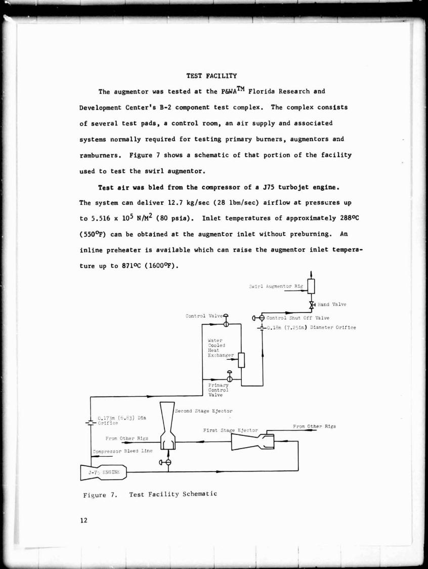
NASA CR-134639 FR-6@4 FINAL REPORT EFFECT OF SWIRLING FLOW ON AUGMENTOR PERFORMANCE BY T. R. Clements PRATT & WHITNEY AIRCRAFT FLORIDA RESEARCH AND DEVELOPMENT CENTER Prepared For NATIONAL AERONAUTICS AND SPACE ADMINISTRATION NASA Lewis Contract Research Centc:r NAS3-17348 https://ntrs.nasa.gov/search.jsp?R=19750003900 2020-04-05T21:20:07+00:00Z
Transcript
NASA CR-134639 FR-6@4
FINAL REPORT
EFFECT OF SWIRLING FLOW ON
AUGMENTOR PERFORMANCE
B Y T. R. Clements
PRATT & WHITNEY AIRCRAFT
FLORIDA RESEARCH A N D DEVELOPMENT CENTER
Prepared For
N A T I O N A L A E R O N A U T I C S A N D SPACE A D M I N I S T R A T I O N
P r a t t & Whitney Ai rc ra f t Division of United Ai rc ra f t Corporation Flor ida Research and Development Center West Palm Beach, Flor ida 33402
s
2. Sponsoring Agency Name and Address
National Aeronautics and Space Administrat ion Washington, D. C . 20546
P-o jec t Manager; A. J . Juhasz, A i r Breathing Engines Divis ion, NASA-Lewis Research Center, Clevelacd, Ohio
5. Report Date
November 1974 6. Performing Organization Code
11. Contract or Grant No.
NAS3-17348
13. Type of Report and Period Covered Contractor June 1973-June 1974
14. Sponsoring Agency Code
- -- - --
6. Abstract
A t e s t program was conducted with an augmentor which employed swi r l ing flow as a means of promoting rapid flame propagation. The program evaluated t h e e f f e c t of augmentor length , swirl i n t e n s i t y , f u e l zoning and Mach number on augmentor performance. Combustion e f f i c i e n c i e s near 100% were demonstrated over most of t h e ope ra t ing range which extended from an equivalence r a t i o of 0.2 t o ovcr 1.9. The t e s t s were conducted a t an i n l e t temperature of 649 '~ ( 1 2 0 0 ~ ~ ) and a t a pressure of 2 atmospheres. The augmentor t o t a l pressure los ses were t y p i c a l of current " s t a t e - of - the-ar t" augmentors.
7. Key Words (Suggested by Autnorls) 1
Augmentor, Swir l , Swirl i.ng Flow, Afterburner, Turboje t , Exhaust Emissions, Combustion Eff ic iency, Pressure Loss, Exhaust A i r Angle
18. D~stribution Statement
Unclass i f ied - Unlimited
I 9 Secur~ty Class~f (of thus report)
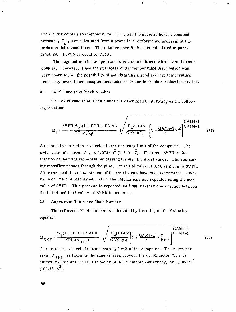
Unclassif ied
20. Seeur~ty Classif. (of this page)
Unclass i f ied
21. No. of Pages
88
22. Price'
The research described herein was conducted by the Pratt 6 Whitney
Aircraft Division of United Aircraft Corporation under Cnntract NAS3-17348
with Mr. Albert J. Juhasz of the Air-Breathing Engines, Division NASA-
Lewis Research Center as Project Manager.
The period of performance for the contract was June, 1973 through
A t e s t program has been conducted wi th a n exper imenta l augmentor
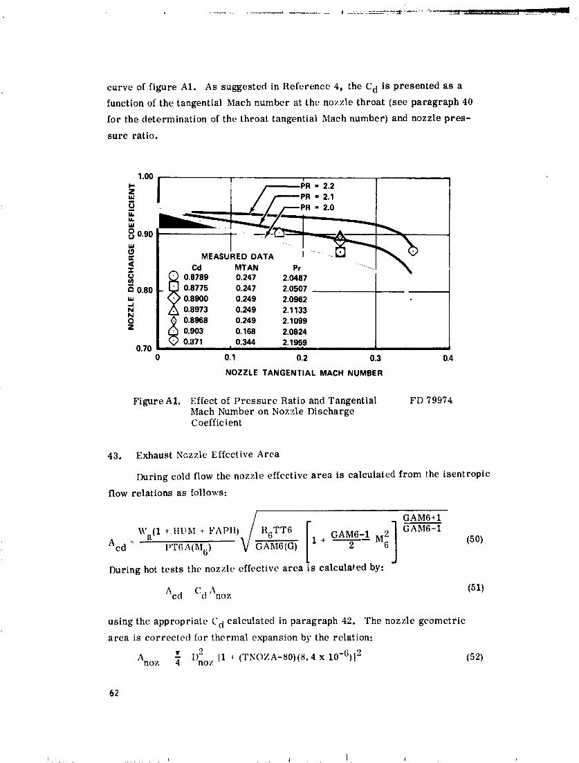
t h a t employed s w i r l i n g flow t o p r r a o t e r ap id flame propagation. The
augmentor combustion zone was 0.381 meters (15 inches) ~n diameter.
Three combustor cases were used g iv ing combustor length-to-diameter
r a t i o s (LIDS) of 0.914, 1,414 and 2.414. The s w i r l i n g flow was c r e a t e d
wi th swirl vanes loca ted upstream of t h e f u e l i n j e c t i o n sp rayr ings .
Three swirl vane ang les were t e s t e d wi th nominal values of 0.44, 0.61
and 0.79 rad ians (25 , 35 and 45 degrees) .
Two f ixed a r e a , convergent exhaust nozzles were ased t o s tudy t h e
e f f e c t of Mach number on combastion e f f i c i e n c y . The smal le r nozzle had
s nominal t h r o a t diameter of 0.219 meters (8.62 inches ) . The l a r g e r
nozzle had a nominal t h r o a t diameter of 0.272 meters (10.69 inches) .
The t e s t s were conducted a t cond i t ions s imula t ing those of an
augmented t u r b o j e t engine. The augmentor i n l e t temperature was 6 4 9 ' ~
(1200°F) and the combustion zone pressure was 2 atmospheres.
The demonstrated combustion e f f i c i e n c y was high. Wjch t h e 1.414
L/D combustion zone and t h e 0.61 radian (35 degree) swirl vanes t h e
combustion e f f i c i e n c y was near 100% a t an augmentor equivalence r a t i o
of 1.0.
The combustion e f f i c i e n c y was shown t o be s t r o n g l y dependent on
t h e zoning of the f u e l flow between the th ree r i g f u e l i n j e c t i o z zprav-
r ings .
The bes t r e s u l t s were obtained by g radua l ly i n j e c t i n g t h e f u e l
from the o u t e r r i n g t o t h e inner r i n g a s t h e f d e l loading was increased.
The augmentor i n l e t Mach number was shown t o have no e f f e c t on the
measured combustion r f f i c i e n c y . The only except ion t o t h i s was when
f u e l was zoned between t h e o u t e r and inner sp ray ings . With t h a t f u e l
zoning combination t h e combustion e f f i c i e n c y was h i g h e s t with t h e
h igher Mach numbers.
The augmentor ccZd t o t a l p ressure l o s s was shown t o be equa l t o
t h a t of c u r r e n t h igh performance convent ional systems. A t a n i n l e t Mech
number of 0.25 t h e t o t a l p ressure l o s s , expressed a s a drag c o e f f i c i e n t
(p ressure l o s s / i n l e t dynamic head) was 0.900.
To i n i t i a t e and mainta in combustion, a s w i r l i n g flow augmentor has
an annular p i l o t burner surrounding the o u t e r wa l l of t h e combustion
zone. As long a s the p i l o t is opera t ing t h e mainstream flow can be
ign i t ed . Therefore , t h e l ean blow-out was def ined a s t h e lean f lauanabi l i ty
l i m i t of t h e p i l o t . This was determined t o occur a t an augmentor f u e l -
a i r r a t i o of 0.0007 a t t h e 6 4 9 ' ~ ( 1 2 0 0 ~ ~ ) i n l e t temperature.
During t h e course of t h e program combust ion i n s t a b i l i t i e s (rumble)
i n t h e 90 t o 100 Hz range occurred. However, by proper zoning of t h e
f u e l flow between the t h r e e f u e l i n j e c t i o n zones rumble was prevented,
pe rmi t t ing augmentor opera t ion over t h e e n t i r e f u e l flow range.
INTRODUCTION
Conven t iona l augmentors a r e l a r g e d e v i c e s . T h i s i s p r i m a r i l y due
t o t h e f lame s t a b i l i z a t i o n and p ropaga t ion mechanisms employed. The
flame s t a b i l i z i n g mechanisms c o n s i s t of "vee g u t t e r s " , " r a d i a l vee
< u t t e r s t ' o r combina t ions of t h e s e . These d e v i c e s o p e r a t e by c r e a t i n g
a q u i e s c e n t r e g i o n i n which combust ion can be ma in t a ined . The flame
t h e n p ropaga te s through t h e unburned f u e l - a i r mix tu re by t u r b u l e n t eddy
d i f f u s i o n . It i s t h i s p roces s t h a t r e s u l t s i n t h e r a t h e r l a r g e s i z e of
c u r r e n t augmentors . As t h e f lame p r o g r e s s e s through t h e unburned f u e l -
a i r m ix tu re t h e r e s u l t i n g flame s p r e a d i n g a n g l e i s approximate ly 0.052
t o 0.070 r a d i a n s ( 3 t o 4 d e g r e e s j f o r each f lame h o l d i n g dev ice . Conse-
q u e n t l y , a l a r g e number of f lame h o l d e r s and c o n s i d e r a b l e l e n g t h a r e needed
t o s p r e a d t h e flame comple te ly a c r o s s t h e d u c t .
However, a s t h e fiumber of flame h o l d e r s is i n c r e a s e d , t h e augmentor
t o t a l p r e s s u r e l o s s e s go up. Consequent ly , t o m a i n t a i n r ea sonab le p r e s s u r e
l o s s e s and combust ion e f f i c i e n c i e s a compromise i s made between t h e nuvket
of f l ameho lde r s and augmentor l e n g t h . T h i s p rocsas u s u a l l y r e s u l t s i n
f a i r l y l ong combust i on chambers.
T h i s method of flame s t a b i l i z a t i o n and p ropaga t ion h a s s e v e r a l
drawbacks. F i r s t , t h e s t r u c t u r e r e q u i r e d t o mount t h e f lameholders a s
w e l l a s t h e f lameholders t h e m ~ ~ ~ l v e s can be compl ica ted and prone t o f a i l u r e .
Second, t h e c o o l i n g of t h i s s t r u c t u r e i s agg rava t ed due t o t h e h igh
t empera tu re of t h e e n t e r i n g a i r . T h i r d , a s i n d i c a t e d above, t h e combustion
e f f i c i e n c y and a l s o t h e t o t a l p r e s s u r e l o s s vary d i r e c t l y w i t h t h e number
o f f l ameho lde r s . It i s t h i s t r a d e - o f f between combustion e f f i c i e n c y and
p r e s s u r e l o s s t h a t r e s u l t s i n t h e 80 t o 90 pe rcen t e f f i c i e n c i e s of
c u r r e n t augmentors . F a u r t h , t h e combust ion e f f i c i e n c y i s dependent on
t h e i n l e t Mach number.
The s w i r l i n g f low augmentor e l i m i n a t e s o r minimizes t h e above
problems. It o p e r a t e s on t h e p r i n c i p l e t h a t ho t burned g a s e s w i l l " r i s e "
and t h e c o l d e r unburned g a s e s w i l l s i n k due t o t h e c e n t r i p e t a l a c c e l e r a -
t ion c r e a t e d by a s t r o n g l y s w i r l i n g f lowf i e l d . The b e n e f i c i a l e f f e c t s
o f s w i r l i n g flow were r e p o r t e d on ove r 20 y e a r s ago by I. R . Schwartz
( r e f . 1 ) who showed t h a t combustion i n a s w i r l i n g f low is more s t a b l e
and has l e s s smoke than non- swi r l i ng combustion. G. 3. Lewis ( r e f 2 )
ha s shown t h a t flame p ropaga t ion v e l o c i t y i n a s t r o n g l y s w i r l i n g f low
f i e l d ( c e n t r i p e t a l a c c e l r a t i o n s 2000 t o 4000 t imes t h e s t a n d a r d a c c e l e r a -
t i o n due t o g r a v i t y ) i s c o n t r o l l e d comple te ly by t h e bouyant f o r c e s
a c t i n g on t h e ho t gases and may be a s h igh a s f i v e t imes normal t u r b u l e n t
f lame p ropaga t ion v e l o c i t y . The bouyancy of t h e h o t g a s e s i s p r o p o r t i o i ~ a l
t o t h e l o c a l c e n t r i p e t a l a c c e l e r a t i o n wh i l e t h e d r a g f o r c e i s p r o p o r t i o n a l
t o t h e squa re of t h e ho t gas bubble v e l o c i t y . By e q u a t i n g t h e bouyant and
d r a g f o r c e s it can be shown Lhat t h e ho t gas bubble v e l o c i t y o r flame
speed is g iven by:
- V = C \, g,
where "V" i s t h e f lamespeed and "gs" is t h e l o c a l c e n t r i p e t a l a c c e l e r a t i o n .
The va lue of t h e c o n s t a n t C has been de termined t o be app rox ima te ly 1.25
a s r e p o r t e d i n r e f e r e n c e 2 . With p r o p e r l y des igned swirl vanes , c e n t r i -
p e t a l a c c e l e r a t i o n s of 2400 "g's" c a n be gene ra t ed i n a .914 meter ( 3
f o o t ) d i ame te r duc t a t a p e n a l t y of 2 t o 3 pe rcen t i n t o t a l p r e s s u r e .
With t h i s l e v e l of a c c e l e r a t i o n , f lamespeeds of 18.6 me te r s p e r second
( 6 1 f e e t p e r second) a r c p o s s i b l e .
Because t h e flame s p r e a d s toward t h e c e n t e r of r o t a t i o n , combustion
i s i n i t i a t e d and main ta ined by a n a n n u l a r p i l o t bu rne r s ~ ~ r r o u n d i n g t h e
augmentor . As wi th c o n ~ e n t i o n a l augmentors , t h e r e a r e s e v e r a l f u e l
i n j e c t i o n zones t o d i s p e r s e t h e f u c ? uni formly over t h e d u c t . T h i s
concept o f f e r s s e v e r a l p o t e n t i a l advan tages :
1. Improved combustion e f f i c i e n c y due t o t h e ve ry h i g h flame speeds
2 . S h o r t e r l e n g t h
3 . No e L f e r t on combust ion e f f i c i e n c y due t o i n l e t Mach number.
As t h e Mach number i n c r c a s e s t h e flame speed i n c r e a s e s i n t h e
same p r o p o r t i o n .
4. No need f o r "vee g u t t d r " t y p e f l ameho lde r s .
5. Lower p r e s s u r e drop . A l so , i f an i n c r e a s e i n complexi ty can be
t o l e r a t e d , t h e swirl vane a n g l e can be made a d j u s t a b l e . T h i s
would a l l ow c o n t r o l of t h e s w i r l intensity s o t h a t o n l y t h a t
l e v e l r e q u i r e d f o r 100 pe rcen t combustion is s e t . T h i s makes
p o s s i b l e c o n s i d e r a b l e r educ t i ons i n t o t a l p r e s s u r e l o s s d u r i n g
non-augmented and low power augmented o p e r a t i o n s . During c r u i s e
t h e augmentor i s normal ly o f f . T h e r e f o r e , w i th a d j u s t a b l e
swirl vanes t h a t c a n be opened f u l l y s o t h a t no swirl i s
imparted t o t h e f low s i g n i f i c a n t r e d u c t i o n s i n eng ine t o t a l
p r e s s u r e l o s s e s can be made. I f a p p l i e d t o c u r r e n t h igh
performance, augmented eng ines t h i s cou ld r e s u l t i n a one t o
two pe rcen t d e c r e a s e i n c r u i s e t h r u s t s p e c i f i c f u e l consumption.
6 . Reduced exhaus t emis s ions . Andre' Mest r e ( r e f . 3) showed t h a t
exhaus t emis s ions were lower wi th s w i r l i n g f low t h a n w i t h non-
s w i r l i n g flow combust ion.
The purpose o f t h i s program was t o demonst ra te t h e c a p a b i l i t y of
t h e s w i r l flow auginentor concept t u produce h i g h combust ion e f f i c i e n c i e s .
The t e s t s were conducted a t c o n d i t i o n s s i m u l a t i n g t h o s e of a n augmented
t u r b o j e t engine . The augmentor i n l e t t empera tu re was normally 64g0c
(1200'~) and t h e t o t a l p r e s s u r e was 2 atmospheres.
The program was des igned t o gene ra t e pa rame t r i c da t a on t h e e f f e c t s
of swirl i n t e n s i t y , combustion zone l e n g t h , f u e l zoning and Mach number
on combustion e f f i c i e n c y a s w e l l a s l o c a i e p o t e n t i a l problem a r e a s . Four
f u e l s p r a y r i n g c o n f i g u r a t i o n s were t e s t e d i n developing t h e f i n a l con£ ig -
u r a t i o n . Data a r e p re sen ted f o r t h e f i n a l c o n f i g u r a t i o n on ly . These
s p r a y r i n g s were t e s t e d w i t h a l l t h r e e of t h e o r i g i n a l l y planned swirl
ang le g e n e r a t o r s but w i t h only t h e two s h o r t e r of t h e o r i g i n a l l y planned
combustor i e n g t h s (LID'S of 0.914, 1.414 and 2.414).
AUGMENTOR DESIGN
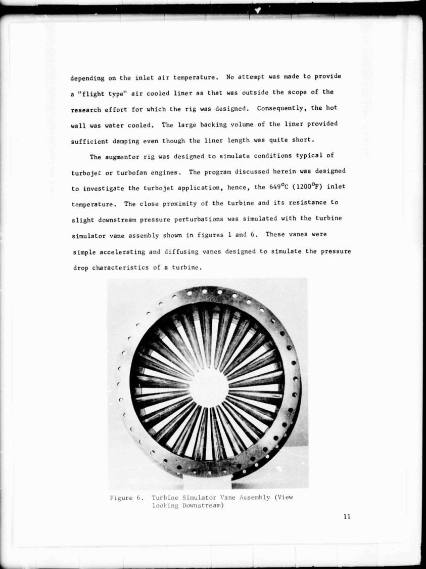
The exper imenta l augmentor used i n t h i s program is shown i n f i g u r e
1 I n f i g u r e 2 t h e r i g i s shown i n o p e r a t i o n a t an equ iva lence r a t i o of
1.0. The 0.381 meter (15 inch) d iameter of t h e augmentor combustion
s e c f i o a was s e l e c t e d s o a s t o be compat ib le w i t h t h e t e s t f a c i l i t y a i r -
flow a t d p re s su re c a p a b i l i t i e s .
To gene ra t e t h e pa rame t r i c da t a r e q u i r - d , s e v e r a l s e t s of r i g hard-
ware were f a b r i c a t e d . Among t h e s e were t h r e e swirl vane a s sembl i e s w i t h
nominal t u r n i n g a n g l e s of 0.44, 0.61 and "79 . radians (23 , 35 and 45
d e g r e e s ) . The swirl vanes c r e a t e t h e s t r o n g l y s w i r l i n g flow e s s e n t i a l
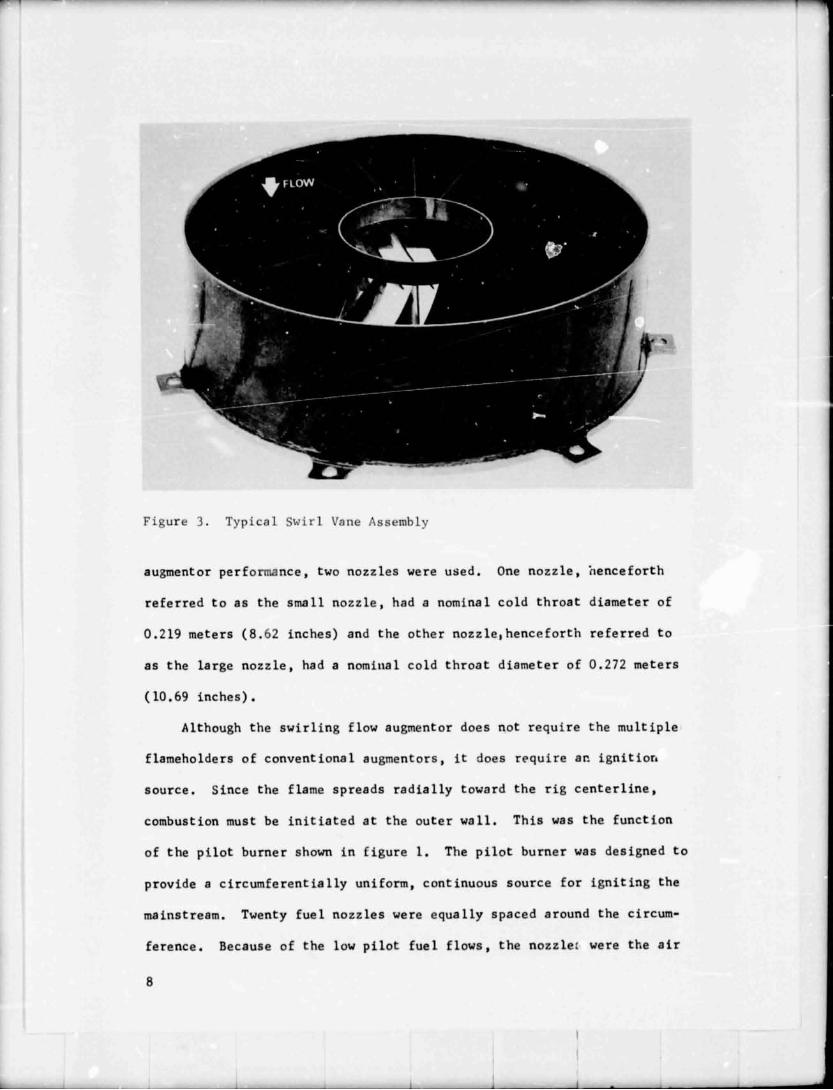
t o t h e concept . A t y p i c a l s w i r l vane assembly i s shown i n f i g u r e 3. A s
shown, t h e vanes were s imple curved sheec meta l vanes t o minimize c o s t .
Three water cooled combustion chambers were a v a i l a b l e t o provide
combustion zone l eng th - to -d i ame te r r a t i o s of 0.914, 1.414 and 2.414.
Tz c i w p l i f y t h e des ign and reduce t h e c o s t of t h e r i g , a f i x e d a r e a
convergent exhaus t nozz le was used . A S w i t h t h e combustion chambers, t h e
w a l l s were water cooled . I n o r d e r t o s t ~ d y t h e e f f e c t of Mach number on
b l a s t t ype i n which f u e l a t o m i z a t i o n is accomplished wi th h igh v e l o c i t y
airft .ows. T h i s t ype nozz l e w i t h i t s l a r g e i nLe rna l f u e l passages is
l e s s s e n s i t i v e t o contaminated f u e l s . To s t a b i l i z e combast ion i n t h e
p i l o t zone, each f u e l nozz l e was equipped w i t h a n a i r s w i r l e r . A l l of t h e
p i l o t zone a i r flow e n t e r e d through t h e f u e l n o z z l e s and s w i r l e r s . T o t a l
p i l o t a i r f l o w was approximate ly 4 .5 pe rcen t of t h e t o t a l augmentor f low.
To d i s t r i b u t e t h e f u e l un i formly a c r n s s t h e d u c t , t h r e e c o n c e n t r i c
f u e l zones were provided i n t h e augmentor combustion chamber, The
s p r a y r i n g s f o r each zone were l o c a t e d a t t h e c e n t e r of e q u a l £ l o r a r e a s
s o t h a t each r i n g f ed one t h i r d of t h e mainstream flow. Each s p r a y r i n g
i n j e c t e d f u e l r a d i a l l y both nr~tward and inward t o p rov ide more uniform
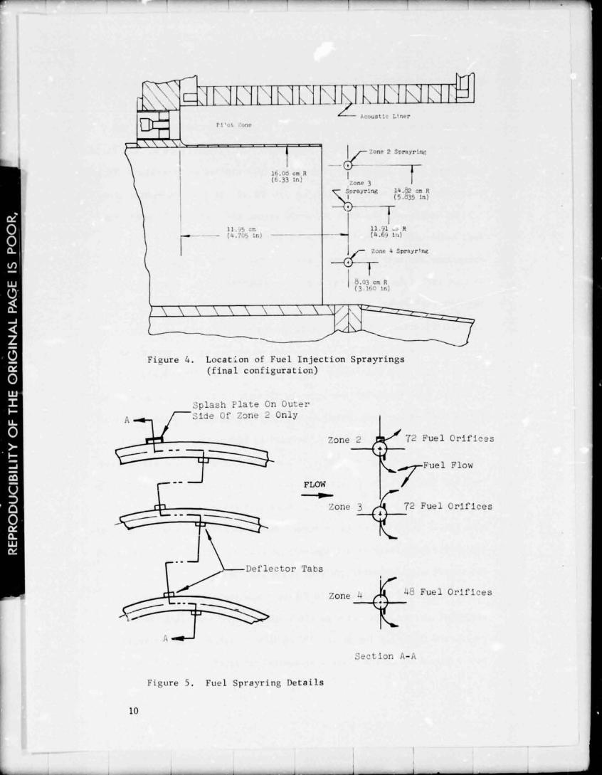
f u e l d i s t r i b u t i o n . The l o c a t i o n of t h e s p r a y r i n g s i s shown i n f i g u r e 4 .
I n t h e d i s c u s s i o n s t h a t fo l l ow t h e o u t e r s p r a y r l q is r e f ~ r r e d t o a s
Zone 2. Zone 3 is t h e c e n t e r r i n g and Zone 4 is t h e i n n e r s p r a y r i n g .
F u e l from each s p r a y r i n g was i n j e c t e d through a number of c i r c m . £ e r e n ~ i a l l y
spaced d r i l l e d o r i f i c e s . Fue l a t o m i z a t i o n was enhanccd by t h e a d d i t i o n
of d e f l e c t o r t a b s immediately downstream of each o r i f i c e a s shown i n
f i g u r e 5. T h i s d e s i g n coupled w i t h t h e 645'0C (12000F) i n l e t a i r tempera-
t u r e was cons ide red t o p:uvide adequaie i u e l a t o m i z a t i o n and v a p o r i z a t i o n
w i t h considerable savin,:s i n c o s t . Four f u e l s p r a y r i n g c o n f i g u r a t i o n s
were t e s t e d i n an e f f o r t t o i n c r e a s e combustion e f f i c i e n c y wh i l e ma in t a in -
ing s t a b l e combust ion a t a l l equ iva l ence r a t i o s . The f i n a l con£ i g u r a t i on
was t e s t e d w i th combustor LID'S of 0.914 and 1.414.
The a c o u s t i c l i n e r shown i n f i g u r e 1 was i n s t a l l e d because t e s t s
conducted p r i o r t o t h e s t a r t of t h e program showed t h e r l g t o have
combustion i n s t a b i l i t i e s i n t h e 500 t o 1000 Hz range. The i n s t a b i l i t i e s
were a n z ~ y z e d t o be t h e f i r s t l o n g i t u d i n a l o r f i r s t t ang r .n t i a1 mode
Serving the t e s t s t a n d is a 100-channel d i g i t a l recorder capable of
recording a t a maximum sampling r a t e of 6666 s a r p l e s per second. Data a r e
recorded on magnetic tape which is d i r e c t l y compatible wi th a high-speed
d i g i t a l computer. Also provided a r e 40 channels of s t r i p c h a r t r ecorders
f o r real-t ime t e s t monitoring and a 36-channel osc i l lograph f o r h igher
frequency da ta recording.
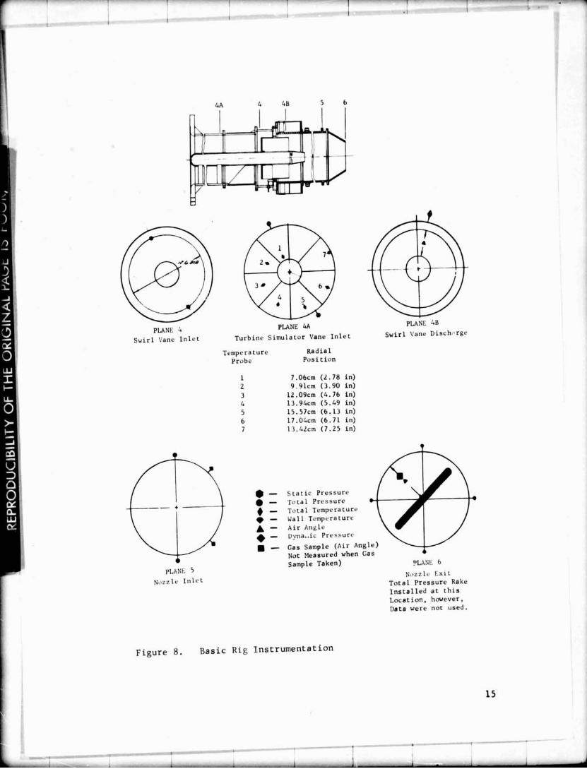
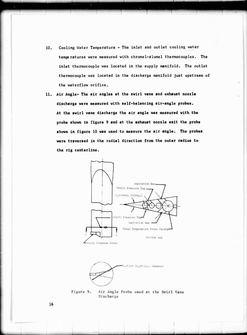
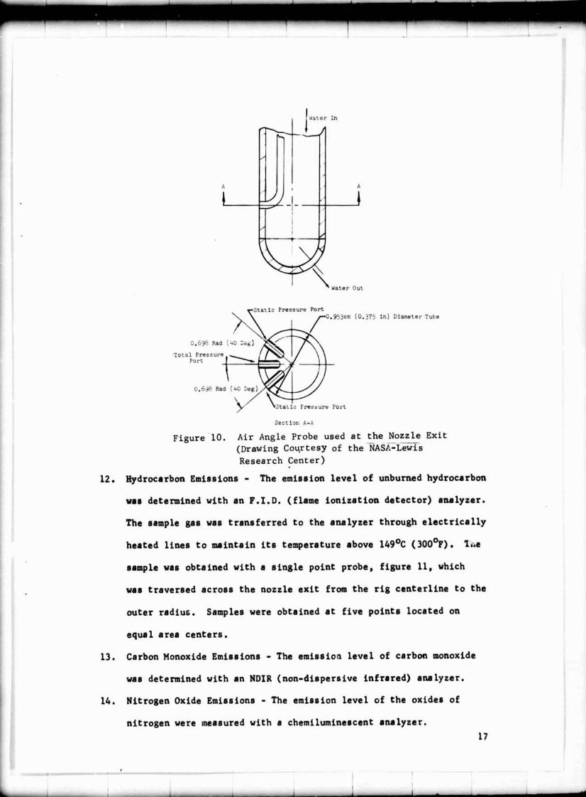
INSTRUMENTATION
The t e s t r i g was instrumented a s shown i n f i g u r e 8 t o provide da ta
on r i g a i r f low, f u e l flow, augmentor i n l e t t o t a l p ressure , combustion
zone s t a t i c pressure , exhaust nozzle wa l l temperature, a i r angle a t t h e
swirl vane and nozzle o u t l e t s , and t h e emission l e v e l s of unburned hydro-
carbon, carbon monoxide and t h e oxides o f n i t rogen . The r i g c o o l i q
water f lowrate and i n l e t and o u t l e t temperature were measured a s we l l .
These da ta were used t o c o r r e c t t h e combustion e f f i c i e n c y f o r h e a t
r e j e c t e d t o t h e cool ing water. The ins t rumentat ion used is b r i e f l y
described i n the following paragraphs.
Augmentor Airflow - The a i r f l o w t o the r i g was measured wi th a
0.184 meter (7.25 inch) diameter sharp-edged o r i f i c e . The o r i f i c e
upst ream and downstream pressures were measured wi th f lange s t a t i c
pressure t aps . The a i r temperature was measured wi th two chromel-
alumel thermocouples located downstream of t h e o r i f i ce . I n case
t h e ins t rumentat ion on t h i s o r i f i c e should f a i l a back-up 0.173
meter (6.83 inch) diameter o r i f i c e was a v a i l a b l e t o measure r i g
a i r f low. The ins t rumentat ion on t h a t o r i f i c e was s i m i l a r t o t h a t
cf the primary o r i f i c e .
Augmentor Fu2l Flow - The f u e l flows t o t h e p rehea te r , p i l o t and
zones 2 , 3 and 4 were measured with tu rb ine type flow meters.
Preheater I n l e t Air Temperature - This temperature was measured
with two, sh ie lded chromel-alumel thremocouples.
4 . Augmentor I n l e t T o t a l P ressure - The augmentor i n l e t t o t a l p ressure
was measured wi th two K i e l type t o t a l p ressure probes.
5. Augmentor I n l e t T o t a l Temperature - The augmentor i n l e t t o t a l tempera-
t u r e was taken a s t h e i d e a l p rehea te r o u t l e t temperature. See
Appendix A , paragraph 30. However, a s f i g u r e 8 shows, t h e augmentor
i n l e t t o t a l temperature was a l s o measured d i r e c t l y wi th seven
chromel-a lumel thermocouples.
6 . Combustion Zone S t a t i c P ressure - The s t a t i c p ressure i n t h e combustion
zone was measured wi th two wa l l t a p s loca ted imnedia te ly upstream of
t h e exhaust nozzle .
7. Exhaust Nozzle T o t a l P ressure - The t o t a l p ressure a t t h e exhaust
nozzle was normally c a l c u l a t e d by an i t e r a t i v e procedure us ing t h e
nozzle i n l e t and t h r o a t geometric a r e a s , t h e augmentor mass flow
and t h e combustion zone s t a t i c p ressure a t t h e nozzle i n l e t . See
Appendix A , paragraph 38. For most of t h e t e s t s , however, t h i s
p r ,adure was supplemented wi th a d i r e c t measurement of t o t a l
pressure wi th a mul t i -point r ake , s e e f i g u r e 8.
8. Exhaust Nozzle Wall Temperatcre - The w a l l temperature of t h e exhaust
nozzle was measured wi th four chromel-alumel thermocouples loca ted
a t t h e nozzle t h r o a t and equa l ly spaced around t h e circumference.
These data were used t o c o r r e c t the nozzle t h r o a t diameter f o r
thermal expansion.
9 . Cooling Water Flowrate - The cool ing water f lowra te t o t h e r i g was
measured wi th a 0.031 meter (l.225 inch) diameter sharp edged o r i f i c e
located i n t h e d ischarge manifold. The o r i f i c e was equipped wi th
f lange s t a t i c p ressure t aps .
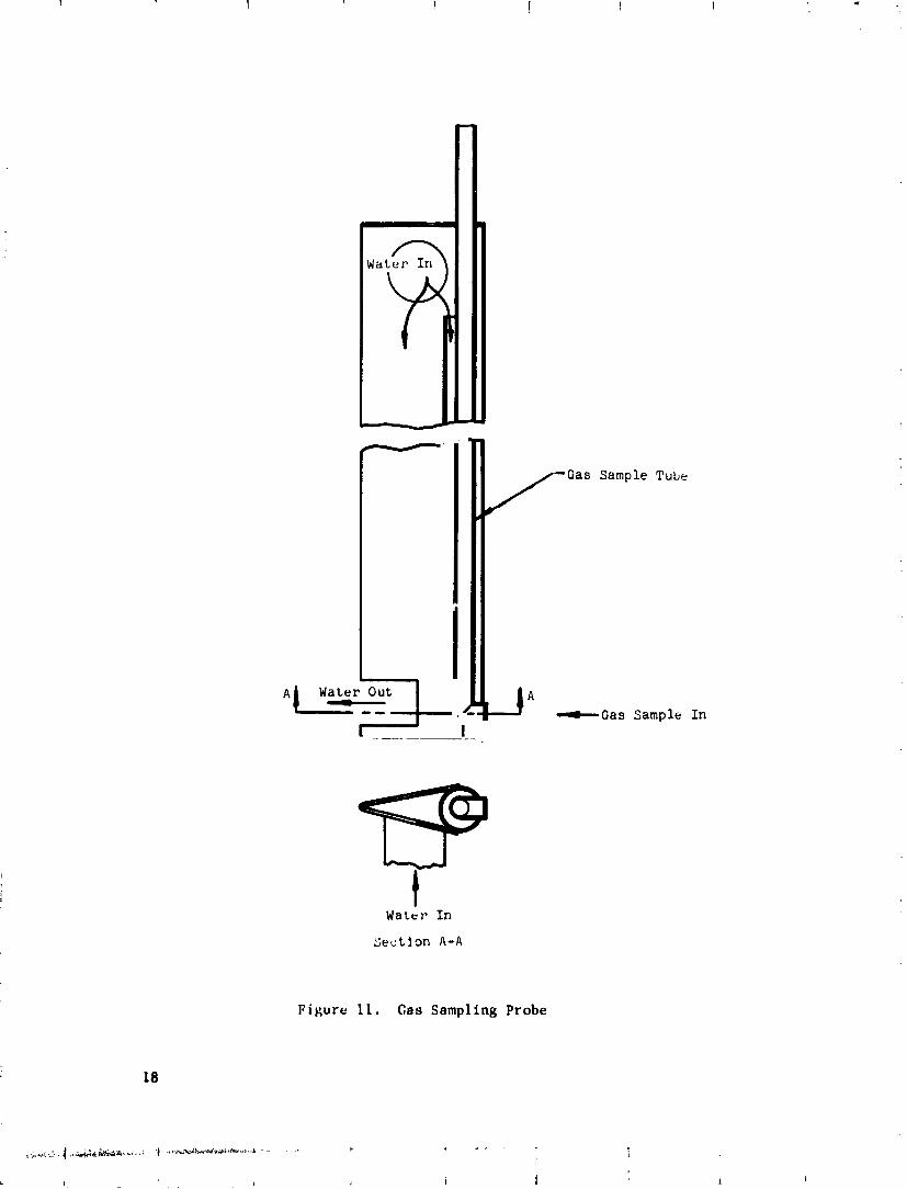
/ -Gas Sample Tube
Section A - A
Figure 11. Gas Sampling Probe
+Gas Sample In
EXPERIMENTAL PROCEDUKE
The s w i r l augmentor was t e s t e d a t a near cons tan t pressure of 2
atmospheres over t h e f u l l range of equivalence r a t i o s inves t iga ted . With
the small nozzle i . ~ s t a l l e d , t h e augmentor was brought on l i n e by f i r s t
increas ing the a i r f l o w and p rehea te r f u e l flow u n t i l t h e exhaust nozzle
was choked and an i n l e t temperature of 6 4 9 ' ~ ( 1 2 0 0 9 ) was s e t . The p i l o t
burner was thcn i g n i t e d a t e l o c a l equivalence r a t i o of 1.0 us ing a n auto-
motive type spark plug. The p i l o t was maintained a t a n equivalence r a t i o
of approximately 1.0 dur ing t h e remainder of t h e test. The var ious r i g
f u e l zones were brought oc l i n e by simply s e t t i n g t h e f u e l flow des i red .
I g n i t i o n was accomplished with t h e p i l o t burner. Minimum f u e l flow t o
each zone was approximately 90.7 ~ g / H r (200 pph). This was required t o
s t a y above t h e lower opera t ing l i m i t of t h e t u r b i n e type flow meters.
With t h e l a rge nozzle i n s t a l l e d the s t a r t up procedures had t o be
modified. A t t h e 64g0c ( 1 2 0 0 9 ) i n l e t temperature cond i t ion t h e a i r f l o w
required t o choke t h e l a r g e nozzle was g r e a t e r t h a n t h e f a c i l i t y capa-
b i l i t y . Therefore, an i n i t i a l a i r £ low of approximately 9.0 Kg/sec
(20 lbmlsec) was s e t . The p i l o t burner was i g n i t e d a s before and a n
equivalence r a t i o g r e a t e r than 0.2 was s e t on one of t h e augmentor f u e l
zonea. With t h e increased nozzle o u t l e t temperature t h e nozzle could be
choked wi thin t h e a i r f l o w capac i ty of t h e f a c i l i t y .
Since t h e d e s i r e d t e s t cond i t ion was 2 atmospheres i n l e t pressure
and 64g0c ( 1 2 0 0 ~ ~ ) i n l e t temperature the a i r f l o w and p rehea te r f u e l flow
had t o be ad jus ted whenever the augmentor equivalence r a t i o was a l t e r e d .
This r e s u l t s from using a f ixed a rea exhaust nozzle. Figure 12 shows
the re la tic^ between the swirl vane i n l e t Mach Number and t h e augmentor
equivalence r a t i o wi th both t h e small and large nozzles a t t h e 2 atmos-
phere t e s t cond i t ion assuming 100% combust ion e f f i c i e n c y .
0.272m (10.59) Diameter Nozzle
-0.219m (? ' .62) Diameter Nozzle
AUGMENTOR E Q U I V A L E N C E R A T I O
Figure 12. Var ia t ion of S w i r l Vane I n l e t Mach Number wi th Augmentor Equivalence Ra t io
A l l of t h e data wi th t h e except ion of t h e gas sampling da ta were
recorded us ing a high speed d i g i t a l recording system. Between d e s i r e d
t e s t pn in t s t h e recording system was operated a t a recording speed of
1 scan l sec which means t h a t a l l of t h e d a t a channels were recorded one
time each second. When a t e s t point was s e t , however, t h e recording
speed was increased t o 10 scans l sec and data were recorded over a f i v e
second i n t e r v a l . These 50 readings were subsequently averaged t o provide
a good value f o r each data channel.
I n t h e program t h e combustion e f f i c i e n c y was determined by gas
sampling and by t h e "choked nozzle method". With t h e "choked nozzle
method," i f t h e mass flow, t o t a l p ressure , and nozzle geometric a rea and
discharge c o e f f i c i e n t a r e known t h e exhaust temperature and hence combus-
2 0
t ion e f f i c iency can be determined. The nozzle d i scharge c o e f f i c i e n t
was determined by choking the nozzle during cold f l o v s o t h a ~ an
isothermal temperature f i e l d e x i s t e d a t the nozzle . The mass flow and
nozzle t o t a l p ressure were then measured and t h e nozzle d ischarge c o e f f i -
c i e n t determined us ing the e f f e c t i v e area determined f rom the measured
values of mass flow, t o t a l pressure and temperature and the known
goemetric a r e a . Th i s was done f o r t h e smal l nozzle us ing a l l t h r e e
s w i r l vane assembl ies and a l s o without any swirl. With t h e l a rge nozzle ,
however, t h e i n l e t a i r temperature had t o be r a i s e d t o over 9 2 . ' ~ (1700'~)
with t h e p rehea te r i n o rde r t o choke the nozzle wi th t h e a v a i l a b l e
a i r f l o w r a t e . Th i s presented a high r i s k of damaging uncooled por t ions
of the r i g immersed on t h e gas stream. Consequently only one c a l i b r a t i o n
point us ing t h e 0.61 rad (35 deg) s w i r l vanes was obtained.
The gas sampling equipment was c a l i b r a t e d i n accordance with the
Soc ie ty of Automotive Engineers S p e c i f i c a t i o n ARP 1256.
CALCULATIONS
The bas ic performance c a l c u l a t i o n s a r e presented i n the following
paragraphs. For a more complete d e s c r i p t i o n of t h e performance calcu-
l a r ion procedure s e e Appendix A .
Combust ion Ef f i c i ency - The augmentor combust ion e f f i c i e n c y is normally
given by:
EFEMB
where
= 100 [ TT6 - TT4A + 3600 Q l o s s 7 TT6IDEAL-TT4A 4 . 2 7 3 X 1 0 Wn I
EFFTiB augmentor combustion e f f i c i e n c y , %
TT6 - a c t u a l o u t l e t t o t a l temperature , OC (OF)
TT6IDEAL = i d e a l . u t l e t t o t a l temperature , OC (OF)
TT4A = i n l e t t o t a l tempernture, OC (OF)
Qloss = hea t r e j e c t e d t o combustion chamber jacket coo l ing
water , Jou les / sec ( ~ T U / s e c )
W F T = augmentor f u e l flow, ~ g / ~ r (pph)
The hea t ing value of the JP-5 keros ine f u e l was t aken a s 4.273 x 10 7
Joules /kg ( 18370 ~TU/lbm).
For a p o r t i o n of t h e t e s t i n g t h i s method of determining cwm~,usticn
e f f i c i e n c y was supplemented by a second method based on a n a l y s i s of :he
exhaust products. By determining t h e amount of unburned hydrocnrhona
and carbon monoxide s t i l l p resen t i n the gases pass ing throu . ' ..? nozzle
t h e c m b u s t i o n e f f i c i e n c y can be determined from:
EFFMB HVco (CO) 4 HVf (UHCl
= 100 - 100 HVf x 103 1 where
EFFMB = augmentor combust ion e f f i c i e n c y , f
CO = emission index of carbon monoxide
UHC = emission index of unburned hydrocarbous
HVco = hea t ing value of calbon monoxide = 1.010 x l o7
Jou les /kg (4343 BT~/ lbm)
HV f = hea t ing value of t t e fue l = 4.273 x lo7 Joules /hg
( 18370 BT~/lbrn)
T o t a l Preasure Loss - The augmentor t o t a l p r e s r u r e l o s s is given by: r -
DPAUG
where
DPAUG
PT4A
PT6A
- augmentor t o t a l p ressure l o r 8 ( p e r c e n t )
= i n l e t t o t a l pressure , ~ / r n ~ ( p a i r )
- o u t l e t t o t a l pressure , ~h~ (psi.)
S w i r l Vane Mach Number - The rwi r l vane Mach Number is the Mach N d t r
of t he flow a s it en te r r the rw i r l vanes. It is given by: - {We) (1 + HUH + PAPH) SVFR *
PT4A ( A 4 ) J
where
i44 = rwirl vane i n l e t Mach Number
Wa = augmentor dry airf low , Kg/sec (lbm/rec)
SVVR = f r i c t i o n of t o t a l amas flow parsing through the
rwi r l vanes
HUH = rpec i f i c numidity
PAPH = preheater fue l -a i r r a t i o
PT4A 2 = i n l e t t o t a l pressure , N/m (p r i a )
2 A4 = swirl vane i n l e t area = 0.0729 m (113 in2)
CAM4 = gas rpec i f i c heat r a t i o
R4 = gas c o n s t a n t a t swirl vane i n l e t
G = s t a n d a r d a c c e l e r a t i o n due t o g r a v i t y
Swirl In t ens i ty - The nominal swirl in t en r i t y a t th,. p i l o t zone inner
wall expressed in terms of the standard g rav i t a t i ona l constant o r lgg'r"
is:
gs = (V4 TAN o( ) 2 / (RG)
where
gs = swi r l i n t ens i ty i n "G'r"
V4 = swir l vane i n l e t ve loc i ty ; mlrec
4 = swi r l vane turning angle , radians (degreer)
R = p i l o t zone inner wall radius , meterr ( f e e t )
G = standard acce lera t ion due t o gravi ty
RESULTS AND DISCUSS IONS
A swir l ing flow augmentor was t e s t ed a t conditions simulating those
encountered i n an augmented turboje t engine. The augmentor i n l e t tempera-
t u re and pressure were 649 '~ (1200%) and 2 atmospheres respectively.
The e f f e c t s of swirl in t ens i ty , combustion zone length, fue l zoning and
augmentor i n l e t Mach Number on augmentor performance was determined.
Table I sunrnerizes the data obtained during the program.
A. CombustionEfficiensy
I n general, the combustion e f f ic iency was high. 6y proper fue l zoning
the data show tha t combustion e f f i c i enc i e s near 100 percent could be obtained
a t equivalence r a t io s up t o 1.0.
Two methods were used t o ca lcu la te the combubtion eff ic iency. The
f i r s t was the so-called "choked nozzle method". By knowing the mass
flow, t o t a l pressure, nozzle geometric area and discharge coef f ic ien t
the t o t a l temparature of the gases passing through the nozzle and, hence,
combustion eff ic iency could be calculated.
The second method ca lcu la tes combustion e f f ic iency by determining
the amount of unburned hydrocarbons and carbon monoxide s t i l l present i n
the gases passing through the nozzle. In the discussion tha t follows
the choked nozzle data a r e f i r s t discussed. They are then compared t o
the eff ic iency data obtained by sampling the exhaust for unburned
hydrocarbons and carbon monoxide.
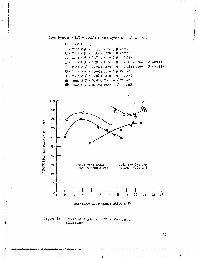
The data of f igure 13 show the e f f e c t of increasing the length-to-
diameter r a t i o from 0.914 t o 1.414. The data were obtained using the
0.219 meter (8.62 inch) diameter exhaust nozzle and the 0.61 radian (35
degree) swirl vanes with both combustor LID'S. I n general, with the
Open Symbols - L/D = 1.414; Closed Symbols - L h = 0.914
0 - Zone 2 Only
0 - Zone 2 p' = 0.175; Zone 3 $ Varied 0 - Zone 2 8' = 0.339; Zone 3 $ Varied A - zone 2 (# = 0.518; Zone 3 $ 0.134 A - zone 2 $ = 0.328; Zone 3 8' 0.335; Zone 4 p' Varied
0- Zone 2 p' =0.397; zone 3 p' 0.167; zone 4 p ' = 0.339 0 - Zone 2 $ = 0.099; zone 4 $ Varied @ - Z o n e 2 p ' = 0 . 4 6 3 ; Z o n e 3 $ 0.432
- Zone 2 8' = 0.486; zone 4 $ Varied - Zone 2 jl = 0.286; zone 4 fl 0.168
Swirl Vane Angle - 0.61 rad (35 de ) Exhaust Nozzle Dia. - 0.21% (8.62 in k
AUGMENTOR EQUIVALENCE RATIO x 10
Figure 13. Effect of Augmentor L/D on Combustion Efficiency
smaller LID the combustion e f f ic iency ;Jas reduced by 8 t o 10 percent.
Figure 13 a l s o shows, a s w i l l subseqw n t f igures , t h a t the zoning of
the fue l between the th ree r i g zones had a very la rge e f f e c t on combustion
eff ic iency. A s expected, the data show tha t it was impossible t o maintaii.
high e f f i c i enc i e s over the e n t i r e operating range with only one zone of
fue l inject ion. I n f a c t , the data show tha t the highest e f f i c i enc i e s
were obtained by gradually adding the fue l from the outside t o t h e cen te r
a s the fuel. loading was increased. Referring t o f igure 13, a s t he
augmentor equivalence r a t i o was increased beyond 0.7 the best combusi~un
ef f ic iency was obtained by in j ec t ing the fue l through zones 2 and 3.
This resul ted i n nearly a 20 percentage improvement i n combusfion e f f i c i -
ency a t the 0.7 equivalence r a t i o point when compared t o operation with
zone 2 only. However, the bes t combustion e f f ic iency (98 percent a t an
equivalence r a t i o of 1.0) was obtained with a l l three fue l zones operating.
I n shor t , :he highest combustion e f f i c i enc i e s were obtained a s t he fue l
was more evenly d i s t r i bu ted across the duct.
The problem of fue l zoning ia complicated by the superposition of
a s t rong swir l ing flow f i e l d on the mainstream flow. When the fue l is
injected, it begins t o pick up tangent ia l and a x i a l ve loc i ty components
due t o i ts in te rac t ion with the mainstream flow. The tangent ia l ve loc i ty
component c rea tes a cent r i fuga l force on the fue l mass which tends t o
dr ive it toward the outer wal l of the duct. The magnitude of t h i s force
and its e f f ec t on the notion of the fue l mass is continuously changing.
This is due, f i r s t , t o the vaporization of the fuel . A s the fue l
evaporates, the fue l densi ty decreases, thus, causing a decrease in the
magnitude of the cen t r i fuga l forces ac t ing on the fue l mass. Also, a s
the fue l mass moves toward the outer wal l , the cent r i fuga l forces ac t ing
on it decrease a s i ts r a d i a l pos i t ion increases. These e f f e c t s , along
w ! t n the normal turbulent d i f fus ion and mixing of the fue l with the a i r ,
camplicate the design and locat ion of the sprayring. The scope of t h i s
program did not include an inves t iga t ion of the dispersion of a fue l
spray i n a s t rongly swir l ing flow f i e ld . This information would be
necessary, however, t o minimize development e f f o r t f o r various applica-
t ions of a swir l ing flow augmentor.
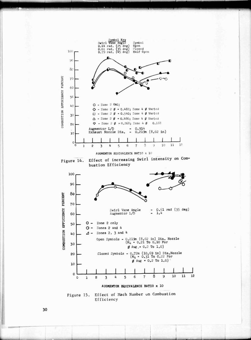
The e f f e c t of increasing swirl in t ens i ty on combustion e f f ic iency
is shown i n f igure 14. The data were obtained using the 0.219 meter
(8.62 inch) diameter nozzle and 0.44, 0.61 and 0.79 radian (25, 35, and
45 degree) swirl vanes. The augmentor LID was 0.914. The sho r t e r length
was used t o more c l ea r ly shok the e f f e c t s of increasing swirl in tens i ty .
As expected, the combustion e f f ic iency improved a s t he swirl vane angle
and, hence, swirl in t ens i ty was increased.
As previously s t s t e d , t he swirl augmentor combustion eff ic iencg
should be insens i t ive t o changes i n i n l e t Mach Number. I n f igure 15
a r e plot ted data obtained using both exhaust nozzles. The t e s t s were
run using the 0.61 radian (35 degree) s w i r l vanes. The augmentor LID was
1.4. With the small nozzle the swirl vane i n l e t Mach Number va r i e s from
0.1 t o 0.21 a s the equivalence r a t i o va r i e s from 1.0 t o 0.2. With the
la rge nozzle t he Mach Number var ies from 0.22 t o 0.31 over the same
range of equivalence r a t io s .
With zone 2 only and zones 2 , 3 and 4 there was very l i t t l e d i f f e r -
ence i n the r e su l t s . This is i n agreement with the hypothesis t h a t with
high through-put ve loc i t iea there is no e f f e c t on e f f ic iency s ince the
flame spreading r a t e increases i n the same proportion a s the through put
veloci ty .
With the zone 2 and 4 combinations there was a s ign i f i can t difference
i n e f f ic iency between the smell and large nozzles. This was obviously
the r e s u l t of the type of zoning. Why there is a d i f fe rence is unknown.
However, with the l a rge nozzle, fue l pressure drop is l a rge r and the
a i r ve loc i ty over t h e spraybars In higher. This a id s f u e l a t m i z a t i o n .
Also the 8 w i r l i n t ens i ty being la rger may have resu l ted i n a d i f f e r en t
e f f ec t ive zoning.
A s mentioned above the a n b u s t i o n e f f ic iency was a l s o deterrained by
sampling the exhaust f o r unburned hydrocarbon and carbon laonoxtde. These
data a r e p lo t ted i n f igurer 16 through 19. The data shown i n f igures 16,
17, and 18 were obtained during the same t e s t s t h a t generated the choked
nozzle data of f i g u r e 14. The data of f i g u r e 19 were taken dur ing
t h e t e s t s t h a t genera ted the l a r g e , choked nozzle data of f i g u r e 15.
Therefore t h e corresponding choked nozzle data a r e a l s o p l o t t e d f o r
comparison.
The gas sample ca lcu la ted e f f ic iency was high (90X o r grea te r ) fo r
a l l values of swirl angle t e s t ed and f o r a l l equivalence r a t io s . These
data ind ica te t h a t a l l of t he s w i r l i n t e n s i t i e s t e s t ed were s u f f i c i e n t
t o propagate the flame w e r the e n t i r e duct. This is i n disagreement
with the choked nozzle data.
No substant iated explanation is on hand t o account f o r the la rge
discrepancy i n combustion e f f ic iency val.lee a s determined by the gas
sampling and choked nozzle measurements. Extensive checks of the unburned
hydrocarbon and carbon monoxide analyzers before and a f t e r each t e s t
turned up no problems with the instruments. For most of these t e s t s ,
espec ia l ly those a t the higher equivalence r a t i o s , the sample temperatures
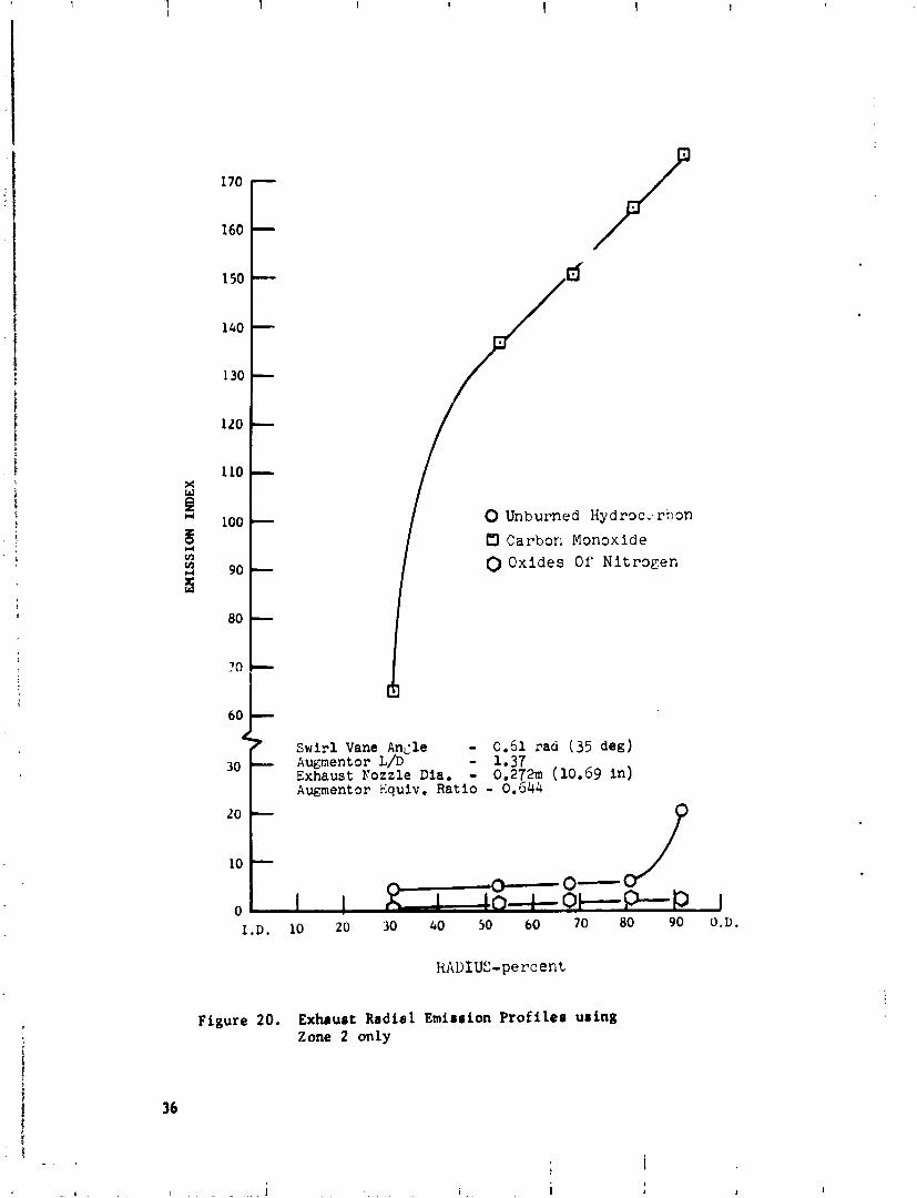
Zone 2 Only Zone 2 9 - 0.540; Zone 4 9 Varied Closed Symbols - Oas Sample Data Open Symbols - Choked Nozzle Data
Figure 20. Exhaust Radial Emission Profiles using Zone 2 only
0 Unburned H y d r w a r b m
0 Carbon Mon9xlde 0 Oxides Of N i t m g e n
Zone 2 Equ:v, Ratio - 3.430 Zone 4 Equlv. Ratlc - 0 . 1 6 ~ Augmentor Equlv. Eatlo - 0.746 Swirl Vane Angle - 0.61 rad (35 deg) Augment o r L/D - 1.?7 Exhaust Nozzle Dla, - 0.272m (10.69 i n )
Figure 21.. Exhaust Radial Emiaaion Prof i l e a us iag Zone 2 and Zone 4
0 Unburned H y d r x a r b o n
0 C a r b m Monoxide
0 O x i d e s O f N i t m g e n
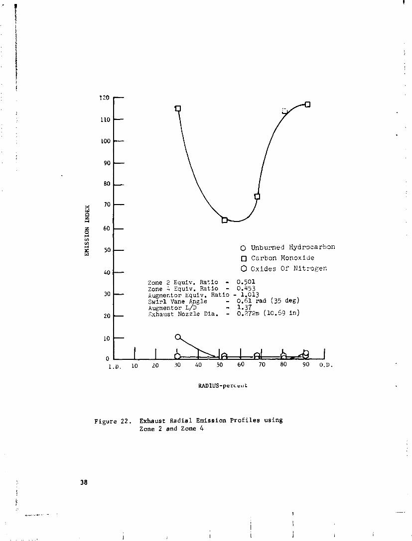
Zone 2 Equiv. Ratio - 0.501 Zone 4 Equiv. Ratio - 0.453 kugmector Equiv. Ratio - 1.013 Swir l Vane Angle - 0.61 rad (35 deg) Augment o r L/D - 1.37 Exhaust Nozzle Dia. - 0.272m (10.69 i n )
Figure 2 2 . Exhaust Radial Emission P r o f i l e s us ing Zone 2 and Zone 4
cold flow to t a l pterrure lorrer n r u l t primarily from the crut iom of
the rtrongly rwirliag flow field. Of courre,3rm in oprlntioa t h e n
are alwayr the iarrcaprble loorer due t o hart addition. Currubt expert-
ence in the d o r m of turbine8 indicate that the level of t u r a i q wed in
the program can be obtainad with lorrer on the order of 2 or 3 percent.
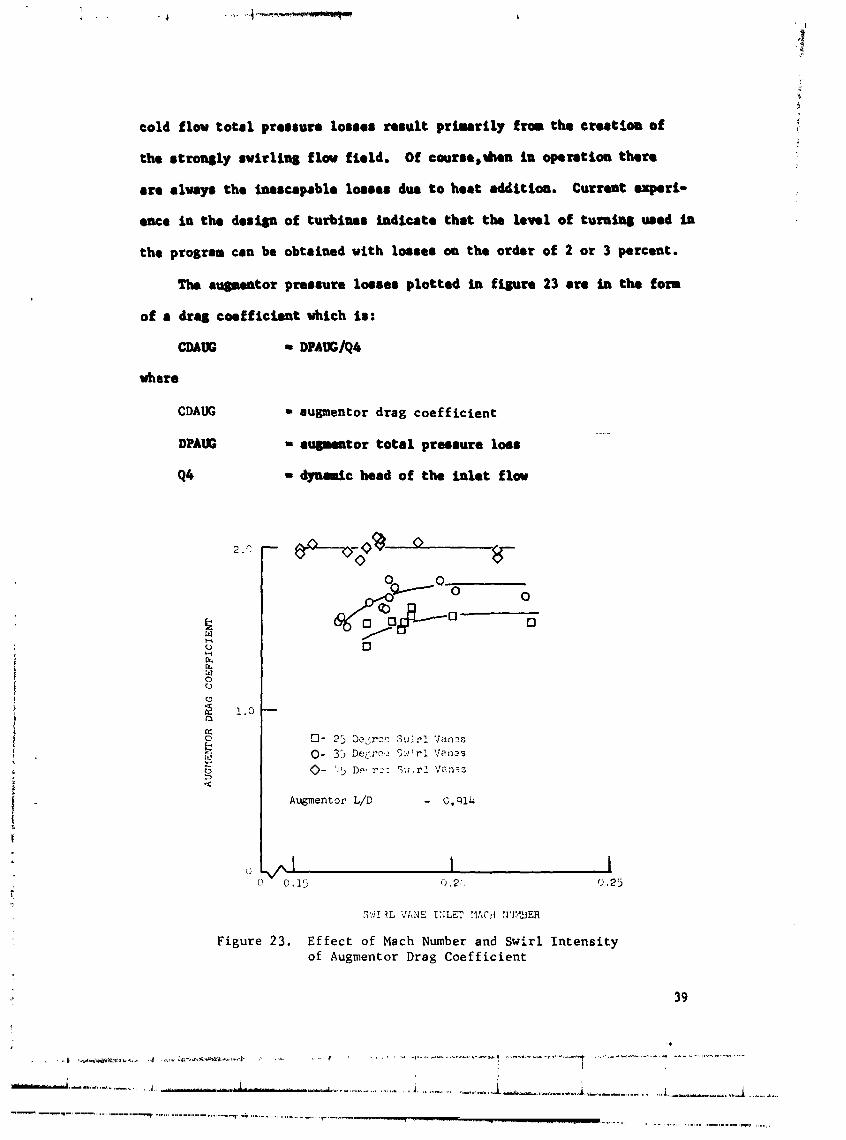
Ths augmentor prarrure 108880 plotted in figure 23 are in the fom
of a drag corf f icient which i r :
CMtS - DPAUC/Q4
where
CDAUG - augmentor drag coefficient DPAUG - rqpantor to t a l prerrure loor
Q4 = dynaic head of the in le t flaw
Augmentor L/D - C , W k
Figure 23. Effect of Mach Number and Swirl Intensity of Augmentor Drag Coefficient
Figure 2 3 shows the r e l a t i v e '.-:ct of increasing swirl in t ens i ty
on the augmentor drag coe l f ic ien t . ~ n e augmentor was equipped with the
smaller nozzle and i t s LID was C.914. A s expected, the highest losses
were obtained with the 0.79 radian (45 degree) vanes and the lowest
with the 0.44 radian (25 degree) vanes.
An obvious r e s u l t of the data i n f igure 2 3 is t h a t the losses were
high. This r e s u l t could negate any benef i t due t o t he improvement i n
combustim eff ic iency. With t h i s i n mind, a review of the data a s wel l
a s the r i g and s w i r l vane design was undertaken t o determine the
possible causes of the high measured pressure losses.
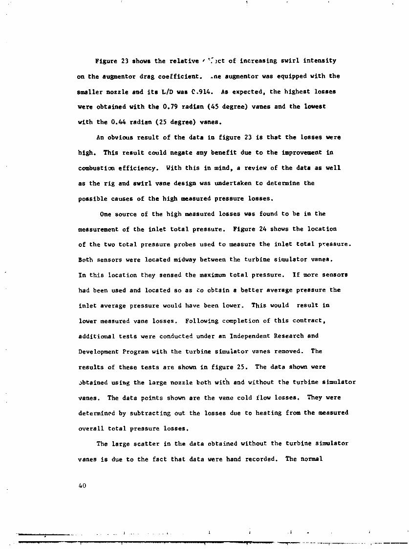
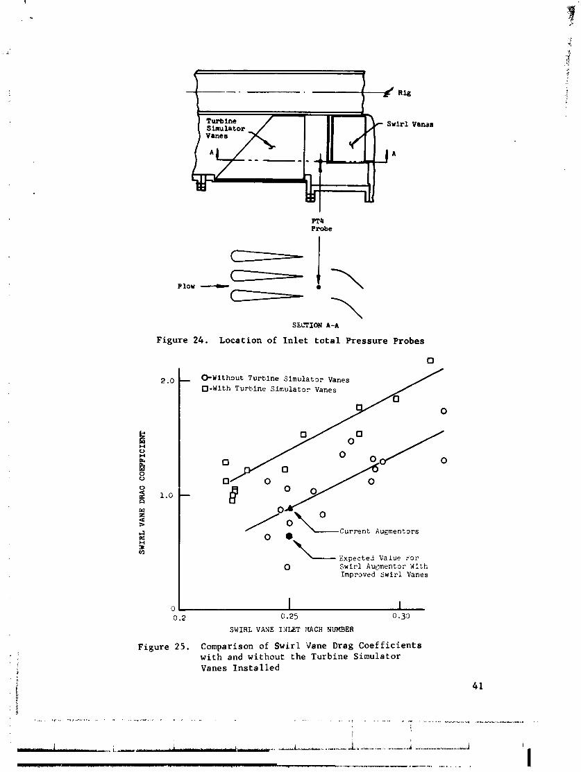
One source of the high measured losses was found t o be i n the
measurement of the i n l e t t o t a l pressure. Figure 2 4 shows the locat ion
of the two t o t a l pressure probes used t o measure the i n l e t t o t a l pressure.
Both sensors were located midway between the turbine simulator vanes.
I n t h i s location they sensed the maximum t o t a l pressure. I f more sensors
had been used and located so a s t o obtain a b e t t e r average pressure t he
i n l e t average pressure would have been lower. This would r e su l t i n
lower measured vane losses . Following completion of t h i s cont rac t ,
addi t ional t e s t s were conducted under an Independent Research and
Development Program with the turbine simulator vanes removed. The
r e su l t s of these t e s t s a r e shown i n f igure 25. The data shown were
abtained using the la rge nozzle both with and without the turbine simulator
vanes. The data points shown a r e the vane cold flow losses. They were
determined by subt rac t ing out the losses due t o heating from the measured
overa l l t o t a l pressure losses .
The large s c a t t e r i n the data obtained without the turbine simulator
vanes is due t o the f a c t t h a t data were hand recorded. The normal
PT4 Probe
SLiTION A-A
Figure 24. Location of I n l e t t o t a l Pressure Probes
0 - W i t h ~ u t T u r b i n e S i m u l a t o r Vanes 0 - W i t h T u r b i n e S i r n u l a t a r Vanes
0 + - -current Augmentors
\ \----- Expected Value k'or
0 Swirl Aupmentor With Improved S w i r l Vanes
0.2 0.25 0.33
SWIRL VASE ILJLET MACH NUMBER
Figure 2 5 . Comparison of Swirl Vane Drag Coef f i c i ents with and without the Turbine Simulator Vanes Ins ta l l ed
procedure was t o use a high speed data recording system which recorded
each channel ten times per second. The data were then averaged over
f i ve second in te rva ls . I n t h i s way a good average value of each parameter
was obtained. By hand recording the data each data channel was recorded
only one time. Consequently, a good average value f o r each data channel
was not obtained. Also, the recording time extended over approximately
t e n minutes, thereby, increasing the poss ib i l i t y f o r changes i n t he t e s t
conditions due t o a i r and fue l supply f luctuat ions. however, the data
do show t h a t removal of the turbine simulator vanes did cause a s i g n i f i -
cant drop i n the measured s w i r l vane pressure drop. Figure 25 shows
a typ ica l cold flow drag coef f ic ien t of cur ren t high performance augmentors.
As can be seen the t r u e drag coef f ic ien t of the experimental s w i r l aug-
mentor ( t he drag coe f f i c i en t obtained with the turbine simulator vanes
removed) is equal t o t h a t of current augmentors a t t he same conditions.
As mentioned e a r l i e r , t he s w i r l vanes were simple curved shee t metal
vanes. No attempt was made t o contour the vanes t o minimize vane p r o f i l e
losses. With well contoured vanes, cold flow drag coe f f i c i en t s on the
order of those shown on f igure 25 may be possible. This repreaents a
28 percent reduction i n the cold flow p res s t r e loss.
D. Effect of Swir l on Nozzle Thrust Coeff icient
Of immediate concern when considering the use of swir l ing Elow i n
augmentors i s what e f f e c t does swir l have on the performance of the
exhaust nozzle. Data reported i n the l i t e r a t u r e ( r e f . 4) show t h a t
swirl reduces the discharge coef f ic ien t . However, of more p rac t i ca l
concern i s the e f f e c t of s t i i r l on the t h r u s t coe f f i c i en t of the nozzle.
Because of i ts relevance t o the program discussed herein, the r e s u l t of
an Independent Research and Development Program which was conducted t o
obtain t h i s information is presented.
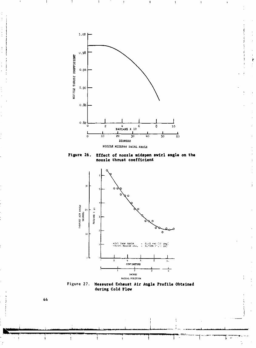
Figure 26 is a p lo t of n~ ,;le t h rus t coe f f i c i en t against the w d i a n
swirl angle a t the nozzle throat . The data were obtained using convergent
nozzles only. The throa t median swirl angle is defined a s the swirl
angle a t t he midspan radiue. As can be seen, f o r t h roa t midspan swirl
angles l e s s than 0.26 radian8 (15 deg) there is no e f f e c t on the nozzle
t h rus t coef f ic ien t . Above t n i s angle the thrua t coe f f i c i en t begins t o
f a l l rapidly.
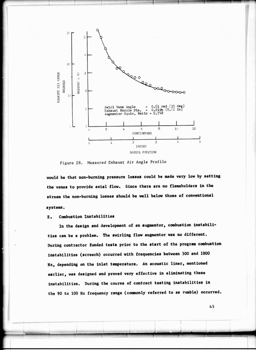
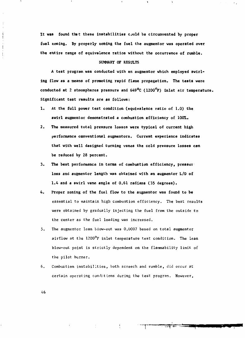
In f igures 27 and 28 a r e p lo t ted the nozzle t h roa t swirl angle
p ro f i l e s obtained using the 0.219 meter (8.62 inch) diameter nozzle.
The data of f igure 27 a r e cold flow data. The data of f igure 28 were
obtained a t an augmentor equivalence r a t i o of 0.75. The midspan was
approximately 0.055 meters (2.15 inches). Note t h a t a s the augmentor
equivalence r a t i o was increased the midspan swirl angle decreased from
approximately 0.34 radians t o 0.26 radians (19.5 t o 15 degrees). This
is t o be expected s ince increasing the combustor o u t l e t temperature, with a
fixed area nozzle, decreases the combustor i n l e t ve loc i ty , both a x i a l and
tangent ia l , so the tangent ia l ve loc i ty a t t h e exhaust nozzle is reduced
and because of the higher o u t l e t temperature t he a x i a l ve loc i ty a t the
nozzle is increased. With a var iab le area nozzle the midspan swirl angle
would s t i l l decrease because the increase i n gas temperature r a i s e s the
a x i a l veloci ty .
Therefore, i n a p rac t i ca l swir l augmentor system i t may be desirable
t o adjust the swirl vane angle i n order t o maintain the th rus t coe f f i c i en t
a t the non-swirl value. However, t h i s should not reduce performance s ince
l e s s swir l i s needed t o maintain high combustion e f f ic iency a s the equiva-
lence r a t i o is lowered. An addi t iona l benef i t of ad jus tab le swirl vanes
0
Figure 26.
DEOREES
NOZZLE MIDSPAN SWIRL ANGLE
Effect of nozzle midrpan rwirl angle on the nozzle thrust cocf f icient
. wirl Vane Angle - O.ol rad (?j de ) xhausl Nozzle Dia. - 0.3% (":T :nf
INCHES
RADIAL POSITION
Measured Exhaust Air Angle Profile Obtained during Cold Flow
Figure 2 7 .
It was found tbt these i n s t a b i l i t i e s c m l d be circumvented by proper
fue l zoning. By properly zoning the fue l the augmentor was operated over
the e n t i r e range of equivalence r a t i o s without the occurrence of rumble.
SUMMARY OF RESULTS
A t e s t program was conducted with an augmentor which employed swirl-
ing flow as a means of promoting rapid flame propagation. The t e s t s were
conducted a t 2 atmospheres pressure and 649'~ ( 1200%') i n l e t a i r temperature.
Signif icant t e s t r e s u l t s a r e a s follows:
A t the f u l l power t e s t condition (equivalence r a t i o of 1.0) the
swirl augmentor demonstrated a combustion e f f ic iency of 1007..
The meatlured t o t a l pressure losses were typ ica l of current high
performance c ~ v e n t i o n a l augmentors. Current experience ind ica tes
t h a t with well designed turning vanes the cold pressure losses can
be reduced by 28 percent.
The best performance i n terms of combustion e f f ic iency , pressur .
loss and augmentor length was obtained with an augmentor LID of
1.4 and a swirl vane angle of 0.61 radians (35 degrees).
Proper zoning of the fue l flow t o the augmentor was found t o be
e s s e n t i a l t o mainta in h igh combustion e f f i c i e n c y . The bes t r e s u l t s
were obtained by g radua l ly i n j e c t i n g t h e f u e l from t h e ou t s ide t o
t h e c e n t e r a s the f u e l loading was increased.
The augmentor l ean blow-out was 0.0007 based on t o t a l augmentor
a i r f l o w a t t h e 1200 '~ i n l e t temperature t e s t cond i t ion . The l ean
blow-out point i s s t r i c t l y dependent on the f lammabil i ty l i m i t of
t h e p i l o t burner.
Combust ion i n s t a b i l ; t i e s , both sc reech and rumble, d i d occur a t
c e r t a i n opera t ing cond i t ions dur ing t h e t e s t progr.?m. However,
screech in t h ~ frequency range between 500 and 1000 Hz was suppressed
with a conventional type acoustic i iner . Rumble i n the frequency
range between 90 and 100 Hz was avoided by proper distribution of
fuel t o the three fuel sprayrings.
APPENDIX A SWIRL AUGI1IE:NTOR I'EHFORMANCE CALCULATIONS
An engineering type formulation of the data reduction deck used to process
the swirl augmector data is presented. The formulation is not intendec! to present
the detailed logic performed by the performance deck. Instead, only the main
concepts and equations used to determine the various performance parameters
a r e given.
The gas is assunled to obey the perfect gas law dnd the flow processes
a r e described by the one dimensional, isentropic relations for compressible
fluid flow. A list of symbols is presented in Appendix B.
1. Airflow Metering Orifice Temperature
This i s the airflow total temperature at the primary airflow orifice. The
temperature i s the arithmetic average of two temperatures measured with
chromel/alumel thermocouples, o r
TORF (TORF1 1 TORF2)/2
2. Airflow Metering Orifice Pressure
The airflow metering orifice upstream pressure (PORF1) is measured
with one flange static pressure tap.
3. Airflow Metering Orifice Delta P
The airflow metering orifice delta P (DPORF) i s measured with a dif-
ferential pressure transducer connected across the orifice upstream and down-
stream flange taps.
4. Airflow Metering Orifice Diameter
The orifice diameter i s input to the performance deck. The f:imary
orifice diameter i s 0.18.4 meter (7.250 in. ).
5. Rig Total Airflow
This i s the totnl rig dry airflow as measured with the 0.181-meter (7.25-in.)
dinmcter orifice. Thr orifice mcnsures total massflow (dry airflow plus water
vapor) l)y 1h(. following equation:
The last terms in parenthesis correct the massflow for change8 in orifice area
due to thermal expansion.
The dry airflow rate is cslcul:~ted by subtracting the mass of water vapor
present in the inlet massflow. This procedure i s not a s simple a s it sounds
because the presence of water vapor in the mixture changes the gas properties
from those for dry air. Since the coefficients in equation (2) a r e based on dry
air , the massflow ca1cr:ated by it will he in error . This i s due to the changes
in gas properties brought ahout by the water vapor in the mixture. The pro-
cedure used to calculate the dry airflow rate i s a s follows. First the gas
properties for several mixtures of dry a i r and wnter vapor nre determined. The
gas constant for each mixture is given by:
Where \trW i s the mass of water vapor and W is the dry airflow rate. Since a W /\V i s the spccific humidity, the gas constant for the mixturc is:
W a
The spccific humiditv is crllculatcd from psychrometric charts for measured
valuet of wet and dry h 1 h tcmpcratures.
Tho spccific heat ratio for the mixturc of dry a i r and wnter is given by:
I'hc specific hcat for thr~ mixture, C is givcn by: pm'
From the above equations, the gas constant and spccific heat rat io for
severa l dry a i r and water vapor mixtures (specific humidities) were calculated.
Usir :: the following equation, the rat io of airf low computed using wet proper t ies
to that using dry propert ies, Cf, was determined fo r the VP. ious values of
spccific humidity.
Wnere P 2 i s ihe orif ice throat s ta t ic p ressure and P1 i s the orif ice upstream
pre~:ure. The subscript "a" r e fe r s to dry a i r and the subscript "m" to the dry
a i r and water vapor mixture. These calculations yielded a functional relation
between the m a s s ratio, Cf, and specific humidity which was approximated with
a l inear curve fit with the following result:
Computed 1210w lJsing Wet Proper t i e s 'f Computed Flow LTsing Dry Proper t i e s
Cf =- 1 - 0.3 1iVM
The calculated mnssflow is that calculnted l y equation (2). The dry airflow
temperature (TT-IA, s e e paragraph 30), p ressure (PT-IA, s e e paragraph 291,
dry airllow, spchcific humidity, and prehcatcr fucl flow the Mnch n u m l ~ e r i s
calculated I I ~ itcbrat ing on thc follow in^ equation:
The iteration i s ca r r i ed to Ihc accuracy limit of the computer which i s to seven
significant figures. The gas constant (R ) for the mixture of a i r , water vapor, 1
3 r d prcheatcr fucl was determined in the following manner:
R' (Wa + \VFPII) + Rw \V W
-t WFPII - \Vw
R ' i s n theoretical gas constant obtained from a propellant performance program
for the products of comt)ustion from the stand prcheater at the preheater operating
conditions.
The specific hent ratio ((L4M.l) for the mixture of a i r , water, and fuel was
determined a s follows:
This required calculation of the specific hcat for the mixture:
C ' (Wa + W F P A ) 4 C pw) C ~4 W a WFPII + Ww
C ' i s a theoretical specific hcat obtained from the propellant performance pro- P
gram for the products of coml)ustion from the stand prcheater at the preheater
operating conditions. C i s the specific hent for water vapor at the preheater Pw
exhaust temperature. The a rea , 5' i s the annular a r e a hetwtzn the 0.332
mete r (17 in. ) inner diameter of thc pilot case and the 0.102 mete r (I in.) center 2 3 l)od,y, o r , O.198m 1 I i n . ) Knowing the Mnch number the r ig inlet s ta t ic
p r e s s u r e i s given hy:
29. Rig Inlet Total Pressure
The rig inlet total pressure i s an arithmetic average of two pressures
measured with Kiel type total pressure probes. Therefore,
0 Rig Inlet Total Temperature
The rig inlet total temperature i s taken a s the ideal preheater outlet tem-
perature, TT4II)EAL. TTIIIIEAL is determined from an enthalpy balance across
the preheater. Therefore:
- H4 - '-'win a f win
- 1 1 t I I = H + H C
Where
"win - Enthalpy of the water vapor in the inlet flow
Ha Enthalpy of inlet a i r
I Enthalpy of fuel plus lower heating value of 18,370 Btu/lb m
IIC Enthalpy of coml~ustion products
Note the entha1p.y of the water was considered constant. This ar ises from the
assumption that the water does not enter into combustion process but i s ideally
mixed with the cornhustion products at the final mixture temperature. All the
al,ove enthalpies a r e total enthalpies nnd include any kinetic energy associated
with each component. Therefore,
rcn rranging
Trl. III)f+XI. TTC t P ) TTwlN(:z :!)
Thc dry a i r com1)ustion temperature, TTC, and the specific heat at constant
pressure, C ', a r e cnlculnted from a propellant performance program at the P
preheater inlet conditions. The mixture specific heat i s calculated in para-
graph 28. TTWIN is equal to TT3A.
The augmentor inlet temperature was also monitored with seven thermo-
couples. However, since the preheater outlet temperature distribution was
very nonuniform, the possibility of not obtaining a good averzge temperature
from only seven thermocouples precluded their use in the data reduction routine.
31. Swirl Vane Inlet Mach Number
The swirl vane inlet Mach number is calculated by iti-.rating on the follow-
ing equation:
As before the iteration is carried to the accuracy limit of the computer, The 2 2 swirl vane inlet area, A4, is O.0729m (113. O in.). The term SVFR is the
fraction of the total rig massflow passing through the swirl vanes. The remain-
ing massflow passes through the pilot. An initial value of 0 .96 is given to SV FR.
After the conditions downstream of the swirl vanes have been determined, a new
value of SVFR is calculated. All of the calculations a r e repeated using the new
value of SVFR. This process is repeated until satisfactory convergence between
the initial and final values of SVFR is obtained.
32. Augmentor Reference hlach Number
The reference Mach number is calculated by itcrating on the following
equation:
The iteratior is carricd to the accuracy limit of thc computer. The rcfcrcnce
area, At{I.: I" is taken as thc annular area bctwcen the 0.381 mctcr (15 in.) I
tliamctcr outer wall and 0.102 mctcr (4 in.) diameter centcrbody, o r O.1059m- '>
(164.15 in:).
3 .4ug1nentor Reference Velocity
The reference velocity is calculated from continuity using the following
equation:
'REF = W,(1 + HUM + FAPH)R4(TT4A)/(P~4A)AREF
34. Swirl Vane Inlet Velocity
The gas velocity at the swirl vanes is calculated by continuity as:
The specific heat ratio, GAYB, for the mixture of a ir , water and fuel is
given by:
CAM6 - C /(c - R6) ~6 PG
(54)
The gas constant, R for the mixture is given by: 6'
Rf(Wa + WFT + M'FPII) + Rw Ww
Wa + WFT + WFPH + Ww 6
Where R' is a theoretical gas constant obtained from a propellant performance
program for the products of combustion at the augmentor operating conditions.
The constant pressure specific heat, C for the mixtcrc is given by: ~ 6 '
The specific heat C' is obtained from a propellant pcrformance dcck at the P
nozzle exit conditions.
4(;. Augmentbr 'I'cmperature Ratio
Thc temperaturcb ratio across thc augmcntor is simply:
T I ~ A ' I ' I O 'I"I'(;,"I'T~A
47. I'ilot I'rc~ssurc~ 1,oss
'I'hcl pilot systcm prcssurcb loss is:
1 ) I ' l ~ Y . I(I"S4A - I'SI') il"I'4A] 100
48. Momentum Pressure Loss
The momentum pressure loss (loss due to combustion) was determined
from the relations for simple heating uf a perfect gas (Raylcigh line calculation)
in a constant a rea duct. The theoretical total pressure ratio (P0 /Pbn l = M4
i f the flow were heated from a state where M = M4, to a state where M = 1,
is determined from:
The Mach number. Mqe6, is evaluated at the plane of the zone 2. 3 and 4 spray-
bare using the temperature and pressure conditions at the swirl vane inlet,
The Mach number calculation is identical to that outlined in paragraph 32 for
the reference Mach number. The only difference is the area which is taken a s
2 the chamber cross-section at the plane of the spraybars o r 0. 114m2 (176.7 in. ).
The theoretical total ternperaturc ratio. ( T ~ / T ~ ) , = nl4 if the flow were . 1. heated from a state where n1 - h14. (; to a state where hl - 1,is dctcrmined from:
Knowing the exhaust total tcmpcrnturc and hence the exhaust-to-inlet tcm-
pcrature ratio, TT6 /'l"l'.IA,thc Mach number A15 just upstrcam of thc exhaust
nozzlc is cnlculatcd from:
TT4A TTG TTG P(GAMS+I)M: 'rf ''K = - 0 T:
Using Mach number, M5, and the pressure ratio PT4A/P; comri? , . l in equation 59,
the total pressure just upstream of the exhaust nozzle is then determined from:
The momentum pressure loss is then:
DPMOM .- PT4A - PT5IDEAL
Total System Pressure Loss
The total system pressure loss is simply:
PT4A - PTGA ( l l 4 A
Preheater Fuel-to- Air Ratio
The prchcater fuel-to-air ratio is simply:
FAPI1 - \!'FP11/(3600 \Va)
Prchcatcr Efficiency
Thc prcheatcr c*fficicmcy is given by:
I V i l l ('I"l'4rl - 'I'T3.4) i(TT-II DEAL - TTSA)
'I'hr idcal prchc:ilt~r outlrlt 1tmpc1raturc, TT.III)EAL, is gi1.w in paragraph 30.
52. ~tlcal I*,~3aust Total Tcmpcrature
The idcal cxhaust total tcmperaturcs i s calculatcd i n thc same manner a s
the prehcater idcal tcmpvralurc. The idcal dry cxhaust tot&: temperature is
calculatcd from the propellant performance program a s the temperature that
would result from combustion of dry a i r at the prcheater inlet temperature
TT3A and the total rig fuel flow (stand prcheatcr fucl, pilot fuel, and main com-
bustion zone fucl). This tcmpcr:lturc is then corrected for water vapor ic the
inlet airflow as follows. IJrom an cnthalpy balance:
Notc oncc again that the cnthalpy of the water is cons idcrd constant. Thc
enthalpies used in Lhe abovc equation a r c total enthalpies, which include the
kinetic energy associated with each component. Thus:
U' C TTBI IIEAI. brw cpw TT\VK + \I' C ' T T c T pG C P
Rearranging:
Cb9 the specific heat of the dry con~bcstion products is determined from the pro-
pellant performance program. The specific heat for the mixture, C is de- PG' termincd a s outlined ear l ier for air , water, and fucl mixtures (paragraph 45).
A s before, TT\VIN is equal to T'I'9A.
53. Augmcntor Efficiency
'She augnlcntor i-ombvstion efficiency is givcn bv:
TT6 - l"I'4A 3600 ($loss
TTGI I)I.:AI. - TT4A lHS70 \\'I>r
The cooling water heat loss, ()loss* iscalculatcd in Section 17.
1,:quation ( 6 H ) c:llculatcs thc augnwntor cf!'icicncy by comparing thc itlcal
tc1rnpcr;iturc risc to thc actual tcnipcraturcl r isc a s dctcrminctl from the c;~leu-
latctl v ~ l u c of '1"l'fi. 120r n portion o f the Lcsts thc ombu bust ion clficicncy was
also determined by sampling the exhaust gases for unburned hydrocarbons
and carbon monoxide. The combustion efficiency is then given by:
HVco(C0) + HVf(UHC) E FFMB - 100 - 100 - H V ~ lo3
where
CO = emission index of carbon monoxide
UHC = emission index of unburned hydrocarbons 7 HVco = heating value of carbon monoxide = 1.010 x 10 ~ o u l e s / k g
(1343 Btu/lbm)
HVf = heating value of the fuel = 4.273 x l o 7 Joules/kg (18,370 Btu/lb,)
54.
is:
Drag Coefficient - Vane Mach Number
The augmentor drag coefficient based on the swirl vane inlet Mach number
Where the dynamic head Q4 is given by:
55. Drag Coefficient - Rcfercnce Mach Number
The augmcntor drag cocfficient based on reference Mach number is:
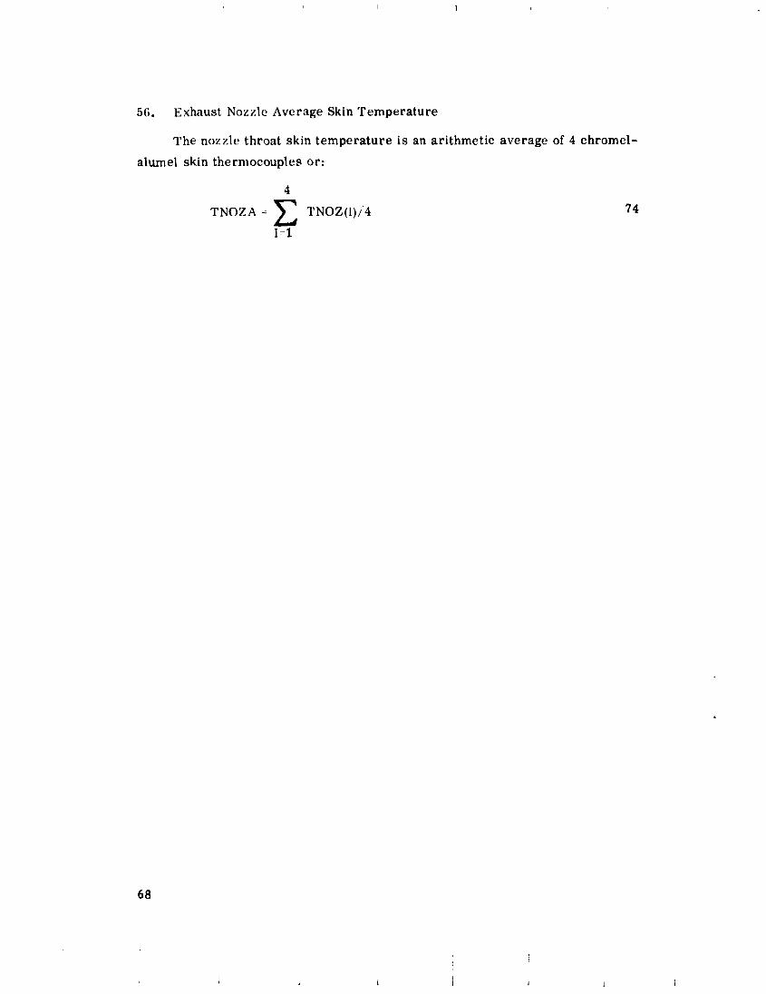
56. Exhaust Nozzle Average Skin Temperature
The nozzle throat skin temperature is an arithmetic average of 4 chromel-
alurnel skin thermocouples or:
4
TNOZA = TNOZ(I)/.4
1=1
APPENDIX B LIST OF SYMBOLS
A1
A2
A4
A4. 5
A4. 6
Acd
Anoz
A P
A ref
A*
BA FDP
BA F P l
BA FTTA
CDREF
Orifice upstream area
Orifice throat area
2 2 Swirl vane inlet area, 729 cm (113.0 in.)
2 2 Flow a rea upstream of the swirl vanes, 1380 cm (214.4 in.)
2 2 Flow area at the sprayrings, 1140 cm (176.6 in.)
2 2 Flow area at the nozzle inlet, 1140 cm (176.6 in.)
Nozzle throat effective area
Nozzle geometric area
2 2 Pilot zone inlet area, 24.47 cm (3.79 in. )
2 2 Augmentor reference area, 1059 cm (164.15 in. )
Flow area at Mach number equal 1.0
Back-up orifice delta pressure
Back-up orifice upstream pressure
Back-up orifice average temperature
Nozzle discharge coefficient
Augmentor drag coefficient based on swirl vane inlet Mach number
Augmentor drag coefficient based on reference Mach number
Ratio of computed flow using wet gas properties to that using dr,y gas properties
Spccific heat at constant pressure for dry a i r
Specific heat n t constant pressure for a mixture of dry a i r and water vapor
Specific heat at constant pressure for water vapor
Spccific heat n t constant pressure for n mixture of w a l c r vnpor and comlastion products at thc swirl vane inlet
DNOZ
dPAUC;
DP FPZ
DPFZ2
DPFZ3
DPFZ4
DPMOM
DPOR F
DPPZ
DPSV
EFFMB
EFFPH
FA 2
FA 3
FA4
FA 0
FA PH
FA P;!
G
GAM4
GAM6
Specific heat at constant pressure for a mixture of water vapor and combustion products at the nozzle exit
Specific heat at constant pressure for dry combustion products
Nozzle diameter - cold
Augmentor total pressure loss
Pilot zone fuel pressure drop
Zone 2 fuel pressure drop
Zone 3 fuel przssure drop
Zone 4 fuel pressure drop
Momentum pressure drop (pressure drop due to heating)
Primary airflow orifice pressure drop
Pilot zone a i r pressure loss
Swirl vane pressure loss
Pressure drop across cooling water flow measuring orifice
Augmentor combustion efficiency
Preheater combustion efficiency
Augmentor fuellair ratio due to zone 2 fuel flow
Augmentor fuel./air ratio due to zone 3 fuel flow
Augmentor fuel/nir ratio due to zone ." f w l flow
Augmentor fuel /a i r rntio
Prehenter fuel,/air ratio
Pilot zone fuel/air rntio
Standard acceleration due to gravity
Specific heat ratio at swirl vane inlet
Specific heat ratio at nozzle exit
M4
M4. 5
M4. 6
Iq5
M6
M P z
ref
P1
P2
P B A R
PFPZ
POR I:l
Swirl intensity a t the pilot inner wall, defined in Equation (41)
I'nthalpy of entering a i r
Ehthalpy of combustion products
Knthalpy of fuel including heat of combustion
Enthalpy of gas a t swir l vane inlet
I'nthalpy of gas at nozzle exit
Specific humidity of entering a i r
Enthalpy of entering water vapor
Combustion zone length
Comlmstion zone length-to-diameter rat io
Swirl vane inlet hlach number
Mach n u m l ~ e r just upstream of the swir l vailes
Mach number at the plane of the fuel sprayr ings
Exhaust n072le iniet Mach number
Nozzle exit Mach number
Mach number through pilot swi r l e r
Augmentor reference Mach number
Orifice upst ream pressure
Orifice throat p r e s s u r e
A tmosphcric p r e s s u r e
Pilot zone fuel p r e s s u r e
Zone 2 fuel p ressure
Zone 3 fuel p ressure
%one I fuel p ressure
Totnl pr thssure at Mach number unity
P r i m a r y orif icc upstream p r e s s u r e
Total to s ta t ic p ressurc rat io
PS4.5 - Static pressure just upstream of swirl vanes
PS5A - h'ozzle inlet static pressure
PSP - Pilot zone static pressure
PT4A - Augmentor inlet total pressure
PTEiIDEAL - Ideal total pressure at nozzle inlet
PTGA - Exhaust nozzle total pressure
Q4 - Swirl vane dynamic head
Qloss - Heat rejected to cooling water
QREF - Reference dynamic head
R - Pilot inner wall radius
Ra - Gas constant for dry a i r
R - Gas constant for a mixture of dry a i r and water vapor m
R - Gas constant for water vapor W
R4 - Gas constant at the swirl vane inlet
- Gas constant at the nozzle exit
H ' - Gas constant for the dry combustion products
SV FR - Fraction of tot.11 rig massflow passing through the swirl vanes
TNOZA - Exhaust nozzle wall temperature
T* - Total temperature at Mach number unity C
TORF - Primary orifice temperature
TRATIO - Ratio of outlet to inlet temperhture
TT3A - Prchcater inlet total temperature
TT4A - Rig inlet total temperature
TTdIDEAI, - Ideal prehcntcr outlet temperature
TTG - Augnentor outlet total temperature
TT6IDEAL - Ideal nugmentor outlet temperature
TTC
TWIN
TWORF
Wa
W C
WCW
WFPZ
W W
SMT
Ideal combustion temperature-dry
Temperature of entering water vapor
Cooling water inlet temperature
Cooling water outlet temperature
Swirl vane inlet velocity
Tangential velocity at the pilot inner wall
Reference velocity
Dry airflow rate
Dry flowrate of combustion products
Cooling water flowrate
Pilot Lofie fuel flow
Total augmentor fuel flow
Zone 2 fuel flow
Zone 3 fuel flow
Zone 4 fuel flow
Pilot zone airflow
Total massflow at the exhaust nozzle
-.." ~vat ,or vapor flowrate
Tangential Mach number at the exhaust nozzle exit
Swirl vane angle
Specific heat nt constant pressure of dry a i r
Specific heat at constant pressure of water vapor and dry a i r