+ All Categories
Home > Documents > Final Report Penta

Final Report Penta

Date post: 08-Feb-2017
Category:
Upload: rahul-kumar
View: 393 times
Download: 0 times
Share this document with a friend
39
Internship Report 2 nd May 2014-11 th July 2014 Study on Manufacturing of Cement and NOx Reduction in Cement Industry Submitted to: PENTA India Cement & Minerals Pvt. Ltd. Mumbai, India Submitted by: Rahul Kumar 3 rd year Undergraduate Chemical Engineering, IIT Bombay
Transcript

Internship Report

2nd May 2014-11th July 2014

Study on Manufacturing of Cement and NOx

Reduction in Cement Industry

Submitted to:

PENTA India Cement &

Minerals Pvt. Ltd.

Mumbai, India

Submitted by:

Rahul Kumar

3rd year Undergraduate Chemical Engineering, IIT Bombay

Content

UNIT 1: Introduction to Cement and Manufacturing Process

UNIT 2: Cement Plant Machinery

UNIT 3: Introduction to NOx and how does it form?

UNIT 4: NOx regulations in different Countries

UNIT 5: NOx Control Approach

UNIT 6: Cost Analysis of Present NOx reduction Technologies

UNIT 7: Clearances Required For Setting up a Cement Plant

UNIT 1: Introduction to Cement and Manufacturing Process

Introduction of Cement

What is cement?

Cement is a binding material which is used in construction.

What are the raw materials?

Four chemical compounds like Calcium Oxide, Iron Oxide, Silicon dioxide and Alumina are required

to produce the chemical composition of cement. These compounds are obtained from Limestone,

Pyrite Cinder, Diatomite and Bauxite minerals respectively.

How is it made?

Cement is the product obtained by pulverizing clinker and mixing desired amount of additives (like

gypsum etc.) afterwards to the clinker, whereas clinker is obtained by pyroprocessing raw materials

consisting of lime, silicate, alumina and iron oxide.

When it is mixed with water it forms a paste which hardens and binds aggregates (sand, gravel)

together to form hard durable mass called concrete.

Composition of Raw Materials and Clinker

Limestone Diaotomite Bauxite

Pyrites

Cinders Clinker

LOI 40 6.2 15-20 0 0.5-3

SiO2 3-7 77 16-22 6.6-25 16-26

Al2O3 .7-1.28 9.6 44-58 2-16 4-8

Fe2O3 .66-1.47

10-16 62-87 2-5

CaO 49-52 0.3 2-4 .7-.9 58-67

MgO .6-1.48 0.9 .2-1 .2-2 1-5

SO3 0-1 0 0 .8-8 .1-2.5

Na2O + K2O 0-.4 1.5 0 0 0-1

Important Types of cement

Ordinary Portland cement (OPC)- The product obtained by mixing gypsum and grinded clinker is

called OPC. This is the most common type of Portland cement.

Portland Pozzolanic cement (PPC)- The Portland Pozzolanic Cement is a kind of Blended Cement

which is produced by either grinding of OPC clinker along with gypsum as well as Pozzolanic

materials* in certain proportions or grinding the OPC clinker, gypsum and Pozzolanic materials

separately and thoroughly blending them in certain proportions.

One important reason to manufacture PPC is to reduce the energy requirement in cement industry.

Major portion of energy is lost in manufacturing clinker and if some flyash around 20 % is mixed with

clinker to manufacture PPC cement, the energy requirement can be reduced to 80 % in case of PPC

in comparison with OPC.

*A Pozzolanic material is an siliceous or siliceous and aluminous material which, in itself, possesses

little or no cementitious value but which will, in finely divided form and in the presence of water,

react chemically with Calcium Hydroxide at ordinary temperature to form compounds possessing

cementitious properties.

Grade of Cement

The grade is the index of strength measured as the compressive strength measured in laboratory of

the cement cubes (of 50 cm2 sides) on 28th day as 43 MPa (Grade 43) & 53 MPa (Grade 53). There is

also Grade 33 Portland cement available. Higher the strength stronger is the cement, obviously and

more expensive too.

Typical constituents of Portland clinker plus gypsum Cement Chemists Notation under CCN

Clinker CCN Mass %

(CaO)3 · SiO2 C3S (Alite) 45–75%

(CaO)2 · SiO2 C2S (Belite) 7–32%

(CaO)3 · Al2O3 C3A 0–13%

(CaO)4 · Al2O3 · Fe2O3 C4AF 0–18%

CaSO4 · 2 H2O (Gypsum) 2–10%

How Clinker is obtained?

Clinker reactions below 1300°C

Temp. Range Product

Drying of raw materials 100 - 300°C free water evaporates and

release of adsorbed

and crystal water

Decomposition of calcite

(calcining)

500 - 900°C free lime (CaO)

Decomposition of pollysilicates 300 - 900°C dehydroxilated,

amorphous material

Formation of first clinker phases > 900°C Belite, aluminates

(different phases),

Ferrites

Formation of first melt phases > 1000°C

Clinker reactions between 1300°C and 1450°C

1. Melting reactions

- Melting of primary aluminates and ferrites phases

- Melting of part of the early formed belite

2. Formation of new phases

Reaction of melt, free lime, unreacted silica and remaining belite to alite

3. Polymorphic transformation of belite

4. Recrystallization of alite and belite

5. Nodulization (clinkering)

Clinker reactions during cooling

1. Crystallization of the melt. Products: aluminates (C3A) and ferrites (C4AF)

2. Polymorphic transformations of alite and belite

If cooling is too slow

3. Back reaction of alite to belite + lime

4. Recrystallization aluminates and ferrites

Thus after cooling, clinker is obtained which is then processed to manufacture cement.

Manufacturing of Cement

First of all the raw materials are grinded and then they are collected in different silos. Thereafter

they are sent to homogenizing silos where they are mixed in desired proportion to get the desired

concentration of different raw minerals in the cement. Then they are processed at high temperature

to get clinker.

Raw Material Transfer from Quarry to Different Silos

1. Raw Material Grinding and Transfer from Quarry to

Different Silos

2.Raw Material Transfer from Different Silos to Homogeneous Silo

3.Pyroprocessing and Finish Milling

Cement

Raw Material Transfer from Different Silos to Homogeneous Silo

Pyroprocessing and Finish Milling

UNIT 2: Cement Plant Machinery

Material and Gas Flow

Gas Suspension Preheater

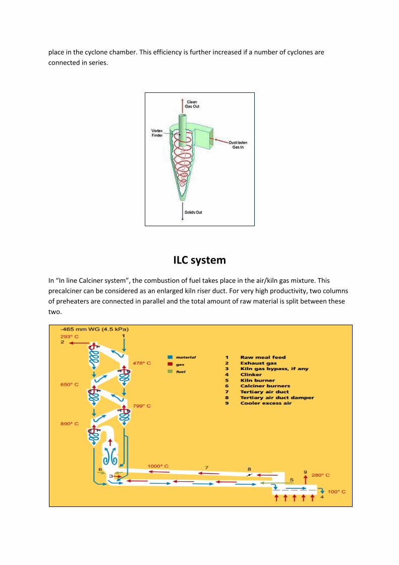
The key component of the gas-suspension preheater is the cyclone. A cyclone is a conical vessel into

which a dust-bearing gas-stream is passed tangentially thus generating vortex. Solid dust comes

from the bottom due to gravity and gas passes out from the top. The column of cyclones is very

efficient in exchanging heat between hot gas and relatively cool raw mill. Almost all the heat transfer

takes place in the vertical metallic pipe between consecutive cyclones and the entire dedusting takes

place in the cyclone chamber. This efficiency is further increased if a number of cyclones are

connected in series.
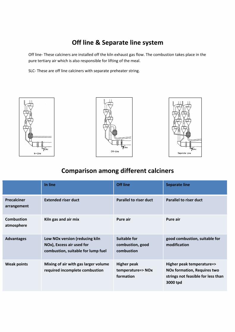
ILC system

In “In line Calciner system”, the combustion of fuel takes place in the air/kiln gas mixture. This

precalciner can be considered as an enlarged kiln riser duct. For very high productivity, two columns

of preheaters are connected in parallel and the total amount of raw material is split between these

two.

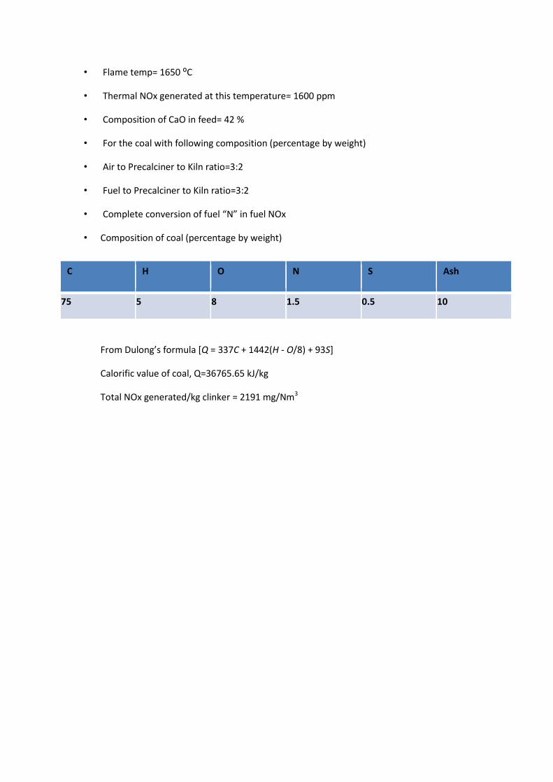
Off line & Separate line system

Off line- These calciners are installed off the kiln exhaust gas flow. The combustion takes place in the

pure tertiary air which is also responsible for lifting of the meal.

SLC- These are off line calciners with separate preheater string.

Comparison among different calciners

In line Off line Separate line

Precalciner

arrangement

Extended riser duct Parallel to riser duct Parallel to riser duct

Combustion

atmosphere

Kiln gas and air mix Pure air Pure air

Advantages Low NOx version (reducing kiln

NOx), Excess air used for

combustion, suitable for lump fuel

Suitable for

combustion, good

combustion

good combustion, suitable for

modification

Weak points Mixing of air with gas larger volume

required incomplete combustion

Higher peak

temperature=> NOx

formation

Higher peak temperature=>

NOx formation, Requires two

strings not feasible for less than

3000 tpd

Rotary Kiln

Rotary kiln is the heart of the cement industry. Up to 90 % calcination of raw material does take

place in preheater. Rest of the calcination and all the chemical transformations occur in kiln only.

Grate cooler

A grate cooler can be regarded as a simple heat exchanger through which the clinker passes

crosscurrent to the cooling air flow and a direct heat transfer takes place between the hot clinker

and the cold cooling air. The hot clinker from kiln is discharged in the grate cooler at temperature of

1250°C–1400°C.Finally clinker comes out of the cooler at around 100°C.

UNIT 3: Introduction to NOx and How Does It Form?

NOx Formation in Cement Industry

NOx is referred collectively to nitric oxide (NO) and nitrogen dioxide (N02). NOx is an air pollutant (if

it’s in excess) which can cause diseases related to respiration and in critical concentration it can be

fatal.

NOx formation in cement industry takes place in four possible ways-

1. Thermal NOx (The oxidation of N2 in combustion air)

2. Fuel NOx (The oxidation of N in fuel)

3. Feed NOx (The oxidation of N in feed)

4. Prompt NOx

Research has shown that the predominant nitrogen oxide species in cement kiln exhaust gases is NO.

Typically, more than 90% of NOx is NO, with NO2 making up the remainder.

The most important are the first two. We will discuss only the first two here.

Thermal NOx formation

NOx formed in the high-temperature environment of the main combustion zone of a cement kiln is

"thermal NOx“. Significant oxidation of nitrogen takes place in oxidizing flames with a temperature

greater than about 1,200°C. In the kiln, high combustion gas temperatures are necessary because

the product must be heated to about 2,650°F (1,450 °C) by the hot gases and because the heat is

transferred primarily by radiation from the gas to the feed. So, combustion gas temperature reaches

3,200°F (1,760°C) approximately.

Mechanism-

O + N2 ↔ N + NO

K1= forward rate constant= 1.8* 10 ^8 exp(-38370/T) m3/gmol.s

K-1=backward rate constant= 3.8*10^7 exp (-425/T) m3/gmol.s

N + O2 ↔ O + NO

K2= 1.8* 10 ^4*T* exp(-4680/T) m3/gmol.s

K-2=3.8* 10^3 *T*exp (-20820/T) m3/gmol.s

N + OH ↔ H + NO

Following factors determine the concentration of NO in the kiln gases leaving the burning zone-

1. Max theoretical (adiabatic) flame temperature

2. Flame shape

3. Excess air rate

4. Max necessary material temperature

5. Material retention time in burning zone

6. Gas retention time in burning zone

d[NO]/dt = k1[O][N2] +k2[N][O2] +k3[N][OH]−k−1[NO][N]

− k−2[NO][O]−k−3[NO][H]

The first column shows the concentration of NOx in ambient air whereas the other column contains

the NOx concentration in flue gas condition where concentration of Oxygen is 3.3 % and that of

Nitrogen is 76%.

Variation of Gas Concentration inside the Kiln

Variation of NOx Concentration with Flame Temperature

Energy Balance of an ILC System

Conclusion- Roughly 700-720 Kcal/kg Clinker is required in a cement industry.

Fuel NOx Generation

NOx resulting from the oxidation of nitrogen compounds in fuel is called fuel NOx. Fuel NOx

generally forms at relatively lower temperature between 815°C to 1090 °C and temperature of gases

in Precalciner is within this range.

Factors on which fuel NOx formation depends-

1. N-content in fuel

2. Oxygen level in combustion zone

3. Initial NO concentration in combustion zone

4. Volatile component in solid fuel

5. Temperature in secondary zone

Cooler

ILC Kiln

Heat of reaction

400-420 kcal/kg

CPreheaterHeat in smoke and

Dust from preheater

315 C

140 kcal/kg cl

Coal Firing

700-720 kcal/kg cl

Heat out with

clinker= 20 kcal/kg

Cooler excess air

250 C

~80 kcal/kg C

Kiln radiation loss

20 kcal/kg cl

60 % calciner

40% kiln

Preheater

Radiation Loss

30 kcal/kg

Heat in with clinker

~ 8 kcal/kg cl

Cooler radiation loss

7 kcal/kg cl

Fuel NOx Generation

A higher volatile content in the fuel tends to reduce the percentage of fuel nitrogen converted

into NO. An increase in the temperature of the secondary combustion zone will reduce the net

NO formation. A temperatures between about 1,500°F (815°C) and 2,000°F (1 ,090°C), the

following reactions may take place:

"N" + O NO (approaching 815° C)

"N" + NO N2 + O (approaching 1090° C)

Since the rate of reaction 2 increases more rapidly than the rate of reaction 1 as the

temperature increases, higher temperatures (between 1500°F and 2000°F [815°C and 1090°C])

may reduce NOx emissions in secondary combustion zones.

Fuel NOx Variation with Oxygen

Quantification of Fuel NOx

Assumptions:

• energy needed/kg of Clinker = 688 kcal

• Excess percentage air= 10 %

• Flame temp= 1650 ⁰C

• Thermal NOx generated at this temperature= 1600 ppm

• Composition of CaO in feed= 42 %

• For the coal with following composition (percentage by weight)

• Air to Precalciner to Kiln ratio=3:2

• Fuel to Precalciner to Kiln ratio=3:2

• Complete conversion of fuel “N” in fuel NOx

• Composition of coal (percentage by weight)

From Dulong’s formula [Q = 337C + 1442(H - O/8) + 93S]

Calorific value of coal, Q=36765.65 kJ/kg

Total NOx generated/kg clinker = 2191 mg/Nm3

C H O N S Ash

75 5 8 1.5 0.5 10

UNIT 4: NOx regulations in different Countries

NOx Regulations in Different Countries

COUNTRY/REGION NOx limit (mg/Nm^3) COUNTRY/REGION NOx limit

(mg/Nm^3)

Australia (New South Wales, AF) 800 Colombia

(Conventional fuels )

800

Australia (Victoria) 3600g/min Colombia (Non-

hazardous AF)

200

Austria 500 Colombia

(hazardous AF)

550

Bolivia 1800 Egypt 600

Brazil By state European union 200-450

Canada By Province Germany (Current) 500

Chile (AF plants only) None Germany (From 1

June 2018)

200

China (2008 regs.) 800 India (Proposed by

Industry)

1200 (existing),800

(new)

China (2013 regs, Existing Plant) 400 India (Proposed by

authorities)

1000 (existing), 600

(new)

China (2013 regs, New Plants 400 Indonesia 1000

COUNTRY/REGION NOx limit (mg/Nm^3) COUNTRY/REGION NOx limit (mg/Nm^3)

Indonesia (proposed) 800 South Africa (AF, 1200

built pre-2004)

Lebanon 2500 (old), 1500 (new) South Africa ( built

post-2004)

1500

Nigeria (New plants) 600-800 (fuel dep.) South Africa (AF,

built pre-2004)

2000

Nigeria (Existing plants) 1200 (old or wet) Switzerland 800

Norway (Norcem Brevik) 800 Turkey 1200

Norway (Norcem Kjopsvik) 800 Turkey (from 2015) 400

Pakistan 400-1200 (fuel dep.) UAE 400

Russia By plant UK 900

Saudi Arabia 600 (1 hr avg) US (one particular

plant)

800 (500 future)

South Africa (AF, built post -

2004)

2000 US (form 9 Sep

2015)

1.5 lb/ ton clinker

UNIT 5: NOx Control Approach

NOx Control Approach

1. Process control-Here modifications are made to improve fuel efficiency and kiln operational

stability thereby reducing NOx formation

2. Combustion modification-Controlling combustion to reduce NOX formation

3. Post combustion control-Destroy the NOX formed after combustion

Process control

• Fuel conversions such as changing from natural gas firing to coal firing have the potential to

reduce NOx by as much as 60%.

• Reducing the amount of moisture in the raw feed

• Modifications to improve thermal efficiency-

o Elimination of excess air infiltration

o Installation of high efficiency cyclones in preheater kilns

• Modifications to clinker coolers to improve heat recovery and cooler efficiency to reduce

fuel consumption:

o Revisions to grate layout and type of grate

o Complete replacement of under grate fans

o installation of air-to-air heat exchangers on cooler vent air systems

o Enlargement of clinker cooler throats to reduce secondary air velocity into the kiln

• Returning as much CKD (cement kiln dust) as possible to the kiln system (without adversely

affecting product quality) to reduce fuel consumption

• Installing or upgrading computer control of the kiln systems

• Installing or upgrading kiln system sensors and instrumentation.

Combustion modification

Combustion modification will include modification of fuel firing systems, installing new burners,

revisions to burner pipes, riser fuel burning, mid-kiln firing, and reduction in amount of excess air.

o Low NOx burner

o Secondary combustion

o Staged combustion

Low NOx Burners (LNB)

A burner designed to provide fuel and air staging and mixing to minimize peak flame temperatures

and so reduce NOx emissions. Also Conversion from a direct coal firing system to an indirect firing

system is necessary before a low NOx burner can be installed.

Features of low NOx burner:

o Precise mixing of fuel and air is used to keep the flame temperature low (Indirect

firing)

o dissipate heat quickly through the use of low excess air i.e. reduced residence time

in the high-temperature zone

o off stoichiometric combustion and combustion gas recirculation

By conversion to indirect-firing with a low NOx burner, NOx reduction achievable to 10-15%

Direct firing

In direct firing system, coal is milled on line and is directly fed to the kiln. The primary air is used to

dry the coal.

Indirect firing

In indirect firing system, milling is done offline and neither primary air nor coal is fed directly to the

kiln.

Secondary Combustion

Mid-kiln firing (for long dry Kiln)—Secondary firing in kiln systems by injecting fuel at an

intermediate point in the kiln system using a specially designed fuel injection mechanism for the

purpose of decreasing NOx emissions through—

o The burning of part of the fuel at a lower temperature

o The creation of reducing conditions at the point of initial combustion

Riser fuel burning in Preheater Kiln

Gas temperatures in the combustion zone of preheater riser ducts and in Precalciner vessels are

about 1,600°F - 1,800°F (870°C - 980°C). The formation of thermal NOx is negligible and fuel NOx will

predominate.

The following factors influence how much, if any, NO is formed in the secondary firing zones

(Precalciners or preheaters with riser duct firing):

o The type of fuel

o The amount of fuel nitrogen

o The NO content of the kiln gases

o The volatile content of the fuel

o The temperature in the secondary combustion zone

o The available oxygen

Secondary Combustion in Precalciner Kiln

In a Precalciner kiln without a bypass to control alkalis, sulfur or chlorides, typically 60% of the fuel is

burned in the Precalciner. Precalciner kiln operation is more stable because

o Approximately 90% of the CO2 in the feed is removed prior to the feed entering the

kiln.

o Only 40% - 50% of the fuel is burned in the high temperature environment of the

burning zone.

o Overall NOx emissions are typically lower for a Precalciner kiln than for other kiln

types.

Staged Combustion (SC)

Staged combustion occurs in two zones. In the first combustion area, fuel is fired with less than

stoichiometric amount of air, creating a fuel-rich condition near the primary flame. In the second

area, the rest of the combustion air is introduced to complete the fuel consumption. The deficiency

of O2 in the first zone and the low temperature in the second zone both contribute to a reduction in

NOx formation.

Low NOx Precalciner

In a Precalciner kiln without a bypass to control alkalis, sulfur or chlorides, typically 60% of the

fuel is burned in the Precalciner. Precalciner kiln operation is more stable because

o Approximately 90% of the CO2 in the feed is removed prior to the feed entering the

kiln.

o Only 40% - 50% of the fuel is burned in the high temperature environment of the

burning zone.

o Overall NOx emissions are typically lower for a Precalciner kiln than for other kiln

types.

RSP (Reinforced Suspension Preheater)

Working Principle of RSP

Post combustion control

• Selective Noncatalytic Reduction (SNCR)

o Ammonia-Based SNCR

o Urea Based SNCR

o BioSolids Injection (BSI) Based SNCR

• Selective Catalytic Reduction

• Catalytic Fabric Filtration

• Nonthermal Plasma

Selective Noncatalytic Reduction (SNCR)

The reagent, typically NH3 or urea, is injected into the kiln system at a location with an

appropriate temperature window, approximately 1,6OO°F to 2,OOO°F (870°C to 1,090°C). At

higher temperatures, the reagents will form additional NOx; at lower temperatures, the

reactions proceed slowly and substantial amounts of unreacted ammonia will escape.

It is believed that NOx reduction efficiency of SNCR depends on:

o Temperature

o Residence time

o NOx concentration in the flue gas

o Ammonia concentration in the flue gas

NH2CONH2 + H2O → 2NH3 + CO2 [reagent as Urea]

4 NO + 4 NH3 + O2 → 4 N2 + 6 H2O [reagent as Ammonia]

SNCR-NH3

The optimum temperature range for NO removal is between 900°C and 1000°C (1650°F and 1832°F).

Under optimum conditions about 1 mole of NH3 is required for 1 mole of NO. However, the amount

of NH3 is critically dependent on the reaction temperature. About 0.8 moles of NO is reduced with 1

mole of NH3 at 970°C (1 778°F). At higher and lower temperatures, less NO is reduced per mole of

NH3. An NH3 excess of more than 100% has little additional effect on NO reduction but NH3 escape

(ammonia slip) increases sharply with increasing molar ratios of NH3 to NO.

BioSolids Injection (BSI) Based SNCR

BSI uses dewatered sewage sludge as the reagent in a SNCR application on a Precalciner kiln.

Operating conditions which affect the performance of BSI for NOx reduction are:

o Temperature (1 700°F optimal)

o Residence time ( > 0.5 seconds desirable),

o Inlet NOx concentration,

o Inlet CO concentration,

o NH3:NOx molar ratio, and

o Mixing effectiveness

Selective Catalytic Reduction (SCR)

SCR uses ammonia, in the presence of a catalyst, to selectively reduce NOx emissions from exhaust

gases. Titanium Dioxide (TiO2) and Vanadium Pentoxide (V2O5) are commonly used as catalysts

because they are more resistant to poisoning by SO2. The optimum temperature for SCR depends on

the catalyst but is usually between 300°C and 450°C (570°F and 840°F).

SNCR & SCR with Preheater

Catalytic Fabric Filtration

This technology uses a catalyst coated onto a high temperature glass fabric dust collector bag.

Ammonia is used as the reagent and both NOx and particulate emissions are controlled. The

operating temperature range must remain between 650°F and 725°F (340°C and 385°C). This

temperature range may cause dioxin formation. At temperatures below 650°F (34O°C), ammonia slip

can become a problem. At temperatures above 750°F (400°C) the catalyst is permanently

deactivated. This technology is in the prototype stage.

Nonthermal Plasma

This technology is very costly. So, it’s not practical to use. It uses room temperature plasma for

reduction of NOx.

UNIT 6: Cost Effectiveness of Different NOx Reduction

Technologies

ACHIEVABLE NOX REDUCTIONS WITH VARIOUS CONTROL TECHNIQUES

NOx Control Technique Theoretical

Reduction

(Percentage)

Industry Verified

Reduction (Percentage)

Process Control 25 0-20

Combustion

Modifications

- Indirect Firing and Low

NOx Burner

20-30 0-15

Secondary Combustion -

Mid-Kiln Firing Of Tires

and Riser Duct Firing

20-40 0-30

staged Combustion - Low

NOx Precalciner

30-45 30-40

Post combustion Control

SNCR -Ammonia

-Urea

-BioSolid

30-70 15-75

15-50

30-50

* 1 short ton=0.907 metric ton

Cost Comparison among Different Reduction Techniques

* Effectiveness in US $ per ton of NOx removed

# Conversion to indirect firing with Low NOx Burners

^ Conversion to Low NOx Precalciner

Kiln Type Capacity

(t/h)

NOx effectiveness*

(Combustion

Modifications #)

NOx

effectiveness*

(Staged

combustion ^)

NOx

effectiveness*

(SNCR-NH3)

NOx

effectiveness*

(SNCR-BioSolid)

Preheater 36 8918 - 3214 -

Preheater 64 6726 - 2491 -

Precalciner 91 8343 3444 2683 5228

Precalciner 136 6853 2968 3292 6114

Cost Effectiveness Comparison among Different Reduction Techniques in Precalciner Kiln

Type

Cost Effectiveness Comparison among Different Reduction Techniques in Preheater Kiln

Type

0

1000

2000

3000

4000

5000

6000

7000

8000

9000

91 tph 136 tph

Comb.Modification

staged comb.

SNCR-NH3

SNCR Biosolids

0

2000

4000

6000

8000

10000

36 tph 64 tph

Comb.Modification

SNCR-NH3

UNIT 7: Clearances Required For Setting up a Cement Plant

Approvals/Clearances Required Department to be Approached and Consulted

Incorporation of Company Registrar of Companies

Registration/IEM/Industrial license DIC for SSI/SIA for large and medium

industries

Allotment of land State DI/SIDC/Infrastructure Corporation /SSIDC

Permission for land use (in case industry is located

outside an industrial area)

a. State DI

b. Dept. of Town and Country

Planning

Trade license or Trade Certificate of Enlistments Concerned ‘Gram Panchayat’, ‘Municipality’ or

‘Notified Authority’

Approval of construction activity and building plan a. Town and country planning

b. Municipal and local authorities

c. Chief Inspector of Factories

d. Pollution Control Board

Weights and Measures Inspector of Weights and Measures

Quality Marking Certificate Quality Marking Center of the State Government

VAT Registration Commercial Tax Office Branch Office of Assistant

C.T.O. at

District Level

Health license/Food license Concerned/municipality

Central Excise: a) Registration b) Clearance a) Commissioner of Central excise b) Asst.

Commissioner, Branch

Sanction of Power

State Electricity Board

Extraction of Minerals State Director of Mines and Geology

ISI Certificate Regional Office of the Bureau of Indian Standards

(BIS)

Code Number for Export and Import Regional Office of Director General of Foreign

Trade.

Employees state Insurance and Provident Fund

clearances

Employees Provident Fund Organization

SSI= Small Scale Industries

DI= Department of Industry

DIC= District Industries Center

SIA= Secretariat for Industrial Assistance

SIDC= State Industrial Development Corporation

SSIDC= Small Scale Industrial Development Corporation

General conditions

All Standalone grinding units come into category B but if the unit covers any of the general

conditions offered by EIA, then they will treated in cat. A.

General conditions:

Office, at the respective district

Fire License : a) License b) No objection certificate a) Directorate of Fire Service, b) Dept. of LGUD c)

District

Magistrate d) Panchayet & Municipality

If the unit is located in whole, or in part within 10 km from the boundary of:

o Protected areas notified under the Wild Life (Protection) Act, 1972

o Critically polluted areas as notified by the CPCB from time to time

o Eco-sensitive areas as notified under Section 3 of the E(P) Act, 1986, such as

Mahabaleshwar, Panchgani, Matheran, Panchmarhi, Dahanu, Doon valley etc.

o Inter-State boundaries and international boundaries – provided the requirement regarding

distance of 10 km of the inter-state boundaries can be reduced or completely done away

with by an agreement between the respective States/UTs sharing the common boundary

Environment clearance

• No Objection Certificate issued from state pollution control board prior to commencement

of construction

• Permission of drawl of water taken from CGWA/SGWB and same shall be submitted to

Ministry's regional office prior to commencement of production. Under the provisions of

“Consent under water and air act”, an entrepreneur running or establishing any industry or

process, and discharging effluent/emitting pollutants into any water resources or on land/air

and polluting thereby the environmental water/air is required to obtain consent, which

needs to obtained in two phases;

• Consent to establish: The consent is to be obtained prior to establishing any industry or

process.

• Consent to operate: Once the industry or process plant is established along the required

pollution control systems, the entrepreneur is required to obtain consent to operate the

unit. This consent is given for a particular period, which needs to be renewed regularly.

• Consent is issued by state pollution control board.

CGWA=Central Ground Water Authority

SGWB= Sate Ground Water Board

Reference

Mass and Energy Balance in Grate Cooler of Cement Plant:

http://ijset.com/ijset/publication/v2s7/IJSET_2013_704.pdf

http://www.analyticexpert.com/category/combustion/

Report on NOx Formation and Variability in Portland Cement Kiln Systems

Potential Control Techniques and their Feasibility and Cost Effectiveness:

Technical Mineralogy Department of Geosciences Technische Mineralogie ETHZ IMP 2010:

http://www.globalcement.com/magazine/articles/845-global-cement-emissions-standards -NOx

limit in different countries

http://environmentclearance.nic.in/writereaddata/Form1A/HomeLinks/TGM_Cement_010910_N

K.pdf-Technical EIA Guidance Manual for Cement Industry by MoEF, Govt. of India

http://www.cmaindia.org/– Cement Manufacturers’ association

www.mhupa.gov.in - Ministry of Housing and Urban Poverty Alleviation

www.cidc.in – Construction Industry Development Council , set up by Planning Commission

www.ncbindia.com – National Council for Cement and Building Materials

www.dipp.nic.in – Department of Industrial Policy and Promotion under Ministry of Commerce

and Industry, Govt. of India

http://www.fipbindia.com/ - Foreign Investment Promotion Board

http://www.mca.gov.in/ - Ministry of Corporate Affairs

http://finmin.nic.in/ - Ministry of Financial Affairs

http://moia.gov.in/ - Ministry of Overseas Indian Affairs

http://envfor.nic.in/ - Ministry of Environment and Forests

http://www.investindia.gov.in

Thank You


Recommended