Emilian-Ionut Croitoru Daniel Magurian Gheorghe Oancea ISSN 1333-1124 eISSN 1849-1391 FINITE ELEMENT ANALYSIS OF HEATING-COOLING SYSTEMS USED IN LAMINATING TOOLS Summary The paper presents the selection process of an optimal heating-cooling system for laminating tools used in the production of automobile parts covered with leather. Four different configurations of heating-cooling systems are considered. In this research, the following activities are done: design of heating-cooling systems, studying of these designs using the method of finite element analysis from a thermal perspective to obtain the differences between them, estimation of the efficiency of the systems by computing results of thermal loading, and analysis of the results in terms of deformations and tensions. After the selection of the optimal heating-cooling system, deformations and tensions are determined for different values of temperatures using the finite element analysis and are modelled to obtain mathematical relations. Key words: laminating tools, upper mould, lower mould, heating-cooling system, finite element analysis 1. Introduction Manufacturers of laminating tools are determined to apply new types of analyses in the process of development and manufacturing of laminating tools for interior auto parts in order to produce highly efficient tools. This is due to the fact that in the high-class automotive industry the use of leather surfaces is constantly increasing [1] and also due to clients’ demands, in which the most important part is the production time [2]. Finite element analysis (FEA) is the analysis which satisfies these needs. This type of analysis is based on a software system that assesses a material or an object using the finite element method in order to find the applied stresses that have different effects on the design. A highly regarded advantage of the method for producers and engineers worldwide is that FEA can help determine any weakness in a design before the product is manufactured. FEA is used to analyse the effect of the static and the dynamic loading and also the heat transfer of different laminating tools used in the automotive industry and, thus, it can become an important tool to be taken into consideration due to the time-saving nature and the realistic behaviour of the digital model [3]. In order to assess the above mentioned process, different software systems can be used. For example, a pair of applications – Patran and Nastran – is used in such a process. Patran is TRANSACTIONS OF FAMENA XL-1 (2016) 111
Transcript
Emilian-Ionut Croitoru Daniel Magurian Gheorghe Oancea
ISSN 1333-1124 eISSN 1849-1391
FINITE ELEMENT ANALYSIS OF HEATING-COOLING SYSTEMS USED IN LAMINATING TOOLS
Summary
The paper presents the selection process of an optimal heating-cooling system for laminating tools used in the production of automobile parts covered with leather. Four different configurations of heating-cooling systems are considered. In this research, the following activities are done: design of heating-cooling systems, studying of these designs using the method of finite element analysis from a thermal perspective to obtain the differences between them, estimation of the efficiency of the systems by computing results of thermal loading, and analysis of the results in terms of deformations and tensions. After the selection of the optimal heating-cooling system, deformations and tensions are determined for different values of temperatures using the finite element analysis and are modelled to obtain mathematical relations.
Manufacturers of laminating tools are determined to apply new types of analyses in the process of development and manufacturing of laminating tools for interior auto parts in order to produce highly efficient tools. This is due to the fact that in the high-class automotive industry the use of leather surfaces is constantly increasing [1] and also due to clients’ demands, in which the most important part is the production time [2].
Finite element analysis (FEA) is the analysis which satisfies these needs. This type of analysis is based on a software system that assesses a material or an object using the finite element method in order to find the applied stresses that have different effects on the design. A highly regarded advantage of the method for producers and engineers worldwide is that FEA can help determine any weakness in a design before the product is manufactured. FEA is used to analyse the effect of the static and the dynamic loading and also the heat transfer of different laminating tools used in the automotive industry and, thus, it can become an important tool to be taken into consideration due to the time-saving nature and the realistic behaviour of the digital model [3].
In order to assess the above mentioned process, different software systems can be used. For example, a pair of applications – Patran and Nastran – is used in such a process. Patran is
TRANSACTIONS OF FAMENA XL-1 (2016) 111
E. I. Croitoru, D. Magurian, G. Oancea Finite Element Analysis of Heating-Cooling Systems Used for Laminating Tools
the main application for the pre- and the post-processing of the finite element model and Nastran is the finite element solver used to obtain the results [4, 5].
This research is focused on optimizing the heating-cooling system for a laminating tool used in the automotive industry. Researchers have investigated the laminating tools and the processes in real conditions. For instance, one study had the purpose of designing a laminating tool for a particular part, the centre console covered with leather [3]. The studied heating-cooling system is valid for designing the laminating tool for the above mentioned part. Other studies are focused on the method of prototyping injection moulded parts in manufacturing different automotive interior components such as a headrest or an armrest [6, 7].
Furthermore, the intense interest in the manufacture of these laminating tools and automotive interior parts has led to patents being issued worldwide, patents regarding methods of mould lamination of decorative parts for automotive interiors [8], patents describing the process of producing such parts [9], and patents regarding the materials used as adhesives to glue the parts together [10,11].
As for the thermal analysis of laminating tools, a comprehensive study on the future of rapid tooling and rapid manufacturing methods has been done and published [12].
In the past decade, advances have been made in the research on laminating tools and their respective process to meet the increasing demands regarding production rates or productivity. These advances include the improvement of die performance by the reduction in solidification times. Although a traditional design of a cooling channel and a conformal cooling channel is very effective, research was performed by producing a bonded laminate insert with integrated cooling channels by means of finite element analysis [13].
Also, the study regarding the analysis of virtual models is worth mentioning. The study showed that a reduced cycle time and improved quality of the surface finish is possible. This is done by modifying the two main contributing factors, i.e. the best location for the gate and the cooling channels. The objective was to obtain an optimum and efficient design for the conformal thermal channels in the injection moulding tool configuration by means of FEA and heat transfer procedure [14].
To improve the thermal distribution variations and to shorten the cooling time, different conformal channels were used. The paper [15] presents the Milled Grooved Square Shape (MGSS) channels which have a more effective cooling surface area. These tools have the advantage of more efficient cooling channels than the other types of cooling channels such as the regular circular ones.
Other studies consider an automatic method of laminating tool design, which involves genetic algorithms, FEA and an evaluation function based on unsteady-state heat transfer and linear static deformation. The cooling and deformation effects were determined in order to validate the results of resin cooling uniformity, temperature distribution, and deformations of the mould [16].
This paper presents a Finite Element Analysis of four different heating-cooling systems placed in the lower moulds of laminating tools designed for parts with different shapes and dimensions. The internal geometries of the heating-cooling systems cannot be produced using the standard fabrication processes, e.g. the cutting process, because of the spatial positions of the channels. The lower mould is intended to be fabricated using the additive manufacturing technology. This research allows the determination of the optimal heating-cooling system from the point of view of tensions and deformations. For the optimal configuration determined, mathematical models of interrelations between temperatures on the one hand and deformations and tensions on the other are obtained.
112 TRANSACTIONS OF FAMENA XL-1 (2016)
Finite Element Analysis of Heating-Cooling Systems E. I. Croitoru, D. Magurian, G. Oancea Used for Laminating Tools
2. Laminating process
The laminating tool used in this research is an assembly, as presented in Fig. 1. This assembly contains the following components (see Fig. 1 and Fig. 2): 1) press tool, 2) lower mould, 3) upper mould and, depending on the case, 4) a number of sliders. Every laminating tool has at least one heating-cooling system, which is placed, depending on the real situation, in the lower mould or in the upper mould or in the sliders or in all of them.
Fig. 1 3D CAD model of the analysed assembly
Fig. 2 3D CAD model of the analysed lower mould
The process of laminating is described hereafter. As the first step, the leather is tailored using dedicated software. After that, a bonding agent is sprayed upon the plastic part. Then, a worker prepares the assembly composed of the plastic part and the leather for the process. This is done by manually covering the plastic part and then the lower mould of the laminating
TRANSACTIONS OF FAMENA XL-1 (2016) 113
E. I. Croitoru, D. Magurian, G. Oancea Finite Element Analysis of Heating-Cooling Systems Used for Laminating Tools
tool by the tailored leather. When all these stages are completed, the upper mould comes down and puts pressure on the leather for less than ten seconds. This time is needed to activate the bonding agent applied previously. The bonding agent is activated by the thermal energy generated by the cartridge heaters of the lower mould. After that, the laminating tool is opened and the glued assembly is taken out. A clear surface without air bubbles or other imperfections like scratches or dust under the leather is a must [3].
At the end, the laminating process goes through a quality check to ensure: soft touch of the leather side, original texture preservation, and intact colour of the leather material and, also, the speed of the entire process [3].
3. Thermal analysis of solids
Thermal expansion is the tendency of matter to change in volume in response to a change in temperature through heat transfer [17].
It is common knowledge that materials expand at a temperature increase and contract at a temperature decrease. Thus, in the material itself, thermal stresses and strains are caused by a temperature change due to the fact that materials generally change their size when subjected to a temperature change while the pressure is held constant.
It is known that the total deformation of a solid body under mechanical and thermal loading is expressed by the following [17]:
MT (1)
Considering generalized Hooke’s law, it is obtained that the total stresses are [18]: *E (2)
)(* TME (3)
TT * (4)
)*(* TE M (5)
if TTT (6)
The coefficient of thermal expansion describes how the size of an object changes with a change in temperature. Specifically, it measures the fractional change in size per degree change in temperature at a constant pressure.
Due to the fact that no mechanical loading is considered, in order to optimize the heating-cooling system of the laminating tools mentioned previously, the relations (1 – 6) become:
TE ** (7)
For a solid, the thermal expansion coefficient can be written as:
dTdV
VV *1 (8)
Thus, the stresses due to thermal action are calculated accordingly:
TdTdV
VE **1* (9)
114 TRANSACTIONS OF FAMENA XL-1 (2016)
Finite Element Analysis of Heating-Cooling Systems E. I. Croitoru, D. Magurian, G. Oancea Used for Laminating Tools
dTdV
VTE **
(10)
dTzyxd
VTE )**(**
(11)
dTdzdydx
VTE ****
(12)
As it can be seen in the equation (12), the thermal stresses for a solid body of volume V become a function of three orthogonal coordinates X, Y and Z derived with respect to temperature.
For isotropic materials as the one used in the following analysis, the thermal expansion coefficient in volume is three times the linear one:
LV *3 (13)
This ratio arises from the fact that the volume is composed of three mutually orthogonal directions X, Y and Z.
Considering the complex geometry of the laminating tool itself and due to the difficulty of assessing equation (13) for such geometry, the finite element analysis, i.e. the heat transfer analysis to be precise, is performed in order to optimize the heating-cooling system of the laminating tools of automotive interior parts, taking into account the materials and methods described below.
4. Materials and methods
In the process of designing such laminating tools, one of the most important aspects is to consider the efficiency of the heating-cooling system. If the heating and cooling stage of the laminating process is performed in a matter of seconds, the heating-cooling system is efficient.
Table 1 Material and properties used in the FE-model
Part Lower mould Active part Property / Type of Material Al7075 Leather E [MPa] 71000 500 ν [-] 0.33 0.4 G [MPa] 26700 179 ρ [t/mm3] 2.66E-09 0.998E-10 t [mm] - 0.5 α [μm/m* oC] 2.38E-05 5E-05
Engineers strive to improve the energy efficiency of processes since some energy is lost
in each of the conversion processes. They have learned that more complicated multi-component processes are typically less efficient than simple systems. Making the systems that include energy conversion steps more efficient can help improve the system itself and also obtain better results in the manufacturing process.
TRANSACTIONS OF FAMENA XL-1 (2016) 115
E. I. Croitoru, D. Magurian, G. Oancea Finite Element Analysis of Heating-Cooling Systems Used for Laminating Tools
The investigation presented in this paper has been made by assessing four different heating-cooling system configurations placed in the lower mould of the laminating tool considered.
The finite element analysis of the assembly presented beforehand is performed taking into consideration the material properties presented in Table 1.
5. Finite Element Analysis (FEA) performed for different heating-cooling systems
5.1 Stages used in the FEA process In order to prepare the finite element model for analysis with the proposed solver
Nastran, the following steps are required: optimization of the assembly geometry; assembly modelling in 3D; use of appropriate materials and properties; finalization of the model by applying constraints and boundary conditions as shown
in Fig. 3; analysis performed using the finite element method of the studied assembly under
considered loading, see Fig. 4; the proposed loading is a temperature card representing a difference of 100 degrees acting on the nodes representing the heating-cooling system configuration.
The finite element modelling of the assembly is done using the application Patran and computed with the mathematical solver Nastran, the solver dedicated to the first application.
Firstly, the surfaces which represent the heating-cooling system configurations are meshed with CTRIA3 elements. These elements are selected due to the fact that they will lead to the creation of equilateral triangular pyramid elements in the solid representing the lower mould. The nodes of these CTRIA3 elements are to be used in the creation of the temperature loading as presented in Fig. 4. Furthermore, the surfaces which represent the exterior of the lower mould are also meshed using the same type of elements. The RBE2 elements, where the model will be constrained in the X, Y and Z directions (three translations and three rotations), are also created, as it can be seen in Fig. 3.
Finally, the solid representing the lower mould is meshed with TET4 elements (solid elements) taking into consideration the nodes already present on the surfaces of this solid. These solid elements will have the material properties of Al7075 as presented in Table 1.
The active part is represented by a surface with leather material properties. This surface is meshed by projecting the nodes on the upper surface of the lower mould. In order to simulate the bonding agent between the active part and the lower mould, i.e. the bonding agent which is activated during the laminating process, RBE2 elements are created using the command Utilities \ General \ RBE2-Coupling, selecting all degrees of freedom, and selecting the nodes on the lower mould and the nodes on the active part.
In order to make sure that the created model works properly, a verification run is performed using a dummy load case. This load case contains the constraints in the X, Y and Z directions (three translations and three rotations) and a dummy force on one side of the lower mould. After the run, there is no fatal message present in the files created by Nastran [5]. Thus, the model works as expected.
The thermal analysis is done by adding a TEMPD card of 20oC on all nodes of the model and a TEMP card of 60oC on all the nodes mentioned beforehand. By this, the thermal effect of the heating agent (water) on all the materials which the assembly is made of is considered, provided that all meshed parts have the thermal expansion coefficient correctly set.
116 TRANSACTIONS OF FAMENA XL-1 (2016)
Finite Element Analysis of Heating-Cooling Systems E. I. Croitoru, D. Magurian, G. Oancea Used for Laminating Tools
Fig. 3 Constraints and boundary conditions of the finite element model (complete model – left and a detail - right)
Fig. 4 Thermal loading of the finite element model (complete model – left and a detail - right)
The following conditions have to be satisfied for the analysis to yield proper results: General: the correct units have been used? Geometry: any holes and fillet radii have been removed from the model? FE-model: are the parts connected appropriately? do elements have their normal
vector justified?, no double elements in the FE-model and no double nodes? Elements: solid elements – TET4 – have been used? multi-point constraint elements
have been used to represent the connection between plastic part and lower mould also?
Properties: material properties for elements have been inserted correctly? Boundary conditions: boundary conditions are applied on correct nodes?, loads are
applied correctly (thermal transfer [oC]) for this FE-model? Load cases: load case created with correct boundary conditions and thermal loads
(TEMPD and TEMP cards) with a scale factor of 1.00? Jobs: correct solver selected with *.xdb output file format?, and output requests are
defined in the load case? Calculations: *.f06 file has no fatal message?, and job finished successfully? Results: the displacements look natural?, and correct reaction forces?
60oC on all nodes of interior circuit
TRANSACTIONS OF FAMENA XL-1 (2016) 117
E. I. Croitoru, D. Magurian, G. Oancea Finite Element Analysis of Heating-Cooling Systems Used for Laminating Tools
The TET4 (or / and TET10) element is usually used in the finite element analysis of assemblies composed of solid parts. This is due to the fact that the TET4 – the first order four-node tetrahedral element is the simplest solid element available. Also, it is often used because of its ability to mesh almost any solid, regardless of its complexity. However, due to its mathematical formulation, a very large number of elements have to be used to accurately model areas around stress concentrations. In general, the element edge lengths must all be a fraction of the size of the smallest feature to get accurate results. This density of mesh produces models that are often too cumbersome to be analysed. This is the point where the second-order tetrahedral elements, or the TET10 elements, are very useful, since these elements are not restricted to straight-line edges. Thus, they can model complex solids more accurately with fewer elements. In addition, the stress levels predicted by the TET10 elements in comparison to the ones predicted by the first-order TET4 are slightly conservative in the areas of high stress concentration [15].
TET4 also returns the values of shape functions and their derivatives at a specified point of the four-node tetrahedral element; the approximated function will be continuous across element boundaries. The shape functions are specified in terms of local coordinates, the origin being at the centroid of the element.
Based on the computer configuration in terms of RAM size and CPU performance, the required calculations consume time in the order of tens of minutes. Once the calculation phase is completed, the results in the form of displacements and tensions are included in the result file for the considered thermal load case [3].
Before the presentation of the finite element analysis of different heating-cooling system configurations, it should be mentioned that the assumptions are consistent, making sure that the inputs are reasonable and the outputs are close to reality. Performing the previous checks – especially for the first and the second model – makes it possible to “move” the FE-model in the correct direction. This is a consequence of the fact that it is important to explore as many possibilities as it is permitted because experimenting on the screen costs nothing, but the physical testing of a prototype is the final validation of the design.
Fig. 5 Heating-cooling system of configuration I
118 TRANSACTIONS OF FAMENA XL-1 (2016)
Finite Element Analysis of Heating-Cooling Systems E. I. Croitoru, D. Magurian, G. Oancea Used for Laminating Tools
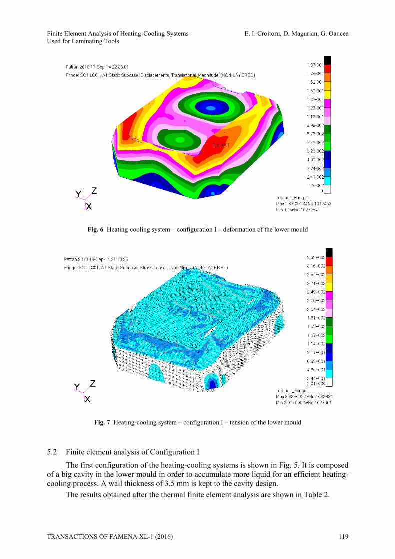
Fig. 6 Heating-cooling system – configuration I – deformation of the lower mould
Fig. 7 Heating-cooling system – configuration I – tension of the lower mould
5.2 Finite element analysis of Configuration I The first configuration of the heating-cooling systems is shown in Fig. 5. It is composed
of a big cavity in the lower mould in order to accumulate more liquid for an efficient heating-cooling process. A wall thickness of 3.5 mm is kept to the cavity design.
The results obtained after the thermal finite element analysis are shown in Table 2.
TRANSACTIONS OF FAMENA XL-1 (2016) 119
E. I. Croitoru, D. Magurian, G. Oancea Finite Element Analysis of Heating-Cooling Systems Used for Laminating Tools
Table 2 Results of the thermal FEA - Configuration I
Part / Result Lower mould Δl [mm] 0.187 σarea [MPa] 24.4 – 69.3
5.3 Finite element analysis of Configuration II To avoid vortex effects, the second system is designed, as presented in Fig. 8. The
designed geometry is a combination of a spiral and a helix. The spiral area is positioned at a constant distance from the active area, taking the resulting geometry shape.
Fig. 8 Heating-cooling system of configuration II
Fig. 9 Heating-cooling system – configuration II - deformation of the lower mould
120 TRANSACTIONS OF FAMENA XL-1 (2016)
Finite Element Analysis of Heating-Cooling Systems E. I. Croitoru, D. Magurian, G. Oancea Used for Laminating Tools
Fig. 10 Heating-cooling system – configuration II - tension of the lower mould
Fig. 11 Heating-cooling system of configuration III
Fig. 12 Heating-cooling system – configuration III - deformation of the lower mould
TRANSACTIONS OF FAMENA XL-1 (2016) 121
E. I. Croitoru, D. Magurian, G. Oancea Finite Element Analysis of Heating-Cooling Systems Used for Laminating Tools
Fig. 13 Heating-cooling system – configuration III - tension of the lower mould
The complete results of the thermal finite element analysis are shown below.
Table 3 Results of thermal FEA - Configuration II
Part / Result Lower mould Δl [mm] 0.140 σarea [MPa] 28.2 – 83.2
5.4 Finite element analysis of Configuration III The third heating-cooling system configuration consists of spiral geometry in three
layers. The first layer is placed 4 mm from the active area keeping the shape geometry. The second and third layers follow at a constant distance (see Fig. 11).
Complete results of the thermal finite element analysis are shown in Table 4.
Table 4 Results of thermal FEA - Configuration III
Part / Result Lower mould Δl [mm] 0.138 σarea [MPa] 28.3 – 56.1
5.5 Finite element analysis of Configuration IV In the case of the fourth system configuration, a combination of two spiral-and-helix
geometries with independent input and output of distilled water is assessed, as presented hereafter.
122 TRANSACTIONS OF FAMENA XL-1 (2016)
Finite Element Analysis of Heating-Cooling Systems E. I. Croitoru, D. Magurian, G. Oancea Used for Laminating Tools
Fig. 14 Heating-cooling system of configuration IV
Fig. 15 Heating-cooling system – configuration IV - deformation of the lower mould
Fig. 16 Heating-cooling system – configuration IV - tension of the lower mould
TRANSACTIONS OF FAMENA XL-1 (2016) 123
E. I. Croitoru, D. Magurian, G. Oancea Finite Element Analysis of Heating-Cooling Systems Used for Laminating Tools
Complete results of the thermal finite element analysis are shown below.
Table 5 Results of thermal FEA - Configuration IV
Part / Result Lower mould Δl [mm] 0.135 σarea [MPa] 0.61 – 28.3
6. Results and analysis
The thermal finite element analysis is done for all configurations presented above to determine the deformations and tensions in the components of each assembly. These results lead to the configuration of the heating-cooling system which represents an optimum from the heat transfer point of view. In this matter, the optimum means to release the energy of the heating agent as fast as possible, glue the leather to the plastic part and return to the initial state.
Complete results of the thermal finite element analysis for all configurations of heating-cooling system are shown in Table 6.
Table 6 Results of thermal FEA
Part / Result Δl [mm] σarea [MPa] Lower mould for Configuration I 0.187 24.4 – 69.3 Lower mould for Configuration II 0.140 28.2 – 83.2 Lower mould for Configuration III 0.138 28.3 – 56.1 Lower mould for Configuration IV 0.135 0.6 – 28.3
From the four heating-cooling system configurations which were modelled and analysed by means of finite element analysis, the optimum structure regarding stress is the final one, where the deformations and tensions are the smallest of all configurations. Thus, the configuration IV is considered to be the optimal one.
Table 7 Results of thermal FEA for configuration IV
Part / Result T [oC] Δl [mm] σarea [MPa] σcircuit [MPa] Configuration IV 60 0.135 0.60 – 28.3 13.8 – 93.5 Configuration IV 65 0.136 0.61 – 28.4 15.5 – 103.0 Configuration IV 70 0.137 0.55 – 28.4 17.2 – 113.0 Configuration IV 75 0.137 0.51 – 28.5 19.0 – 124.0 Configuration IV 80 0.138 0.58 – 28.6 20.8 – 135.0 Configuration IV 85 0.139 0.64 – 29.1 22.5 – 147.0 Configuration IV 90 0.140 0.58 – 29.4 24.0 – 158.0 Configuration IV 95 0.140 0.56 – 29.9 25.4 – 169.0 Configuration IV 100 0.141 0.57 – 30.3 27.0 – 180.0
124 TRANSACTIONS OF FAMENA XL-1 (2016)
Finite Element Analysis of Heating-Cooling Systems E. I. Croitoru, D. Magurian, G. Oancea Used for Laminating Tools
Further investigation has been carried out on configuration IV of the heating-cooling system of the specified laminated tool in order to determine the dependences between the loading parameter, in this case temperature, and the deformations/tensions that occur in the material.
For the selected configuration, the loading parameter (temperature) is modified in order to observe the effect of this change on deformations and tensions.
Complete data used as the input and the obtained results in the thermal finite element analysis are presented in Table 7.
Fig. 17 Heating-cooling system – configuration IV – interdependence between temperature and deformation
Fig. 18 Heating-cooling system – configuration IV – interdependence
between temperature and tension in the area of interest
TRANSACTIONS OF FAMENA XL-1 (2016) 125
E. I. Croitoru, D. Magurian, G. Oancea Finite Element Analysis of Heating-Cooling Systems Used for Laminating Tools
Fig. 19 Heating-cooling system – configuration IV – interdependence between temperature and tension at the circuit edge
Fig. 20 Heating-cooling system – configuration IV - tension at the circuit edge
Deformation as a function of temperature is presented in Fig. 17 and the tension
distribution in the heating–cooling system circuit is shown in Fig. 18 and Fig. 19. The coefficient of determination of these three functions was computed using the following formula [20]:
2
22
)()(
11yyyy
SSTotalSSErrorR
i
ii (14)
This coefficient indicates the percent of variation in the response that is explained by the model; the higher the value of R2 the better the model fits the data used. Thus, with a value of R2 of 0.9811 for deformation and a value of R2 of 0.9993 for tensions at the edge of the circuit, the results of the finite element analysis are highly accurate. The mathematical models of these interdependences are the following:
126 TRANSACTIONS OF FAMENA XL-1 (2016)
Finite Element Analysis of Heating-Cooling Systems E. I. Croitoru, D. Magurian, G. Oancea Used for Laminating Tools
deformation: 126.0*0001.0 Tl ; (15)
tension in the area of interest:
488.35*1942.0*0015.0 2 TTarea ; (16)
tension at the circuit edge:
367.39*19.2 Tcircuit . (17)
Equations (15-17) provide us with a confirmation of the conclusion in section 3. This means that FEA can offer great support in the assessment of such a complex geometry like the one in laminating tools without the limitation imposed by the study of complicated equations. Results obtained from such an analysis can easily be explained and / or applied by using simple equations (15 – 17).
It is useful to mention that the ultimate tensile strength of the lower mould material, Al7075, amounts to 572 MPa. Thus, the part withstands the tensions occurring due to the thermal loading which are presented in Table 7. One example of such tensions at the circuit edge is presented in Fig. 20. With these calculations, it can be concluded that the finite element analysis results are precise and the research can be used in the process of design of laminating tools.
7. Conclusion
This paper deals with the issue of analysing different configurations of heating-cooling systems for laminating tools used in the automotive industry by means of finite element analysis. The analysed heating-cooling systems are: a big cavity in the lower mould which accumulates more liquid, a 3D combination of a spiral and a helix, a 3D spiral geometry with three superposed layers and two 3D spirals and helix geometry with independent input and output of liquid. Based on the data obtained from the performed analyses, one can consider the configuration with minimum deformations and tensions as an optimal design solution. It is the fourth configuration, the two 3D spiral and helix geometry. For this configuration, three mathematical models of deformations and tensions were established as functions of temperature for this configuration.
The results obtained in this research can be used in the design process of new laminating tools with lower moulds which contain a heating-cooling system composed of two 3D spirals and helix geometry with independent input and output of liquid. As this configuration is used as an optimal solution, performance of the laminating tool is improved.
In the future, the obtained mathematical models will be used in the development of an original software system. This software system will be a useful tool in the design and manufacture of laminating tools. Its intended purpose would be the parameterized generation of heating-cooling systems used for different laminating tools in the automotive industry.
Acknowledgement
This paper is supported by the Sectoral Operational Programme for Human Resources Development (SOP HRD), ID134378 financed by the European Social Fund and by the Romanian Government.
TRANSACTIONS OF FAMENA XL-1 (2016) 127
E. I. Croitoru, D. Magurian, G. Oancea Finite Element Analysis of Heating-Cooling Systems Used for Laminating Tools
REFERENCES [1] ***: Technologies for Surfaces of Leather / Artificial Leather. 2014, available at:
http://www.frimo.com/en/products/frimo-technologies/laminating.html, accessed: 28.04.2014. [2] P. W. Klein: Fundamentals of Plastics Thermoforming. Morgan & Claypool Publishers, 2009. [3] E. I. Croitoru, D. Magurian, G. Oancea: Finite element analysis of laminating tools for automotive
interior. Applied Mechanics and Materials, 2014, Vol. 693, pp. 273 – 278. [4] ***: MSC Patran 2010 Quick Reference Guide, Linear Static Analysis User’s Guide. Vol. 1, Rev. 1,
October 5, 2010. [5] ***: MSC Nastran 2010 Quick Reference Guide, Linear Static Analysis User's Guide. Vol. 1, Rev. 1,
October 5, 2010. [6] G. R. Glozer, J. R. Brevick: Laminate Tooling for Injection Moulding. Proceedings of the Institution of
Mechanical Engineers, Part B: Journal of Engineering Manufacture, 1992, Vol. 207, pp. 9 – 14. [7] D. F. Marfilius, R. E. Szalma, R. Johnson: Method of manufacturing an interior automotive component
and components made therefrom. Magna Interior Systems Inc., 2001. [8] M. K. Neitzke: In mold lamination of decorative products. International Automotive Components Group
North America Inc., US7674414 B2, 2010. [9] R. Schulze-Kadelbach, K. Falk: Large-size panel of thermoplastic synthetic resin for automotive vehicle
interior, and process for the production thereof. Konrad Hornschuch Ag, US5514458 A, 1996. [10] S. M. Imfeld, R. H. Brandon, M. J. Kocsis, M. T. Stewart, L. P. Benedict: Thermoplastic Adhesive Films
for Automotive Interior Trim Application. SAE Technical Paper 910521, 1991. [11] J. R. Johnson, D. M. Mercier: Interior automotive laminate with thermoplastic low gloss coating. Avery
Dennison Corporation, US5750234 A, 1998. [12] P. D. Hilton, P. F. Jacobs: Rapid Tooling: Tehnologies and Industrial Applications. Marcel Dekker AG,
2000. [13] A. J. Norwood, P. M. Dickens, R. C. Soar, R. Harris, G. Gibbons, R. Hansell: Analysis of cooling channel
performance. International Journal of Computer Integrated Manufacturing, , 2004, Vol. 17, pp. 669 – 678. [14] D. E. Dimla, M. Camilotto, F. Miani: Design and optimisation of conformal cooling channels in injection
moulding tools. Journal of Materials Processing and Technology, 2005, Vol. 164–165, pp. 1294 – 1300. [15] Z. Shayfull, S. Sharif, A. Mohd Zain, R. Mohd Saad, M. A. Fairuz: Milled Groove Square Shape
Conformal Cooling Channels in Injection Molding Process. Materials and Manufacturing Processes, 2013, Vol. 28, pp. 884 – 891.
[16] J. Liang, H. Narahara, H. Koresawa, H. Suzuki: Verification and evaluation of automatically designed cooling channels for block-laminated molds. International Journal of Advanced Manufacturing and Technology, Vol. 75, 2014, pp. 1751 – 1761.
[17] P. A. Tipler; G. Mosca: Physics for Scientists and Engineers. Worth Publishers, 2008, Vol. 1, pp. 666–670.
[18] W. S. Slaughter: The Linearized Theory of Elasticity, Birkhäuser, 2001. [19] A. Entrekin: Accuracy of MSC/NASTRAN First- and Second-Order Tetrahedral Elements in Solid
Modeling for Stress Analysis. MSC Aerospace Users’ Conference Proceedings, 1999. [20] S. A. Glantz, B. K. Slinker: Primer of Applied Regression and Analysis of Variance, McGraw-Hill, 1990.
Submitted: 17.01.2015 Accepted: 28.01.2016
Emilian-Ionut Croitoru Daniel Magurian Gheorghe Oancea Department of Manufacturing EngineeringTransilvania University of Brasov Mihai Viteazu street, no. 5 Brasov, 500174, Romania [email protected]