FINITE ELEMENT ANALYSIS OF HYBRID ENERGY HARVESTING OF PIEZOELECTRIC AND ELECTROMAGNETIC MUHAMMAD AMMAR FARIS BIN MUHAMMAD YAZID This thesis is submitted as partial fulfilment of the requirements for the award of the Bachelor of Engineering (Hons.) Mechatronics Engineering - (Dual Degree Programme with Karlsruhe University of Applied Sciences, HsKA, Germany) Faculty of Manufacturing Engineering Universiti Malaysia Pahang (UMP) MARCH 2016
Transcript
ii
FINITE ELEMENT ANALYSIS OF HYBRID ENERGY HARVESTING OF
PIEZOELECTRIC AND ELECTROMAGNETIC
MUHAMMAD AMMAR FARIS BIN MUHAMMAD YAZID
This thesis is submitted as partial fulfilment of the requirements for the award of the Bachelor
of Engineering (Hons.) Mechatronics Engineering - (Dual Degree Programme with Karlsruhe
University of Applied Sciences, HsKA, Germany)
Faculty of Manufacturing Engineering
Universiti Malaysia Pahang (UMP)
MARCH 2016
vi
ABSTRACT
Harvesting energy from ambient vibrations is a highly sought after method because of the wide
range of available sources that produce vibration energy applicable from industrial machinery
to human motion application. This report studied the implementation of harvesting energy from
two technologies to form a hybrid energy harvester system. These two technologies involves are
relate to the piezoelectric harvesting energy as well as the electromagnetic harvesting energy. A
finite element model was developed by using the Ansys software with the harmonic analysis
solver to analyze and examine hybrid harvesting energy system. The variance dimension of
geometry on the bimorph piezoelectric cantilever beam is also being implemented in order to
study the performance of the beam relating to the difference perspective of dimension. The
proposed length of the cantilever beam was 16.5mm and 36.5mm with the width of 6.35mm,
12.7mm, and 19.05mm. Both power output generated from the magnet and the piezoelectric is
then combined to form one unit of energy. The result shows the system generate the maximum
power output of 14.85𝜇𝑊 from 100Hz, 4.905𝑚/𝑠2, and 0.6𝑐𝑚3 for resonance frequency,
acceleration, and the volume respectively from the selected sample of the energy harvester
design. The NPD result of 10.29 𝑘𝑔𝑠/𝑚3compared with other literature also can be used in
energy harvesting system for vibration application.
vii
ABSTRAK
Penuaian tenaga daripada getaran ambien merupakan kaedah yang sangat dicari-cari kerana
terdapatnya rangkaian yang luas untuk menghasilkan tenaga getaran. Ia juga boleh dihasilkan
dan digunapakai dalam pelbagai cabang aplikasi bermula daripada jentera-jentera atau mesin
yang terdapat di kawasan perindustrian sehinggalah pengunaan dalam sistem pergerakan tubuh
manusia. Laporan ini mengkaji pelaksanaan tenaga penuaian daripada dua teknologi untuk
menghasilkan satu sistem penuai tenaga hibrid. Implementasi kajian menggunakan kaedah
“model unsur terhingga” (FEA) telah dijalankan dengan menggunakan perisian Ansys sebagai
alat bantuan untuk membantu menyelesaikan analisa harmonik dalam kerangka sistem tenaga
penuaian hibrid. Kedua-dua teknologi yang digabungkan dalam sistem ini adalah berkaitan
dengan teknologi penuaian tenaga daripada piezoelektrik serta elektromagnet. Terdapat pelbagai
variasi dimensi geometri yang dicadangkan pada rasuk julur piezoelektrik bimorph mengikut
beberapa sampel. Perkara ini dilakukan untuk menguji prestasi sistem tenaga penuaian hibrid
mengikut pemboleh ubah dimensi. Kedua-dua pengeluaran kuasa yang dijana daripada magnet
dan piezoelektrik ini kemudiannya digabungkan untuk membentuk satu unit tenaga. Daripada
kajian yang telah dijalankan, sistem hibrid ini telah menghasilkan maksimum pengeluaran kuasa
sebanyak 14.85μW dari 100Hz, 4.905𝑚/𝑠2, dan 0.6𝑐𝑚3 frekuensi resonans, pecutan, dan
isipadu sampel yang terpilih daripada rekaan penuai tenaga. Hasil NPD menunjukkan sebanyak
10.29 𝑘𝑔𝑠/𝑚3 dapat diperoleh daripada sistem ini dan jumlah ini telah dibandingkan dengan
hasil daripada kajian-kajian yang dilakukan daripada penyelidik-penyelidik yang lain. Secara
tuntasnya, sistem penuaian tenaga hibrid ini boleh digunakan dalam sistem penuaian tenaga
khusus untuk aplikasi getaran.
viii
TABLE OF CONTENTS
Page
SUPERVISOR’S DECLARATION ii
STUDENT’S DECLARATION iii
ACKNOWLEDGEMENTS v
ABSTRACT vi
ABSTRAK vii
TABLE OF CONTENTS viii
LIST OF TABLES xi
LIST OF FIGURES xii
LIST OF SYMBOLS xv
CHAPTER 1 INTRODUCTION 1
1.1 Background of Project 1
1.2 Problem Statement 3
1.3 Objectives 3
1.4 Scope of Project 3
CHAPTER 2 LITERATURE REVIEW 4
2.1 Energy 4
2.1.1 Source of Energy 4
2.1.2 Electrical Energy 5
2.1.3 Faraday’s Law 6
2.1.4 Lenz’s Law 8
2.2 Fundamental of Energy Harvesting 9
2.3 Types of Energy Harvesting 10
2.3.1 Photonic 10
ix
2.3.2 Thermal 12
2.3.3 Vibration 13
2.4 Method To Generate Electricity 15
2.4.1 Electromagnetic 15
2.4.2 Piezoelectric 16
2.5 Previous Research 17
2.5.1 Energy Harvesting From Electromagnetic 17
2.5.2 Energy Harvesting From Piezoelectric 18
2.6 Summary 19
CHAPTER 3 METHODOLOGY 20
3.1 Introduction 20
3.2 Proposed Design 20
3.2.1 Design Geometry 21
3.2.2 Materials Properties 23
3.3 Procedure 24
3.4 Design Development And Analysis Tools 25
3.5 Modeling Design 26
3.5.1 Developing The Beam 26
3.6 Simulation Modeling 33
3.7 Calculation of Piezoelectric Power Output 39
3.8 Simulation of Electromagnetic 40
3.9 Calculation of Electromagnetic Power Output 41
3.10 Summary 42
CHAPTER 4 RESULT AND DISCUSSION 43
4.1 Introduction 43
4.2 Piezoelectric: Geometry Properties of the Beams 43
4.3 Piezoelectric: Stress Distribution of the Beam 45
4.4 Piezoelectric: Relationship between Deflection of the Beam and the
Natural Frequency of the System 46
x
4.6 Magnet: Voltage and Power Output 51
4.7 Total Power of the Hybrid Harvesting System 52
4.6 Comparison of Normalized Power Density 53
4.6 Summary 54
CHAPTER 5 CONCLUSION 55
5.1 Introduction 55
5.2 Conclusion 55
5.3 Recommendation for Future Work 56
REFERENCES 57
APPENDICES 60
xi
LIST OF TABLES
Table No. Title Page
3.1 Dimensions of the initial design. 22
3.2 List of dimension for each cantilever beam sample. 22
3.3 Mechanical and electrical properties used in the FEA. 24
3.4 Material property of magnet 41
4.1 Dimensions of the beam sample. 44
xii
LIST OF FIGURES
Figure No. Title Page
1.1 Typical implementation of microstructure device using the
piezoelectric inside the shoe as the power generator
2
1.2 CPU transistor counts for the year 1971-2008. 2
2.1 Two forms of energy, renewable energy and non-renewable energy. 5
2.2 Two kinds of electrical charge. The protons are said to be positive
(+). The electrons are said to be negative (-).
6
2.3 Electromagnetic Induction 7
2.4 Determination of the direction of induced current by the right-hand
rule
9
2.5 Generic sensor node architecture 10
2.6 The difference between Photovoltaic Cell, Module, and Array 11
2.7 The process known as the "Photovoltaic Effect" to produce the
electricity.
11
2.8 The configuration of the thermoelectric generator 13
2.9 Sources of generation of vibrational energy 14
2.10 Comparison of wavelength, frequency and energy for the
electromagnetic spectrum
16
2.11 (a) Normal condition of piezoelectric material, (b) energy
generation under tension, (c) energy generation under compression
17
3.1 Piezo-Electromagnetic design concept 21
3.2 Load and boundary conditions of the simulation setup. 21
3.3 Flowchart of the methodology 25
3.4 Standard plane direction selection use for 2D sketching. 27
3.5 2D sketching view of the rectangle on the front plane. 28
xiii
3.6 The yellow preview shows the extrusion of the rectangle. 29
3.7 The preview shows the complete solid geometry of the rectangle 29
3.8 The 3D document can be saves into different number of format. 30
3.9 The imported part in the assembly working environment. 31
3.10 The mate features used to joint two layers. 32
3.11 The complete assembly of the piezoelectric beam with the mass. 32
3.12 Harmonic response analysis was chosen from the analysis system
box.
34
3.13 Imported geometry in the Workbench ANSYS. 35
3.14 Defining the model properties using the Command (APDL) 36
3.15 Meshing the geometry 37
3.16 The fixed support area is selected at the free end of the cantilever
beam.
38
3.17 Frequency response output is selected to generate solution. 39
3.18 Magnetic model in Ansys Workbench. 41
3.19 Waveform amplifier drives current through the coil at resonance 42
4.1 The difference of volume amount between each sample of
cantilever beam.
44
4.2 The difference of total mass between each sample of cantilever
beam
45
4.3 The difference of von Mises stress between each sample of
cantilever beam.
46
4.4 Contour plot of von Mises stress profile from the Beam F sample. 46
4.5 The difference of deflection amount between each sample of
cantilever beam.
47
4.6 The resonance frequency range obtained for each sample of
cantilever beam.
48
xiv
4.7 The peak value of stress at a frequency response of the cantilever
beam E.
48
4.8 The voltage output generated from the piezoelectric bimorph beam
with the length of 16.5mm
49
4.9 The voltage output generated from the piezoelectric bimorph beam
with the length of 36.5mm.
50
4.10 The power output generated from the piezoelectric bimorph beam
with the length of 16.5mm.
50
4.11 The power output generated from the piezoelectric bimorph beam
with the length of 36.5mm.
51
4.12 Cross section geometry of the total magnetic flux density produced
from the electromagnetic analysis
52
4.13 Electrical potential produced from the electromagnetic analysis 52
xv
LIST OF SYMBOLS
𝐴𝑖𝑛 Input acceleration
b* Strain related to vertical displacement of the beam
c Speed of light
𝐶𝑝 Capacitance of the piezoelectric device
d Piezoelectric strain coefficient
D Electric displacement
E Electric field
f frequency
k Coupling coefficient
P Power
R Load resistance
𝑡𝑐 Thickness of the piezoelectric material
V Voltage
𝑌 Young’s Modulus
ωn Natural frequency of the system
ω Driving frequency
δ Mechanical strain
xvi
𝛷𝐵 Rate of change of magnetic flux
ζ Mechanical damping ratio
𝜀 Total induced EMF
ε Dielectric constant of the piezoelectric material
σ Mechanical stress
xvii
LIST OF ABBREVIATIONS
AC Alternate Current
CAD Computer Aided Drafting
CAE Computer Aided Engineering
DC Direct Current
EH Energy Harvester
EMF Electromagnetic Field
FE Finite Element
MEMS Micro-electromechanical Systems
NdFeB Neodymium Iron Boron
NPD Normalized Power Density
PE Piezoelectric-Electromagnetic
PV Photovoltaic
PZT Piezoelectric Material
VEH Vibrational energy harvesting
1
CHAPTER 1
INTRODUCTION
1.1 BACKGROUND OF PROJECT
The terms of harvesting energy can be referred as the process by which the energy
is derived from the ambient source, captured and being stored. Solar, wind, and thermal
energy are the common ambient energy sources used for energy harvesting. As the
sources of energy are becoming more scarce and expensive, the energy harvesting is
receiving more global interest and is currently a growing field.
In today’s world, energy harvesting plays a crucial role in supplying the energy to
various application such as small wireless autonomous devices. For example, the
Vibrational energy harvesting (VEH) with micro-electromechanical systems (MEMS)
generators based might be able to provide several amount of energy in microwatts of
electrical power. MEMS are micro-electromechanical systems comprising of computers
linked to tiny mechanical and other devices like sensors, valves, gears, and actuators,
embedded in semiconductor chips based on silicon as shown in Figure 1.1.
With the rapid development of microelectronic devices in military, medical, and
civil applications, a traditional bulky battery can no longer meet the needs of advanced
sensing technology due to its limited service life and difficulty in replacement. Hence,
much attention should be place for research and development in sustaining the power
requirement for autonomous wireless and portable devices. Energy harvesting has
2
becoming one of the best option for the implementation in order to fulfil the condition as
stated. Currently, the technological advancements have made the energy harvesting
become much more deployable since the devices introduced in commercial nowadays
were using the ultra-low power components. Figure 1.2 shows the number of transistors
per chip doubling every two years.
Figure 1.1: Typical implementation of microstructure device using the piezoelectric
inside the shoe as the power generator
Source: Ville Kaajakari (2010)
Figure 1.2: CPU transistor counts for the year 1971-2008.
Source: Wgsimon (2008)
3
1.2 PROBLEM STATEMENT
Vibration energy are generated from any perceivable activity and usually seen as
the noise. However, if the energy were scavenged at the certain level of resonance
frequency, it can produce the power output in which can be implemented to any useful
application especially in the milliwatt power levels application as such in the MEMS
technology. Several studies has been conducted by the scholars regarding on the energy
harvesting system by using the electromagnetic and piezoelectric transduction. These
research employ these two technologies to develop the hybrid harvesting energy systems
in order to capture the ambient source of energy from the vibration.
1.3 OBJECTIVES
This research is made to fulfill objectives:
i. Model hybrid energy harvesting system of piezoelectric and
electromagnetic using harmonic analysis in Ansys software.
ii. Analyze hybrid energy harvesting system with different width and length
of bimorph piezoelectric beam to produce power from the mechanical
strain
1.4 SCOPE OF PROJECT
To fulfill above, the scope of project study are:
i. Model hybrid harvesting energy using the piezoelectric and magnet material
ii. Bimorph piezoelectric cantilever beam is used with dimension as follows:
a. Width : 6.35mm, 12.7mm, 19.05mm
b. Length : 16.5mm, 36.5mm
iii. Simulation using the harmonic analysis in Ansys software to produce the
deflection of the beam and voltage output of the piezoelectric bimorph beam.
iv. The project required to be accomplished within the 6 month of period based
on the Gantt chart schedule proposed (Appendixes A).
4
CHAPTER 2
LITERATURE REVIEW
2.1 ENERGY
By definition, energy is the capacity of a physical system to perform work (Rouse,
2005). Energy exists in several forms such as heat, kinetic or mechanical energy, light,
potential energy, electrical, or other forms. According to the law of conservation of
energy, the total energy of a system remains constant, though energy may transform into
another form. The SI unit of energy is the joule (J) or newton-meter (N.m) in which it is
also the SI unit of work. In electrical circuits, energy is a measure of power expended
over time. In this sense, one joule (1 J) is equivalent to one watt (1 W) dissipated or
radiated for one second (1 s). A common unit of energy in electric utilities is the kilowatt-
hour (kWh), which is the equivalent of one kilowatt (kW) dissipated or expended for one
hour (1 h).
2.1.1 Source of Energy
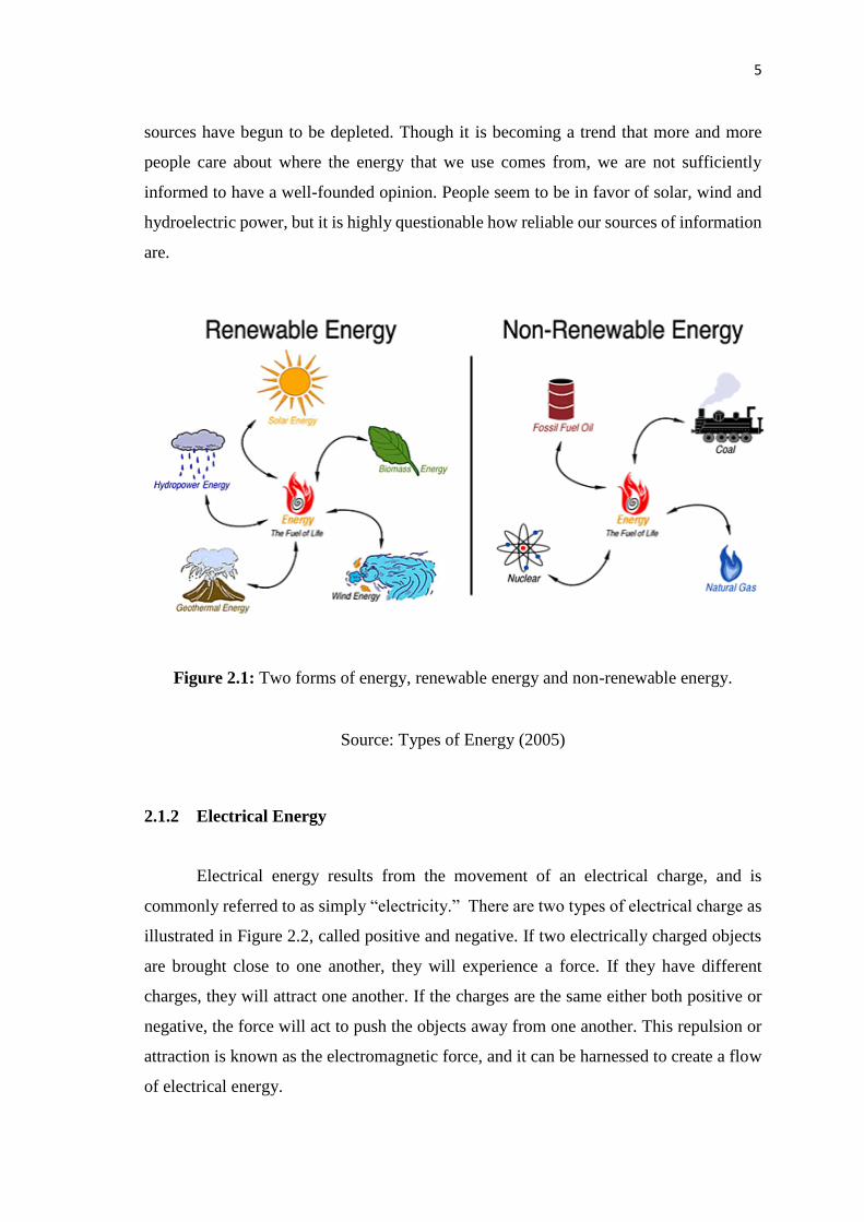
Figure 2.1 shows the energy sources can be classified into two types,
nonrenewable energy and renewable energy. Nonrenewable resources, such as fossil fuels
and nuclear material, are removed from the earth and can be depleted. These resources
have been the most used type of energy in the modern era. Renewable resources, such as
wind, water, solar, and geothermal, come from sources that regenerate as fast as they are
consumed and are continuously available. Some, such as biofuel produced from food
crops and other plants, are replenished every growing season. In the early part of the
twenty-first century, renewable sources have become more popular as nonrenewable
5
sources have begun to be depleted. Though it is becoming a trend that more and more
people care about where the energy that we use comes from, we are not sufficiently
informed to have a well-founded opinion. People seem to be in favor of solar, wind and
hydroelectric power, but it is highly questionable how reliable our sources of information
are.
Figure 2.1: Two forms of energy, renewable energy and non-renewable energy.
Source: Types of Energy (2005)
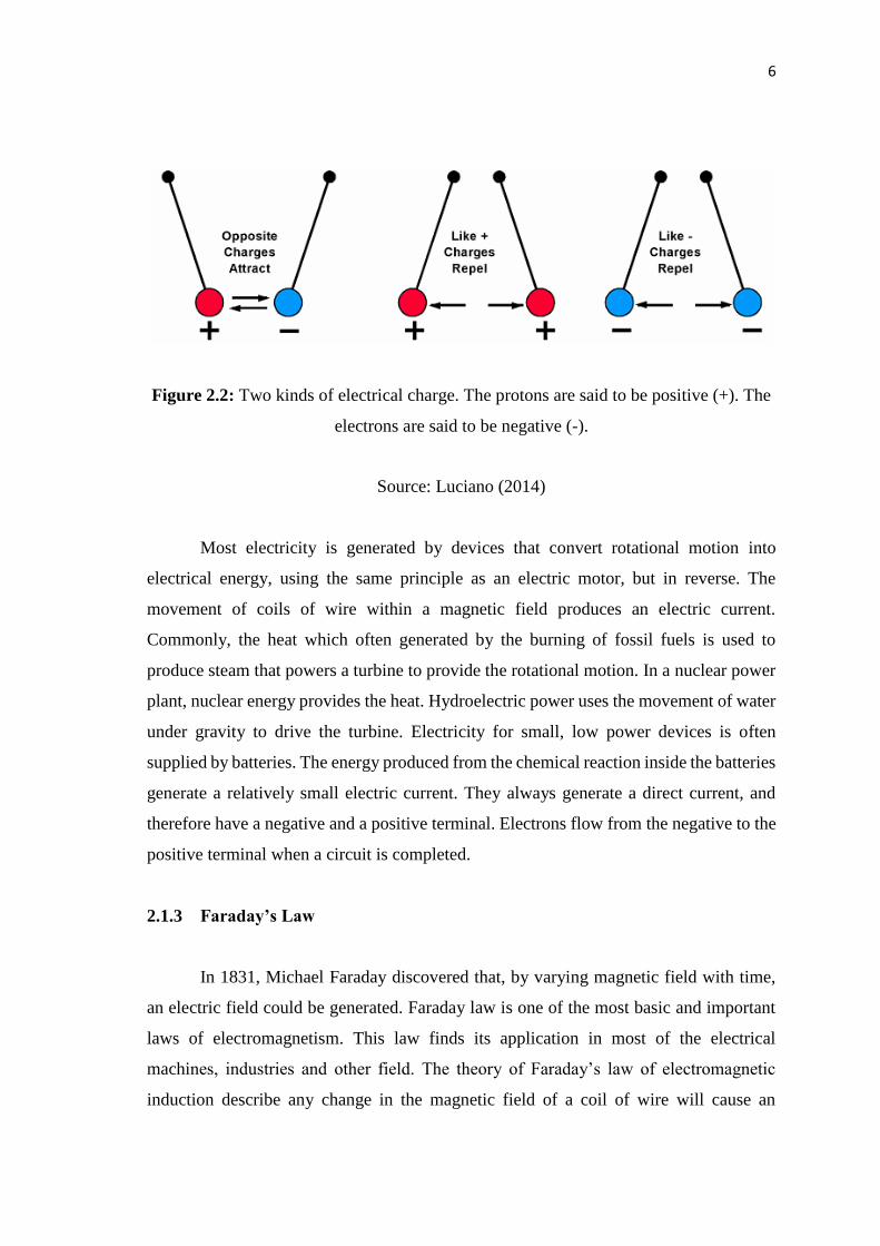
2.1.2 Electrical Energy
Electrical energy results from the movement of an electrical charge, and is
commonly referred to as simply “electricity.” There are two types of electrical charge as
illustrated in Figure 2.2, called positive and negative. If two electrically charged objects
are brought close to one another, they will experience a force. If they have different
charges, they will attract one another. If the charges are the same either both positive or
negative, the force will act to push the objects away from one another. This repulsion or
attraction is known as the electromagnetic force, and it can be harnessed to create a flow
of electrical energy.
6
Figure 2.2: Two kinds of electrical charge. The protons are said to be positive (+). The
electrons are said to be negative (-).
Source: Luciano (2014)
Most electricity is generated by devices that convert rotational motion into
electrical energy, using the same principle as an electric motor, but in reverse. The
movement of coils of wire within a magnetic field produces an electric current.
Commonly, the heat which often generated by the burning of fossil fuels is used to
produce steam that powers a turbine to provide the rotational motion. In a nuclear power
plant, nuclear energy provides the heat. Hydroelectric power uses the movement of water
under gravity to drive the turbine. Electricity for small, low power devices is often
supplied by batteries. The energy produced from the chemical reaction inside the batteries
generate a relatively small electric current. They always generate a direct current, and
therefore have a negative and a positive terminal. Electrons flow from the negative to the
positive terminal when a circuit is completed.
2.1.3 Faraday’s Law
In 1831, Michael Faraday discovered that, by varying magnetic field with time,
an electric field could be generated. Faraday law is one of the most basic and important
laws of electromagnetism. This law finds its application in most of the electrical
machines, industries and other field. The theory of Faraday’s law of electromagnetic
induction describe any change in the magnetic field of a coil of wire will cause an
7
electromagnetic force (EMF) to be induced in the coil. This EMF induced is called
induced EMF and if the conductor circuit is closed, the current will also circulate through
the circuit and this current is called induced current. Figure 2.3 illustrates the phenomenon
known as electromagnetic induction.
Figure 2.3: Electromagnetic Induction
Source: Liao (2004)
Method to change the magnetic field can be done by doing as follows:
1. Moving a magnet towards or away from the coil
2. Moving the coil into or out of the magnetic field
3. Changing the area of a coil placed in the magnetic field
4. Rotating the coil relative to the magnet
Faraday’s law of induction may be stated as follows:
The induced EMF ε in a coil is proportional to the negative of the rate of change
of magnetic flux 𝛷𝐵:
𝜀 =𝑑Φ𝐵
𝑑𝑡 (2.1)
8
For a coil that consists of N loops, the total induced EMF would be N times as
large:
𝜀 =𝑁𝑑Φ𝐵
𝑑𝑡 (2.2)
2.1.4 Lenz’s Law
Lenz's law is a common way of understanding how electromagnetic circuits obey
Newton's third law and the conservation of energy. Lenz's law is named after Heinrich
Lenz, and describe the law as if an induced current flows, its direction is always such that
it will oppose the change which produced it (Liao, 2004). Lenz's law is shown with the
negative sign in Faraday's law of induction which indicates that the induced voltage ℰ and
the change in magnetic flux 𝛷𝐵 have opposite signs as shown in the Eq. (2.3).
𝜀 =−𝑁𝑑Φ𝐵
𝑑𝑡 (2.3)
The minus sign in the equation is important as it means that the EMF creates a
current I and magnetic field B that oppose the change in flux 𝛷𝐵. The direction of induced
current can be determined by using the right-hand rule (Lenz Law of Electromagnetic
Induction, 2011). If the fingers of the right hand are placed around the wire so that the
thumb points in the direction of current flow, then the curling of fingers will show the
direction of the magnetic field produced by the wire as shown in Figure 2.4.
9
Figure 2.4: Determination of the direction of induced current by the right-hand rule
Source: Lenz Law of Electromagnetic (2011)
2.2 FUNDAMENTAL OF ENERGY HARVESTING
The term "energy harvesting" refers to the generation of energy from sources such
as ambient temperature, vibration or air flow. A typical energy harvesting system starts
with an energy collector or transducer device and depends on the type of energy one is
trying to convert. These are typically solar or photovoltaic cells for light energy,
piezoelectric for pressure, kinetic for movement, inductive for rotational or motion,
thermoelectric for heat or temperature differential, and electromagnetic. The energy
harvesting system is quiet significant as it has the potential to replace the batteries for
small, low power electronic devices. Figure 2.5 illustrate the key components of a simple
energy harvesting system to convert and store the ambient energy into electrical energy.
The stored electrical energy can then be used by various sensor nodes for applications
such as sensing, actuating, or sending wireless signals.
10
Ambient
Energy
Energy Harvesting
Device
Power
Management Energy Storage
Sensor Actuator Communication
Figure 2.5: Generic sensor node architecture
Source: Berder (2015)
2.3 TYPES OF ENERGY HARVESTING
It is important to note, that all energy sources are virtually unlimited and can be
harvest from various sources. The most common types of energy harvesting are photonic,
thermal, and vibrational.
2.3.1 Photonic
Common photonic harvesters rely on solar energy drawn with the use of
photovoltaics. Solar cell is the basic component for harvesting the sunlight using solar
photovoltaics and commonly made from semiconductors as shown in the Figure 2.6.
11
Figure 2.7 shows when a solar cell is exposed to sunlight, the photons (sunlight) strike
and ionize the semi-conductor material causing its outer electron to break free of the
atomic bonds. Due to the semiconductor’s structure, the electrons are force to move in
one direction, creating a flow of electrical current.
Figure 2.6: The difference between Photovoltaic Cell, Module, and Array
Source: Solar PV Cell Module Array (2014)
Figure 2.7: The process known as the "Photovoltaic Effect" to produce the electricity.
Source: Lambardo (2014)
According to Kwang (2014), solar cells are not 100% efficient because some
spectrums of the sunlight are being reflected, some are too weak to create electricity
(infrared spectrum) and some create heat energy instead of electricity (ultraviolet
spectrum) Susceptibility to pollutants such as dust that blocks light from the cells may
further impede their efficiency. The fragility of photovoltaic devices is still yet another