FINITE ELEMENT MODELING OF LAMINATED COMPOSITE PLATES WITH LOCALLY DELAMINATED INTERFACE SUBJECTED TO IMPACT LOADING SADDAM HUSSEIN ALI A project report submitted in fulfilment of the requirements for the award of the degree of Master of Engineering(Civil-Structure) Faculty of Civil Engineering Universiti Teknologi Malaysia June 2013
Transcript
FINITE ELEMENT MODELING OF LAMINATED COMPOSITE PLATES WITH
LOCALLY DELAMINATED INTERFACE SUBJECTED TO IMPACT LOADING
SADDAM HUSSEIN ALI
A project report submitted in fulfilment of the
requirements for the award of the degree of
Master of Engineering(Civil-Structure)
Faculty of Civil Engineering
Universiti Teknologi Malaysia
June 2013
iii
This project report is dedicated to my beloved parents.
iv
ACKNOWLEDGEMENT
First and foremost, I would like to express my thanks to Allah who is the one
that helped me and guided me finish this study on time. Second, I would like then to
express my sincere appreciation to my supervisor of this final year project, Dr.
Ahmad Kueh Beng Hong for his continuous guidance, professional advices, support,
motivation, and encouragement to complete this study.
Also, I would like to extend my thanks to my colleagues and friends,
especially Nadera Najib, Mohamud Abdilrahman, and Mohmed Saakhee for their
continuous support and help. Moreover, I would like to express my gratitude to
Universiti Teknologi Malaysia for the facilities and opportunities given to me to
pursue this study.
Last but not least, I would like to thank my parents and family for their
patience, support, prayers, and encouragement during this study.
v
ABSTRACT
This project report presents the finite element formulation for the
investigation of the effects of interface imperfection on the impact behavior of a
laminated composite plate. The interface condition between the laminas plays a very
important role in the determination of the behavior of the composite laminates. If the
bonding is imperfect, it has high possibility to delaminate progressively. Most of the
previous studies on laminated composites were carried out adopting the assumption
that the laminas are perfectly bonded. However, the existence of a perfect interfacial
bond in a real laminated composite seems to be impossible. Therefore, this study
aims to investigate the effect of localized interface imperfection on the behavior of a
laminated composite plate when subjected to low velocity impact loading for various
fiber orientations. A thin, flat, rectangular laminated plate with two layers of E-
glass/Epoxy transversely isotropic lamina and an orthotropic interface layer between
them are considered in this study. The interface is modeled as a layer of zero
thickness and zero mass, and the imperfection factor is applied locally to the
interface. By using MATLAB, the stiffness matrix, mass matrix, and the impact
force vector are formulated and programmed in order to obtain the deformation of
the plate. The results show that as the separation of fiber orientation between the two
laminas increases, both central deflection and energy absorption increase. The
increase of delamination area leads to plate’s damage due to the increase in the
absorbed energy, resulting in higher deformation.
vi
ABSTRAK
Laporan projek ini membentangkan rumusan unsur terhingga bagi menyiasat
kesan ketidaksempurnaan antaramuka pada tingkah laku impak plat komposit
berlapis. Keadaan antaramuka lamina memainkan peranan yang amat penting dalam
menentukan tingkah laku komposit berlapis. Jika ikatan tidak sempurna, ia
mempunyai kemungkinan yang tinggi untuk berpisah secara progresif. Kebanyakan
kajian terdahulu mengenai komposit berlapis telah dijalankan dengan menggunakan
andaian bahawa lamina adalah terikat dengan sempurna. Walaubagaimanapun,
kewujudan ikatan antaramuka yang sempurna dalam komposit berlapis sebenar
adalah mustahil. Oleh itu, kajian ini bertujuan untuk mengkaji kesan
ketidaksempurnaan setempat antaramuka pada kelakuan plat komposit berlapis
apabila dikenakan beban impak halaju rendah untuk pelbagai orientasi serat. Plat
berlapis segiempat nipis dan rata dengan dua lapisan isotropi melintang E-
kaca/epoksi dan lapisan antaramuka ortotropik telah dipertimbangkan dalam kajian
ini. Antaramuka telah dimodelkan sebagai lapisan ketebalan sifar dan berjisim sifar,
dan faktor ketidaksempurnaan telah dikenakan secara setempat kepada antaramuka.
Dengan menggunakan MATLAB, matriks kekukuhan, matriks jisim, dan vektor daya
impak telah dirumus dan diprogramkan untuk mendapatkan ubah bentuk plat.
Keputusan menunjukkan bahawa apabila pemisahan orientasi gentian antara kedua-
dua lamina meningkat, kedua-dua pesongan pusat dan penyerapan tenaga juga
meningkat. Peningkatan kawasan pemisahan membawa kepada kerosakan plat yang
disebabkan oleh peningkatan dalam tenaga yang diserap, dengan akibat ubah bentuk
yang lebih tinggi.
vii
TABLE OF CONTENTS
CHAPTER TITLE PAGE
DECLARATION ii
DEDECATION iii
ACKNOWLEGEMENT iv
ABSTRACT v
ABSTRAK vi
TABLE OF CONTENTS vii
LIST OF TABLES x
LIST OF FIGURES xi
LIST OF SYMBOLS xvi
1 INTRODUCTION 1
1.1 Background of Study 1
1.2 Problem Statement 4
1.3 Objective of the Study 5
1.4 Scope of the Study 5
1.5 Significance of the Study 6
2 LITERATURE REVIEW 8
2.1 General 8
2.2 Laminated Composite Materials 8
2.3 Applications of Laminated Composite Materials in Civil
Engineering. 10
viii
2.4 Laminated Composite Plates 12
2.5 The Behavior of Laminated Composite Plates Subjected to
Impact load 12
2.6 Factors Affecting the Behavior of Composite materials
under Impact load 17
2.6.1 The Laminate Properties Effect 18
2.6.2 Impactor Geometry 24
2.7 Previous Studies on the Interface Layer 26
3 METHODOLOGY 30
3.1 Introduction 30
3.2 Stiffness of the Lamina 32
3.3 Stiffness of the Interface 41
3.4 Element Stiffness Matrix of the Laminate 48
3.5 Global Stiffness Matrix of the Laminate 50
3.6 Computation of the Laminate Mass Matrix 53
3.7 Boundary Conditions 54
3.8 An Overview on the MATLAB Coding for this Study 55
4 RESULTS AND DISCUSSION 61
4.1 Introduction 61
4.2 Convergence Study 61
4.3 Verification of Study 63
4.4 The Effects of Fiber Orientation 64
4.4.1 Central Displacement 65
4.4.2 Relationship between Area of Delamination and
Maximum Central Displacement 68
4.4.3 Force-Displacement Relation of Various Laminates
Progressive Delamination 70
ix
4.5 Simulation of the Damage Behavior due to Blasting Studied
by Naik et al. (2006) 73
4.5.1 Central Displacement 75
4.5.2 The Relationship between Fiber Orientation and
Energy 79
5 CONCLUSIONS AND RECOMMENDATIONS 82
5.1 Conclusion 82
5.2 Recommendations 83
REFERENCES 85-90
Appendices A – E
x
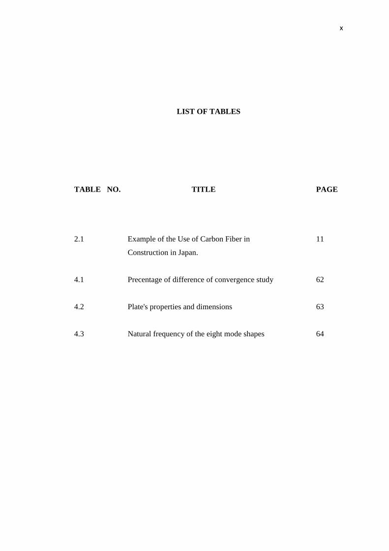
LIST OF TABLES
TABLE NO.
TITLE PAGE
2.1
4.1
4.2
4.3
Example of the Use of Carbon Fiber in
Construction in Japan.
Precentage of difference of convergence study
Plate's properties and dimensions
Natural frequency of the eight mode shapes
11
62
63
64
v
LIST OF FIGURES
FIGURE NO. TITLE PAGE
1.1 Types of Fiber reinforced Composite
materials.
2
1.2 Sketch of the Interface 3
2.1 Use of CFRC panels in the Kita Kyusho
Prince Hotel
11
2.2 The effects of stacking sequence in
laminated composite plates.
13
2.3 Deformed shape of the laminated
composite folded plate under the impact
load.
14
2.4 Falling weight impact machine. 15
2.5 Pendulum impact test system 16
2.6 The gas-gun machine. 16
2.7 Delamination areas in both thick and thin
laminates.
19
2.8 Compression-after-impact strength in
both thick and thin laminates.
19
vi
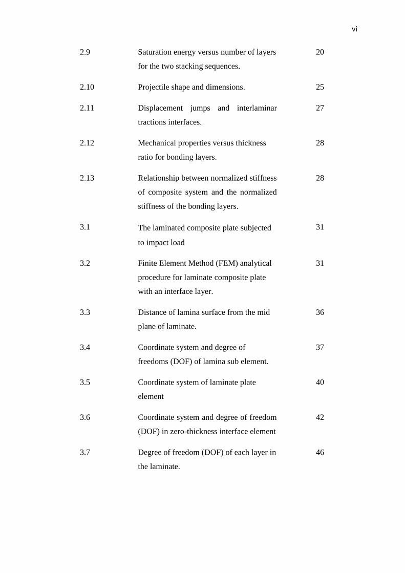
2.9 Saturation energy versus number of layers
for the two stacking sequences.
20
2.10 Projectile shape and dimensions. 25
2.11 Displacement jumps and interlaminar
tractions interfaces.
27
2.12 Mechanical properties versus thickness
ratio for bonding layers.
28
2.13 Relationship between normalized stiffness
of composite system and the normalized
stiffness of the bonding layers.
28
3.1 The laminated composite plate subjected
to impact load
31
3.2 Finite Element Method (FEM) analytical
procedure for laminate composite plate
with an interface layer.
31
3.3 Distance of lamina surface from the mid
plane of laminate.
36
3.4 Coordinate system and degree of
freedoms (DOF) of lamina sub element.
37
3.5 Coordinate system of laminate plate
element
40
3.6 Coordinate system and degree of freedom
(DOF) in zero-thickness interface element
42
3.7 Degree of freedom (DOF) of each layer in
the laminate.
46
xiii
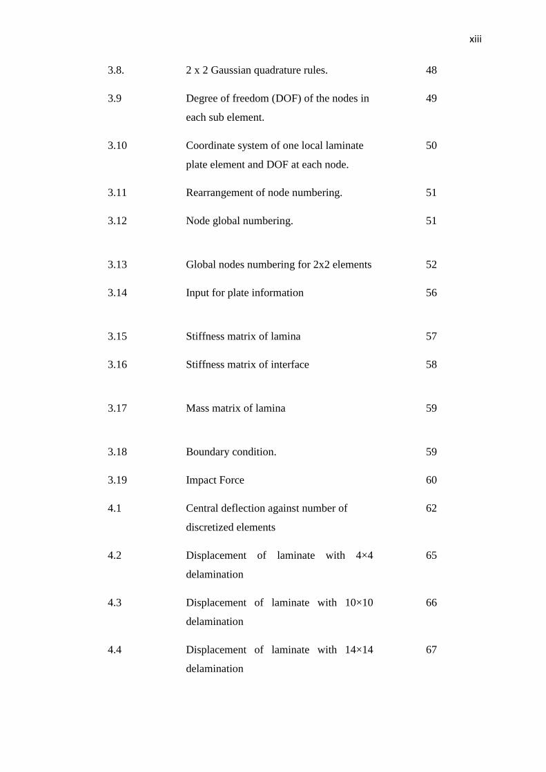
3.8. 2 x 2 Gaussian quadrature rules. 48
3.9 Degree of freedom (DOF) of the nodes in
each sub element.
49
3.10 Coordinate system of one local laminate
plate element and DOF at each node.
50
3.11 Rearrangement of node numbering. 51
3.12 Node global numbering. 51
3.13 Global nodes numbering for 2x2 elements 52
3.14 Input for plate information
56
3.15 Stiffness matrix of lamina
57
3.16 Stiffness matrix of interface
58
3.17 Mass matrix of lamina
59
3.18 Boundary condition. 59
3.19 Impact Force 60
4.1 Central deflection against number of
discretized elements
62
4.2 Displacement of laminate with 4×4
delamination
65
4.3 Displacement of laminate with 10×10
delamination
66
4.4 Displacement of laminate with 14×14
delamination
67
xiv
4.5 Relationship between area of
delamination and maximum displacement
for [0/0] laminate
68
4.6 Relationship between area of
delamination and maximum displacement
for [30/0] laminate
69
4.7 Relationship between area of
delamination and maximum displacement
for [50/0] laminate
69
4.8 Relationship between area of
delamination and maximum displacement
for [90/0] laminate
70
4.9 Force-displacement curve for [0/0]
laminate
71
4.10 Force-displacement curve for [30/0]
laminate
72
4.11 Force-displacement curve for [50/0]
laminate
72
4.12 Force-displacement curve for [90/0]
laminate
73
4.13 Naik et al. (2006) delamination behavior
74
4.14 Simulated delamination based on that of
Naik et al. (2006)
74
4.15 Displacement of laminate with [0/0]
orientation
76
4.16 Displacement of laminate with [30/0]
orientation
77
xv
4.17 Displacement of laminate with [50/0]
orientation
78
4.18 Displacement of laminate with [90/0]
orientation
79
4.19 Force-displacement curve for [0/0]
laminate
80
4.20 Force-displacement curve for [30/0]
laminate
80
4.21 Force-displacement curve for [50/0]
laminate.
81
4.22 Force-displacement curve for [90/0]
laminate
81
xvi
LIST OF SYMBOLS
Vf, Vm - Volume fraction of fiber and matrix respectively
Ef, Em - Young Modulus of fiber and matrix respectively
G12f, Gm - Shear modulus of fiber and matrix respectively
v12f, vm - Poisson’s ratio of fiber and matrix respectively
E1 - Longitudinal Young’s modulus
E2 - Transverse Young’s modulus
G12 - In-plane shear modulus
υ12 - Poisson’s ratio
ξ - Measure of fiber reinforcement of the composite that
depends on the fiber geometry, packing geometry, and
loading conditions. The value of ξ is taken as 2 for E2
calculation while 1 for G12 calculation.
Qij - Lamina stiffness matrix
Qij - Transformed stiffness matrix
N - In-plane force
M - In-plane moment
є0 - Mid-plane strain
xvii
κ - Mid-plane curvature
Aij, Bij, Dij - Laminate extensional stiffness, laminate-coupling
stiffness, and laminate-bending stiffness respectively
u, v, w - Displacement in x, y, z direction respectively
Øx, Øy - Rotation about the x, y direction respectively
Ni, No - Shape function for in-plane and out-of-plane degree of
freedom respectively
[B] - Element strain matrix
[K] - Element stiffness matrix
F - Force
q - Transversely distributed load
dlower - Interpolated displacement of node at lower surface of
the zero-thickness element
dupper - Interpolated displacement of node at upper surface of
the zero-thickness element
N - Lagrange shape function for zero-thickness element
lwd^
- Nodal displacement of node at lower surface of the zero-
thickness element
upd^
- Nodal displacement of node at upper surface of the zero-
thickness element
- Stress
- Strain
D - Constitutive matrix
h - Thickness of interface element
J - Jacobian matrix
xviii
ξ , η - Coordinate sysyem in Gauss quadrature rule
wi , wj - Weight of ith
and jth
Gauss point
f(ξi, ηj) - Function of ith
and jth
Gauss point
CHAPTER 1
INTRODUCTION
1.1 Background of the Study
Composite materials were introduced to several fields such as civil
engineering, aerospace engineering and transportation industry a few decades ago.
Composite materials are generally formed by combining two or more different
materials with different physical and chemical properties in a microscopic scale. The
combination of these materials produces a superior material that has all the properties
of the combined materials. Thus, a composite material can provide an easy approach
to design the right combination of fiber reinforcement and matrix material which
meets the desired specifications.
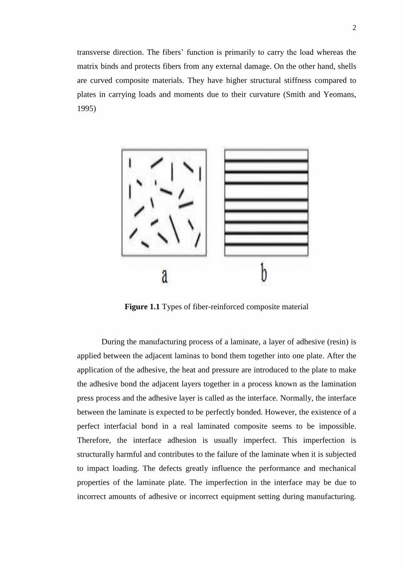
As a matter of fact, there are two types of fiber reinforced composite
materials as shown in Figure 1.1. The first type (Figure 1.1 (a)) is known as short
fiber-reinforced composite. This type is normally used in compression and sheet
moulding operations. The second type is referred to as continuous fiber-reinforced
composite and it is shown in Figure 1.1 (b). It is formed of a layered or laminated
structure. The applications of these fiber reinforced composites are usually used in
the form of plates and shells. Composite plates are always organized in a flat
laminate structure. Each layer of lamina contains an arrangement of unidirectional
fibers embedded within a thin layer of polymer matrix material. Since a single layer
of lamina has a very poor response to transverse tensile stress, each layer of lamina is
stacked together with another layer in order to eliminate the weakness in the
2
transverse direction. The fibers’ function is primarily to carry the load whereas the
matrix binds and protects fibers from any external damage. On the other hand, shells
are curved composite materials. They have higher structural stiffness compared to
plates in carrying loads and moments due to their curvature (Smith and Yeomans,
1995)
Figure 1.1 Types of fiber-reinforced composite material
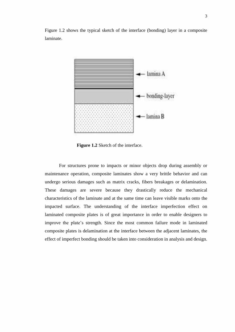
During the manufacturing process of a laminate, a layer of adhesive (resin) is
applied between the adjacent laminas to bond them together into one plate. After the
application of the adhesive, the heat and pressure are introduced to the plate to make
the adhesive bond the adjacent layers together in a process known as the lamination
press process and the adhesive layer is called as the interface. Normally, the interface
between the laminate is expected to be perfectly bonded. However, the existence of a
perfect interfacial bond in a real laminated composite seems to be impossible.
Therefore, the interface adhesion is usually imperfect. This imperfection is
structurally harmful and contributes to the failure of the laminate when it is subjected
to impact loading. The defects greatly influence the performance and mechanical
properties of the laminate plate. The imperfection in the interface may be due to
incorrect amounts of adhesive or incorrect equipment setting during manufacturing.
3
Figure 1.2 shows the typical sketch of the interface (bonding) layer in a composite
laminate.
Figure 1.2 Sketch of the interface.
For structures prone to impacts or minor objects drop during assembly or
maintenance operation, composite laminates show a very brittle behavior and can
undergo serious damages such as matrix cracks, fibers breakages or delamination.
These damages are severe because they drastically reduce the mechanical
characteristics of the laminate and at the same time can leave visible marks onto the
impacted surface. The understanding of the interface imperfection effect on
laminated composite plates is of great importance in order to enable designers to
improve the plate’s strength. Since the most common failure mode in laminated
composite plates is delamination at the interface between the adjacent laminates, the
effect of imperfect bonding should be taken into consideration in analysis and design.
4
1.2 Problem Statement
For composite materials, the interface condition between the laminate plays a
very important role in the determination of the behavior of the composite laminates.
Most of the previous studies on laminated composite were carried out by adopting
the assumption that the laminas were perfectly bonded together. However, some
researchers have been studying the behavior of composite laminates with
interlaminar imperfections.
In most cases, imperfect bonding results in delamination. Delamination is
characterized as an insidious separation developed between laminas without being
seen on the surface. However, it is possible to detect delamination in the composite
material by using advanced techniques such as ultrasonic testing method (Collins,
2009).
It has been proven that the shape of a flat laminated plate subjected to a small
impact load in the transverse direction remains flat and in a state of equilibrium. As
the applied load gradually increases, small initial discontinuity starts to propagate
within the interface between adjacent laminates and results in a significant area of
delamination at the interface. When the magnitude of the impact load reaches
maximum, the configuration of the plate becomes unstable and the laminate starts to
fail (Yousefi et al, 2007).
As mentioned previously, most of the researches done so far are based on the
assumption that the interface of the composite plate is perfectly bonded. Currently,
there exists only a few studies that handle local interface imperfection problem. In
addition, the consideration is either at one location or total separation. Therefore, it
would be of great importance to study the behavior of the composite plate with local
imperfect interface subjected to impact loads.
5
1.3 Objective of the Study
The objectives of the study are:
1. To study the behavior of the laminated composite plates with a localized
delaminated interface when subjected to impact load for various fiber
orientations by means of finite element model.
2. To simulate the response due to the damage of the laminated composite plates
when impacted as that of Naik’s et al (2006).
1.4 Scope of the Study
The study is restricted to a rectangular laminate plate. The laminate plate is
considered to be thin and flat. It consists of two layers of lamina with equal thickness
and an interface layer between them. Each lamina is formed by unidirectional fibers
of E-glass and the matrix material is Epoxy (3501-6) with a volume fraction of 0.4.
The top layer of the lamina comprises fiber that varies in orientation from 0° to 90°
and the bottom layer of lamina comprises 0° fiber direction.
In this study, the lamina is considered as a transversely isotropic solid
material. By using a finite element method, the plate is modeled as a combination of
two laminas with the same boundary condition and thickness using Kirchoff’s
Classical Laminate Theory. Each node of the plate has five degrees of freedom,
which include displacement in x-direction (u), displacement in y-direction (v),
displacement in z-direction (w), rotation about y-direction (Øx) and rotation about x-
direction (Øy).
The interface layer between the two laminas is modeled as an orthotropic
material with zero normal stresses in x and y-directions (σx = 0 and σy = 0) and zero
in-plane shear stress in x-y plane (τxy = 0). The interface layer is modeled using
quadrilateral zero-thickness solid element with 8 nodes. Each node only considers
6
three degrees of freedom including displacement in x-direction (u), displacement in
y-direction (v), and displacement in z-direction (w). The stiffness matrices of the
laminas and interface element are computed using 2 by 2 Gauss quadrature rule. The
study only considers the impact of low velocity applied at the center of the plate with
fully clamped boundaries at all edges. In addition, this study does not take into
consideration the damping effect of the system.
1.5 Significance of the Study
For the last few decades, the application of laminated composite materials
such as plates and shells has been a point of interest in the industry of construction.
The reason behind that is the variety of properties possessed by laminates due to the
fact that they consist of different laminas and they offer mechanical properties that
depend on the fiber orientation. A lot of researches and studies have been
investigating the properties, behavior, strengths, and weaknesses of these laminated
composite materials resulting in tremendous advances in this field. However, there is
still a lot to investigate about these materials in order to optimize their usage in the
construction industry. One of the fields that still needs to be studied deeply is the
behavior of the laminated composite plates with local imperfect interface layer
subjected to impact loading. Generally, the composites are used in the form of