46
Fire Service Summary Report: Study of Residential Attic Fire Mitigation Tactics and Exterior Fire Spread Hazards on Firefighter Safety

Fire Service Summary Report: Study of Residential Attic Fire Mitigation Tactics and Exterior Fire Spread Hazards on Firefighter Safety


Forward
This document is a subset of the full technical report titled, “Study of Residential Attic Fire Mitigation
Tactics and Exterior Fire Spread Hazards on Fire Fighter Safety,” that can be downloaded at
www.ULfirefightersafety.com. There is no additional information provided in this document rather it
includes introductory material, a summary of the experimental setup, fire service tactical considerations
and summary of the full report. Please refer to the full report for more detail and discussion of the
results.
1. Introduction
Research Study Purpose
The purpose of this study is to increase firefighter safety by providing the fire service with
scientific knowledge on the dynamics of attic and exterior fires and the influence of coordinated
fire mitigation tactics from full-scale fire testing in realistic residential structures.
1.1. Background
Attic fires pose many hazards for the fire service. When a fire occurs in an attic, it is common it
goes unnoticed/reported until smoke or flames are visible from the outside of the structure.
Because they take longer to detect, attic fires are more dangerous for firefighters and residents.
In a fire situation, the attic ventilation system, which is designed to reduce moisture
accumulation by drawing fresh air low from the eaves and exhausting moisture laden warm air
near the peak, create an optimal fire growth and spread situation by supplying oxygen to the fire
and exhausting hot gases. An estimated 10,000 residential attic fires are reported to U.S. fire
departments each year and cause an estimated 30 civilian deaths, 125 civilian injuries and $477
million in property loss1.
The location of the attic creates several difficulties for the fire service. Firefighters must decide
whether to fight the fire from inside the structure, from the outside or a combination of the two.
This the decision is complicated by the constant hazard of ceiling collapse, which has the
potential to rapidly deteriorate conditions in the living spaces. A piece of gypsum board may fall
or be pulled from the ceiling making the relatively clear and cool conditions in the living space
change very quickly endangering firefighters executing a search and rescue operation as part of
their life safety mission.
Further complicating the decision are the hazards associated with roof structure collapse,
creating deadly conditions for firefighters operating on and under the roof. Structural collapse
accounted for 180 firefighter deaths between 1979 and 2002 of which one-third occurred in
1 Attic Fires in Residential Buildings. Topical Fire Report Series. US Fire Administration, Volume 11, Issue 6,
January 2011.

residential structures2. Many of these incidents involved a roof falling on firefighters3,4 or
firefighters falling through the roof 5 during firefighting operations on attic fires.
Fires in attic may also be challenging to attack due to specific design and construction features
such as half-story Cape Cod or bungalow style homes. These attic spaces are common
throughout the United States and present unique challenges to the fire service. The presence of
knee walls and collar ties create void spaces for fire to travel around the finished attic space. A
St. Louis Chief Officer has observed that more than half of the serious firefighter injuries occur
in half-story fires6. Two tragic firefighter death fires, in Syracuse, NY7 and Hyattsville, MD8,
occurred in half-story buildings. Rapidly changing conditions occurred in both events,
separating teams of fire fighters and placing a portion of the team in unsurvivable conditions,
outside the operating limits of their structural turnout gear.
Figure 1. 1: A fire that started in the garage spread up the exterior of the home and into the attic.
In several fires, rapidly changing conditions have occurred during interior operations, resulting in
fatalities and injuries. In one such incident, Fire Fighter Kyle Wilson of Prince William County,
2 Brassell, L.D. and Evans, D.D., “Trends in Firefighter Fatalities Due to Structural Collapse, 1979-2002,” NISTIR
7069, National Institute of Standards and Technology, Gaithersburg, MD, November 2003. 3“ Career Fire Fighter Dies After Single-Family-Residence House Fire - South Carolina” Fire Fighter Fatality
Investigation Report F2001-27, National Institute for Occupational Safety and Health, January 2002. 4 “Career fire captain dies when trapped by partial roof collapse in a vacant house fire – Texas” Fire Fighter Fatality
Investigation Report F2005-9, National Institute for Occupational Safety and Health, February 2005. 5 “Career Fire Fighter Dies After Roof Collapse Following Roof Ventilation – Iowa” Fire Fighter Fatality
Investigation Report F2002-40, National Institute for Occupational Safety and Health, May 2003. 6 Sachen, John. “Killer in the Attic.” University of Missouri Fire and Rescue Training Institute. Accessed March
2012. 7 “One Fire Fighter Dies of Smoke Inhalation, One Overcome by Smoke While Fighting an Attic Fire--New York.”
National Institute for Occupational Safety and Health. FACE 97-16. 8 Smith, Bryan. “Student dies of burns sustained attempting rescue.” The Diamondback, March 16, 1988.

VA lost his life fighting an attic fire in 20079. This fire started outside and propagated up the
exterior into the attic space. In addition to the being wind aided, the large attic space allowed a
substantial amount of fire to build until the drywall failed. This pressure forced the fire
downwards into the second floor of the residence where fire fighter Wilson was performing
search and rescue, resulting in a rapid change in conditions. The sudden changes in the
environment created an unsurvivable atmosphere, even with full personnel protective equipment.
A second incident involved an interior chimney fire originating in the basement10. Due to the
void spaces within the structure, the fire extended into the large attic space where a large amount
of air and unchecked fire growth created a high pressure build up. This pressure build up forced
the fire downwards, explosively by some accounts, onto fire fighters operating on the second
floor. The rapidly changing environment caused critical injuries to ten fire fighters.
Recently the Chicago Fire Department experienced a close call in a one and a half story home
where two firefighters were critically injured11. Commissioner Robert Hoff stated, “After
firefighters chopped holes in the roof to release smoke and toxic gas, they tried to extinguish the
flames in the attic, unaware of the flames hidden behind the walls, without warning the fire lit up
the attic and trapped Ruane and Carter.”
Yet another example reported The National Fire Fighter Near-Miss Reporting System occurred
in a two-story structure with fire in the attic12. A structural collapse occurred while fire fighters
were operating in the attic space sending them onto firefighters on the second floor. As the
collapse occurred burning debris fell onto a hot tub outside the structure. The hot tub ignited
creating a rapidly spreading exterior fire along the outside of the house. The fire penetrated a
first floor window cutting off the escape route of firefighters operating on the second floor.
Several firefighters received serious burns and were rescued by the RIT team.
9 “Career Fire Fighter Dies in Wind Driven Residential Structure Fire.” Fire Fighter Fatality Investigation Report
F2007-12, National Institute for Occupational Safety and Health, May 2008. 10 “Significant Injury Investigative Report 3380 Soper Road March 19, 2011.” Huntington Volunteer Fire
Department and Rescue Squad, Inc. March 2012. 11 Rhodes and Haggerty. “Fire Captain tells rescuers: ‘My guy is still up there. My guy is still up there.’” Chicago
Tribune, August 26, 2011. 12 Lyon, G. O. “National Fire Fighter Near-Miss Reporting System. January-Attic Fires.”
http://www.firefighternearmiss.com/home. 2008.

Figure 1. 2: Chicago Fire Department fighting a fire in the attic of a one and a half story house
The modern fireground further complicates the hazards attic fires. The average home size in the
United States has increased from approximately 1600 ft2 to 2600 ft2 from the 1970’s to today13.
With increased home size comes increased attic size, providing more air for fire growth before
the fire is detected. Firefighters are put at a greater risk as they attempt to control the growth of
the concealed fire.
Compounding the concern of increased attic size are the changing construction practices. Older
homes tend to have attics that are framed with larger size lumber and are built with one
continuous volume14. Newer attics typically are constructed with more complex attic spaces
created with smaller dimension wood member trusses. Fires in these attics can be isolated in
concealed compartments and making them more difficult to locate and extinguish. Not only are
attics constructed differently they are insulated differently due to “green” initiatives. The need to
increase energy efficiency, drives builders to utilize products (e.g., foam insulation) that have the
potential to lead to faster fire propagation and create new challenges such as rapid exterior fire
penetration into the attic space for the fire service15.
Figure 1. 3: Attic fires with older (left) and newer (right) attic construction
13 2010 Characteristics of New Housing. (2010) US Department of Commerce. 14 Jeff S. Case. “Residential Attic Fires,” http://www.fireenginnering.com, April 1, 2010. 15 “Spray Foam Insulation.” Green Home Source, http://green-home-source.com/spray-foam-insulation.html. 2011.

Many attic fires start on the exterior of the structure. The number of residential structure fires
originating from the building exterior such as an adjacent structure fire, garage fire, deck or
porch fire, mulch/vegetation fire or a wildland fire has been increasing. Exterior fires can
transition to attic fires either directly via eave/soffit and wall vents or indirectly by burning
through eaves/soffits, exterior walls and/or windows. USFA estimates such source fires and the
subsequent exposure fires account for about 30,700 fires, 275 deaths and 875 injuries annually16.
Furthermore, in fires that that spread beyond the room of origin, structural members or framing
were the most common contributing item to flame spread (26%) followed by structural
components or finishes (11%) and exterior wall surfaces (10%)17.
Changes in residential wall construction over time are thought to play an important role in how
exterior fires are initiated and spread. Older homes commonly used brick, wood clapboard or
stucco for the exterior walls. Newer homes now incorporate vinyl siding installed over a wood
sheathing with a vapor barrier. In the last decade it has become common to find vinyl siding
over a rigid foam sheathing to increase energy efficiency. Evolving energy codes allow
architects/builders to use expanded polystyrene and polyisocyanurate foam core sheathings in
their exterior wall designs18. The increased hazard of fire spread is documented for these
materials. Buildings requiring a fire resistance rating on the exterior are not permitted by code to
utilize such materials.
Figure 1. 4: Rigid foam insulation applied to an exterior wall
The research conducted herein is not to critique modern construction products and practices that
assist in reducing our energy footprint but to understand the impact of these decisions on the
dynamics (i.e., fire initiation, growth, spread, etc.) of fires originating either in the attic or on the
home exterior and the hazards to firefighters on the scene.
16 “Fires and Exposures” Topical Fire Report Series. US Fire Administration, Volume 7, Issue 2, January 2007. 17 Ahrens, Marty. Home Structure Fires. National Fire Protection Association, May 2011. 18 Grupe, Robert. “A Specification Guide for Exterior Wall Sheathings.” AIA/Architectural Record Continuing
Education Series. March 2011.

Previous research on exterior wall fires has focused on flame spread along wall surfaces,19
particularly in commercial applications20. Existing tests address flame spread and penetration
along planar roof and wall surfaces. 21 Fire test committee activity is concentrated on developing
small scale tests to evaluate the safety of specific portions of a structure – walls, soffits or eaves.
22 None of these previous studies analyze the interface at the top of the wall where it meets the
eave line and enters the attic space. None of the current fire tests or those under development
address exterior fires breaching into the structure on an assembly level. There has also been no
research that shows firefighter best practices for extinguishing attic fires when the ignition
source is an exposure fire from an exterior wall.
Changes in Energy Code
Over the last eight years the International Energy Conservation Code (IECC) for single family
residential structures has changed significantly, requiring more thermal resistance. This increase
in thermal resistance has changed the construction of wall assemblies inadvertently changing the
fire hazard of exterior walls.
The IECC establishes eight different climate zones across the US as seen in Figure 1. 5. With
zone 8 being climate with the coldest temperatures and zone 1 with the mildest temperatures.
The climates relate directly to the thermal resistance or R-Value required for the structure.
19 Oleszkiewicz, “Fire Exposure to Exterior Walls and Flame Spread on Combustible Cladding”, National Research
Council of Canada, Fire Technology, November 1990. 20 Albert and Davis, FM Global Research, “Evaluation of Exterior Insulation and Finish System Fire Hazard for
Commercial Applications”, Journal of Fire Protection Engineering, November 2002. 21 ASTM E05 Fire Test Committee, Current Tests - ASTM E108-11 “Standard Test Methods for Fire Tests of Roof
Coverings”, ASTM E2707-09 “Standard Test Method for Determining Fire Penetration of Exterior Wall Assemblies
Using a Direct Flame Impingement Exposure”, ASTM E2726 / E2726M-12 “Standard Test Method for Evaluating
the Fire-Test-Response of Deck Structures to Burning Brands. 22 ASTM E05.14 External Fire Exposure Committee, Tests Under Development, - Work Item 12052 “New Test
Method for Evaluating the Under-Deck Fire Test Response of Deck Materials”, Work Item 21343 “New Test
Method for Evaluating the Ability of Exterior Vents to Resist the Entry of Embers and Flames Resulting from
Wildfire”, Work Item 23700 “New Test Method for Evaluating Roof Field Vent Response to Wind Blown Flame
and Burning Ember Exposure”, Work Item 25760 “New Guide for Quantification of Fire Exposures”.

Figure 1. 5: Climate Zones in the U.S. [Impact 2009 2012 IECC]
Over the last three code cycles, 2006-2012, there has been a trend of increasing R-Values
required in exterior wall construction. Table 1. 1 shows that for the 2006 code R-13 was required
for the majority of the climate zones which by 2012 has been increased to R-20. The most
significant increase occurred in 2012 where the insulation value in zones 3 and 4 went from R-13
to R-20. This change mandated that new home construction in over 90% of the US must achieve
or exceed an R-20 wall thermal resistance value. Options are provided to achieve this, builders
may also opt to utilize an R-13 insulation with an R-5 sheathing or utilize the insulation alone to
achieve the R-20 value.
If the insulation alone is intended to provide the thermal resistance an increase from 2 by 4 inch
framing to 2 by 6 inch framing as is required to achieve R-20. With a 2 x 4 inch framed wall, R-
15 is the maximum rating achievable according to the North American Insulation Manufacturers
Association23. As this change to 2 x 6 inch framing is costly the second option of a 2 x 4 inch
framed wall with R-13 insulation combined with a sheathing material possessing an R-5 rating
has become popular. The most commonly used sheathing material with an R-5 insulation rating
is ½in. rigid polystyrene foam insulation board which behaves much differently than the
conventional plywood sheathing during fire exposure.
Table 1. 1: Comparison of R-Value Requirements for Wood Frame Walls24,25,26
Wood Frame Wall R-Value
Climate Zone IECC 2006 IECC 2009 IECC 2012
1 13 13 13
2 13 13 13
23 NAIMA, “Building Insulation a Performance Comparison for Today’s Environmental Home Builder”. North
American Insulation Manufacturers Association, Alexandria, VA. October 2009. 24 International Code Council “International Energy Conservation Code 2006”, International Code Council, Inc.,
Country Club Hills, IL. 2006 25 International Code Council “International Energy Conservation Code 2009”, International Code Council, Inc.,
Country Club Hills, IL. 2009 26 International Code Council “International Energy Conservation Code 2012”, International Code Council, Inc.,
Country Club Hills, IL. 2012

3 13 13 20 or 13+52
4 except Maine 13 13 20 or 13+52
5 and Maine 4 19 or 13+51 20 or 13+51 20 or 13+52
6 19 or 13+51 20 or 13+51 20+5 or 13+102
7 and 8 19 or 13+51 21 20+5 or 13+102 1- “13+5” means R-13 cavity insulation plus R-5 insulated sheathing. If Structural sheathing covers 25% or less of
the exterior, insulating sheathing is not required where structural sheathing is used. If structural sheathing covers
more than 25% of exterior, structural sheathing shall be supplemented with insulated sheathing of at least R-2
2- First value is cavity insulation, second is continuous insulation or insulated siding, so "13+5" means R-13 cavity
insulation plus R-5 continuous insulation or insulated siding. If structural sheathing covers 40 percent or less of
the exterior, continuous insulation R-value shall be permitted to be reduced by no more than R-3 in the locations
where structural sheathing is used- to maintain a consistent total sheathing thickness.
Applicable Standards
California SFM Standard 12-7A-1 “Materials and Construction Methods for Exterior Wildfire
Exposure” deals specifically with the requirement of exterior wall on a single family structure to
resist ignition and propagation of flame.27 The standard specifies a wall module of 4 ft. by 8 ft.
comprised of cladding, sheathing and 2 by 4 inch stud framing. The source fire is a 4 inch by 39
inch line burner capable providing 150kW heat release rate placed adjacent to the wall module.
The module is exposed for 10 minutes followed by a 60 minute observation period. Conditions
of acceptance include the “absence of flame penetration through the wall assembly at any time”
and “absence of evidence of glowing combustion on the interior surface of the assembly at the
end of the 70 minute test”.28
1.2. Understanding Limitations
Every fire event that the fire service responds to is unique, as the range of fire ground variables
at each fire event makes firefighting complex. In this investigation, key variables were identified
and bounded to develop the data under controlled conditions. These variables include wall
construction types, attic geometry, fuel loading, tactical choices, hose stream flow rates and
ventilation locations. By bounding these variables and controlling the test conditions during
firefighting operations, the exterior fire spread hazard was evaluated, the fire dynamics of attic
fires were observed and suppression tactics were tested for effectiveness. The results enable the
establishment of a scientific basis that may be used for other types of structures that do not match
exactly the geometry of the test structures such as different sized rooms, different fuel loads,
different interior geometries, different timing of operations, etc.
The purpose of this study is to increase the fire service’s knowledge of how exterior fires become
structure fires along with how their tactics impact the specific conditions encountered during
attic fires. It focused on common construction types, siding materials and insulation materials as
they relate to an exterior wall or truss constructed residential attic. In addition attic fire dynamics
27 California State Fire Marshall “Materials and Construction Methods for Exterior Wildfire Exposure, Exterior Wall
Siding and Sheathing SFM Standard 12-7A-1.” California State Fire Marshall, Clovis, CA 2001. 28 California State Fire Marshall “Materials and Construction Methods for Exterior Wildfire Exposure, Exterior Wall
Siding and Sheathing SFM Standard 12-7A-1.” California State Fire Marshall, Clovis, CA 2001.

were evaluated in a single acquired structure along with knee wall fires in two additional
acquired structures. Since all fire ground circumstances cannot be analyzed, it is anticipated that
the data developed and this analysis will enable firefighters to complement their previous
observations and experiences.
This study does not consider the safety of physically conducting vertical ventilation operations.
As shown in previous UL studies, wood roof systems burn and collapse which makes operating
on top of a roof on fire a dangerous operation that should only be done with a risk/benefit
analysis by the firefighters. Many firefighters have lost their lives due to collapse of a roof
system while performing vertical ventilation. The information from this report can be
incorporated into the size-up considerations of the fire service so that vertical ventilation is used
to the best benefit possible when it is determined to be an appropriate tactic.
These experiments were also meant to simulate initial fire service operations by an engine
company or engine and truck company arriving together in short order with national average
response times.
2. Project Technical Panel
This study was executed with the fire service. A technical panel of fire service and research
experts was assembled based on their previous experience with research studies, attic fires,
scientific knowledge, practical knowledge, professional affiliations and dissemination to the fire
service. They provided valuable input into all aspects of this project such as experimental design
and identification of tactical considerations. The panel made this project relevant and possible
for the scientific results to be applicable to firefighters and officers of all levels. The panel
consisted of:
Derek Alkonis, Battalion Chief, LA County Fire Department
John Ceriello, Captain, Fire Department of New York
James Dalton, Firefighter, Chicago Fire Department
Sean DeCrane, Battalion Chief, Cleveland Fire Department
Harvey Eisner, Editor Emeritus, Firehouse Magazine
Mike Gagliano, Captain, Seattle Fire Department
Sean Gray, Lieutenant, Cobb County (GA) Fire Department
Bobby Halton, Editor-in-chief, Fire Engineering Magazine
Todd Harms, Assistant Chief, Phoenix Fire Department
Ed Hartin, Chief, Central Whidbey Island Fire Rescue Department
George Healy, Deputy Chief, Fire Department of New York
Dan Madrzykowski, Fire Protection Engineer, NIST
Tim Nemmers, Firefighter, Des Moines Fire Department
Mark Nolan, Fire Chief, City of Northbrook (IL) Fire Department
P.J Norwood, Battalion Chief, East Haven (CT) Fire Department
David Rhodes, Battalion Chief, Atlanta Fire Department
Erich Roden, Battalion Chief, Milwaukee Fire Department
John Shafer, Lieutenant, Greencastle (IN) Fire Department

Tim Sendelbach, Editor-in-chief, Firehouse Magazine
Pete Van Dorpe, Assistant Chief, Algonquin-Lake in the Hills Fire Protection District
Matt Verlaque, Firefighter, Arlington County (VA) Fire Department
Chris Willis, Firefighter, Falmouth (KY) Volunteer Fire Department
3. Wall Experiments
3.1. Experimental Description
Individual wall burns were conducted under the oxygen consumption calorimeter at
Underwriters Laboratories facilities in Northbrook, Illinois. The wall burns were designed to
analyze the effect of several different parameters on ignition, flame spread and heat release rate.
Those parameters included 1) burner heat release rate, 2) type of siding material, 3) type of
sheathing material, and 4) type of insulation. Measurements of a) temperature, b) heat release
rate, and c) heat flux were made to examine the effect of different wall materials on the burning
characteristics of the wall, the ability of applicable standards to explain the fire behavior, and the
building code requirements on exterior walls and fire separation distance.
For most of the experiments, the heat source was a line burner with dimensions 39 in. wide, 4 in.
thick, and 16 in. high. A picture of the natural gas and burner can be seen in Figure 3. 4. The
burner operated at 50 kW, 100 kW, 150 kW, 200 kW, and 300 kW. The actual heat release rate
of the burner fell within ±10% of the targeted heat release rate. This was determined by
examining the actual data in the early stages of the experiment before the wall became involved.
For Experiments 15 and 16, a Nexgrill 720-0783C propane gas grill was located 1 in. off the wall
and used as the heat source. For Experiments 23 and 24, a 1 ft. by 1 ft. sand burner operated at a
heat release rate of 25 kW, with the fuel flow rate to the burner controlled by the natural gas flow
controller. The uncertainty of the sand burner heat release rate was determined by examining the
heat release rate in the early stages of the experiment before the wall became involved and was
determined to be ±20% of the targeted heat release rate.

Table 3. 1 details each experiment including ignition source, main wall construction layers and
the wall type identifier used throughout the report. Sidings used include; vinyl, wood lap, vinyl
shake, aluminum, and stucco. Sheathings examined include; plywood, polystyrene,
polyisocyanurate and EIFS. Insulations used include; fiberglass, open-cell spray foam and
closed-cell spray foam.
The results of the medium scale wall experiments were used to establish the ignition source and
wall construction for the larger eave experiments to further evaluate the flame spread potential
and how fire extends from the exterior into the attic of a residential structure.
Figure 3. 1: Exposed Side of Wall
Figure 3. 2. Unexposed side of wall
Figure 3. 3. 100 kW fire from 36 in. line burner
Figure 3. 4. Line burner

Table 3. 1: Wall Experimental Description
Exp Ignition Source Siding Sheathing Insulation Wall
Type
1 150kW 4" Vinyl Plywood Fiberglass 1
2 50kW 4" Vinyl Plywood Fiberglass 1
3 100kW 4" Vinyl Plywood Fiberglass 1
4 150kW 4" Vinyl 1" Polystyrene Fiberglass 8
5 100kW 4" Vinyl 1" Polystyrene Fiberglass 8
6 50kW 4" Vinyl 1" Polystyrene Fiberglass 8
7 100kW 4" Vinyl 1" Polyisocyanurate Fiberglass 8-I
8 100kW 4" Vinyl 1/2" Polystyrene Open Cell Spray Foam* 9
9 100kW 4" Vinyl 1/2" Polystyrene Closed Cell Spray Foam* 9-C
10 100kW 4" Vinyl 1/2" Polyisocyanurate Fiberglass 9-I
11 100kW 4" Vinyl 1/2" Polystyrene & Plywood Open Cell Spray Foam* 9-S
12 100kW 4" Vinyl 1/2" Polystyrene Open Cell Spray Foam* 9-R
13 100kW 4" Vinyl 1" Polystyrene Fiberglass 8-R
14 100kW 8" Wood Lap 1/2" Polystyrene Open Cell Spray Foam* 11
15 Propane Grill 4" Vinyl 1" Polystyrene Fiberglass 8
16 Propane Grill 4" Vinyl Plywood Fiberglass 1
17 100kW 8" Wood Lap Plywood Fiberglass 2
18 100kW Vinyl Shake 1" Polystyrene Fiberglass 14

19 100kW 8" Fiber Cement 1" Polystyrene Fiberglass 13
20 100kW 4" Aluminum Lap 1" Polystyrene Fiberglass 12
21 100kW 8" Wood Lap 1" Polystyrene Fiberglass 10
22 100kW None Plywood None 18
23 25kW 4" Vinyl Plywood Fiberglass 1
24 25kW 4" Vinyl 1/2" Polystyrene Closed Cell Spray Foam* 9-C
25 100kW 2 Coat Stucco Plywood Fiberglass 6
25.1 200kW 2 Coat Stucco Plywood Fiberglass 6
26 100kW 2 Coat Stucco 1" Polystyrene Fiberglass 16
26.1 200kW 2 Coat Stucco 1" Polystyrene Fiberglass 16
27 100kW EIFS Plywood Fiberglass 7
27.1 200kW EIFS Plywood Fiberglass 7
28 100kW EIFS 1" Polystyrene Fiberglass 17
28.1 300kW EIFS 1" Polystyrene Fiberglass 17
4. Eave Experiments
4.1. Experimental Description
Three separate wall and eave assemblies were subjected to similar 100 KW exposure fires under
the oxygen consumption calorimeter at Underwriters Laboratories facilities in Northbrook,
Illinois. These scenarios were designed to expand upon the data from the 28 experiments with 8
ft. by 8 ft. wall burns, and to examine the effect of a larger burn area on the flame spread.
Additionally, the experiments allow analysis of the flame spread from the exterior to the eaves
and then into the attic. The speed at which this occurs determines the potential hazard that the
fire department will arrive to. For each experiment, the wall was 16 ft. tall and 16 ft. wide, and
incorporated side walls and corners at each end with 8 ft. side walls running continuously up to
the roof line. A section of truss attic was constructed on the walls with an eave that projected
from the front of the structure. Three different wall configurations were chosen from the wall
fire experiments. First, a 2 by 4 wood framed wall insulated with fiberglass insulation, sheathed
with plywood and sided with vinyl siding. Second, a 2 by 6 wood framed wall insulated with
fiberglass insulation, sheathed with polystyrene rigid foam board and sided with vinyl siding.
Third, a 2 by 6 wood framed wall insulated with spray foam insulation, sheathed with
polystyrene rigid foam board and sided with vinyl siding. Measurements of temperature, heat
release rate, heat flux, video, thermal imaging and flow velocity into the eaves were made to
examine the flame spread and fire behavior of the system. See full report for construction
drawings of each eave experiment.

Figure 4. 1: Eave Experiment Test Fixture
5. Full-Scale Attic Fire Experiments
Four residential structures were constructed in the large fire laboratory to evaluate the fire
dynamics and suppression effectiveness of 4 different fire suppression tactics in both ventilated
and unventilated attic structures. The intent of the experiments was to quantify the effectiveness
of the most common fire service suppression tactics for attic fires along with evaluate potential
tactics. Both interior and exterior tactics were evaluated for their ability to reduce temperatures
in attics both pre and post flash over conditions.
5.1. Experimental Description
The four full scale attics test structures incorporated a light weight truss roof system with an 8 ft.
space below simulating the living space in a home. The structures measured 30 ft. by 36 ft. with
6-12 pitched roofs constructed with wood plywood sheathing, ridge vent, gable vents and eave
vents (Error! Reference source not found. through Figure 5. 6). Shingles were provided on the
ridge vent and 4 ft. down each side of the peak for all fixtures with the exception of the test
fixture used in experiment 1. The attic was separated from the space below with a layer of ½ in.
gypsum wall board and two layers of 6” fiberglass bat insulation. Attic access hatches measuring
2 ft. by 4 ft. were used to gain access to the attic space for instrumentation however were closed
off with a ½ in. sheet of gypsum wall board and no insulation during tests. The space below was
finished with ½ in. gypsum wall board to provide an enclosure finished with tape and plaster. A
single door provided access for suppression tactics and instrumentation. Each structured was
used to evaluate the effectiveness of one or more fire suppression tactics for a total of 7
experiments. Construction drawings for the test fixtures can be found in the full report.

Figure 5. 1: Rendering of experimental
fixture
Figure 5. 2:Front of structure
Figure 5. 1: Rear of structure
Figure 5. 2: Eave construction detail
(before soffit was added)

Figure 5. 3: Attic construction
Figure 5. 4: Attic insulation
Figure 5. 5: Center of attic and gable vent
Figure 5. 6: Interior of structure
6. Knee Wall & Attic Field Experiments
Three experiments were conducted in vacant structures scheduled for demolition to examine attic
fires with knee wall construction features. Many firefighters have been injured or killed in these
type of structures. The purpose of these experiments was to begin to understand the fire
dynamics associated with this construction type and to examine different tactics to mitigate the
hazards posed to firefighters.
6.1. Experimental Description
Three separate experiments were conducted in Milwaukee, WI in partnership with the
Milwaukee Fire Department. Three vacant structures scheduled for demolition were acquired
from the city of Milwaukee for use in the testing (Figure 6. 1 through Figure 6. 3). The structures
were located on North 9th street, West Burleigh St, and North 25th St. Detailed floor plans for
each structure can be found in the full report. The experiments were designed to test different
types of firefighting tactics on concealed knee wall & attic fires. The structures were
instrumented to gather data on the ways in which fire spreads to and within the knee wall & attic
voids during a structure fire. Various firefighting tactics were employed during each experiment
to evaluate their effect on fire dynamics of knee wall & attic void space fires. Tactics
implemented were exterior attack, simulated interior attack, eave attack and master stream
attack. Measurements of temperature, pressure and heat flux (9th St. only), video and thermal

imaging were also recorded for the experiments with the intent of quantifying the fire dynamics
along with the effectiveness of the different firefighting tactics.
Figure 6. 1: North 9th St
Figure 6. 2: West Burleigh St
Figure 6. 3: North 25th St
7. Tactical Considerations: In this section, the results of all the experiments are discussed to develop relationship to tactics
on the fire ground as it may impact the safety of the fire service. The topics examined in this
section were identified by the project's technical panel.
The application of the findings discussed in this section to the fire scene depend upon many
factors such as (i) building structure; (ii) capabilities and resources available to the first
responding fire department; and (iii) availability of mutual aid. In addition, the tactical
considerations provided should be viewed as concepts for the responding fire service personnel
to consider at the fire scene. There is no silver bullet tactic for attic fires or exterior fires, these
considerations are meant to increase the knowledge of the fire service and to be incorporated into
training and procedures if deemed applicable. Certain sections are bold in each tactical
consideration to emphasize the main points within each tactical consideration.
7.1. Increased use of plastics in exterior walls will change what you arrive to
Changes in residential wall construction methods are playing an important role in how
exterior fires are initiated, as well as how they spread and extend. The potential to respond
to an exterior fire that has extended into the house increases as home design and construction
techniques continue to evolve. In the past, a small outside fire, or rubbish fire adjacent to a
house, spread slowly if at all. Now, the same fire may quickly involve the entire side of a house
and rapidly extend into the eaves and attic or to adjacent structures. Older homes commonly
have brick, wood clapboard or stucco on the exterior of the structure’s walls. Construction
materials and the techniques used to construct homes have evolved over time and will continue
to evolve. Vinyl siding was introduced in the1960’s and has gained popularity since the 1970’s.
Today, the wood siding and vapor barrier that was once in place underneath the vinyl has been
replaced with a rigid foam sheathing to increase energy efficiency in homes. The fire service
must understand the potential impact these changes have on fire ground operations and safety,
and evolve as well.

Figure 7. 1. Traditional Duplex with vinyl
siding on left and wood siding on the right
Figure 7. 2. Modern home with energy
efficient wall systems with the same look as a
wood lap sided home
Figure 7. 3. Two vinyl sided wall sections
with different energy efficiencies
Figure 7. 4. Two wood sided wall sections
with different energy efficiencies
7.1.1. Exterior Walls Ignite More Readily
Legacy construction practices using cement based stucco and solid wood wall sidings provided a
form of fire resistance to the structure, preventing or slowing even large outdoor and rubbish
fires from extending into a structure. Modern homes now commonly utilize plastic siding as
the outer layer. This evolution in building materials has led to an increased ignition
potential from exposure to outside fires such as mulch and grass fires, as well as fires
extending from garbage and rubbish bins kept next to the structure. The wall system
experiments show that stucco, fiber cement, and wood siding would not sustain burning even
after 10 minutes of exporure from a 100kW heat source. By comparison, the plastic wall sidings
ignited in one minute or less and grew rapidly. A 100 kW source is equivalent to a small fire
measuring approximately 2 ft wide by 2 ft deep with flames 2 feet high. This could be a mulch,
grill, small trash can or plastic potted plant fire. These images show 6 different wall types after 2
minutes of exposure to the 100kW burner.

Figure 7. 1. Exp. 3 – Vinyl
Siding over plywood
Figure 7. 2. Exp. 5 – Vinyl
siding over polystyrene
Figure 7. 3. Exp. 14 –
Wood Lap Siding
Figure 7. 4. Exp. 19 – Fiber
Cement Siding
Figure 7. 5. Exp. 20 -
Aluminum Siding
Figure 7. 6. Exp. 26 -
Stucco Siding
7.1.2. Exterior Wall Fires Spread More Rapidly
Modern building codes place an emphasis on energy efficiency and insulation. To adhere to
these more stringent requirements, manufacturers have designed materials with higher
insulation values. These materials have less inherent fire resistance than the materials they
replaced, and have flame spread characteristics that can lead to more rapid fire spread into
the structure. These new materials also have much higher energy release rates. All of
this combines to change the way fires grow and spread on the exterior of a structure.
Ignition and flame spread experiments indicate that the use of plywood as a sheathing
material prevented rapid fire growth when compared to rigid foam board. Even when the
plastic siding ignited and burned rapidly, the underlying plywood sheathing resisted
sustained ignition for up to 20 minutes. When rigid foam board replaced the plywood
sheathing, the foam ignited almost immediately and spread up a two story structure in under
two minutes. The high heat release rate quickly drove fire into the attic space.

Adding more combustible sheathing and siding has the potential to replicate the fire spread
problem associated with balloon frame construction. Firefighters will tell you that if you
have a fire in the basement of a balloon frame structure then you need to quickly check
conditions in the attic. With modern exterior construction, a fire in the basement (or on any
floor) that exits the window and ignites the exterior wall, may travel rapidly up the wall and
into the attic, mimicking the void space fire spread found in balloon frames. Fire extension
via the exterior to exposed parts of a building may become as, or more common than, interior
fire spread through the voids.
Figure 7. 7. Flame spread 2 minutes after
ignition of a vinyl shake sided wall over
polystyrene sheathing
Figure 7. 8. Flame spread 2 minutes after
ignition of a wood lap sided wall over
polystyrene sheathing
7.1.3. Exterior Fires can easily become Structure Fires Prior to Arrival
Modern attic construction is designed to produce natural ventilation that reduces moisture
and heat buildup in the attic space. Solid wood eave and soffit construction has largely been
replaced by vinyl soffits with built in ventilation openings to allow circulation of air. These
openings provide the opportunity for direct flame spread from an exterior fire into the attic
space. This process accelerates as the plastic soffits melt and fall away. Other eave
construction practices, such as aluminum or solid wood with smaller air vents, also allow for
fire penetration, though at a slower rate. If air can pass through, so can fire gases. This
direct flame spread potential, along with the rapid ignition and flame spread found to occur
within modern wall construction, combine to increase the exterior fire hazard. Fires
adjacent to modern exterior wall construction have the potential to transition to
structure fires within two minutes of ignition. This is well before most fire department
intervention times. Heat sources larger than 100 kW such as fires involving vehicles, decks,
porches, larger trash cans or fires extending out of windows from the interior can spread into
the attic in less than two minutes.

Figure 7. 9. Wall and Eave experiment as Vinyl Siding/Polystyrene Sheathing/Fiberglass
Insulation system transitions to an attic fire (2 minutes after ignition)
Figure 7. 10. Wall and Eave experiment as Vinyl Siding/Polystyrene Sheathing/Spray
Foam Insulation system transitions to an attic fire (10 minutes 30 seconds after ignition)

Figure 7. 11. Wall and Eave experiment as Vinyl Siding/OSB Sheathing/Fiberglass
Insulation system transitions to an attic fire (25 minutes after ignition)
7.1.4. Exposure to Adjacent Structures Occurs Prior to Arrival
The introduction of spray foam insulation into the attic space of residential homes has
transitioned what was once an unconditioned space (that is, one that is neither heated nor cooled)
into a conditioned space. This approach has proved to be more energy efficient and therefore
more cost effective. With the attic part of the conditioned space, there is no longer the need for
air circulation in the attic to prevent moisture accumulation. As a result, when spray foam is
used, there is usually a return to solid eaves and soffits which resist the spread of fire into the
attic space.
Figure 7. 12:Attic ventilated from eave to
peak
Figure 7. 13: Unventilated attic space

Figure 7. 14. View of vented attic from the
attic
Figure 7. 15. View of unvented attic
construction eaves
With the two story wall configuration used in the tests, fire exposure to a surface opposite the
test wall was minimal during the fire’s spread up the wall. However, when the fire reached
the eave line, exposing the attic and involving the eaves and soffits, heat flux measurements
of radiant energy at the wall opposite indicated a significant increase in exposure fire
potential. Therefore, the projection of the flames out of the eaves and the additional fuel
load at the eave/soffit line combine to increase the radiant energy directed at any
adjacent structures, increasing the exposure threat. In scenarios where the wall and roof
voids are filled with spray foam insulation, this effect is even more pronounced since there is
more fuel available than with other insulation and sheathing combinations such as plywood
over fiberglass batts or even foam board over fiberglass batts.
Figure 7. 16. Burning at eave line with
vented attic (Experiment 1)
Figure 7. 17. Burning at eave line with the
unvented attic (Experiment 3)

7.2. If the fire starts on the outside, start fighting it from the outside.
In newer subdivisions, zoning changes have allowed builders to construct houses with less open
space between them. Thus, the exposure fire problem that has been part of the urban landscape
for generations is finding its way to the suburbs and beyond. In addition, modern building
materials and construction practices are allowing for the accelerated spread of exterior fires to
both the interior of the original exposure as well as from one building to another. Simply put,
modern building exteriors have more fuel with higher heat release rates than their legacy
predecessors. Therefore, rapid water application to knock down the exterior fire is a critical
part of any attempt to control not only the fire’s spread to adjacent structures but also the
fire’s migration into the interior of an exposed building.
Figure 7. 18. Fire extending from a trash can
into the eaves during a field experiment in
Milwaukee, WI.
Figure 7. 19. Water applied to extinguish the
exterior fire and flow into the eaves before
interior operations were commenced.
If the source of the fire is not suppressed, it will continue to supply heat energy to the fire
developing on the interior, worsening conditions on the inside and in many cases making it
impossible for the interior crews to maintain or advance their positions. The incident reports
listed below detail cases where failure to address the exterior fire that was continually exposing
the interior crews, contributed to the injury and death of firefighters operating inside the structure
Prince William County Department of Fire and Rescue, Line of Duty Death (LODD) Report
for Technician I Kyle Robert Wilson
http://www.pwcgov.org/government/dept/FR/Pages/Technician-I-Kyle-Wilson-LODD-
Report.aspx, “Career Fire Fighter Dies in Wind Driven Residential Structure Fire.” Fire
Fighter Fatality Investigation Report F2207-12, National Institute for Occupational Safety
and Health, May 2008. http://www.cdc.gov/niosh/fire/pdfs/face200712.pdf
Investigative Report into the Meadowood Court Fire, Loudoun County VA
https://www.youtube.com/watch?v=ihc_Lz7Yh_4
Four Career Fire Fighters Injured While Providing Interior Exposure Protection at a Row
House Fire – District of Columbia, http://www.cdc.gov/niosh/fire/reports/face200735.html
Tactics applied during these experiments demonstrate that an additional line can be deployed or
the same line used to knock down the exterior fire can often be redirected to achieve a similar

knock down of fire that has extended into the building. For instance, water may easily be flowed
up through the eaves and onto the burning underside of the roof decking. This exterior and
interior knock down permits firefighters to more quickly, effectively and safely advance on the
interior fire. This could be the original hose crew with the same line repositioned, the same hose
crew with a new hoseline, or an additional crew or crews.
7.3. Learn to anticipate where and how an exterior fire will migrate to the interior
Exterior wall fires may easily spread to the interior at locations other than the eaves and
soffits. The spread of fire from the exterior of the structure through the wall to the interior living
spaces is limited by the fire barrier provided by the gypsum wall board on the inside face of the
wall. The fire resistive nature of gypsum wall board protects the interior contents and occupants
of the structure during an exterior wall system fire by limiting the temperature rise on the interior
side of the wall and stopping the migration of fire gases into the living space. Any penetrations
-- such as air vents, electrical receptacles, plumbing penetrations to faucets and drains, and
especially windows -- provide the opportunity for fire spread into the interior of the
structure.
Figure 7. 20. Wall Experiment 13 before
receptacle burn through
Figure 7. 21. Wall Experiment 13 after fire
penetrates the receptacles
In all experiments where the gypsum wall board contained no penetrations, there were limited
heat increases noted on the occupant side of the wall, and only slight discoloration of the
drywall as an indication of thermal damage to that part of the system. Once electrical receptacles
were included in the wall system, flames were noted on the interior side of the wall at the
receptacle locations. This hazard is amplified when plastic receptacle boxes are used as they
tend to melt away, providing a larger unrestricted opening for the fire to spread into the interior.
Leaving the interior fire barrier in place until the exterior fire can be controlled will limit
the extension into the structure. Opening up the interior to look for and extinguish void fires
should be delayed until the exterior fire has been controlled. Priority can then be shifted to
examining compartments where the fire barrier has penetrations such as windows, doors,
electrical receptacles, etc. Overhaul of the entire exposed wall will be necessary as pockets of
smoldering combustion were noted in all wall systems, especially where spray foam insulation
was used.

7.4. Attic fires are commonly ventilation limited fires
The ventilation of residential attics for the purpose of limiting moisture and heat buildup is
accomplished through the use of gable, eave and ridge vents. During non-fire conditions, the
buoyancy created by the solar heating of the roof causes gases to rise and exhaust out of the
upper openings, drawing cooler ambient air in from the lower openings. This engineered
ventilation of the attic space is sufficient to prevent moisture and heat buildup during non-fire
conditions. However, it is not sufficient to exhaust all of the products of combustion during an
attic fire, nor can it provide a well-established attic fire with enough oxygen to free burn in a fuel
controlled condition.
The fuel load in an attic consists of the rafters or trusses, the roof sheathing, combustible
insulation and any combustibles stored there by the occupants. Even without the addition of
stored material, the construction materials alone provide enough fuel to result in a ventilation
limited fire within the attic. The openings provided for natural ventilation are not sufficient
to maintain steady state burning and fuel limited fire behavior. The size of the fire is
limited by the available oxygen and will nearly always become ventilation limited.
Table 7.1. Attic fire growth to ventilation limited in 5 minutes. Views from inside attic and
front of structure.
Ignition
1 minute
2 minutes

3 minutes
4 minutes
5 minutes
Maintaining ventilation limited conditions by limiting the number of openings above the neutral
plane of the fire, in this case the attic floor, will control fire growth and development. Any
opening above the neutral plane, either by fire burn through or by firefighting ventilation
operations, will result in fire growth similar to the growth seen during horizontal ventilation.
Controlled openings created below the neutral plane (such as through the ceiling below the
attic space) will not cause immediate growth and can provide access for suppression
operations.
A small opening in the ceiling will supply some air to the attic fire, but without an outlet like
open gables or a large hole in the roof, there is not a flow path through the attic sufficient enough
to lead to rapid fire growth. There will be local mixing of fuel and air at the opening that will
produce flaming, but this will only be able to exist at that opening and not throughout the attic
because there is no increase in airflow throughout the attic (Figure 7. 22).
However, when several openings or a very large opening is made through the ceiling below,
more mixing will occur and the fire may begin to grow rapidly, overwhelming any natural or
firefighter made openings in the roof. This creates the potential for the fire to burn downward or
for a pulse of hot, unburned gases that mix with air below and ignite (Figure 7. 23 and Figure 7.
24).
Variables such as the concentration of unburned fuel (smoke) in the attic, the amount of fuel
burning prior to becoming ventilation limited, the size and placement of inlets and outlets, and
the length of time the fire was ventilation limited prior to receiving oxygen, will all impact how

and when conditions change. To safely execute this tactic, carefully coordinate the pulling of
ceiling with early and sufficient cooling of gases and surfaces. When attacking an attic fire from
the compartment below, tactics applied during the experiments demonstrate the advantage of
starting with a small opening just large enough to allow the introduction of a stream for gas
cooling, known as an indirect attack. Once the gasses have been cooled, the opening (or
openings) can be increased and expanded to allow for more efficient wetting of surfaces and
complete extinguishment.
Figure 7. 22. Burning at interior ventilation opening in the ceiling during Attic Fire
Experiment 2B
Figure 7. 23. Thermal imaging view of
ceiling vent in Field Experiment 3 shortly
after opening
Figure 7. 24. Thermal imaging view of
ceiling vent in Field Experiment 3 during
pulse of heat downward into living space
7.5. Closely time or limit vertical ventilation until water is in the attic.
In every experiment, the fire growth and development was controlled by the size of the exhaust
vents or a vertical ventilation opening. As the fire increased in size, the plastic gable vents
commonly failed by melting away. The resulting six square feet of exhaust openings along with

the replacement air supplied by the soffit vents was NOT enough to keep the fire from reaching a
ventilation limited state. In each of these cases, any of the suppression methods chosen for the
experiment series (i.e. a large hole in the ceiling and water from below, water introduced into the
attic through the gable ends, and water applied to the underside of the roof by way of the eaves)
was successful at knocking down and limiting the size of the fire, making final suppression and
overhaul relatively easy.
Figure 7. 25. Attic Fire Experiment 3 during
peak temperatures in the attic with gable vents
opened.
Figure 7. 26. Attic Fire Experiment 3 during
peak temperatures in the attic with gable vents
and roof vent opened.
The fire dynamics changed significantly when a hole in the roof was created. In some of the
experiments a 4 ft. by 4 ft. hole was opened over the center of the attic. This simulated a vertical
vent performed by the fire service, burn through of the sheathing by the fire, or failure of a
skylight. Once the hole was opened, the products of combustion exited efficiently and a large
volume of replacement air entered the attic through the eaves, gable vents, a hole in the ceiling,
or combinations of all three of these. This affected the ventilation limited fire, rapidly increasing
the heat release rate. This in turn produced more energy than could be let out by the available
ventilation openings. At this point, most of the burning was taking place at the vent locations in
the roof, the gable ends, the eaves, and the openings created in the ceiling for suppression efforts.
The fire grew at an increased rate, rapidly involving more surfaces such as trusses and the
underside of the roof deck. This relatively well vented attic fire was more difficult to control
with the indirect methods applied to the unvented attic test. This appeared to be the result of
two phenomena. First, much of the steam produced by conversion followed the fire gas
convection path out of the attic before the indirect attack process had full effect. Second, there
were many surfaces burning at and around the ventilation openings that had to be wetted and
thus cooled with direct water application in order to stop the combustion process. This, “open
up above and then attack it from below” tactic can and has been successfully used at attic
fires. However, it can create a large amount of property damage and puts both civilians
and firefighters at high risk during the initial stages of the operation if not timed properly. This is due to the potential for uncontrollable fire growth, fire blow back into the occupied space,
and even smoke explosions.
In the ventilated roof experiments, the suppression tactic was deliberately executed after the roof
was opened and the fire accelerated in order to test and record the challenges presented when
ventilation outpaces suppression. The speed at which uncoordinated attic ventilation and
suppression leads to uncontrolled fire growth depends on a variety of conditions. The
concentration of unburned fuel (smoke) in the attic, the amount of fuel burning prior to becoming
ventilation limited, the size and placement of inlets and outlets, and the length of time the fire
was ventilation limited prior to receiving oxygen will all impact the pace at which the conditions
change. If the attic fire has not yet burned through the roof upon arrival, the responding fire
department has an opportunity to control the vertical ventilation timing and thus the fire’s
growth. Water can be applied to the attic space through eaves or gables by removing ceiling on
the interior or through any readily available or easily created opening. Once initial water
absorbs some energy, a vertical vent will assist the crews with suppression and overhaul
because standard fire ground ventilation tactics will be sufficient for exhausting the smoke
and fire gasses produced by the remaining fire as long as water is sufficiently applied to
burning surfaces as the added air will allow the fire to recover. While not directly tested in
these experiments there are several ways to stay ahead of the fire and wet the burning surfaces
such as being prepared to quickly gain access to the attic space by utilizing an attic ladder and
getting a firefighter with a hoseline partially into the attic to be able to adequately see and wet
burning surfaces. This allows more ceiling to be left in place which will not impede other
operations such as searches.
In some situations, the products of combustion from the ventilation limited attic fire can be
forced down into the living space through openings such as light fixtures, ceiling fans, access
hatches, etc., thereby reducing visibility and occupant survivability before the arrival of interior
crews. In this situation, vertically ventilating ahead of suppression may be used to assist the
crews in conducting search and rescue operations and advancing a line inside the structure. But it
must be understood that the reduction in smoke in the living space does not necessarily mean a
reduction in fire size in the attic. When the roof is opened, the observable effect is fire and
smoke exiting the attic. What is not so readily observable is the increased air flow that follows
the exiting smoke and accelerates the fire in the attic. Firefighters must also keep in mind that
the flaming fire they see exiting the opening only occurs because the fuel rich smoke is thinning
out as it exits the attic. The fire in the attic is still likely ventilation limited with the potential for
more rapid fire growth as more openings (particularly from below) are added. Also keep in mind
lessons learned from previous vertical ventilation experiments conducted by UL. In the absence
of suppression, the positive effect of a roof opening is a very short lived phenomena. The
accelerating fire will quickly overwhelm all openings and push back into the occupied
space. Firefighters create an access to low pressure as then enter the front door and make their
way into the building. This creates a flow path that can draw the accelerating attic fire toward
them, overwhelming their position.
These experiments clearly demonstrate that increased visibility does not automatically mean a
reduction in the size of the fire over your head. Look and listen for other signs that the fire is
being controlled. Understanding the fire dynamics of attic fires will assist firefighters in making
better decisions on the fireground, with an emphasis on constantly monitoring conditions around
them and looking for confirmation through radio reports, etc.
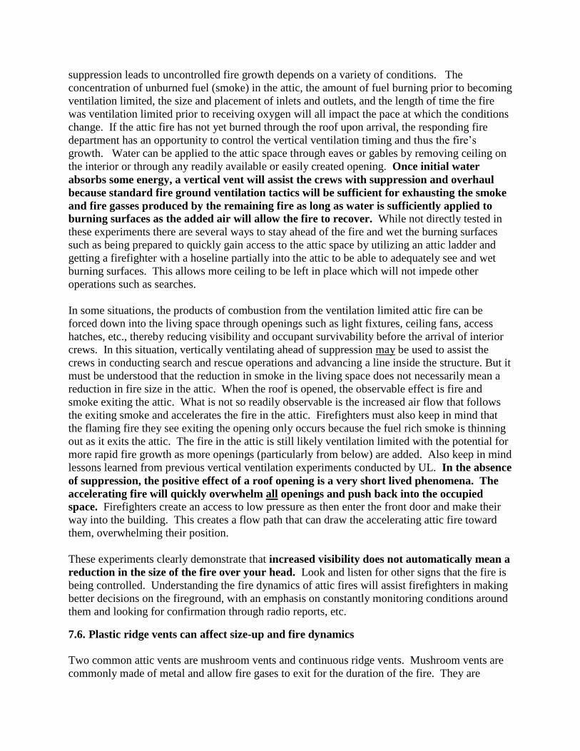
7.6. Plastic ridge vents can affect size-up and fire dynamics
Two common attic vents are mushroom vents and continuous ridge vents. Mushroom vents are
commonly made of metal and allow fire gases to exit for the duration of the fire. They are
installed on the slope of a peaked roof and the material, whether metal or plastic, flows away
from the opening if the mushroom cap melts. Continuous ridge vents are nearly always made of
plastic and allow fire gases to vent until they heat up. As the vents heat, the extruded plastic
melts and collapses on the opening at the peak, creating a very effective seal. The sealed
opening (the equivalent of 10 ft2 in these experiments) restricts air flow out of the attic, leading
to a ventilation limited fire. Thus, the true nature of the fire may be hidden during your size up.
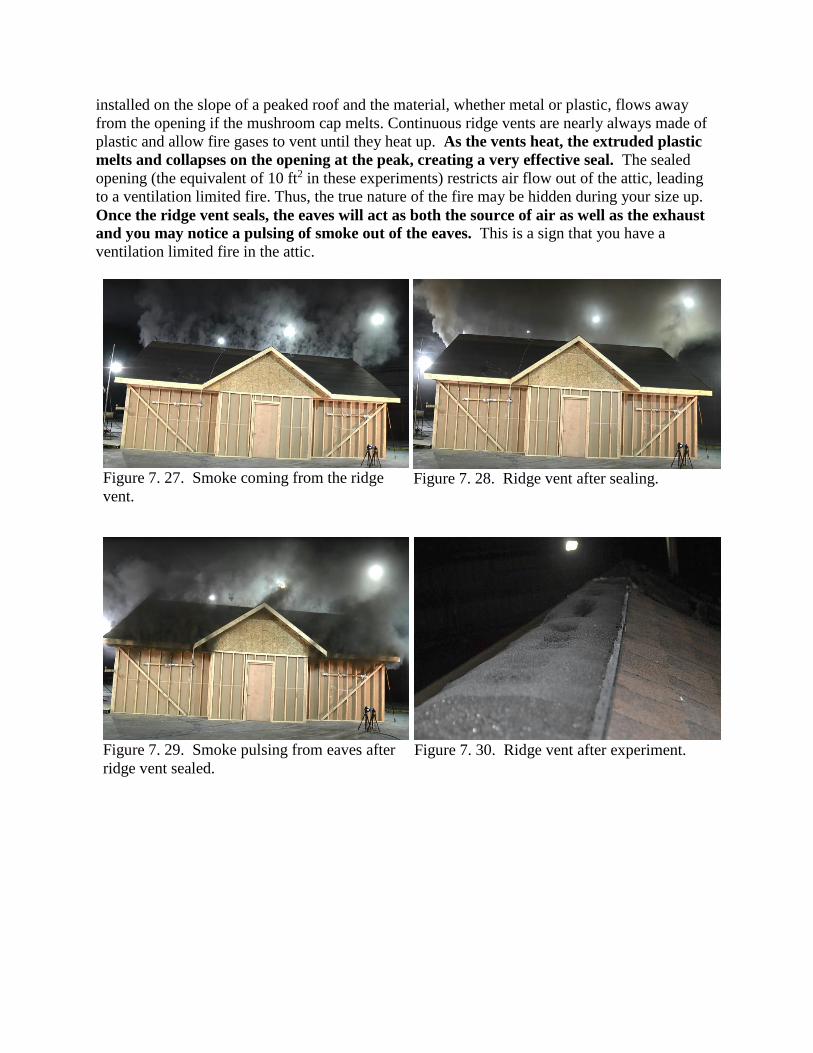
Once the ridge vent seals, the eaves will act as both the source of air as well as the exhaust
and you may notice a pulsing of smoke out of the eaves. This is a sign that you have a
ventilation limited fire in the attic.
Figure 7. 27. Smoke coming from the ridge
vent.
Figure 7. 28. Ridge vent after sealing.
Figure 7. 29. Smoke pulsing from eaves after
ridge vent sealed.
Figure 7. 30. Ridge vent after experiment.

Figure 7. 31. Section cut away after
experiment to see ridge vent seal.
7.7. Wetting Sheathing with an Eave Attack Slows Attic Fire Growth
The sheathing accounts for over 50% of the exposed surface area of the construction material
fuel in a typical attic. The sheathing is also in the best location to burn. Air enters at the eave
line, runs along the underside of the sheathing and exits through the peak, making this an optimal
place for burning. If crews wet the sheathing, either as part of an offensive fire attack or
defensively to slow fire spread to uninvolved sections of the structure, the major flame
spread mechanism in the attic is eliminated until the moisture evaporates. The other
construction material fuel in the attic is the trusses. The typical truss spacing of 24 inches
assisted in limiting fire spread from truss to truss. Wetting the sheathing further reduced truss to
truss fire transmission. Whether or not it is already involved in fire, wetting the sheathing allows
crews to ventilate or access the attic with a greatly reduced potential for rapid fire growth.
Figure 7. 36: Cut away showing water flow during eave attack.

Removing the soffit and flowing water along the eave line of these structures was the most
effective way to gain the upper hand on a fire that was venting through the roof. After the
fire ventilates through the roof, increased air is entrained through the eaves and burning is
increased. An eave attack puts water on these burning surfaces by flowing it up one side of the
attic to the peak, and then running down the other side. As water wets the sheathing, it also rains
down on the burning gases and other burning contents in the attic, extinguishing even more fire.
In these experiments, a 1 ¾ in. handline flowing approximately 150 gpm easily had enough
penetration to wet a 30 ft. by 36 ft. attic space under a 6/12 pitch roof system. Larger attics may
require larger flows with more penetrating ability. Additionally, if bird blocking or other
obstructions such as solid wood eaves are in place, they may need to be removed for this tactic to
be effective. Careful preplanning, site visits and the ability to profile buildings in your response
area will assist in the decision to make use of this tactic on the fire ground.
Figure 7. 32. Conditions at the start of eave
attack during Attic Experiment 4
Figure 7. 33. Conditions at the end of eave
attack during Attic Experiment 4
Figure 7. 34. Helmet cam view of water flow
into eaves.
Figure 7. 350. View into the eaves after Attic
Fire Experiment 4
7.8. Attic construction affects hose stream penetration.
The trajectory of the hose stream directed into an attic space is affected by the materials and
construction practices used to build attics. In legacy construction, wood rafters were used to
support the roof structure. Now, in modern construction, engineered trusses using less material
support the roof structure. Both of these construction methods were found to limit the
effectiveness of streams when traditional water application methods were used. Firefighters

attack room and contents fires by bouncing the stream off the ceiling and raining water down on
the fire. The geometry of the rafters, and especially the trusses, broke up the stream whether
applied from the occupied space below or from a gable vent, severely restricting the penetration
needed for this tactic to be effective in attic fires.
During the tests, only 1/3 of the attic was affected when water was applied through the gable
vent, regardless of the angle of attack. When attempted from the interior, a large amount of
ceiling needed to be removed in order to effectively wet all the surfaces in the attic.
The most effective water application takes into consideration the construction of the attic,
using the natural channels created by the rafters or trusses to direct the water onto the vast
majority of the surfaces. Application of water through open eaves along the entire eave line
allows water to impact over 2/3 of the attic space. When solid eaves are encountered or an
interior stream placement is chosen, the same tactical concept can be employed. The crew enters
the structure and makes its way to an exterior wall that is parallel to the line of the eaves.
Opening up a trough along this wall exposes the roof deck in much the same way as opening up
the eaves. Alternatively, when the building layout makes the peak more readily accessible, (for
instance, a building with a center hallway) a trough can be opened along the centerline of the
structure immediately below the line of the peak (Figure 7. 36). Water is then directed toward
the peak at as severe an angle as possible, alternately flowing water down both sides from the
peak to the eaves, wetting the sheathing and raining down on the other combustible contents in
the attic.

Figure 7. 36: Floor plan of a 2-story house showing where to open drywall on a center hallway
layout to effectively apply water to the sheathing by flowing down each rafter bay toward the
front and rear of house.
7.9. Consider flowing up instead of down with a master stream
When a fire grows in the attic space and burns through the sheathing or out of the gable ends,
crews may be called out and transitioned to a defensive operation. This has commonly included
putting up an aerial device and flowing water into the holes in the roof or gable ends with fire
coming out of them. This tactic typically fails to put much water on the underside of the roof
deck or onto any burning material or contents that are not directly beneath or in the immediate
vicinity of the hole. Large portions of the roof must burn away before angles of attack are
created that allow water to reach the burning materials. As an alternative, consider using an
aerial device or portable ladders and hand lines to open up the eaves and flow water into
the attic as was described in earlier tactical considerations. This approach could result in
controlling the fire enough to permit firefighting crews to transition back inside the
structure to complete searches, suppression, and overhaul.
If collapse is a concern, firefighters should not be placed in the collapse zone to accomplish this
tactic. A consideration when transitioning to the interior, when large amounts of water were
flowed into the attic the insulation will hold water and allow the ceiling to sag and collapse in
sections. In these experiments there was fiberglass batt insulation that protected the bottom
chord of the truss so collapse of the roof system did not occur but sections of gypsum board and

wetted insulation did fall into the interior where crews could be operating. Not all roof systems
are insulted in this manner so other roof collapse hazards could exist.
Figure 7. 372. Master stream flowing down
into attic fire and not into eaves.
Figure 7. 383. Potential to flow water where
fire is coming from instead of where fire is.
7.10. Knee Wall Fire Dynamics
Utilizing the upper ½ story of a structure for living space creates unique compartmentation not
found on lower levels of the building (Figure 7. 39 through Figure 10. 42). The interior living
space is surrounded on three sides by void spaces separated only by drywall and possibly
insulation (Figure 10. 43). During a structure fire, it is possible for fire to enter void spaces
and surround crews conducting interior operations before they notice a rise in temperatures
or see any signs of fire. Any penetration into the void space from the interior creates a flow path,
allowing fire to spread into the interior and exposing the crews. This fire spread may not occur
immediately following the opening of the wall or ceiling, as the void space fire is likely
ventilation limited. Thus, firefighters may breach a separation and then continue further into the
structure. Even though there is a delay between making the breach and the change in
conditions, once initiated, the transition to untenable conditions in the area of operation
occurs in seconds. In Figure 7. 44 the temperatures at 3 feet in the attic increased 300 degrees in
5 seconds. When things go bad, they go bad fast.

Figure 7. 39: North 9th St attic prior to
finishing
Figure 7. 40: North 9th St attic after finishing
Figure 7. 41: North 9th St from outside

Figure 10. 42. Knee wall construction details with drywall removed.
Figure 10. 43. Potential ventilation scenarios for 1/2 story structures.
Collar Beam
Roof Rafters
Knee Wall Framing
Knee Wall

Figure 7. 44. Temperature in living space during Knee wall field experiment shows fast
temperature change at 3 ft. crawling height of firefighter.
Knee wall construction often provides the potential for ideal fire growth, with air entering
low at the eave line and combustion gases exiting the peak through mushroom vents, ridge
vents or gable vents. The limited natural ventilation keeps the fire small and it normally
becomes ventilation limited. At the same time, the relatively large open space behind the knee
wall allows for the heating of large amounts of fuel to near its ignition point. Subsequent
ventilation, either by breaching the interior barrier or by venting at the roof, provides the
necessary flow path to rapidly grow the fire to flashover. When the barrier between the void
spaces and the occupied space fails or is breached, crews operating on the interior may find
themselves trapped between the new flow path and their means of egress. Conditions will
change even more rapidly if windows in the attic were opened or taken out, a common tactic
employed to improve visibility and assist the crews in locating the fire and/or victims. Open
windows provide even more air to mix with and ignite the rich fuel coming out of the knee walls.
In these experiments, UL replicated a scenario that has played out on many fire grounds (Figure
7. 45). The attack crew enters the attic space at the rear of the structure, chocking the doors open
as they enter the attic. Then they ventilate the window at the top of the stairs in an effort to
improve visibility and reduce heat in the occupied space. As smoke lifts, they work toward the
front of the structure looking for victims and the source of the fire. At the front, they ventilate
the front window to establish horizontal ventilation. With the hose line at the front of the attic, a
firefighter in the rear of the attic near the stairs opens the knee wall to look for the fire. When
this knee wall is opened, 3 flow paths are created. The previously hidden fire is connected to
openings at the entrance door, the rear window, and the front window. Air from the attic enters
the knee wall and mixes with the ventilation limited fire. When the mixture is right, there will be
1 ft.
3 ft.
5 ft.
7 ft.

a rapid increase in the energy produced and fire will travel along all the available flow paths
endangering and possibly trapping firefighters in the attic.
Figure 7. 45. Diagram with details about crew movement and ventilation locations
7.11. Apply water on a knee wall fire at the source and toward the direction of spread
before committing to the attic.
Applying water utilizing the same path the fire took to enter the void space may be the
most effective method at slowing fire growth. If the fire starts on the outside of the structure or
enters the knee wall due to auto exposure through an exterior window, controlling the source is
imperative to a successful fire attack. Water application to the knee wall will not be effective
until the source below it is controlled with direct water application. Once the source fire is
controlled, crews can more readily and safely gain access to the void spaces, extinguishing any
active fire in the void and wetting all exposed surfaces. This will prevent regrowth of the fire.
Attempting to initiate fire control only through a breach into the knee wall, or before the source
fire is effectively controlled, can place the attack crew in the flow path of a fire. If they cannot
effectively reach the source from their position, they will be pinned down as the fire continues to
spread and grow in the interconnected voids, eventually breaking out around or even behind
them.

Figure 7. 46. Fire on second floor with
extension into the knee wall. Water should be
flowed to extinguish the room (from inside or
outside) and then flow into the eaves (from
inside or outside) before accessing the attic.
Figure 7. 47. Fire on outside with extension
into the attic. Water should be flowed to
extinguish the exterior fire and then flow into
the eaves before accessing the attic.
7.12. Interior operations on knee wall fires
Knee wall construction creates interconnected void spaces where the wooden structural members
provide a relatively large surface area of exposed fuel along with air flow conducive to spreading
fire (Figure 7. 48). The experiments demonstrated that getting effective stream reach and
penetration inside a knee wall and other attic voids is hindered in much the same way as are
streams applied into open attics through gable ends or from the floor below (Figure 7. 49). In
both cases, structural members effectively broke up the stream before it could successfully
penetrate the fire area. The experiments also demonstrated that water should initially be applied
into the knee walls at multiple locations through small holes, in order to suppress the burning
gases, before large sections of the knee wall are opened for complete extinguishment. This tactic
will maximize the benefit of energy absorption through steam conversion while minimizing the
spread of fire along the flow path created by the openings made for the nozzle. Once the gases
are suppressed or cooled, focus on getting water into the rafter bays where air moving from the
eave line to the peak will sustain and accelerate the remaining fire. This is similar to the concept
that makes the eave attack successful; the sheathing is where the air and fuel come together most
effectively, so this is where suppression efforts should be focused. Don’t wait to see fire in a
knee wall before you apply water to the void space or the surfaces. Tests have demonstrated
that the most effective way to get a handle on knee wall fires is to control the source fire,
cool the gasses prior to making large breaches in the barrier, and then aggressively open
the knee walls to complete extinguishment, focusing on wetting the underside of the roof
decking.

Figure 7. 48. Knee wall access showing difficulty of flowing water past the rafters.
Figure 7. 49. Diagram showing deflection of water flow and inability to penetrate full length of
the knee wall.

8. Acknowledgements:
The authors would like to acknowledge the financial support of the Department of Homeland
Security’s Assistance to Firefighters Grant Program’s Fire Prevention and Safety Grants, in
particular the staff members Dave Evans, Ellen Sogolow, Lillian Ricardo and Maggie Wilson for
their guidance and expertise.
In addition we would like to acknowledge the Milwaukee Fire Department. The acquired
structures utilized in the field experiments along with the manpower and support provided were
vital. Without their tireless efforts the work on knee wall fires would not have been possible.
The authors would also like to acknowledge Nicholas Traina, a graduate student at the
University of Illinois, for his assistance with the project.
DISCLAIMER In no event shall UL be responsible to anyone for whatever use or nonuse is made of the information contained in this Report and in no event
shall UL, its employees, or its agents incur any obligation or liability for damages including, but not limited to, consequential damage arising
out of or in connection with the use or inability to use the information contained in this Report. Information conveyed by this Report applies
only to the specimens actually involved in these tests. UL has not established a factory Follow-Up Service Program to determine the
conformance of subsequently produced material, nor has any provision been made to apply any registered mark of UL to such material. The
issuance of this Report in no way implies Listing, Classification or Recognition by UL and does not authorize the use of UL Listing,
Classification or Recognition Marks or other reference to UL on or in connection with the product or system.

UL FIREFIGHTER SAFETY RESEARCH INSTITUTE
UL’s Firefighter Safety Research Institute is dedicated to increasing firefighter knowledge to reduce injuries and deaths in the fire
service and in the communities they serve.
Working in partnership with the fire service, research departments and agencies, FSRI executes cutting-edge firefighter research and makes the results widely available to the global fire community. With a team of pioneering experts and access to UL’s leading infrastructure,
equipment and vast knowledge and insights, FSRI conducts and disseminates cutting-edge research and training programs that focus on the changing dynamics of residential, commercial
and industrial fires, and the impact they have on the fire service tactics and strategies
Visit Us: ULfirefightersafety.com Like Us: facebook.com/ULfirefightersafety
Follow Us: twitter.com/UL_FSRI Email: [email protected]


