NO. REV. NO. : . . First Crew Engineering Evaluation of ATM-959 ' the Array E - LSPE Geophone Cable Reel PAGE 1 OF 9 Aerospace Systems Division DATE 1/29/71 A. INTRODUCTION On January 22, Crew Engineering performed a lG, space-suited performance test with an Engineering Model of the LSPE Geophone Cable Reel. This test was a continuation of a Crew Engineering evaluation started on January 18 with a "shirt sleeve" test. The purpose of these tests was to determine if the chosen geophone cable reel configuration would pre sent any basic handling and deployment problems to the crew. Prepared by: R. Deppe Crew Engineering
Transcript
NO. REV. NO.
: . . First Crew Engineering Evaluation of ATM-959
' the Array E - LSPE Geophone Cable Reel
PAGE 1 OF 9 Aerospace Systems Division
DATE 1/29/71
A. INTRODUCTION
On January 22, Crew Engineering performed a lG, space-suited performance test with an Engineering Model of the LSPE Geophone Cable Reel.
This test was a continuation of a Crew Engineering evaluation started on January 18 with a "shirt sleeve" test.
The purpose of these tests was to determine if the chosen geophone cable reel configuration would pre sent any basic handling and deployment problems to the crew.
Prepared by: ~ .9~ R. Deppe
Crew Engineering
NO. REV. NO • . • : I
First Crew Engineering Evaluation of ATM-959
the Array E - LSPE Geophone Cable Reel
PAGE 2 OF 9 Aerospace Systems Division DATE 1/29/71
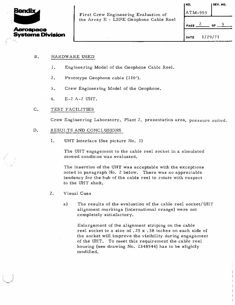
The UHT engagement to the cable reel socket in a simulated stowed condition was evaluated.
The insertion of the UHT was acceptable with the exceptions noted in paragraph No. 2 below. There was no appreciable tendency for the hub of the cable reel to rotate with respect to the UHT shaft.
2. Visual Cues
a) The results of the evaluation of the cable reel socket/ UHT alignment markings (international orange) were not completely satisfactory.
Enlargement of the alignment striping on the cable reel socket to a size of • 25 x . 38 inches on each side of the socket will improve the visibility during engagement of the UHT. To meet this requirement the cable reel housing (see drawing No. 2348544) has to be slightly modified.
NO. REV. NO.
: . . First Crew Engineering Evaluation of ATM-959
the Array E - LSPE Geophone Cable Reel
PAGE 3 OF 9
Aerospace Systems Division
DATE 1/29/71
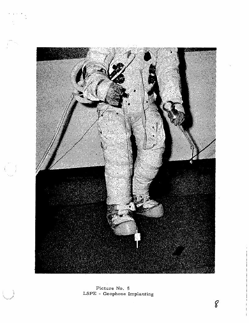
b) Increasing the length of the UHT alignment striping from the present 1. 00 inch to 2. 50 inches (See Fig. 1, Page 9), will improve visibility since the UHT ingresses further into the geophone cable reel socket than in any previous ALSEP design.
Additional Crew Engineering tests will be performed after integration of the geophone module which is in fabrication at this time.
3. Geophone cable deployment (See picture No. 2) approx. 110 ft. of prototype cable has been deployed with satisfactory results.
The proposed flag on the cable signalling the end of the cable deployment procedure, as well as the tactile feedback provided by the tape on the cable, are important assets.
4. Geophone removal & deployment (See pictures No. 3 and No. 4).
The removal of the geophone from the reel housing has been found acceptable.
This test should be repeated with a completed engineering model because the clip (See Drawing No. 234854 7, part 5)
did not have the final prototype dimensions.
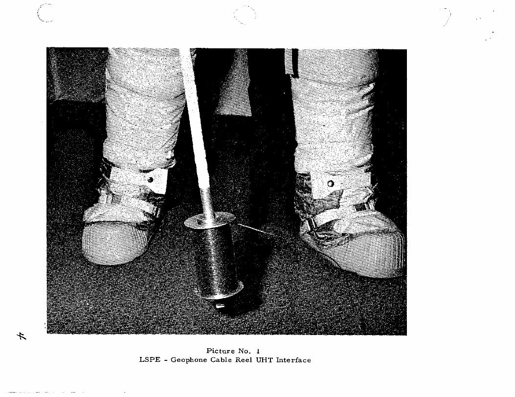
Picture No. 5 depicts the test subject pedally implanting the geophone. An alternate approach would be to use the base of the cable reel/UHT to emplant the geophone.


![[Array, Array, Array, Array, Array, Array, Array, Array, Array, Array, Array, Array]](https://static.documents.pub/doc/80x56/56816460550346895dd63b8b/array-array-array-array-array-array-array-array-array-array-array.jpg)


