26
By T SHYAMKUMAR 14TH14F
| Date post: | 13-Jul-2015 |
| Category: |
Engineering |
| Upload: | shyam-kumar |
| View: | 216 times |
| Download: | 2 times |

By
T SHYAMKUMAR
14TH14F

Why micro combustion ? Batteries have low specific energy
Liquid hydrocarbon fuels have a very high specific energy
To reduce system weight
To increase operational lifetimes
To reduce unit cost
Easily rechargeable
APPLICATIONS
Micro-satellite thrusters for station keeping require a small thrust and a high specific impulse for an operation period of years. An efficient micro-thrusterrequires propellants with a large energy density
Micro-air vehicles for reconnaissance and surveillance in urban and battle field.
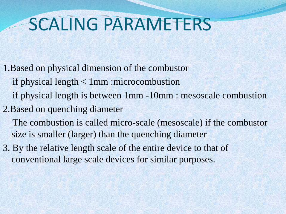
SCALING PARAMETERS
1.Based on physical dimension of the combustor
if physical length < 1mm :microcombustion
if physical length is between 1mm -10mm : mesoscale combustion
2.Based on quenching diameter
The combustion is called micro-scale (mesoscale) if the combustor
size is smaller (larger) than the quenching diameter
3. By the relative length scale of the entire device to that of
conventional large scale devices for similar purposes.

Thermo physical Issues As the characteristic length of the device is reduced, the
Reynolds and Peclet numbers decrease and fluid flow tends to be less turbulent, so the viscous effects and the diffusive transport of mass and heat become increasingly important.
From the point of view of combustion, an important issue is the magnitude of the residence time, because it decreases as the length of the combustor decreases, and it has to be larger than the chemical time, for complete combustion to occur.
At the length scales of microcombustion devices, heat
transfer by natural convection becomes small because the induced buoyant flow is small
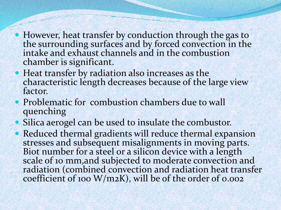
However, heat transfer by conduction through the gas to the surrounding surfaces and by forced convection in the intake and exhaust channels and in the combustion chamber is significant.
Heat transfer by radiation also increases as the characteristic length decreases because of the large view factor.
Problematic for combustion chambers due to wall quenching
Silica aerogel can be used to insulate the combustor. Reduced thermal gradients will reduce thermal expansion
stresses and subsequent misalignments in moving parts. Biot number for a steel or a silicon device with a length scale of 10 mm,and subjected to moderate convection and radiation (combined convection and radiation heat transfer coefficient of 100 W/m2K), will be of the order of 0.002

Combustion Physical time available for combustion (residence time) must be larger
than the time required for the chemical reaction to occur (combustion time).
Since in general the residence time will be small in micro combustors, it is important to have small chemical times to ensure completion of the combustion process within the combustor .
As engine size or combustion volume decreases, the surface-to-volume ratio increases, resulting in increased combustor surface heat losses and increased potential destruction of radical species at the wall.
Ceramic materials, such as SiO2, SiC, and Si3N4, can withstand temperatures of around 1700 K, which are high enough to ensure short chemical times
Although the increase of the surface-to-volume ratio of the combustor presents a problem for gas-phase combustion, it favors catalytic combustion

Flame propagation and stabilization When flames (e.g., a torch) are put in narrow
channels, they do not propagate through, when the gap size is below what is known as the quenching distance
Quenching distance is in the range of ~2.5 mm for cold walls (500 K)
Burner insulation and thermal management are important in minimizing heat loss and mitigating thermal quenching
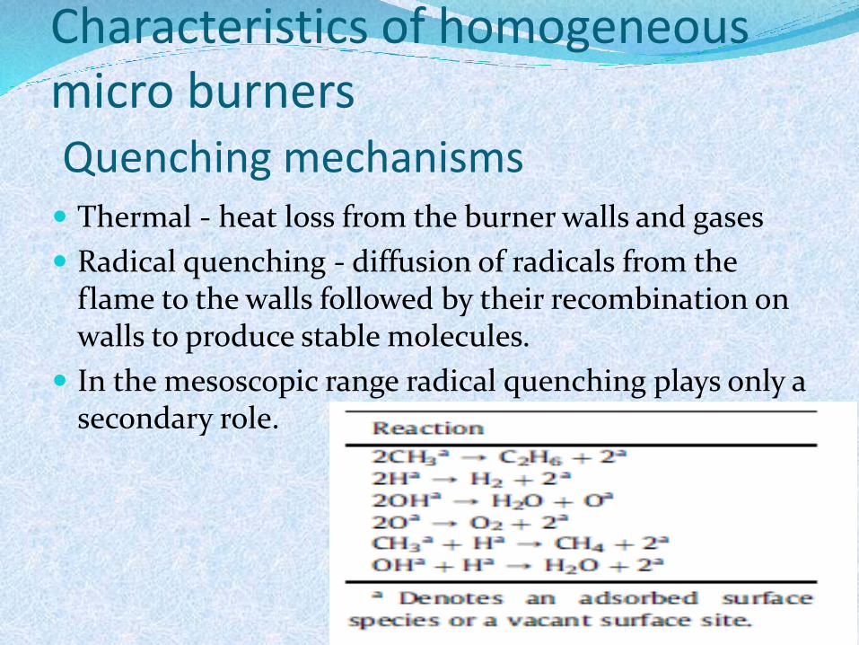
Characteristics of homogeneous micro burnersQuenching mechanisms Thermal - heat loss from the burner walls and gases
Radical quenching - diffusion of radicals from the flame to the walls followed by their recombination on walls to produce stable molecules.
In the mesoscopic range radical quenching plays only a secondary role.
The excess enthalpy principle
Qin - enthalpy of the inlet stream .
Qc - heat generated on combustion.
Qin + Qc - outlet enthalpy in an adiabatic system.
Sufficient pre-heating of the incoming gases is required to stabilize combustion in microburners.
Qr is recirculted to cold inlet stream.
Maximum temperature is greater than the adiabatic temperature rise .

The role of burner walls Wall conductivity and the wall thickness are key
parameters for flame stability.
Direction of transverse heat transfer downstream of the flame is from hot gases to the wall and upstream of the flame is from the wall to the cold inlet gases
Micro burner can be split into three distinct zones: the pre-heating, the combustion and the post-combustion zones.

Micro burner stability1 The dual role of walls in heat exchange
As the wall conductivity decreases, the flame temperatures become higher and the flame remains localized but drifts downstream due to insufficient pre-heating.
Highly conductive walls, on the other hand, dissipate heat to the environment and also longitudinally, causing the entire burner surfaces to be hot
Two modes of flame quenching occur: a spatially ‘distributed’ type for high wall thermal conductivities, thick walls, and/or low flow velocities and blowout at high velocities, low wall conductivity, or thin walls.

2 Effect of flow velocity
The inlet velocity is easily varied experimentally and controls the power input to a burner
At low flow velocities, the power input is low, the burner temperatures are low and extinction is the dominant quenching mechanism.
At high flow velocities the power input is high but the residence time is low, and as a result blowout is the dominant quenching mechanism.
For fast flows, higher wall conductivity facilitates heat transfer upstream resulting in more stable flames

Excess enthalpy burners(heat recirculation) Thermal enthalpy of the
incoming reactants is increased via preheating without diminishing the chemical enthalpy via chemical reaction.
A PC with LabViewsoftware is used to control mass flow controllers for fuel and air and to record data from thermocouples for temperature measurement. The exhaust gas composition was analyzed with a gas chromatograph. Electrically heated Kantalwire is used for ignition

Heat recuperation in reverse-flow micro burners
Temporal thermal coupling between the hot product and the cold reactant streams, achieved through periodic flow reversal in reverse-flow (RF) reactors.
Requirements - high gas-solid heat transfer rates and reasonably high heat capacity of the burner solid structure. Porous beds are required to increase the gas-solid heat transfer rates
The RF operation improves the microburner stability at the blowout limit, but does not affect the stability at extinction.Micro burner stability increases as the wall thermal conductivity is reduced.
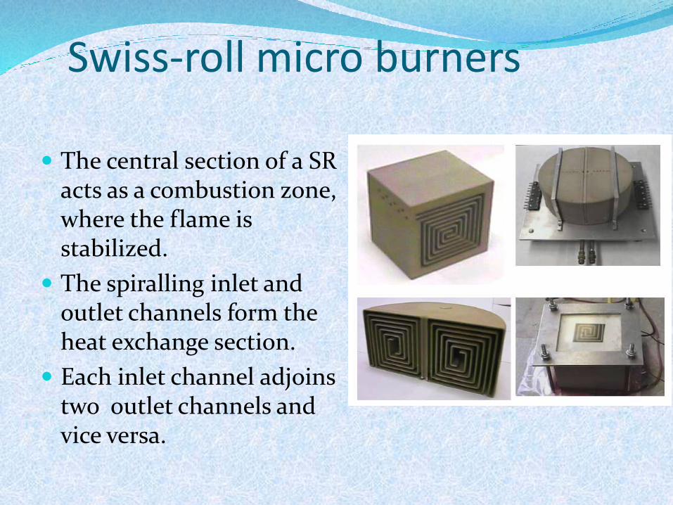
Swiss-roll micro burners
The central section of a SR acts as a combustion zone, where the flame is stabilized.
The spiralling inlet and outlet channels form the heat exchange section.
Each inlet channel adjoins two outlet channels and vice versa.
Continued.. A catalyst may also be included in the combustion zone to
improve burner stability and to reduce the ignition temperature
At low inlet velocities, close to or lower than the laminar flame speed, the flames are located upstream of the combustion zone.
The SR heat exchanger then acts as a net heat sink.
When the velocity is increased, the flame gets anchored in the central combustion zone. Further increase in the velocity pushes the flame downstream and into the recirculating section. Blowout is reached soon thereafter

Micro burner geometry
The wall thickness, gap width, and reactor length are the three parameters that can be varied
Increasing the gap width decreases the net transverse heat transfer;higher gap sizes are preferable at the extinction limits, where heat loss from the flame results in thermal quenching.
Narrower gap sizes improve the heat transfer that can stabilize the blowout limit.
Increasing the reactor length shrinks the region of self-sustained combustion, due to increased heat losses through the reactor solid structure.
Catalytic micro combustion In contrast to gas phase combustion, catalytic combustion
occurs at a surface reaction without a flame.
Surface reactions are not very sensitive to the reduced size of micro-combustors, which implies the possibility of further shrinking of micro-combustors.
Lower temperature of catalytic combustion makes thermal stresses, materials limitations and heat losses less problematic.
Self-starting fuels and catalysts are highly desirable because it would eliminate the need for glow plugs, supplemental battery, electronics, etc
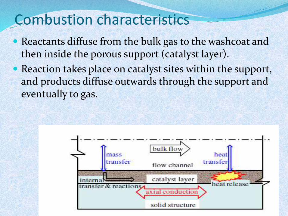
Combustion characteristics
Reactants diffuse from the bulk gas to the washcoat and then inside the porous support (catalyst layer).
Reaction takes place on catalyst sites within the support, and products diffuse outwards through the support and eventually to gas.

Stability of catalytic micro burners
Catalytic micro burners have superior stability than homogeneous ones.
Blowout stability limit is much higher in catalytic
combustion than in homogeneous combustion.
catalytic burner stability is affected from the fuel choice.
Catalytic combustion of methane is difficult to sustain whereas combustion of propane, hydrogen, and methanol on Pt can be sustained .

.
Hydrogen dissociation is a non-activated reaction
Hydrogen self-ignites on Pt at room temperature (i.e., it does not require external heating).
Methane adsorption on noble metals is activated (an activation energy of~11 kcal/mol on Pt) rendering its combustion slow. As a result, heat is not generated fast enough to compensate for heat losses

Where is catalyst placed?
For a microburner length is 2 cm only 1cm is catalytic.
The catalyst is placed in the front, middle, or rear part of the burner.
Catalyst placement is more important for low conductivity walls where axial heat transfer is slow. At high conductivities, catalyst placement is of secondary importance.
Porous media micro-combustion
In conventional combustion, the combustion process occurs in a mostly gaseous environment, convection is the main mode of pre-heating.
Whereas in porous media, the combustion takes place in a three dimensional solid porous matrix having interconnected pores. Apart from convection, the conduction and radiation modes of heat transfer are also activated. This enhances the heat transfer (pre-heating) from the burned hot gases to unburned mixture.
These characteristics seem favorable to micro-combustion because the pre-heating is useful in increasing the flame temperature, and therefore sustaining flames in a smaller space.
A higher and more uniform temperature distribution can be achieved along the wall of the microcombustor.

Conclusions
Given the nearly hundredfold mass-based greater energy density of fuels, an improvement over batteries could be achieved if greater than 1% of the energy stored in chemical bonds could be converted to electricity
Catalytic combustion is superior at these scales over its homogeneous counterpart and can be sustained for fairly large heat losses, much lower wall conductivity materials, and much higher inlet velocities but not necessarily with complete fuel conversion.
References[1].S.K. Chou, W.M. Yang, K.J. Chua , J. Li K.L. Zhang,” Development of micro
power generators – A review”, Applied Energy 88 (2011) 1–16
[2]. A.Carlos Fernandez-Pello, “micropowergeneration using combustion:Issuesand Approaches”, Proceedings of the Combustion Institute, Volume 29, 2002,pp. 883–899
[3]. Uttam Rana, Suman Chakraborty, S.K. Som,” Thermodynamics of premixed combustion in a heat recirculating micro combustor”, Energy 68 (2014) 510-518
[4].Niket S. Kaisare a, Dionisios G. Vlachos,” A review on microcombustion: Fundamentals, devices and applications”, Progress in Energy and Combustion Science 38 (2012) 321-359
[5]. Nam Kim , Souichiro Kato , Takuya Kataoka , Takeshi Yokomori ,Shigenao Maruyama, Toshiro Fujimori , Kaoru Maruta ,” Flame stabilization and
emission of small Swiss-roll combustors as heaters”, Combustion and Flame 141 (2005) 229–240..


