Flames of Fuel Jets 30 DIFFUSION IN LAMINAR FLAME JETS l By H. C. HOTTEL2 AND W. R. HAWTHORNE3 SUMMARY The lengths and concentration patterns of flames from circular nozzles burning in free air have been determined over a wide range of veloci- ties with several nozzle diameters and for various gases and primary air-gas ratios. As the nozzle velocity is increased from zero the flame, burning under conditions of diffusional mixing with air, increases in length until a transition occurs to turbulent combustion with a consequent change in flame length to a value which is substantially independent of further increase in velocity.' The present paper covers that portion of the data related to laminar jets and to transition phe- nomena. The progress of combustion is treated analytically, assuming that molecular diffusion is controlling and that the concentration of oxygen and fuel are zero at the flame interface. A relation is obtained between the time of flow of fuel gas to the flame tip and the proportion of nozzle fluid and air required for complete combustion as follows: 1/0: = 4log,(1 + a,) \at -- a0/ where o: = 4D,Q/D2 Dr = molecular diffusivity t: = time of flow from nozzle to flame tip D = nozzle diameter a, = tools air/tool fuel gas for complete combustion a0 = mols air/mol fuel gas in nozzle fluid This paper is part of a thesis by W. R. Hawthorne submitted in 1939 to the Massachusetts Institute of Technology in partial fulfillment of the requirement for the ScD. 2Professor of Fuel Engineering, Massachusetts In- stitute of Technology. aWestinghouse Professor of Mechanical Engineer- ing, Massachusetts Institute of Technology. 254 When the flame is short the time of flow is propor- tional to flame length, L; for longer flames, the generalized flow-time for a given nozzle fluid, Of, should be a function of L/D, volumetric flowrate, Q, diffusivity, D~, and the Grashof group which enters wherever the major force overcoming vis- cous drag is one of buoyancy. The actual rela- tionship is established empirically from data on flames of carbon monoxide and of city gas. For flames longer than 6 inches, issuing from nozzles of diameters 0.125 to 0.82 inches, the following relation is suggested: L -- AlogQ0: +B, where A and B are constants depending only on the fuel gas and the primary air-fuel ratio. Data on phenomena of transition from laminar to turbulent flow in the flame jet are also pre- sented. INTRODUCTION Industrial gas-fired furnaces are characterized in a large number of cases by the mixing of the fuel gas and air streams in the combustion cham- ber of the furnace, so that the propagation of combustion is dependent on the rate of mixing of gas and air. A basic understandingof problems in combustion chamber and burner design, flame placement, and flame impingement thus requires the application of the concepts of mass transfer to the mixing process in flames. This mixing may occur in two ways: (1) Molecular diffusion. The mixing of two streams by molecular diffusion is relatively slow, and diffusion flames are used when a long, slow flame is desirable for the dis- tribution of heat over large areas in the furnace. Such flames are used, for example, in rotarykilns.
Transcript
Flames of Fuel Jets
3 0
D I F F U S I O N IN LAMINAR F L A M E JETS l
By H. C. HOTTEL2 AND W . R. HAWTHORNE 3
SUMMARY
The lengths a n d concentration patterns offlames from circular nozzles b u r n i n g in free airhave been determined over a wide r a n g e of veloci-ties with several nozzle diameters a n d for variousg a s e s a n d primary a i r - g a s ratios. As the nozzlevelocity is increased from zero the flame, b u r n i n gu n d e r conditions of diffusional mixing with air,increases in l e n g t h u n t i l a transition occurs tot u r b u l e n t combustion w i t h a consequent changein flame length to a v a l u e w h i c h i s substantiallyindependent of further increase in velocity.'
The present p a p e r covers that portion of thed a t a related to l a m i n a r jets a n d to transition phe-nomena. The progress of combustion is treatedanalytically, a s s u m i n g that molecular diffusion iscontrolling a n d that the concentration of oxygena n d fuel are zero a t the flame interface. A relationi s o b t a i n e d b e t w e e n the t ime of flow of fuel gasto the flame tip a n d the proportion of nozzle f lu ida n d air r e q u i r e d for complete combustion a sfollows:
1/0: = 4 l o g , ( 1 + a , )\ a t -- a 0 /
w h e r e o: = 4 D , Q / D2
Dr = molecular diffusivityt: = t i m e of flow from nozzle to flame tipD = nozzle diametera , = tools air/tool fuel gas for complete
combustiona0 = mols a i r / m o l fuel gas in nozzle f lu id
This paper is part of a thesis by W . R. Hawthornesubmitted in 1939 to the Massachusetts Institute ofTechnology in partial fulfillment of the requirementfor the ScD.
2 Professor of Fuel Engineering, Massachusetts In-stitute of Technology.
a Westinghouse Professor of Mechanical Engineer-ing, Massachusetts Institute of Technology.
254
When the flame is s h o r t the t ime of flow is propor-tional to flame length, L ; for longer flames, thegeneralized flow-time for a g i v e n nozzle fluid, Of,s h o u l d be a function of L/D, volumetric flow r a t e ,Q, diffusivity, D~, a n d the Grashof g r o u p w h i c henters wherever the m a j o r force overcoming vis-cous d r a g is one of buoyancy. The a c t u a l r e l a -tionship is established empirically from data onflames of c a r b o n monoxide a n d of city gas. F o rflames longer than 6 inches, i s s u i n g from nozzlesof diameters 0.125 to 0.82 inches, the followingrelation is suggested:
L -- A l o g Q 0 : + B ,
w h e r e A a n d B are constants depending only o nthe fuel gas a n d the primary air-fuel ratio.
D a t a on phenomena of transition from l a m i n a rto t u r b u l e n t flow in the flame jet are also pre-sented.
INTRODUCTION
I n d u s t r i a l gas-fired f u r n a c e s a r e characterizedin a l a rge n u m b e r of c a s e s by the mixing of thefuel gas a n d a i r s t r e a m s in the combustion cham-b e r of the furnace, so that the propagation ofcombustion is dependent on the rate of mixing ofgas a n d air. A b a s i c u n d e r s t a n d i n g of problemsin combustion c h a m b e r a n d b u r n e r design, flameplacement, a n d flame impingement thus requiresthe application of the concepts of m a s s transferto the mixing process in flames. This mixing m a yo c c u r in two w a y s :
(1) Molecular diffusion. The mixing of t w os t r e a m s by molecular diffusion is relativelys low, a n d diffusion flames are u s e d when along, slow flame is desirable for the dis-tribution of heat over l a rge a r e a s in thefurnace. S u c h flames are used , for example,in r o t a r y kilns.
FLAMES OF FUEL JETS 255
(2) Turbulent mass transfer or eddy dif fus ion.In th i s case mass transfer is much morerapid than for molecular di f fus ion, sincemixing occurs by the intermingl ing of micro-particles of f lu id . W h e r e high t h e r m a l ou t -put per uni t of f u r n a c e vo lume is required,as in p o w e r plant operat ion, i t is necessaryto produce a turbulent flame.
I n laminar flow, mix ing i s by molecular diffusionon ly , whereas in turbulent flow i t i s largely byeddy diffusion or convect ion, wi th the final h o m o -
poin t along the f lame w h e r e breakdown of laminarflow occurs and a turbulent j e t develops. Thedistance from the nozzle to the p o i n t w h e r e theturbulent b r u s h begins may be t e r m e d the b r e a k -poin t length . Character is t ic f lame length andbreakpoint length curves have been obtained forvarious nozzles and fuel gases; one such set ofcurves i s shown in figure 1. The appearance ofthe diffusion and turbulent flames is demonstratedby the sketches in figure 2 . As the nozzle veloci tyincreases from zero t h e r e is at f i rs t an almost pro-
2 4
20
" 16tu
v.
Z)
t ot o
8
I00 200 300
N O Z Z L E VELOCITY, FIT / SEC.
FIG. 1. Effect of nozzle velocity on f lame length of ci ty gas flames with no primary air; { inch diameter nozzle;from Gaunce (5).
geneity being attained by molecular diffusionbetween small -scale eddies .
The f lame from a circular nozzle provides as imp le i l lus t ra t ion of the difference between b u r n -ing and mixing in laminar and in turbulent flow.When fuel gas discharges at velocities below acritical value from the nozzle in to q u i e t a i r oflarge extent , the flow of. gas is laminar, and themixing of gas and a i r occurs by molecular diffusionin a th in f lame surface w h i c h i s fixed in space.As the nozzle veloci ty is increased the diffusionflames increase in length unt i l a critical veloci ty i sreached and the t ip of the f lame becomes u n s t e a d yand begins to flutter. With further increase inveloci ty th i s unsteadiness develops in to a noisyturbulent brush of f lame star t ing at a def in i te
~ ° ' ~ L % ~ ' " ~ I ; ~°" ~!' ; o % ~ t ~ &
--INCREASING NOZZLE VELOCITY - ' - ~ "
FIo. 2. Progressive change in f lame type with in-crease in nozzle velocity.
portional increase in f lame length , and at anyveloci ty in th i s region the' f l a m e is.sharp-edgedand constant in shape. When a sufficient ly high
256 T H I R D S Y M P O S I U M O N C O M B U S T I O N , F L A M E A N D E X P L O S I O N P H E N O M E N A
veloci ty is reached (fourth sketch) the t ip of thef lame changes in character, and a s l igh t b r u s hforms. With further increase in nozzle veloci tythe poin t at which the f lame " b r e a k s " movest o w a r d the nozzle, and the t ip of the f lame movest o w a r d a new height different from that of thelongest pure diffusion f lame (in the present exam-ple, shorter). At a nozzle veloci ty correspondingto the seventh sketch the break-point has ap-proached qu i t e c lose to the nozzle, and substan-t ia l ly the whole f lame has become turbulent .Fflr ther increase in veloci ty affects the total f lamelength and break-point very l i t t le , but f lame no i secontinues to increase and f lame luminos i ty con-tinues to decrease. The f lame final ly blows offthe port at a veloci ty of 50-1000 feet per second,depending on the gas , f lame p i lo t , and nozzle size.
A study of these flames was undertaken with theobject of applying the concepts of mass transferto mix ing in the flames. In th i s p a p e r only thework on diffusion flames and diffusion f lame break-down is discussed; two l a t e r papers cover the workon turbulent flames and the i r representation byl iqu id models .
DI:F~'USION F L A M E S
Measurements of the length of ci ty gas diffusionflames issu ing in to q u i e t a i r from a circular nozzlewere made by R e m b e r t (1). Cuthber tson (2)made similar measurements, but does not ident i fythe fuel gas he used.
The s h a p e and characteristics of diffusion flamesin which the veloci ty of the mixing streams wasextremely low were studied by B u r k e and Schu-mann (3). They gave a s impl i f ied mathematicalanalysis of the diffusion process which enabledf lame shapes to be determined theoret ical ly. The-oretical predict ions were in good agreement wi tht h e i r experimental resul ts .
E X P E R I M E N T A L APPARATUS
A circular b u r n e r nozzle to which were ledk n o w n quanti t ies of gas (and in some cases primaryair) was si tuated at the bot tom of a vertical cylin-drical furnace of relat ively large dimens ions ,figure 3 . A k n o w n quant i ty of secondary a i r wasintroduced at the bot tom of the furnace throughstraighteners and screens, so that a uniform, steadyand slow flow of a i r was provided for the combus-t ion and scavenging. T h r e e sizes of b u r n e r portwere used, ] inch, ~g inch, and ] inch inside d i a m -eter (f ig . 4). To minimize rotat ion and turbulencein the issu ing gas , straighteners and screens were
placed in the pipe before the gas stream was con-t r a c t e d down to one-ninth of i t s cross-sectionala r e a . The contraction was followed by a stra ightsect ion, s ix port diameters long , which was longenough to p r e v e n t the issu ing jet from wobbl ingand short enough to prevent excessive develop-ment of turbulent veloci ty components , or tocause a not iceable departure from uniform veloci tyover the cross sect ion of the stream.
The measurement of gas and primary a i r flowwas carried out by orifice meters wi th an accuracyof 1½ percent. Two scales placed on either sideof the f lame enabled the pos i t ion of a given poin tin the f lame relative to the b u r n e r port to bemeasured to wi th in ± 2 ram. In the region oft ransi t ion from laminar to turbulent jet the break-
poin t tended to be somewhat unstable, so that thereproducibi l i ty of the measurement was wi th in-+0.5 cm. in th i s region. Reproducibi l i ty wasconsiderably b e t t e r at higher veloci t ies , where thebreakpoint was more stable. The f lame lengthswere reproducible to wi th in ±0.5 cm. F l a m elength measurements were made with the f u r n a c etop removed. Gas sampl ing in the f lame wasdone with the furnace top in place as describedbelow.
To obtain samples of gas from the flames awater-cooled sampl ing tube was used, figure 5 .A th in brass wedge was arranged to, project down-w a r d s from a horizontal water-cooled t u b e . Sam-ples were withdrawn from the th in edge of the
:FLAMES OF :FUEL JETS 257
wedge through seven stainless s t e e l t u b e s , .e25 inchinside diameter, w h i c h were soldered to 1 incho.d. copper t u b i n g ins ide the water-cooled t u b e .The s e v e n sampling points were s i t u a t e d half aninch b e l o w the center of the water-cooled tube of
inch diameter; a n d t h e r e was no observable dis-t u r b a n c e to the gas flow up to the sampling point .
+1"v.r DIA. r ~ IF I T JET
in the s t u d y of t u r b u l e n t flames (to be d e s c r i b e din another paper).
9TFFUSm~¢ I'~OCESS IX T~E ~'LA~E
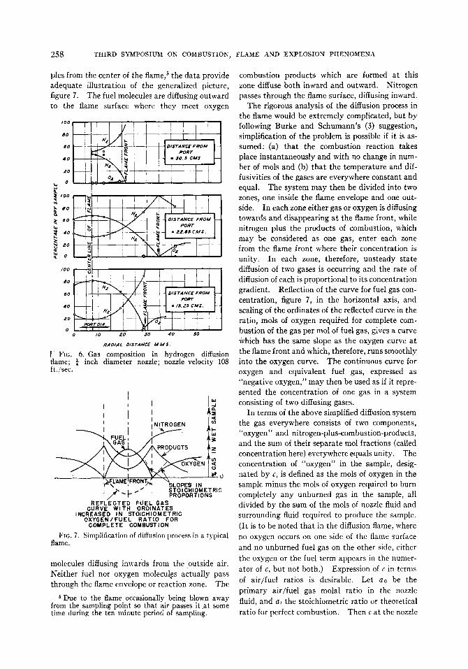
The process of diffusion occurring in a flame ofhydrogen leaving a port ¼ inch diameter a t avelocity of 108 ft./sec. 4 is illustrated in figure 6 ,
BUNDLE OF F 4 V~ ,@.
STRAIGHTENERS / BRASS I ,,
SCREEN ~ ~ I SCRd~N ~ ~ A .
I '/z" ~ [ 4 LENCTHS-~$~3; e'; ~°AND IZ" [ ~-Jl
4ALUMINUM F~OO ~OR ALI@NING , . le t
Z l / Z .~- I ~ , ~ " .
• , ~
$//; J E r
I~ xy~ u Z '~gl
or.--_ ~ ._ t
//8"ME TFIo. 4 . Details of rounded nozzles.
•s 1,l, ~ J/&"o~A. '//6" o.0. COPPER
TUBING 37~,D IA
, /-~ B R A S S ST#//=' -H ~-~}
DRILLED. 028•DIA.FITTED WITH $.S. NEEDLES
.015 *L O. pOg$"O. O., t/~."L ONG
• CALE I , , , I , , , I/ iNCH
Fro. 5 . Water-cooled sampling tube.
\\ 1 _ III I L
The samples were d rawn out simultaneously a n dstored in sample bottles to a w a i t analysis. Thet ime t a k e n to o b t a i n one b a t c h of seven s a m p l e swas approximately ten m i n u t e s ; a n d d u r i n g thist ime the gas a n d air flows were maintained s t e a d yu n d e r the action of pressure-regulating valves.This same apparatus was u s e d to a l i m i t e d extent
in w h i c h the analyses of s a m p l e s t a k e n across theflame a t three different.distances from the portare presented. I n spite of a s l i g h t unsteadiness,a n d the consequent appearance of oxygen in sam-
4Nozzle velocity is calculated a t room temperatureand pressure.
258 T H I R D S Y M P O S I U M O N C O M B U S T I O N , F L A M E A N D E X P L O S I O N P I I E N O M E N A
ples from the center of the flame, 5 the d a t a providea d e q u a t e illustration of the generalized picture,figure 7 . The fuel molecules are diffusing o u t w a r dto the flame surface w h e r e they meet oxygen
/ 0 0
DO
GO
4 0
2 0
O
~'°° F
/00
, e ; -
' d
8 0
6 0
4 0
2 0
o0 IO z o 30 4 0 5 0
RADIAl. D/STANCE A I M S .
[ FIG. 6 . Gas composition in hydrogen diffusionflame; ¼ inch diameter nozzle; nozzle velocity 108ft./sec.
, , [ ;JI il NITROGEN T
• .%. 0~ F ~ I J ~ E ' , F R O N T ~ % L O P E S I Nj ~," ~ L ~ " I S T O I D H I O M E T R I C//" T" P R O P O R T I O N S
R E F L E C T E D F U E L G A SC U R V E WITH O R D I N A T E S
i N C R E A S E D I N S T O I C H I O M E T R I CO X Y G E N / F U E L R A T I O FOR
C O M P L E T E C O M B U S T I O N
Fro. 7. Simplification of diffusion process in a typicalflame.
molecules diffusing i n w a r d s from the outside air.N e i t h e r fuel nor oxygen molecules a c t u a l l y passt h r o u g h the flame envelope or reaction zone. The
Due to the flame occasionally being blown awayfrom the sampling point so that air passes it a t somet ime during the ten minute period of sampling.
combustion p r o d u c t s w h i c h are formed a t thiszone diffuse both i n w a r d a n d o u t w a r d . Nitrogenp a s s e s through the flame surface, diffusing i n w a r d .
The rigorous analysis of the diffusion process inthe flame wou ld be extremely complicated, but byfollowing B u r k e and S c h u m a n n ' s (3) suggestion,simplification of the problem is possible if it is as-s u m e d : (a) that the combustion reaction t a k e splace instantaneously a n d with no change in num-b e r of mols a n d (b) that the temperature and dif-fusivities of the g a s e s are everywhere constant a n de q u a l . The system may then be d i v i d e d into twozones, one inside the f l a m e envelope a n d one out-side. I n each zone either gas or oxygen i s diffusingt o w a r d s a n d disappearing a t the flame front , w h i l enitrogen p l u s the p r o d u c t s of combustion, w h i c hmay be considered as one gas, e n t e r each zonefrom the flame front w h e r e t h e i r concentration isunity. I n each zone, therefore, u n s t e a d y s t a t ediffusion of two g a s e s is occurring a n d the rate ofdiffusion of each is proportional to i t s concentrationgradient. Reflection of the c u r v e for fuel gas con-centration, figure 7 , in the horizontal axis, a n dscaling of the ordinates of the reflected c u r v e in theratio, mols of oxygen r e q u i r e d for complete com-b u s t i o n of the gas per mol of fuel gas, g i v e s a c u r v eWhich has the same slope a s the oxygen c u r v e a tthe flame front a n d which, therefore, r u n s smoothlyinto the oxygen curve. The continuous c u r v e foroxygen a n d equivalent fuel gas, expressed a s"negative oxygen," may then be u s e d a s if it repre-sented the concentration of one gas in a systemconsisting of two diffusing gases.
I n t e r m s of the a b o v e simplified diffusion systemthe gas everywhere consists of two components,"oxygen" a n d nitrogen-plus-combustion-products,a n d the sum of their separate too l fractions (calledconcentration here) everywhere e q u a l s unity. Theconcentration of "oxygen" in the sample, desig-n a t e d by c, i s defined a s the mols of oxygen in thesample m i n u s the mols of oxygen r e q u i r e d to b u r ncompletely a n y u n b u r n e d gas in the sample, alld i v i d e d by the sum of the mols of nozzle f lu id a n dsurrounding fluid r e q u i r e d to produce the sample.(It is to be noted that in the diffusion flame, w h e r eno oxygen o c c u r s on one side of the flame surfaceand no u n b u r n e d fuel gas on the other side, eitherthe oxygen or the fuel term a p p e a r s in the numer-ator of c, but not both.) Expression of c in termsof a i r / f u e l ratios is desirable. Let a0 be theprimary a i r / f u e l gas m o l a l ratio in the nozzlefluid, a n d at the stoichiometric ratio or theoreticalratio for perfect combustion. Then c a t the nozzle
FLAMES OF FUEL JETS 259
is 0.21(a0 - a~)/(1 + a0); c a t the flame tip a n deverywhere else on the flame surface is 0 ; a n d c inthe ambient air is 0.21.
With the generalized "oxygen" content c of afuel-air system defined, it is desirable to expressconcentration dimensionlessly by defining theterm C,, a s
(c a t t i m e t o f l o w f r o m n o z z l e t o a n ys p e c i f i e d p o i n t a l o n g t h e a x i s of t h e
f l a m e ) - (c a t i n f i n i t e t i m e )Cm
( i n i t i a l c in n o z z l e f lu id ) - (c a ti n f i n i t e t i m e )
I t is seen that C~ is the unaccomplished fractionalchange in concentration, expressed a s a fractionof the total possiblc change from the v a l u e a t thcnozzle to the ultimate v a l u e a l o n g the flame axisat infinity. The v a l u e of C,, at the flame tip,called O , is given by"
0 - - .21C , , a t f l a m e t i p = C , = .21(ao - a~) - .21
1 + a 0
_ 1 + a 0 (1)1 - + - a t
For example, consider a methane flame b u r n i n gwith no primary air. Since one v o l u m e cf methaner e q u i r e s 2 volumes of oxygen for complete com-bustion, the equivalent "oxygen" concentrationin the pure methane a t the port is - 2 . 0 , a n d v a r i e sa l o n g the flame axis from - 2 . 0 through 0 at theflame tip on to +0.21 at an infinite distance. Thet o t a l possible change is 2.21, a n d the fractionalchange out to the flame tip is 2/2.21 = 0.905.The unaccomplished fractional change is 1 - 0.905= 0.095; this is C:.
The problem of diffusion in the simplified open-flame system just described is treated in the Ap-pendix. It l e a d s to a relation between the q u a n t i -ties, generalized concentration C,, and generalizedt ime 0 , defined a s follows:
0 = 4D,.t/D~-, (2)
w h e r e t = elapsed t ime for gas to flow from noz-zle to point w h e r e concentration is C~,,
The v a l u e of o:, or 0 a t the flame tip, comes froma substitution from (1) into (3) to o b t a i n
1 + a o _ 1 - - e - 1 / 4 0 : (4)1 + a t
from which
O/ =1 ( s )
4 I n [(1 A- a , ) / ( a , - - at,)]
The next problem is to relate the t ime factor, 0 ,to the distance a l o n g the flame. I t is d e s i r e d toknow t:, the t ime of flow to the flame tip. Actuallythe flame length, L, was measured, not t:; henceo : must be expressed in t e r m s of L. Certain as-sumptions have therefore to be made as to thechange of gas velocity v , along the length of theflame so that O: may be evaluated from the ex-pression
fo 4D" foL dX (6)4 D J : _ 4D~ ': dl =O: = D " D" DT v
w h e r e v = the gas velocity at a distance x from thenozzle; i.e. the solution of e q u a t i o n 6 involves thedetermination of the relationship between v and x .The gas velocities used are very small and are de-creased by viscous d r a g a n d increased a s a r e s u l tof the density difference between the gas streama n d its surroundings.
Problems involving this b a l a n c e of viscous d r a gv e r s u s I)uoyancy are k n o w n to involve a d i m e n -sionless parameter due to Grashof, namely (Gr) =Dao~'~g.xt/u ~', w h e r e o , ~, g, tt a n d At are respectivelydensity, temperature coefficient of expansion,gravitational acceleration, viscosity, a n d tem-perature difference. The velocity v a t an5' point xa l o n g the flame axis s h o u l d then be expressible inthe dimensionless form
v _ .fi ( D a t ; 2 ~ g A t x )l" \ ~2 ' D ' a " , (7)
w h e r e I" is the nozzle velocity, a n d a0 is introducedbecause of its possible effect on combustion rateand consequently on the temperature pattern a n dresultant buoyancy. E q u a t i o n 6 may be writtenas
4D~ f ~ d xO: = 17-D~ Jo v / t : (6a)
The volumetric flow rate, Q, e q u a l s rVDZ/4 .M a k i n g this substitution in equation 6a, sub-stituting v / V from equation 7 , one obtains
260 T H I R D S Y M P O S I U M O N COMBUSTION~ F L A M E A N D E X P L O S I O N P H E N O M E N A
Qo: _ [ L dx~rDv Jo fz(Gr, ao, x/D)
= f2(L, D, Gr, ao) (8)
I f attention is f o c u s e d on a single primary a i r / f u e lratio a0 then, since all the fuel g a s e s on w h i c h d a t aare here available have a b o u t the same theoreticalcombustion temperature a n d p r o d u c e combustionproducts of a b o u t the same molecular weight, theonly q u a n t i t y in the Grashof n u m b e r w h i c h i s
monoxide flames are plotted a s Qo: v e r s u s flamelength L for different diameters a n d fixed v a l u e sof p r i m a r y a i r / f u e l ratio a0. I t will be noted thatthese d a t a , covering a 7-fold r a n g e of v a l u e s ofport d i a m e t e r D, fit c u r v e s of the form
L = A logzo Qo/ + B (10)
w h e r e A a n d B are independent of velocity a n dport diameter.
F u r t h e r evidence to s u p p o r t the generalizationthat L d e p e n d s on D a n d V only a s they affect
0 . 0 1
0 . 0 0 8
0 . 0 0 8
0 . 0 0 4
laJo 3
w o . o o 2n
I - -14.
D 0 . 0 0 1t~
0 . 0 0 0 80
0 . 0 0 0 6
0 . 0 0 0 4
O.O00Z
0 4 8 12 I S INCHES 20 2 4F L A M E L E N G T H
FIG. 8 . Correlation of data on lengths of diffusion flames.
2 8 3 2 3 6
variable in these experiments i s the d i a m e t e r D .I n addition, D , will be constant. Consequently,e q u a t i o n 8 becomes
Qa: = f3(L, D, ao) (9)
However, when experimental d a t a are s t u d i e d , La n d Q b e i n g m e a s u r e d a n d 0 / b e i n g calculated fromequation 5 , L is f o u n d to be a unique function ofQo:, a n d not dependent on the diameter D of thenozzle. This is illustrated in figure 8 , w h e r e someof R e m b e r t ' s (1) d a t a , the d a t a of G a u n c e (5) oncity-gas flames, a n d the a u t h o r ' s d a t a for carbon
flow-rate Q comes from other d a t a of R e m b e r t (1)g i v e n in t a b l e 1 . A t fixed v a l u e s of Q a n d a0, a3-fold variation in nozzle diameter is seen to pro-d u c e but a minor variation in flame length a tconstant Q.6
The dependence of L on Qol alone, and not onD , s u g g e s t s the need for imposing a limitation onthe general treatment that led to equation 9 . Ifin e q u a t i o n 7 the Grashof n u m b e r and x/D enter
6• There is some suggestion in the data, however,that at high primary air-fuel ratios (a0 = 2) the flamelength may decrease somewhat a s nozzle diameter in-creases, at constant Q.
FLAMES OF EUEL JETS 261
a s a p r o d u c t term (Gr)W3(x/D), then D disappearsfrom equation 7 , a n d consequently from e q u a t i o n8 , a n d equation 9 becomes
O0s =~,(L, a0), (1 l)
a relation seen to be consistent with the experi-mentally established relation 10.
Although equation 10 a p p e a r s to be a satis-factory form of the more general e q u a t i o n 11 inthe r a n g e covered by the d a t a , no d a t a were ob-t a i n e d a t flame lengths less than a b o u t 5 inches.(The experiments h a d been designed primarily forthe s t u d y of t u r b u l e n t flames, a n d the gas-measur-ing equipment was unsatisfactory at the extremelylow velocities necessary to produce s h o r t diffusionflames.) I n the region of extremely l o w nozzlevelocity it is unlikely that v / V varies much from
Values of the constants A a n d B of e q u a t i o n 10are given in t a b l e 2 , for L a n d Q h a v i n g the di-mensions, feet a n d cu. f t . per sec. a t room tem-perature a n d pressure. I t i s to be noted that u n -a e r a t e d c a r b o n monoxide has the same v a l u e of Aa s unaerated city gas.
R e m b e r t (1) obtained a n empirical equation forflame length, by plotting a n d cross-plotting hisd a t a , in the form
L ' = f(ao) log10 V
+ ,#(ao) logto D ' + ¢(ao) (13)
w h e r e L ' a n d D ' are in inches a n d V is in ft./sec.,a n d f , ~, a n d ¢ are three different functions of a0.The present analysis suggests that this s h o u l d bereducible to the form of equation 10 . This ispossible if ¢(a0) is d o u b l e f(ao). I t will be seen
T A B L E 1
Data of Rembert on city-gasf lame lengths(Each line of data corresponds to constant flow rate Q)
Q = lao = 0.5o.ooss i 1 .o
i 2 . 0
F l a m e l e n g t h , i n c h e s , when nozz l e diameter , i n c h e s , is:
Air requirement of city-gas used, a~ = 4.8; M.W. = 14.7.
u n i t y before the flame tip is reached; hence e q u a -tion 6a l e a d s to the relation
L - V D 2 0 r - Qo: (12)4D,, lED
This approach of L to proportionality to Q a t lowv a l u e s of L is in accordance with the experimentalresults of B u r k e and S c h u m a n n (3). The d a t aare inadequate to permit accurate determinationof the point at which transition begins to o c c u rfrom equation 10 to equation 12, but figures 1 a n d8 are helpful. All the experimental d a t a pointsappearing on the diffusion-flame portion of thecurve of figure 1 fit fairly well the straight-linerelation appearing on figure 8 . Prediction byequation 10 of flame lengths less than six inchesis p r o b a b l y unsafe.
TABLE 2Values o f A and B in equation, L = .4 logtoQo/ + B
Gas A Bao
City gas 0 1.39 5.09City gas 1.29 1.87 5.93
Carbon monoxide 0 1.39 4.91
In calculation of Of, at = 2.38 for carbon monoxide;for city gas it varies with composition from 4.3 to 4.8.
from t a b l e 3 containing v a l u e s of the functions ofa0 in R e m b e r t ' s e q u a t i o n that q,(a0) is of the r i g h torder, except for a0 = 0.5. A comparison ofv a l u e s of L predicted by R e m b e r t ' s e q u a t i o n withhis own experimental d a t a indicates that hisrecommended v a l u e s of f ( a 0) a n d ¢p(a0) a t a 0 = 0.5
262 T H I R D S Y M P O S I U M O N C O M B U S T I O N ~ F L A M E A N D E X P L O S I O N P H E N O M E N A
were poorly chosen a n d predict an effect of d i a m -eter not supported by his d a t a in t a b l e 1; a n d thata b e t t e r set of v a l u e s do satisfy the condition¢(a0) = 2f(a0). I t appears, then , t h a t the presentrecommended equation 10 fits the d a t a a t l e a s ta s well a s the more complicated equation 13 .
Use of e q u a t i o n 10 to predict city gas diffusion-flame lengths a t other v a l u e s of primary a i r thanthose given in t a b l e 2 m a y be desirable. Rem-b e r t ' s data g i v e n in t a b l e 1 have been used to
TASL~ 3
Functions o f a o i n Rembert's equation
ao f ( a o ) ] ~(ao)
0 i 17.6 33.9i
0.5 i 23.3 32.61 2 3 . 5 4 3 . 02 21.6 i 39.0
~(ao)
25.218.914.08.6
g , O
o1,8
,2
to
1 , 4
/0 Z
/~ E M B E R T D A T A
0 - O • . 0 0 5 5
A - 0 " . 0 0 3 2
{I- Q - . 0 0 3 4• - 0 = . 0 0 2 1
• - FROM T H I SP A P E R ' , FIG. 8
I
L!
{:lo, P R / M A R ~ " A I R / F/../£L VOLUMETRIC R A T I O
FZG. O. Variation, with ¢10,of constant "A" of equa-tion 10.
calculate, for his various values of a0, the valuesof A which wou ld make equation 10 fit . The re-s u l t s of the calculation are presented in figure 9as .t v e r s u s a0. On the same plot a p p e a r the twovalues of A obtained by weighting all d a t a ap-pearing in figure 8 . The c u r v e d rawn throughthese two best established points is recommendedfor use u n t i l more data become available. I t isnot now k n o w n whether this c u r v e , w h i c h fits bothcity gas a n d carbon monoxide a t zero p r i m a r y air,fits the second gas at other v a l u e s of ao.
DII~FUSION F L A M E BIIIEAKDOWN
Although the experiments d e s c r i b e d a b o v e wered e s i g n e d primarily for s t u d y of mixing in flames,the associated transition phenomena from laminarto t u r b u l e n t flames were so striking that somemeasurements of break-point lengths were m a d ein the apparatus. These measurements were alsor e q u i r e d in the s t u d y of t u r b u l e n t flames b e c a u s ein some instances the length of flame froth nozzleto breakpoint was a n appreciable fraction of thet o t a l flame l e n g t h a n d i t was important to havemeasurements of the point a t w h i c h turbulentmixing commenced. I t i s to be understood thatthe conditions for s t u d y of the phenomenon werenot controlled to the extent accepted as b e i n gnecessary for the elimination of unknown tur-bulence so important in the s t u d y of laminar flowinstability.
° a¢ir~. a,lS, MOL w r le~ c,g" ¢ ~ o ~ c ~ OArA• O r r GAS, ~0¢ w r lJ~ sl,g aAUm:C~ oArA
• city ~As,~oL wr t~~ ,/d ~ c ¢ ~ OArA
• ! I i i
i
o it • a • s 6
or, so ,'r f sic
FIG. 10. Breakpoint lengths, hydrogen and city-gasflames (non-premix).
The f u r n a c e top was removed for these measure-ments, a n d in some c a s e s the secondary air wast u r n e d on to s t e a d y the flames. (I ts velocity wasapproximately 0.2 ft./sec.) Where observation ofthe breakpoint was difficult b e c a u s e of low flameluminosity, direct v i s u a l observation was supple-mented by examination of the s h a d o w p r o d u c e dby shining a n intense l i g h t from a single point-source through the flame onto a w h i t e screen.
The characteristic variation of break-pointlength with nozzle velocity is apparent in figure 1and in figure 10, w h e r e d a t a on hydrogen a n d citygas flames are plotted. A t some critical portvelocity in the region of transition from diffusionto t u r b u l e n t flame the breakpoint s t a r t s a t theflame tip (see figs. 1 a n d 2) a n d moves downt o w a r d s the port r a p i d l y with increasing portvelocity. At h i g h e r velocities breakpoint becomes
FLAMES OF FUEL IETS 263
relatively constant. The breakpoint was f o u n d tobe perfectly stable, and there was no random break-down from laminar to turbulent flow c a u s e d bydisturbances in the s u r r o u n d i n g air, except withthe very long diffusion flames from s m a l l ports inthe region of the critical velocity; s u c h flamesc o u l d be affected by clapping Of the h a n d s .
Experimental work on t u r b u l e n t jets of air a n dgas reported in the literature does not inc lude refer-ence to this break-point phenomenon. I t is evi-dent from a s t u d y of this work that the transitionfrom laminar to turbulent flow occurred very closeto the por t . I n work to be reported in a l a t e r p a p e ron t u r b u l e n t mixing in l iqu id jets it was found,however, that the break-point behavior of a s m a l ll iqu id jet was very similar to that s h o w n in figures1 or 10. This suggests that the phenomenon isrelated to fluid flow rather than to combustion,r e q u i r i n g interpretation in the case of flames int e r m s of the local physical factors such a s viscositya n d density in the f a m e .
As it is of importance to be able to predict inpractice the region in w h i c h transition from lami-n a r to turbulent flow occurs, all the d a t a availablehave been presented in Appendix II. The R e y n -olds n u m b e r s given there are in terms of the vis-cosity a n d density of the nozzle fluid a t room tem-perature. T~hat this is not the correct bas i s forcorrelation is c l e a r from the scatter of criticalv a l u e s obtained, and from the effect of v a r y i n gnozzle a n d surrounding fluid densities a n d viscosi-ties indicated in the results from l iqu id j e t s .F i g u r e 11 has, however, been constructed a s aguide to indicate approximately the region inw h i c h transition may be expected to occur. Thedifficulties normally associated with experimentala n d theoretical s t u d y of l a m i n a r flow instabilityeven in simple aerodynamic systems combinedwith the unknown variation in physical factorsdue to local heat release make any further s t u d yof the present d a t a fruitless.
A phenomenon of interest a n d possible practicalimportance connected with the break-point be-havior was observed d u r i n g the experimental w o r k .Over a certain r a n g e of port velocity it was possibleto o b t a i n two s t a b l e but different flames. Thefirst, or on-port flame, i s that a l r e a d y described,figure 1 , with ignition commencing a t the por t .I n the second, ignition occurred some short dis-t a n c e a b o v e the por t , a n d the flame was every-w h e r e t u r b u l e n t and shorter than the first flameby a distance almost e q u a l to the break-pointlength, figure 1 . This l a t t e r off-port flame c o u l d
also be obtained a t high port velocities, if a s m a l lpilot f a m e was u s e d to locate the ignition point .The striking reduction of total f a m e length a t t e n -d a n t on the l a t e r initiation of combustion is p r o b a -bly associated with the effect of local R e y n o l d sn u m b e r on break-point length. I f break-pointlength increases with decreasing port velocity (seefig. t ) it s h o u l d similarly increase w i t h increasinglocal viscosity. The hot mantle of f a m e a r o u n dthe jet a t the b a s e Of the on-port flame p r o d u c e sa high viscosity w h i c h d e l a y s initiation of t u r b u l e n t
" b
Xo¢I,om
z'(D( 3/oz>..b~nr
2-
4
5-
6-
7 -
8-
9-
I0-
HYDROGENZERO PRIMARY AIR
GITYGASZERO PRIMARYAIR
} G O - - Z E R O PRIMARY AIR
i}HYDROGENWITH PRIMARY[CITYGASAIR FWITHAIRPRIMARY
PROPANE Ji}AGETYLENEZERO PRIMARYAIR
FIG, 11, Values of Reynolds number (cold) at whichtransition from diffusion 1o turtmlent flames com-mences.
mixing. Accordingly, the total s p a c e r e q u i r e d forcombustion is less u-hen ignition is d e l a y e d to per-mit early transition to t u r b u l e n t flow. City gasoff-port flames were less l u m i n o u s than on-portflames, due p r o b a b l y to the earl)" aeration of theflame which r e d u c e d the thermal decompositionnormally occurring when gas is h e a t e d in the ab-s e n c e of air.
ENGINEERING APPLICATION
Although the relationships for flame length es-tablished are b a s e d on limited d a t a , the)" m a y be
264 THIRD SYMPOSIUM ON COMBUSTION~ FLAME AND EXPLOSION PHENOMENA
u s e d to estimate the s p a c e requirement for dif-fusion-flame combustion u n d e r conditions of freeaccess of atmospheric air. As a n example of use,let the problem a t h a n d be the estimation of flainelength when n a t u r a l ga s is b u r n i n g in an un-restricted air s u p p l y , i s s u i n g a t a velocity of tenfeet per second from a quarter-inch por t . T oe n s u r e this is o u t s i d e the transition region theR e y n o l d s n u m b e r i s required. A s s u m i n g the gasis p u r e methane, the viscosity a t 6 0 ° F . is 108 ×10-6 poises o r 7.25 X 10-e fps u n i t s ; the density a t60°F. is (16/359) X (492/520) = 0.0422 ib./cu.ft.;whence the R e y n o l d s n u m b e r is 10 X (0.0422/7.25X 10-6) X (1/48) = 1,210, i.e. well b e l o w thecritical range. The volume flow rate Q is 10(~r/4)(})~ x 144 = 0.0342 cu. ft./see. The primarya i r / f u e l ratio a0 is zero. The theoretical volu-m e t r i c a i r / f u e l r a t i o for complete combustion, a t ,b a s e d on the assumption that the fuel is puremethane, is 2 X (100/21) = 9.52. The v a l u eCh from equation 4 , is (1 + 0 ) / ( 1 + 9.52) =0.095. From equation 3 , CI = 1 - e-1/4°I, orOf = 1 / ( - - 4 l n ( 1 -- C:)) = 1 / ( - 4 X 2.303 Xlog10 0.905) = 2.7. From figure 9 or t a b l e 2 ,A a n d B a r e estimated a s 1.4 a n d 5.0. Then
L = A loglo (Qoj) + B
= 1.4 logi0 (0.0342 X 2.7) + 5.0
= 2.15 f t . = 26 inches.
Use of this method of estimating diffusion flamelength m u s t at present be restricted to those fuelg a s e s for w h i c h A a n d B can be estimated; theseconstants are presumably dependent on g~s densitya n d a i r requirement a ,
APPENDIX I
F o r the cylindrical system described in the textthe diffusion equation is:
Oc _ D~ ( 02c l Oc)ot \on"- + ~ ~ (a)
w h e r e c = the concentration of oxygen or thenegative oxygen equivalent of the com-b u s t i b l e gas (defined more completelyin the text),
y = r a d i a l distance from the axis of theflame,
t = elapsed time,D , = molecular diffusivity coefficient for the
system.P u t t i n g Y = 2y/D, w h e r e D -- diameter of the
por t , a n d a s s u m i n g D , is constant, equation 1 be-comes
OC O~C 1 OC- + - - - (2)
O0 OY2 Y OY
where 0 = 4Dd/D~ a n d
(c a t t i m e t o f l o w f r o m p o r t t o a n ys p e c i f i e d p o i n t in t h e f l a m e )
- (c a t i n f i n i t e t i m e )C =
( i n i t i a l c in n o z z l e f lu id )- (c a t i n f i n i t e t i m e )
The relation 2 is dimensionless a n d has the b o u n d -ary conditions (see fig. 7) :
OC/oY = 0 when Y = 0 a n d Y = ~c;
a n d when 0 = 0 , C = 1 from Y = 0 t o ± 1 a n dC = 0 f r o m g = ± 1 to ± c o .
A solution of equation 2 is
C = i e-X2e'J°(XY)'J~(h)'dh' (3)
where J0 a n d J i are zero- and first-order B e s s e lfunctions, respectively.This satisfies the b o u n d a r y conditions for oC/OY.Also, when 0 = 0 ,
/ a
C = ] Jo(XY)Jl(X).dX = 1 w h e n y2 < 1./0 = ½ w h e n Y 2 = l
= 0 w h e n y : > 1
(see page 78 of ref. 4).When Y = 0 , J0(XY) = 1 a n d the axial concen-
tration is given b y :
C,, = fo e-X2°Jl(X)'dX (4)
N o w
J r ( X ) = } - ( x / 2 ) ] + (X/~2)-52 2! 2 ! 3 !
(5)+ . . . ( - D r ( x / 2 ) :r+l
r!(r + 1) !
a n d since
i ® r !e-x2° X2r+l dX - 2 0 , + l ( 6 )
C , , = ~ ( - 1 ) r0 (r + U ! ( 4 0 ) ' + ' (7)
= 1 - - e- 1 1 4 0
FLAMES OF FUEL JETS 265
APPENDIX II
Experimental data on transition from diffusionto t u r b u l e n t flames.
(1) Hydrogen; zero primary air; viscosity 90 ×10-e poises a t 20°C.; nozzle gas d e n s i t y rela-tive to air .0693.
ao R e l a t i v e I V i s c o s i t y , p o i s e sd e n s i t y
.54 .715 [ 150 X 10-~
.84 •762 153 X 10~1.61 [ .832 l 158X 10--*
when s /D i s
50 25
6,200 8,3008,340 10,350
12,000
(5) C a r b o n monoxide; zero primary air; viscosity170 X 10- s poises; nozzle gas d e n s i t y rela-tive to a i r 0.967; [ inch d i a m e t e r nozzle.
when s / D is large, R e = 4,75025 , R e = 5,35010 , R e = 7,050
(6) Propane; zero p r i m a r y air; viscosity 82 × 10-8poises; d e n s i t y relative to air 1.49; t inchnozzle diameter•
when s /D is 25 , R e = 10,400(7) Acetylene; zero primary air; viscosity 93 X
10-6 poises; density relative to air 0.9; t inchnozzle diameter.
when s /D is large, R e = 8,90025 , R e = 12,50010 , R e = 33,100
(8) Cold air j e t s . D a t a from experiments withinch a n d ~ inch nozzles indicate that s /D
is I0 or less when the R e y n o l d s n u m b e r is2,500.
(9) L iqu id j e t s ; nozzle d i a m e t e r .041 inch.
A, B = constants in equation 10a0 = mols. primary air/mol, fuel gasa~ = air required for complete combustion of one
real of fuel gasc = concentration of oxygen or the negative oxy-
gen equivalent of the combustible gasC = (c at a given p o i n t - c at infinite time)(initial
c -- c a t infinite time)= nozzle diameter, feetand inches, respectively= coefficient of molecul~ar diffusivity, ft.2/sec.= acceleration due to ~ravity= Grashof's number = D3ml3gAt/t,2= Bessel functions c,i zero- and first-order= flame length, feet and inches, respectively= rate of flow from nozzle, ft.3/sec. (room temp.
and press.)s = distance from break-point to por t , f t .t - elapsed time, sec.v = gas velocity along the axis of the flame, ft./see.
266 THIRD SYMPOSIUM ON COMBUSTION~ FLAME AND EXPLOSION PHENOMENA
V = nozzle velocity (room temp. and press.),ft./sec.
x = distance from nozzle along axis of the flame,ft.
3' = radial distance from axis of the flame, f t .Y = 2y/Do = 4D,t /D2p = density of gas
= coefficient of expansion of gasAt = temperature difference. = viscosity of gas
Subscripts m a n d f = value of C, 0 , and t on the flameaxis and at the flame tip.
REFERENCES
1. REMBERT, E. W., AND HASLAM, R. T.: Ind. andEng. Chemistry, 17, 1236 (Dec. 1925).
2 . CUTHBERTSON, J.: Journal Society Chemical Ind.Trans., 50 , 451-457 (1931).
3 . BURKE, S., AND SCItU~rAI~, T.: Ind. EngineeringChemistry, 20 , 998-1009 (1928).
4. GRAY, MATTHEWS, AND MACROBERT: A Treatiseon Bessel Functions and Their Applications toPhysics. Macmillan (1931).
5. GAUNCE, a . : Unpublished research at M.I.T., 1939.
31
M I X I N G AND C O M B U S T I O N IN TURBULENT GAS JETS t
B y W . R. HAWTHORNE, 2 D. S. WEDDELL, s AND H. C. HOTTEL4
ABSTRACT
Vis ib le flame lengths a n d concentration patternshave been obtained in t u r b u l e n t jets of flameformed by combustible gas i s s u i n g from circularnozzles into s t a g n a n t air. The nozzle velocitiesw e r e a b o v e t h o s e which, in a previous paper, weref o u n d necessary to i n s u r e that the m i x i n g s h o u l dbe turbulent. A s a bas i s for analysis of the d a t aa simplified treatment is presented for mixing ofnozzle a n d a m b i e n t f lu ids in a vertical jet . Thesimplifying assumption of constant velocity a n dcomposition in a cross-section normal to the axisof flow is combined with a force-momentum bal-a n c e , continuity, a n d the perfect ga s laws to ob-tain a relation b e t w e e n mean concentration a n djet spread. The relation allows for initial differ-ence in density of nozzle a n d a m b i e h t streams,d e n s i t y variation due to combustion, a n d b u o y -ancy. The qualitative agreement b e t w e e n thea n a l y s i s a n d the experimental d a t a o n visible flamel e n g t h s a n d a x i a l concentration patterns indicatesplainly that the process of mixing resulting fromt h e momentum a n d buoyancy of the jet i s thecontrolling factor in determining progress of thecombustion. For free flames in w h i c h the effects
1 From theses submitted in partial requirementfor the degree of Sc.D. by W . R. Hawthorne, 1939,and by D. S. Weddell, I941.
Westinghouse Professor of Mechanical Engineer-ing, Massachusetts Institute of Technology.
3 At present with Monsanto Chemical Company.4 Professor of Fuel Engineering, Massachusetts In-
stitute of Technology.
of b u o y a n c y are small (high nozzle velocity, s m a l ldiameter) the analysis l e a d s to the following simplerelation for the l e n g t h of free t u r b u l e n t flame j e t s :
L I D = ~ r O r + ( 1 - C T )
w h e r e L = visible flame l e n g t hD = nozzle d i a m e t e rT r = a d i a b a t i c flame temperature, ab-
• soluteTN = a b s o l u t e temperature of nozzle
f lu idM s , MN = molecular w e i g h t s of surround-
i n g a n d nozzle fluids, respec-t i v e l y
C r = mol fraction of nozzle f lu id inthe u n r e a c t e d stoichiometricmixture
a r = mols of reactants/mols prod-u c t s , for the stoichiometricmixture.
I t is to be n o t e d that fuel gas flow rate is no factor,a s long a s it i s g r e a t e n o u g h to p r o d a c e a turbulentjet . Although d a t a for testing this relation cov-ered the s m a l l r a n g e of port diameter of 0.12 to0.30 inches, a wide variety of f u e l s was s t u d i e d , in-c l u d i n g propane, acetylene, hydrogen, carbon mon-oxide, city gas, mixtures of c a r b o n dioxide withcity gas, a n d mixtures of hydrogen with propane.T u r b u l e n t flame l e n g t h s v a r y i n g from 40 to 290nozzle d i a m e t e r s a r e predicted w i t h a v e r a g e a n d