

Flames of Fuel Jets
3 0
D I F F U S I O N IN LAMINAR F L A M E JETS l
By H. C. HOTTEL2 AND W . R. HAWTHORNE 3
SUMMARY
The lengths a n d concentration patterns offlames from circular nozzles b u r n i n g in free airhave been determined over a wide r a n g e of veloci-ties with several nozzle diameters a n d for variousg a s e s a n d primary a i r - g a s ratios. As the nozzlevelocity is increased from zero the flame, b u r n i n gu n d e r conditions of diffusional mixing with air,increases in l e n g t h u n t i l a transition occurs tot u r b u l e n t combustion w i t h a consequent changein flame length to a v a l u e w h i c h i s substantiallyindependent of further increase in velocity.'
The present p a p e r covers that portion of thed a t a related to l a m i n a r jets a n d to transition phe-nomena. The progress of combustion is treatedanalytically, a s s u m i n g that molecular diffusion iscontrolling a n d that the concentration of oxygena n d fuel are zero a t the flame interface. A relationi s o b t a i n e d b e t w e e n the t ime of flow of fuel gasto the flame tip a n d the proportion of nozzle f lu ida n d air r e q u i r e d for complete combustion a sfollows:
1/0: = 4 l o g , ( 1 + a , )\ a t -- a 0 /
w h e r e o: = 4 D , Q / D2
Dr = molecular diffusivityt: = t i m e of flow from nozzle to flame tipD = nozzle diametera , = tools air/tool fuel gas for complete
combustiona0 = mols a i r / m o l fuel gas in nozzle f lu id
This paper is part of a thesis by W . R. Hawthornesubmitted in 1939 to the Massachusetts Institute ofTechnology in partial fulfillment of the requirementfor the ScD.
2 Professor of Fuel Engineering, Massachusetts In-stitute of Technology.
a Westinghouse Professor of Mechanical Engineer-ing, Massachusetts Institute of Technology.
254
When the flame is s h o r t the t ime of flow is propor-tional to flame length, L ; for longer flames, thegeneralized flow-time for a g i v e n nozzle fluid, Of,s h o u l d be a function of L/D, volumetric flow r a t e ,Q, diffusivity, D~, a n d the Grashof g r o u p w h i c henters wherever the m a j o r force overcoming vis-cous d r a g is one of buoyancy. The a c t u a l r e l a -tionship is established empirically from data onflames of c a r b o n monoxide a n d of city gas. F o rflames longer than 6 inches, i s s u i n g from nozzlesof diameters 0.125 to 0.82 inches, the followingrelation is suggested:
L -- A l o g Q 0 : + B ,
w h e r e A a n d B are constants depending only o nthe fuel gas a n d the primary air-fuel ratio.
D a t a on phenomena of transition from l a m i n a rto t u r b u l e n t flow in the flame jet are also pre-sented.
INTRODUCTION
I n d u s t r i a l gas-fired f u r n a c e s a r e characterizedin a l a rge n u m b e r of c a s e s by the mixing of thefuel gas a n d a i r s t r e a m s in the combustion cham-b e r of the furnace, so that the propagation ofcombustion is dependent on the rate of mixing ofgas a n d air. A b a s i c u n d e r s t a n d i n g of problemsin combustion c h a m b e r a n d b u r n e r design, flameplacement, a n d flame impingement thus requiresthe application of the concepts of m a s s transferto the mixing process in flames. This mixing m a yo c c u r in two w a y s :
(1) Molecular diffusion. The mixing of t w os t r e a m s by molecular diffusion is relativelys low, a n d diffusion flames are u s e d when along, slow flame is desirable for the dis-tribution of heat over l a rge a r e a s in thefurnace. S u c h flames are used , for example,in r o t a r y kilns.

FLAMES OF FUEL JETS 255
(2) Turbulent mass transfer or eddy dif fus ion.In th i s case mass transfer is much morerapid than for molecular di f fus ion, sincemixing occurs by the intermingl ing of micro-particles of f lu id . W h e r e high t h e r m a l ou t -put per uni t of f u r n a c e vo lume is required,as in p o w e r plant operat ion, i t is necessaryto produce a turbulent flame.
I n laminar flow, mix ing i s by molecular diffusionon ly , whereas in turbulent flow i t i s largely byeddy diffusion or convect ion, wi th the final h o m o -
poin t along the f lame w h e r e breakdown of laminarflow occurs and a turbulent j e t develops. Thedistance from the nozzle to the p o i n t w h e r e theturbulent b r u s h begins may be t e r m e d the b r e a k -poin t length . Character is t ic f lame length andbreakpoint length curves have been obtained forvarious nozzles and fuel gases; one such set ofcurves i s shown in figure 1. The appearance ofthe diffusion and turbulent flames is demonstratedby the sketches in figure 2 . As the nozzle veloci tyincreases from zero t h e r e is at f i rs t an almost pro-
2 4
20
" 16tu
v.
Z)
t ot o
8
I00 200 300
N O Z Z L E VELOCITY, FIT / SEC.
FIG. 1. Effect of nozzle velocity on f lame length of ci ty gas flames with no primary air; { inch diameter nozzle;from Gaunce (5).
geneity being attained by molecular diffusionbetween small -scale eddies .
The f lame from a circular nozzle provides as imp le i l lus t ra t ion of the difference between b u r n -ing and mixing in laminar and in turbulent flow.When fuel gas discharges at velocities below acritical value from the nozzle in to q u i e t a i r oflarge extent , the flow of. gas is laminar, and themixing of gas and a i r occurs by molecular diffusionin a th in f lame surface w h i c h i s fixed in space.As the nozzle veloci ty is increased the diffusionflames increase in length unt i l a critical veloci ty i sreached and the t ip of the f lame becomes u n s t e a d yand begins to flutter. With further increase inveloci ty th i s unsteadiness develops in to a noisyturbulent brush of f lame star t ing at a def in i te
~ ° ' ~ L % ~ ' " ~ I ; ~°" ~!' ; o % ~ t ~ &
--INCREASING NOZZLE VELOCITY - ' - ~ "
FIo. 2. Progressive change in f lame type with in-crease in nozzle velocity.
portional increase in f lame length , and at anyveloci ty in th i s region the' f l a m e is.sharp-edgedand constant in shape. When a sufficient ly high

256 T H I R D S Y M P O S I U M O N C O M B U S T I O N , F L A M E A N D E X P L O S I O N P H E N O M E N A
veloci ty is reached (fourth sketch) the t ip of thef lame changes in character, and a s l igh t b r u s hforms. With further increase in nozzle veloci tythe poin t at which the f lame " b r e a k s " movest o w a r d the nozzle, and the t ip of the f lame movest o w a r d a new height different from that of thelongest pure diffusion f lame (in the present exam-ple, shorter). At a nozzle veloci ty correspondingto the seventh sketch the break-point has ap-proached qu i t e c lose to the nozzle, and substan-t ia l ly the whole f lame has become turbulent .Fflr ther increase in veloci ty affects the total f lamelength and break-point very l i t t le , but f lame no i secontinues to increase and f lame luminos i ty con-tinues to decrease. The f lame final ly blows offthe port at a veloci ty of 50-1000 feet per second,depending on the gas , f lame p i lo t , and nozzle size.
A study of these flames was undertaken with theobject of applying the concepts of mass transferto mix ing in the flames. In th i s p a p e r only thework on diffusion flames and diffusion f lame break-down is discussed; two l a t e r papers cover the workon turbulent flames and the i r representation byl iqu id models .
DI:F~'USION F L A M E S
Measurements of the length of ci ty gas diffusionflames issu ing in to q u i e t a i r from a circular nozzlewere made by R e m b e r t (1). Cuthber tson (2)made similar measurements, but does not ident i fythe fuel gas he used.
The s h a p e and characteristics of diffusion flamesin which the veloci ty of the mixing streams wasextremely low were studied by B u r k e and Schu-mann (3). They gave a s impl i f ied mathematicalanalysis of the diffusion process which enabledf lame shapes to be determined theoret ical ly. The-oretical predict ions were in good agreement wi tht h e i r experimental resul ts .
E X P E R I M E N T A L APPARATUS
A circular b u r n e r nozzle to which were ledk n o w n quanti t ies of gas (and in some cases primaryair) was si tuated at the bot tom of a vertical cylin-drical furnace of relat ively large dimens ions ,figure 3 . A k n o w n quant i ty of secondary a i r wasintroduced at the bot tom of the furnace throughstraighteners and screens, so that a uniform, steadyand slow flow of a i r was provided for the combus-t ion and scavenging. T h r e e sizes of b u r n e r portwere used, ] inch, ~g inch, and ] inch inside d i a m -eter (f ig . 4). To minimize rotat ion and turbulencein the issu ing gas , straighteners and screens were
placed in the pipe before the gas stream was con-t r a c t e d down to one-ninth of i t s cross-sectionala r e a . The contraction was followed by a stra ightsect ion, s ix port diameters long , which was longenough to p r e v e n t the issu ing jet from wobbl ingand short enough to prevent excessive develop-ment of turbulent veloci ty components , or tocause a not iceable departure from uniform veloci tyover the cross sect ion of the stream.
The measurement of gas and primary a i r flowwas carried out by orifice meters wi th an accuracyof 1½ percent. Two scales placed on either sideof the f lame enabled the pos i t ion of a given poin tin the f lame relative to the b u r n e r port to bemeasured to wi th in ± 2 ram. In the region oft ransi t ion from laminar to turbulent jet the break-
SAMPLING
.~*, .l~l" SUPPORTS
$.4MPLfN¢ I ll* COLLAR ANDT / J O E I =,I POINTER
s u p p o r t s " i i ' WATER
OOTLET V 0 TOPL/FT$ OF'F"~ FI~OM HERJZ
I 0 0 M E S H .SECON~A R• SCRE£N$
AIR
• _ / ' : ' ~ ~ , , , ~ J ~ - ; ~W/NDBOX R,~Jb'STASLE
SUPPORTS
FIO. 3. Experimental furnace.
poin t tended to be somewhat unstable, so that thereproducibi l i ty of the measurement was wi th in-+0.5 cm. in th i s region. Reproducibi l i ty wasconsiderably b e t t e r at higher veloci t ies , where thebreakpoint was more stable. The f lame lengthswere reproducible to wi th in ±0.5 cm. F l a m elength measurements were made with the f u r n a c etop removed. Gas sampl ing in the f lame wasdone with the furnace top in place as describedbelow.
To obtain samples of gas from the flames awater-cooled sampl ing tube was used, figure 5 .A th in brass wedge was arranged to, project down-w a r d s from a horizontal water-cooled t u b e . Sam-ples were withdrawn from the th in edge of the

:FLAMES OF :FUEL JETS 257
wedge through seven stainless s t e e l t u b e s , .e25 inchinside diameter, w h i c h were soldered to 1 incho.d. copper t u b i n g ins ide the water-cooled t u b e .The s e v e n sampling points were s i t u a t e d half aninch b e l o w the center of the water-cooled tube of
inch diameter; a n d t h e r e was no observable dis-t u r b a n c e to the gas flow up to the sampling point .
+1"v.r DIA. r ~ IF I T JET
in the s t u d y of t u r b u l e n t flames (to be d e s c r i b e din another paper).
9TFFUSm~¢ I'~OCESS IX T~E ~'LA~E
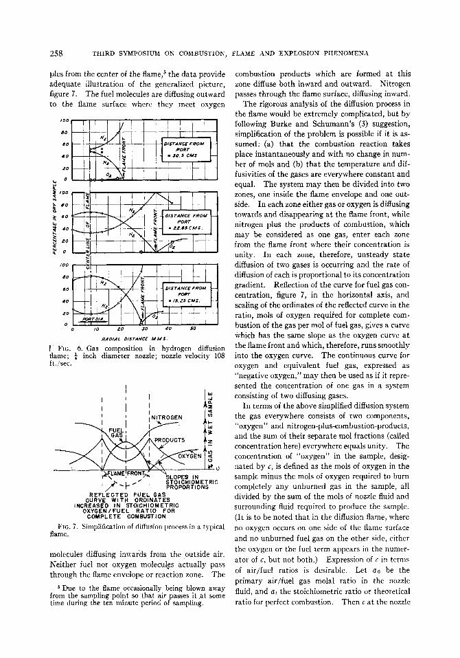
The process of diffusion occurring in a flame ofhydrogen leaving a port ¼ inch diameter a t avelocity of 108 ft./sec. 4 is illustrated in figure 6 ,
BUNDLE OF F 4 V~ ,@.
STRAIGHTENERS / BRASS I ,,
SCREEN ~ ~ I SCRd~N ~ ~ A .
I '/z" ~ [ 4 LENCTHS-~$~3; e'; ~°AND IZ" [ ~-Jl
4ALUMINUM F~OO ~OR ALI@NING , . le t
Z l / Z .~- I ~ , ~ " .
• , ~
$//; J E r
I~ xy~ u Z '~gl
or.--_ ~ ._ t
//8"ME TFIo. 4 . Details of rounded nozzles.
•s 1,l, ~ J/&"o~A. '//6" o.0. COPPER
TUBING 37~,D IA
, /-~ B R A S S ST#//=' -H ~-~}
DRILLED. 028•DIA.FITTED WITH $.S. NEEDLES
.015 *L O. pOg$"O. O., t/~."L ONG
• CALE I , , , I , , , I/ iNCH
Fro. 5 . Water-cooled sampling tube.
\\ 1 _ III I L
The samples were d rawn out simultaneously a n dstored in sample bottles to a w a i t analysis. Thet ime t a k e n to o b t a i n one b a t c h of seven s a m p l e swas approximately ten m i n u t e s ; a n d d u r i n g thist ime the gas a n d air flows were maintained s t e a d yu n d e r the action of pressure-regulating valves.This same apparatus was u s e d to a l i m i t e d extent
in w h i c h the analyses of s a m p l e s t a k e n across theflame a t three different.distances from the portare presented. I n spite of a s l i g h t unsteadiness,a n d the consequent appearance of oxygen in sam-
4Nozzle velocity is calculated a t room temperatureand pressure.
258 T H I R D S Y M P O S I U M O N C O M B U S T I O N , F L A M E A N D E X P L O S I O N P I I E N O M E N A
ples from the center of the flame, 5 the d a t a providea d e q u a t e illustration of the generalized picture,figure 7 . The fuel molecules are diffusing o u t w a r dto the flame surface w h e r e they meet oxygen
/ 0 0
DO
GO
4 0
2 0
O
~'°° F
/00
, e ; -
' d
8 0
6 0
4 0
2 0
o0 IO z o 30 4 0 5 0
RADIAl. D/STANCE A I M S .
[ FIG. 6 . Gas composition in hydrogen diffusionflame; ¼ inch diameter nozzle; nozzle velocity 108ft./sec.
, , [ ;JI il NITROGEN T
• .%. 0~ F ~ I J ~ E ' , F R O N T ~ % L O P E S I Nj ~," ~ L ~ " I S T O I D H I O M E T R I C//" T" P R O P O R T I O N S
R E F L E C T E D F U E L G A SC U R V E WITH O R D I N A T E S
i N C R E A S E D I N S T O I C H I O M E T R I CO X Y G E N / F U E L R A T I O FOR
C O M P L E T E C O M B U S T I O N
Fro. 7. Simplification of diffusion process in a typicalflame.
molecules diffusing i n w a r d s from the outside air.N e i t h e r fuel nor oxygen molecules a c t u a l l y passt h r o u g h the flame envelope or reaction zone. The
Due to the flame occasionally being blown awayfrom the sampling point so that air passes it a t somet ime during the ten minute period of sampling.
combustion p r o d u c t s w h i c h are formed a t thiszone diffuse both i n w a r d a n d o u t w a r d . Nitrogenp a s s e s through the flame surface, diffusing i n w a r d .
The rigorous analysis of the diffusion process inthe flame wou ld be extremely complicated, but byfollowing B u r k e and S c h u m a n n ' s (3) suggestion,simplification of the problem is possible if it is as-s u m e d : (a) that the combustion reaction t a k e splace instantaneously a n d with no change in num-b e r of mols a n d (b) that the temperature and dif-fusivities of the g a s e s are everywhere constant a n de q u a l . The system may then be d i v i d e d into twozones, one inside the f l a m e envelope a n d one out-side. I n each zone either gas or oxygen i s diffusingt o w a r d s a n d disappearing a t the flame front , w h i l enitrogen p l u s the p r o d u c t s of combustion, w h i c hmay be considered as one gas, e n t e r each zonefrom the flame front w h e r e t h e i r concentration isunity. I n each zone, therefore, u n s t e a d y s t a t ediffusion of two g a s e s is occurring a n d the rate ofdiffusion of each is proportional to i t s concentrationgradient. Reflection of the c u r v e for fuel gas con-centration, figure 7 , in the horizontal axis, a n dscaling of the ordinates of the reflected c u r v e in theratio, mols of oxygen r e q u i r e d for complete com-b u s t i o n of the gas per mol of fuel gas, g i v e s a c u r v eWhich has the same slope a s the oxygen c u r v e a tthe flame front a n d which, therefore, r u n s smoothlyinto the oxygen curve. The continuous c u r v e foroxygen a n d equivalent fuel gas, expressed a s"negative oxygen," may then be u s e d a s if it repre-sented the concentration of one gas in a systemconsisting of two diffusing gases.
I n t e r m s of the a b o v e simplified diffusion systemthe gas everywhere consists of two components,"oxygen" a n d nitrogen-plus-combustion-products,a n d the sum of their separate too l fractions (calledconcentration here) everywhere e q u a l s unity. Theconcentration of "oxygen" in the sample, desig-n a t e d by c, i s defined a s the mols of oxygen in thesample m i n u s the mols of oxygen r e q u i r e d to b u r ncompletely a n y u n b u r n e d gas in the sample, alld i v i d e d by the sum of the mols of nozzle f lu id a n dsurrounding fluid r e q u i r e d to produce the sample.(It is to be noted that in the diffusion flame, w h e r eno oxygen o c c u r s on one side of the flame surfaceand no u n b u r n e d fuel gas on the other side, eitherthe oxygen or the fuel term a p p e a r s in the numer-ator of c, but not both.) Expression of c in termsof a i r / f u e l ratios is desirable. Let a0 be theprimary a i r / f u e l gas m o l a l ratio in the nozzlefluid, a n d at the stoichiometric ratio or theoreticalratio for perfect combustion. Then c a t the nozzle

FLAMES OF FUEL JETS 259
is 0.21(a0 - a~)/(1 + a0); c a t the flame tip a n deverywhere else on the flame surface is 0 ; a n d c inthe ambient air is 0.21.
With the generalized "oxygen" content c of afuel-air system defined, it is desirable to expressconcentration dimensionlessly by defining theterm C,, a s
(c a t t i m e t o f l o w f r o m n o z z l e t o a n ys p e c i f i e d p o i n t a l o n g t h e a x i s of t h e
f l a m e ) - (c a t i n f i n i t e t i m e )Cm
( i n i t i a l c in n o z z l e f lu id ) - (c a ti n f i n i t e t i m e )
I t is seen that C~ is the unaccomplished fractionalchange in concentration, expressed a s a fractionof the total possiblc change from the v a l u e a t thcnozzle to the ultimate v a l u e a l o n g the flame axisat infinity. The v a l u e of C,, at the flame tip,called O , is given by"
0 - - .21C , , a t f l a m e t i p = C , = .21(ao - a~) - .21
1 + a 0
_ 1 + a 0 (1)1 - + - a t
For example, consider a methane flame b u r n i n gwith no primary air. Since one v o l u m e cf methaner e q u i r e s 2 volumes of oxygen for complete com-bustion, the equivalent "oxygen" concentrationin the pure methane a t the port is - 2 . 0 , a n d v a r i e sa l o n g the flame axis from - 2 . 0 through 0 at theflame tip on to +0.21 at an infinite distance. Thet o t a l possible change is 2.21, a n d the fractionalchange out to the flame tip is 2/2.21 = 0.905.The unaccomplished fractional change is 1 - 0.905= 0.095; this is C:.
The problem of diffusion in the simplified open-flame system just described is treated in the Ap-pendix. It l e a d s to a relation between the q u a n t i -ties, generalized concentration C,, and generalizedt ime 0 , defined a s follows:
0 = 4D,.t/D~-, (2)
w h e r e t = elapsed t ime for gas to flow from noz-zle to point w h e r e concentration is C~,,
D,. = molecular diffusivity coefficient forthe system,
D = nozzle diameter.The relation is
C , . = 1 - e-I/4° (3)
The v a l u e of o:, or 0 a t the flame tip, comes froma substitution from (1) into (3) to o b t a i n
1 + a o _ 1 - - e - 1 / 4 0 : (4)1 + a t
from which
O/ =1 ( s )
4 I n [(1 A- a , ) / ( a , - - at,)]
The next problem is to relate the t ime factor, 0 ,to the distance a l o n g the flame. I t is d e s i r e d toknow t:, the t ime of flow to the flame tip. Actuallythe flame length, L, was measured, not t:; henceo : must be expressed in t e r m s of L. Certain as-sumptions have therefore to be made as to thechange of gas velocity v , along the length of theflame so that O: may be evaluated from the ex-pression
fo 4D" foL dX (6)4 D J : _ 4D~ ': dl =O: = D " D" DT v
w h e r e v = the gas velocity at a distance x from thenozzle; i.e. the solution of e q u a t i o n 6 involves thedetermination of the relationship between v and x .The gas velocities used are very small and are de-creased by viscous d r a g a n d increased a s a r e s u l tof the density difference between the gas streama n d its surroundings.
Problems involving this b a l a n c e of viscous d r a gv e r s u s I)uoyancy are k n o w n to involve a d i m e n -sionless parameter due to Grashof, namely (Gr) =Dao~'~g.xt/u ~', w h e r e o , ~, g, tt a n d At are respectivelydensity, temperature coefficient of expansion,gravitational acceleration, viscosity, a n d tem-perature difference. The velocity v a t an5' point xa l o n g the flame axis s h o u l d then be expressible inthe dimensionless form
v _ .fi ( D a t ; 2 ~ g A t x )l" \ ~2 ' D ' a " , (7)
w h e r e I" is the nozzle velocity, a n d a0 is introducedbecause of its possible effect on combustion rateand consequently on the temperature pattern a n dresultant buoyancy. E q u a t i o n 6 may be writtenas
4D~ f ~ d xO: = 17-D~ Jo v / t : (6a)
The volumetric flow rate, Q, e q u a l s rVDZ/4 .M a k i n g this substitution in equation 6a, sub-stituting v / V from equation 7 , one obtains

260 T H I R D S Y M P O S I U M O N COMBUSTION~ F L A M E A N D E X P L O S I O N P H E N O M E N A
Qo: _ [ L dx~rDv Jo fz(Gr, ao, x/D)
= f2(L, D, Gr, ao) (8)
I f attention is f o c u s e d on a single primary a i r / f u e lratio a0 then, since all the fuel g a s e s on w h i c h d a t aare here available have a b o u t the same theoreticalcombustion temperature a n d p r o d u c e combustionproducts of a b o u t the same molecular weight, theonly q u a n t i t y in the Grashof n u m b e r w h i c h i s
monoxide flames are plotted a s Qo: v e r s u s flamelength L for different diameters a n d fixed v a l u e sof p r i m a r y a i r / f u e l ratio a0. I t will be noted thatthese d a t a , covering a 7-fold r a n g e of v a l u e s ofport d i a m e t e r D, fit c u r v e s of the form
L = A logzo Qo/ + B (10)
w h e r e A a n d B are independent of velocity a n dport diameter.
F u r t h e r evidence to s u p p o r t the generalizationthat L d e p e n d s on D a n d V only a s they affect
0 . 0 1
0 . 0 0 8
0 . 0 0 8
0 . 0 0 4
laJo 3
w o . o o 2n
I - -14.
D 0 . 0 0 1t~
0 . 0 0 0 80
0 . 0 0 0 6
0 . 0 0 0 4
O.O00Z
0 4 8 12 I S INCHES 20 2 4F L A M E L E N G T H
FIG. 8 . Correlation of data on lengths of diffusion flames.
2 8 3 2 3 6
variable in these experiments i s the d i a m e t e r D .I n addition, D , will be constant. Consequently,e q u a t i o n 8 becomes
Qa: = f3(L, D, ao) (9)
However, when experimental d a t a are s t u d i e d , La n d Q b e i n g m e a s u r e d a n d 0 / b e i n g calculated fromequation 5 , L is f o u n d to be a unique function ofQo:, a n d not dependent on the diameter D of thenozzle. This is illustrated in figure 8 , w h e r e someof R e m b e r t ' s (1) d a t a , the d a t a of G a u n c e (5) oncity-gas flames, a n d the a u t h o r ' s d a t a for carbon
flow-rate Q comes from other d a t a of R e m b e r t (1)g i v e n in t a b l e 1 . A t fixed v a l u e s of Q a n d a0, a3-fold variation in nozzle diameter is seen to pro-d u c e but a minor variation in flame length a tconstant Q.6
The dependence of L on Qol alone, and not onD , s u g g e s t s the need for imposing a limitation onthe general treatment that led to equation 9 . Ifin e q u a t i o n 7 the Grashof n u m b e r and x/D enter
6• There is some suggestion in the data, however,that at high primary air-fuel ratios (a0 = 2) the flamelength may decrease somewhat a s nozzle diameter in-creases, at constant Q.

FLAMES OF EUEL JETS 261
a s a p r o d u c t term (Gr)W3(x/D), then D disappearsfrom equation 7 , a n d consequently from e q u a t i o n8 , a n d equation 9 becomes
O0s =~,(L, a0), (1 l)
a relation seen to be consistent with the experi-mentally established relation 10.
Although equation 10 a p p e a r s to be a satis-factory form of the more general e q u a t i o n 11 inthe r a n g e covered by the d a t a , no d a t a were ob-t a i n e d a t flame lengths less than a b o u t 5 inches.(The experiments h a d been designed primarily forthe s t u d y of t u r b u l e n t flames, a n d the gas-measur-ing equipment was unsatisfactory at the extremelylow velocities necessary to produce s h o r t diffusionflames.) I n the region of extremely l o w nozzlevelocity it is unlikely that v / V varies much from
Values of the constants A a n d B of e q u a t i o n 10are given in t a b l e 2 , for L a n d Q h a v i n g the di-mensions, feet a n d cu. f t . per sec. a t room tem-perature a n d pressure. I t i s to be noted that u n -a e r a t e d c a r b o n monoxide has the same v a l u e of Aa s unaerated city gas.
R e m b e r t (1) obtained a n empirical equation forflame length, by plotting a n d cross-plotting hisd a t a , in the form
L ' = f(ao) log10 V
+ ,#(ao) logto D ' + ¢(ao) (13)
w h e r e L ' a n d D ' are in inches a n d V is in ft./sec.,a n d f , ~, a n d ¢ are three different functions of a0.The present analysis suggests that this s h o u l d bereducible to the form of equation 10 . This ispossible if ¢(a0) is d o u b l e f(ao). I t will be seen
T A B L E 1
Data of Rembert on city-gasf lame lengths(Each line of data corresponds to constant flow rate Q)
Q = lao = 0.5o.ooss i 1 .o
i 2 . 0
F l a m e l e n g t h , i n c h e s , when nozz l e diameter , i n c h e s , is:
0.28
16.511.6
0 36
20.116.010.9
0.47 0 6 1 i 0 82i
20.5 20.0 ' 20.315.1 - - 15.310.2 9.9 9.0
i!Average l e n g t h , Percent spread
i n c h e s a r o u n d a v e r a g e
20.215.710.3
+1+ 5 , --4
+12, --13
Q = 0.0021; ao = 0.5 10.9 10.5 11.7 10.0 - - 10.8 + 8 , - 7
Q = 0.0032;a~ = 0 22.4 21.3 22.1 - - 21.4 21.8 + 3 , --2
Q = 0.0034; ao = 1.29 - - 9.5 9.4 8.9 - - 9.3 + 2 , - 4
Air requirement of city-gas used, a~ = 4.8; M.W. = 14.7.
u n i t y before the flame tip is reached; hence e q u a -tion 6a l e a d s to the relation
L - V D 2 0 r - Qo: (12)4D,, lED
This approach of L to proportionality to Q a t lowv a l u e s of L is in accordance with the experimentalresults of B u r k e and S c h u m a n n (3). The d a t aare inadequate to permit accurate determinationof the point at which transition begins to o c c u rfrom equation 10 to equation 12, but figures 1 a n d8 are helpful. All the experimental d a t a pointsappearing on the diffusion-flame portion of thecurve of figure 1 fit fairly well the straight-linerelation appearing on figure 8 . Prediction byequation 10 of flame lengths less than six inchesis p r o b a b l y unsafe.
TABLE 2Values o f A and B in equation, L = .4 logtoQo/ + B
Gas A Bao
City gas 0 1.39 5.09City gas 1.29 1.87 5.93
Carbon monoxide 0 1.39 4.91
In calculation of Of, at = 2.38 for carbon monoxide;for city gas it varies with composition from 4.3 to 4.8.
from t a b l e 3 containing v a l u e s of the functions ofa0 in R e m b e r t ' s e q u a t i o n that q,(a0) is of the r i g h torder, except for a0 = 0.5. A comparison ofv a l u e s of L predicted by R e m b e r t ' s e q u a t i o n withhis own experimental d a t a indicates that hisrecommended v a l u e s of f ( a 0) a n d ¢p(a0) a t a 0 = 0.5

262 T H I R D S Y M P O S I U M O N C O M B U S T I O N ~ F L A M E A N D E X P L O S I O N P H E N O M E N A
were poorly chosen a n d predict an effect of d i a m -eter not supported by his d a t a in t a b l e 1; a n d thata b e t t e r set of v a l u e s do satisfy the condition¢(a0) = 2f(a0). I t appears, then , t h a t the presentrecommended equation 10 fits the d a t a a t l e a s ta s well a s the more complicated equation 13 .
Use of e q u a t i o n 10 to predict city gas diffusion-flame lengths a t other v a l u e s of primary a i r thanthose given in t a b l e 2 m a y be desirable. Rem-b e r t ' s data g i v e n in t a b l e 1 have been used to
TASL~ 3
Functions o f a o i n Rembert's equation
ao f ( a o ) ] ~(ao)
0 i 17.6 33.9i
0.5 i 23.3 32.61 2 3 . 5 4 3 . 02 21.6 i 39.0
~(ao)
25.218.914.08.6
g , O
o1,8
,2
to
1 , 4
/0 Z
/~ E M B E R T D A T A
0 - O • . 0 0 5 5
A - 0 " . 0 0 3 2
{I- Q - . 0 0 3 4• - 0 = . 0 0 2 1
• - FROM T H I SP A P E R ' , FIG. 8
I
L!
{:lo, P R / M A R ~ " A I R / F/../£L VOLUMETRIC R A T I O
FZG. O. Variation, with ¢10,of constant "A" of equa-tion 10.
calculate, for his various values of a0, the valuesof A which wou ld make equation 10 fit . The re-s u l t s of the calculation are presented in figure 9as .t v e r s u s a0. On the same plot a p p e a r the twovalues of A obtained by weighting all d a t a ap-pearing in figure 8 . The c u r v e d rawn throughthese two best established points is recommendedfor use u n t i l more data become available. I t isnot now k n o w n whether this c u r v e , w h i c h fits bothcity gas a n d carbon monoxide a t zero p r i m a r y air,fits the second gas at other v a l u e s of ao.
DII~FUSION F L A M E BIIIEAKDOWN
Although the experiments d e s c r i b e d a b o v e wered e s i g n e d primarily for s t u d y of mixing in flames,the associated transition phenomena from laminarto t u r b u l e n t flames were so striking that somemeasurements of break-point lengths were m a d ein the apparatus. These measurements were alsor e q u i r e d in the s t u d y of t u r b u l e n t flames b e c a u s ein some instances the length of flame froth nozzleto breakpoint was a n appreciable fraction of thet o t a l flame l e n g t h a n d i t was important to havemeasurements of the point a t w h i c h turbulentmixing commenced. I t i s to be understood thatthe conditions for s t u d y of the phenomenon werenot controlled to the extent accepted as b e i n gnecessary for the elimination of unknown tur-bulence so important in the s t u d y of laminar flowinstability.
° a¢ir~. a,lS, MOL w r le~ c,g" ¢ ~ o ~ c ~ OArA• O r r GAS, ~0¢ w r lJ~ sl,g aAUm:C~ oArA
• city ~As,~oL wr t~~ ,/d ~ c ¢ ~ OArA
• ! I i i
i
o it • a • s 6
or, so ,'r f sic
FIG. 10. Breakpoint lengths, hydrogen and city-gasflames (non-premix).
The f u r n a c e top was removed for these measure-ments, a n d in some c a s e s the secondary air wast u r n e d on to s t e a d y the flames. (I ts velocity wasapproximately 0.2 ft./sec.) Where observation ofthe breakpoint was difficult b e c a u s e of low flameluminosity, direct v i s u a l observation was supple-mented by examination of the s h a d o w p r o d u c e dby shining a n intense l i g h t from a single point-source through the flame onto a w h i t e screen.
The characteristic variation of break-pointlength with nozzle velocity is apparent in figure 1and in figure 10, w h e r e d a t a on hydrogen a n d citygas flames are plotted. A t some critical portvelocity in the region of transition from diffusionto t u r b u l e n t flame the breakpoint s t a r t s a t theflame tip (see figs. 1 a n d 2) a n d moves downt o w a r d s the port r a p i d l y with increasing portvelocity. At h i g h e r velocities breakpoint becomes

FLAMES OF FUEL IETS 263
relatively constant. The breakpoint was f o u n d tobe perfectly stable, and there was no random break-down from laminar to turbulent flow c a u s e d bydisturbances in the s u r r o u n d i n g air, except withthe very long diffusion flames from s m a l l ports inthe region of the critical velocity; s u c h flamesc o u l d be affected by clapping Of the h a n d s .
Experimental work on t u r b u l e n t jets of air a n dgas reported in the literature does not inc lude refer-ence to this break-point phenomenon. I t is evi-dent from a s t u d y of this work that the transitionfrom laminar to turbulent flow occurred very closeto the por t . I n work to be reported in a l a t e r p a p e ron t u r b u l e n t mixing in l iqu id jets it was found,however, that the break-point behavior of a s m a l ll iqu id jet was very similar to that s h o w n in figures1 or 10. This suggests that the phenomenon isrelated to fluid flow rather than to combustion,r e q u i r i n g interpretation in the case of flames int e r m s of the local physical factors such a s viscositya n d density in the f a m e .
As it is of importance to be able to predict inpractice the region in w h i c h transition from lami-n a r to turbulent flow occurs, all the d a t a availablehave been presented in Appendix II. The R e y n -olds n u m b e r s given there are in terms of the vis-cosity a n d density of the nozzle fluid a t room tem-perature. T~hat this is not the correct bas i s forcorrelation is c l e a r from the scatter of criticalv a l u e s obtained, and from the effect of v a r y i n gnozzle a n d surrounding fluid densities a n d viscosi-ties indicated in the results from l iqu id j e t s .F i g u r e 11 has, however, been constructed a s aguide to indicate approximately the region inw h i c h transition may be expected to occur. Thedifficulties normally associated with experimentala n d theoretical s t u d y of l a m i n a r flow instabilityeven in simple aerodynamic systems combinedwith the unknown variation in physical factorsdue to local heat release make any further s t u d yof the present d a t a fruitless.
A phenomenon of interest a n d possible practicalimportance connected with the break-point be-havior was observed d u r i n g the experimental w o r k .Over a certain r a n g e of port velocity it was possibleto o b t a i n two s t a b l e but different flames. Thefirst, or on-port flame, i s that a l r e a d y described,figure 1 , with ignition commencing a t the por t .I n the second, ignition occurred some short dis-t a n c e a b o v e the por t , a n d the flame was every-w h e r e t u r b u l e n t and shorter than the first flameby a distance almost e q u a l to the break-pointlength, figure 1 . This l a t t e r off-port flame c o u l d
also be obtained a t high port velocities, if a s m a l lpilot f a m e was u s e d to locate the ignition point .The striking reduction of total f a m e length a t t e n -d a n t on the l a t e r initiation of combustion is p r o b a -bly associated with the effect of local R e y n o l d sn u m b e r on break-point length. I f break-pointlength increases with decreasing port velocity (seefig. t ) it s h o u l d similarly increase w i t h increasinglocal viscosity. The hot mantle of f a m e a r o u n dthe jet a t the b a s e Of the on-port flame p r o d u c e sa high viscosity w h i c h d e l a y s initiation of t u r b u l e n t
" b
Xo¢I,om
z'(D( 3/oz>..b~nr
2-
4
5-
6-
7 -
8-
9-
I0-
HYDROGENZERO PRIMARY AIR
GITYGASZERO PRIMARYAIR
} G O - - Z E R O PRIMARY AIR
i}HYDROGENWITH PRIMARY[CITYGASAIR FWITHAIRPRIMARY
PROPANE Ji}AGETYLENEZERO PRIMARYAIR
FIG, 11, Values of Reynolds number (cold) at whichtransition from diffusion 1o turtmlent flames com-mences.
mixing. Accordingly, the total s p a c e r e q u i r e d forcombustion is less u-hen ignition is d e l a y e d to per-mit early transition to t u r b u l e n t flow. City gasoff-port flames were less l u m i n o u s than on-portflames, due p r o b a b l y to the earl)" aeration of theflame which r e d u c e d the thermal decompositionnormally occurring when gas is h e a t e d in the ab-s e n c e of air.
ENGINEERING APPLICATION
Although the relationships for flame length es-tablished are b a s e d on limited d a t a , the)" m a y be

264 THIRD SYMPOSIUM ON COMBUSTION~ FLAME AND EXPLOSION PHENOMENA
u s e d to estimate the s p a c e requirement for dif-fusion-flame combustion u n d e r conditions of freeaccess of atmospheric air. As a n example of use,let the problem a t h a n d be the estimation of flainelength when n a t u r a l ga s is b u r n i n g in an un-restricted air s u p p l y , i s s u i n g a t a velocity of tenfeet per second from a quarter-inch por t . T oe n s u r e this is o u t s i d e the transition region theR e y n o l d s n u m b e r i s required. A s s u m i n g the gasis p u r e methane, the viscosity a t 6 0 ° F . is 108 ×10-6 poises o r 7.25 X 10-e fps u n i t s ; the density a t60°F. is (16/359) X (492/520) = 0.0422 ib./cu.ft.;whence the R e y n o l d s n u m b e r is 10 X (0.0422/7.25X 10-6) X (1/48) = 1,210, i.e. well b e l o w thecritical range. The volume flow rate Q is 10(~r/4)(})~ x 144 = 0.0342 cu. ft./see. The primarya i r / f u e l ratio a0 is zero. The theoretical volu-m e t r i c a i r / f u e l r a t i o for complete combustion, a t ,b a s e d on the assumption that the fuel is puremethane, is 2 X (100/21) = 9.52. The v a l u eCh from equation 4 , is (1 + 0 ) / ( 1 + 9.52) =0.095. From equation 3 , CI = 1 - e-1/4°I, orOf = 1 / ( - - 4 l n ( 1 -- C:)) = 1 / ( - 4 X 2.303 Xlog10 0.905) = 2.7. From figure 9 or t a b l e 2 ,A a n d B a r e estimated a s 1.4 a n d 5.0. Then
L = A loglo (Qoj) + B
= 1.4 logi0 (0.0342 X 2.7) + 5.0
= 2.15 f t . = 26 inches.
Use of this method of estimating diffusion flamelength m u s t at present be restricted to those fuelg a s e s for w h i c h A a n d B can be estimated; theseconstants are presumably dependent on g~s densitya n d a i r requirement a ,
APPENDIX I
F o r the cylindrical system described in the textthe diffusion equation is:
Oc _ D~ ( 02c l Oc)ot \on"- + ~ ~ (a)
w h e r e c = the concentration of oxygen or thenegative oxygen equivalent of the com-b u s t i b l e gas (defined more completelyin the text),
y = r a d i a l distance from the axis of theflame,
t = elapsed time,D , = molecular diffusivity coefficient for the
system.P u t t i n g Y = 2y/D, w h e r e D -- diameter of the
por t , a n d a s s u m i n g D , is constant, equation 1 be-comes
OC O~C 1 OC- + - - - (2)
O0 OY2 Y OY
where 0 = 4Dd/D~ a n d
(c a t t i m e t o f l o w f r o m p o r t t o a n ys p e c i f i e d p o i n t in t h e f l a m e )
- (c a t i n f i n i t e t i m e )C =
( i n i t i a l c in n o z z l e f lu id )- (c a t i n f i n i t e t i m e )
The relation 2 is dimensionless a n d has the b o u n d -ary conditions (see fig. 7) :
OC/oY = 0 when Y = 0 a n d Y = ~c;
a n d when 0 = 0 , C = 1 from Y = 0 t o ± 1 a n dC = 0 f r o m g = ± 1 to ± c o .
A solution of equation 2 is
C = i e-X2e'J°(XY)'J~(h)'dh' (3)
where J0 a n d J i are zero- and first-order B e s s e lfunctions, respectively.This satisfies the b o u n d a r y conditions for oC/OY.Also, when 0 = 0 ,
/ a
C = ] Jo(XY)Jl(X).dX = 1 w h e n y2 < 1./0 = ½ w h e n Y 2 = l
= 0 w h e n y : > 1
(see page 78 of ref. 4).When Y = 0 , J0(XY) = 1 a n d the axial concen-
tration is given b y :
C,, = fo e-X2°Jl(X)'dX (4)
N o w
J r ( X ) = } - ( x / 2 ) ] + (X/~2)-52 2! 2 ! 3 !
(5)+ . . . ( - D r ( x / 2 ) :r+l
r!(r + 1) !
a n d since
i ® r !e-x2° X2r+l dX - 2 0 , + l ( 6 )
C , , = ~ ( - 1 ) r0 (r + U ! ( 4 0 ) ' + ' (7)
= 1 - - e- 1 1 4 0

FLAMES OF FUEL JETS 265
APPENDIX II
Experimental data on transition from diffusionto t u r b u l e n t flames.
(1) Hydrogen; zero primary air; viscosity 90 ×10-e poises a t 20°C.; nozzle gas d e n s i t y rela-tive to air .0693.
Nozzle Nozzle Reynoldsnumber (roomdiameter temperatureand pressure)
wh~ s/D is25 10 5
!8 inch 2160 3230 3640inch - - 2800 4600
¼ inch 1910 2600 - -
(2) Hydrogen; with p r i m a r y a i r
Nozzlediam:eter,inch
A
a0 = 0.2= 131X10-6
poises
~ela- Re whent i v e s /D isJ e n -s i t y L a r g e 25
.22; 7380 8340
.22~ - - 7800
.25( 5550 6690
a6 = 0.4= 147 × i0-e
Rein- Re when s/D istiveden-sity Large 100 50
.33 8270 - - 9630
.335 6200 - - 6350
.35O 7630
25
7700
ao = 0.6t* = 156 X 10-6
Re when s/D isR e l a t i v edensity
.403•422•432
L a r g e 100 50 25
7850 8650 - - - -6180 - - 7480 11,5006400 - - - - 8,250
(3) City gas : zero p r i m a r y a i r ; viscosity 140 ×10- e poises a t 20°C.; nozzle gas d e n s i t y rela-tive to a i r = 0.69.
N o z z l ed iame te r R e when s /D i s :
Large 25 10 5
inch 3720 5740 11,700 16,700inch 3380 4280 8,260 11,400inch 3980 4380 6,630 10,900
(4) City gas : with primary air; ¼ inch nozzle:
ao R e l a t i v e I V i s c o s i t y , p o i s e sd e n s i t y
.54 .715 [ 150 X 10-~
.84 •762 153 X 10~1.61 [ .832 l 158X 10--*
when s /D i s
50 25
6,200 8,3008,340 10,350
12,000
(5) C a r b o n monoxide; zero primary air; viscosity170 X 10- s poises; nozzle gas d e n s i t y rela-tive to a i r 0.967; [ inch d i a m e t e r nozzle.
when s / D is large, R e = 4,75025 , R e = 5,35010 , R e = 7,050
(6) Propane; zero p r i m a r y air; viscosity 82 × 10-8poises; d e n s i t y relative to air 1.49; t inchnozzle diameter•
when s /D is 25 , R e = 10,400(7) Acetylene; zero primary air; viscosity 93 X
10-6 poises; density relative to air 0.9; t inchnozzle diameter.
when s /D is large, R e = 8,90025 , R e = 12,50010 , R e = 33,100
(8) Cold air j e t s . D a t a from experiments withinch a n d ~ inch nozzles indicate that s /D
is I0 or less when the R e y n o l d s n u m b e r is2,500.
(9) L iqu id j e t s ; nozzle d i a m e t e r .041 inch.
Nozzle fluid vis-cosity centi-poises . . . . . . . . . .
Surrounding fluidviscosity, centi-poises . . . . . . . . .
when s /D is10, Re = . .5 , Re = . .
Density relative to surrounding fluid
1 • 1 1
1.16 1.46 2.61
1.05 1.46 1.05
1400 2000 5202440 3200 2050
, . o ~ i , o . 9 I o . 8 2
/
1.54 1.54 1.5411.54
I1.54 1.54 1.54 1.54
1340 19413 1900 19402860 310~ 3060 - -
D, DtD~
gGr
J0, ]~L, L '
Q
TABLE OF NOM:ENCLATURE
A, B = constants in equation 10a0 = mols. primary air/mol, fuel gasa~ = air required for complete combustion of one
real of fuel gasc = concentration of oxygen or the negative oxy-
gen equivalent of the combustible gasC = (c at a given p o i n t - c at infinite time)(initial
c -- c a t infinite time)= nozzle diameter, feetand inches, respectively= coefficient of molecul~ar diffusivity, ft.2/sec.= acceleration due to ~ravity= Grashof's number = D3ml3gAt/t,2= Bessel functions c,i zero- and first-order= flame length, feet and inches, respectively= rate of flow from nozzle, ft.3/sec. (room temp.
and press.)s = distance from break-point to por t , f t .t - elapsed time, sec.v = gas velocity along the axis of the flame, ft./see.

266 THIRD SYMPOSIUM ON COMBUSTION~ FLAME AND EXPLOSION PHENOMENA
V = nozzle velocity (room temp. and press.),ft./sec.
x = distance from nozzle along axis of the flame,ft.
3' = radial distance from axis of the flame, f t .Y = 2y/Do = 4D,t /D2p = density of gas
= coefficient of expansion of gasAt = temperature difference. = viscosity of gas
Subscripts m a n d f = value of C, 0 , and t on the flameaxis and at the flame tip.
REFERENCES
1. REMBERT, E. W., AND HASLAM, R. T.: Ind. andEng. Chemistry, 17, 1236 (Dec. 1925).
2 . CUTHBERTSON, J.: Journal Society Chemical Ind.Trans., 50 , 451-457 (1931).
3 . BURKE, S., AND SCItU~rAI~, T.: Ind. EngineeringChemistry, 20 , 998-1009 (1928).
4. GRAY, MATTHEWS, AND MACROBERT: A Treatiseon Bessel Functions and Their Applications toPhysics. Macmillan (1931).
5. GAUNCE, a . : Unpublished research at M.I.T., 1939.
31
M I X I N G AND C O M B U S T I O N IN TURBULENT GAS JETS t
B y W . R. HAWTHORNE, 2 D. S. WEDDELL, s AND H. C. HOTTEL4
ABSTRACT
Vis ib le flame lengths a n d concentration patternshave been obtained in t u r b u l e n t jets of flameformed by combustible gas i s s u i n g from circularnozzles into s t a g n a n t air. The nozzle velocitiesw e r e a b o v e t h o s e which, in a previous paper, weref o u n d necessary to i n s u r e that the m i x i n g s h o u l dbe turbulent. A s a bas i s for analysis of the d a t aa simplified treatment is presented for mixing ofnozzle a n d a m b i e n t f lu ids in a vertical jet . Thesimplifying assumption of constant velocity a n dcomposition in a cross-section normal to the axisof flow is combined with a force-momentum bal-a n c e , continuity, a n d the perfect ga s laws to ob-tain a relation b e t w e e n mean concentration a n djet spread. The relation allows for initial differ-ence in density of nozzle a n d a m b i e h t streams,d e n s i t y variation due to combustion, a n d b u o y -ancy. The qualitative agreement b e t w e e n thea n a l y s i s a n d the experimental d a t a o n visible flamel e n g t h s a n d a x i a l concentration patterns indicatesplainly that the process of mixing resulting fromt h e momentum a n d buoyancy of the jet i s thecontrolling factor in determining progress of thecombustion. For free flames in w h i c h the effects
1 From theses submitted in partial requirementfor the degree of Sc.D. by W . R. Hawthorne, 1939,and by D. S. Weddell, I941.
Westinghouse Professor of Mechanical Engineer-ing, Massachusetts Institute of Technology.
3 At present with Monsanto Chemical Company.4 Professor of Fuel Engineering, Massachusetts In-
stitute of Technology.
of b u o y a n c y are small (high nozzle velocity, s m a l ldiameter) the analysis l e a d s to the following simplerelation for the l e n g t h of free t u r b u l e n t flame j e t s :
L I D = ~ r O r + ( 1 - C T )
w h e r e L = visible flame l e n g t hD = nozzle d i a m e t e rT r = a d i a b a t i c flame temperature, ab-
• soluteTN = a b s o l u t e temperature of nozzle
f lu idM s , MN = molecular w e i g h t s of surround-
i n g a n d nozzle fluids, respec-t i v e l y
C r = mol fraction of nozzle f lu id inthe u n r e a c t e d stoichiometricmixture
a r = mols of reactants/mols prod-u c t s , for the stoichiometricmixture.
I t is to be n o t e d that fuel gas flow rate is no factor,a s long a s it i s g r e a t e n o u g h to p r o d a c e a turbulentjet . Although d a t a for testing this relation cov-ered the s m a l l r a n g e of port diameter of 0.12 to0.30 inches, a wide variety of f u e l s was s t u d i e d , in-c l u d i n g propane, acetylene, hydrogen, carbon mon-oxide, city gas, mixtures of c a r b o n dioxide withcity gas, a n d mixtures of hydrogen with propane.T u r b u l e n t flame l e n g t h s v a r y i n g from 40 to 290nozzle d i a m e t e r s a r e predicted w i t h a v e r a g e a n d


