59
Flat Plate MBRs – A Viable and Proven Technology Scott Kafka, P.E. Hamlett Environmental Technologies Co. Title 22
Flat Plate MBRs – A Viable and Proven Technology
Scott Kafka, P.E.
Hamlett Environmental Technologies Co.
Title 22

MBR Fundamentals What is an MBR System?
2
• Membrane Biological Reactor System, or MBR
• Suspended growth activated sludge and low-pressure membrane filtration
• Sum of associated process basins, membrane trains and ancillary equipment (e.g. air scour and membrane cleaning)
Membrane Bioreactor Submerged membranes filter mixed liquor through
multiple barriers (membrane + biofilm)

Early Stage
• 1969 – U.S. Patent 3,472,765 issued to
Dorr-Oliver for Membrane Separation in Biological Reactor System Concept
• 1989 –Submerged MBR Development
• Early 1990’s –Submerged membranes developed and commercialized in North America and Japan
• Mid 1990’s – 60 installed MBRs in Japan
• Late 1990’s – First North American submerged MBR installations
MBR Technology Development Timeline

Today
• Exponential growth since the 1990’s
• MBR Systems reliably meet tight Bionutrient Removal (BNR) limits, in a small footprint
• Proven, Best Available Technology (BAT) for wastewater treatment
• Reuse, Recycle, Reclaim
Future
• “MBR Technology is the future of wastewater treatment as costs come down and energy efficiency improves”
• MBR technology for Wastewater reclamation and Water reuse, essential component of sustainable water management
MBR Technology Development Today and Future

MBR at a Glance Mature, growing
5
6,000+ MBRs Worldwide 600+ US MBR Installations 20+ Years of Experience
“A decade ago the largest MBR in the World was just under 3.4 MGD…(Judd, 2010)”

MBR Experience MBR Systems
Municipal, Tribal, Commercial and
Industrial Applications
Decentralization
Reuse Including RO Pretreatment
Retrofit
Biological Nutrient
Removal (BNR) 6

Why MBR? Benefits
7
• High quality effluent
• Small footprint
• Ease of operation
• Reliability
• Lower total cost
MBR Facility Hampton Creek WRF, GA

Why MBR? MBR is considered Best Available Treatment (B.A.T)
MBR Permeate Quality
Parameters Typical Values
Achievable Values
BOD5 < 2.0 mg/l Non-Detect TSS < 2.0 mg/l Non-Detect
Ammonia (NH3) < 1.0 mg/l Non-Detect
Total Nitrogen (TN) < 10.0 mg/l < 3.0 mg/l
Phosphorus (TP) < 1.0 mg/l < 0.03 mg/l
Turbidity < 0.10 NTU <0.05 NTU
Fecal Coliform < 2.2 CFU/100ml Non-Detect SDI < 3 <2
8
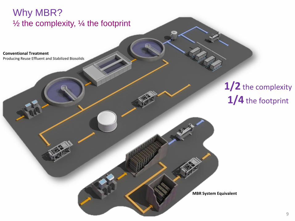
1/2 the complexity
1/4 the footprint
Why MBR? ½ the complexity, ¼ the footprint
9
Conventional Treatment Producing Reuse Effluent and Stabilized Biosolids
MBR System Equivalent

Technology Overview How much of what is removed?
mm 0.001 0.01 0.1 1 10 100 1,000
RO UF Particle Filtration
NF MF
Sand
Virus Bacteria
MBR
• UF and MF perform the same in submerged MBR applications. • Non-detect total suspended solids (TSS) and < 0.05 NTU.
• 106 bacteria removed w/o post-disinfection.
• 104 viruses removed w/o post-disinfection.
• Does not remove salt.
Salt
10

Technology Overview Harmful pathogens are physically rejected, filtered
11
Hepatitis Salmonella Crypto
< 1mm
< 10mm
< 100mm
0.01mm
Pore Size
CAS Effluent = 105 Fecal Coliforms
MBR Effluent = Non-Detect Fecal Coliforms

Technology Overview MBR Systems are comprehensive solutions
Stormflow Management
12
Biosolids Handling
Wastewater Treatment

MBR System Basic MBR System Process
13
• Activated Sludge Process
• Process selection and biological configuration depend on treatment objectives (e.g. TN , TP)
• For the same biomass inventory, the biological volume and footprint will be smaller. MBRs typically operate at 8,000-14,000 mg/L MLSS concentration

Technology Overview Membrane Biological Reactor
14
• A Membrane Biological Reactor is “one part” of a biological process where: • Small microbes degrade dissolved pollutants
• Air mixes the tank, provides oxygen and scours membranes for cleaning
• Water (permeate) is filtered through submerged membrane units or SMU; recycle mixed liquor returns to the process
• Rejected solids form biofilm that determines sustainable flux and plant hydraulics
Module Cassette MBR

MBR System Sub-Systems for a Fully-Functional WWTP
• Headworks
Fine Screens
Piping, Valves, Instrumentation
• Process Basins
(Anaerobic, Anoxic/ Post-Anoxic)
Mixers, Pumps
Piping, Valves, Instrumentation
• Aeration Basins
Fine Bubble Diffusers
Piping, Valves, Instrumentation
• Recycle System
RAS Pumps
Piping, Valves, Instrumentation
• Permeate System
Pumps
Piping, Valves, Instrumentation
• MBR Basin
Membrane Units
Piping, Valves, Instrumentation
• Aeration System (MBR, Pre-aeration)
Blowers
Piping, Valves, Instrumentation
• Chemical Cleaning
Mazzei Injector
Piping, Valves, Instrumentation
Chemicals
Sodium hypochlorite, oxalic acid or
citric acid
• Controls and Integration
PLC, SCADA, MCP
Hardware and software

Technology Overview Membrane Technology for MBR Systems
• RO & NF = High Pressure
• UF & MF = Low Pressure
• External & Submerged Membranes
• FS & HF for MBR
• Different flavors of each
• Focus on FS technologies

Technology Overview Membrane Technology – Flat Sheet, Flat Plate, Hollow Fiber, Spiral Wound
Hollow
Fiber
Flexible Flat
Sheet
Spiral
Wound
Flat
Plate

Technology Overview Membrane Configurations - Membrane Units
Flat Plate Flat Sheet
18
Hollow Fiber Spiral Wound

Manifold
Membrane Case
Membrane Cartridges
Diffuser Case
Diffuser
Tubes
19
Flat Plate Configuration Membrane Unit Components

Flat Plate Configuration Membrane Data
• Membrane sheet made of chlorinated polyethylene
• Nominal pore size 0.4 µm, effective pore size 0.2 µm
• ABS (Acrylonitrile Butadiene Styrene) support plate with a spacer layer between it and an ultrasonically welded flat sheet membrane on both sides
• Effective filtration area (varies): 8.6 –15.6 ft2 per cartridge; 107.64 ft2 per module
• Membrane Area (varies depending on model): 3,444 ft2/unit; 6,231 ft2/unit; 4,306 ft2/unit
Nozzle
Panel
Spacer
Membrane
Sheet
20

Flat Sheet Configuration Membrane Unit Components
21
Lifting Bars
Flat Sheets
Diffuser Assembly
Physical Characteristics Dry weight 1,764 lbs
Wet weight 2,425 lbs
Length 5.9 ft
Width 3.8 ft
Height 9.1 ft
Area per module 4,306 ft² (400 m²)
Base
Permeate Conn.
Cassette
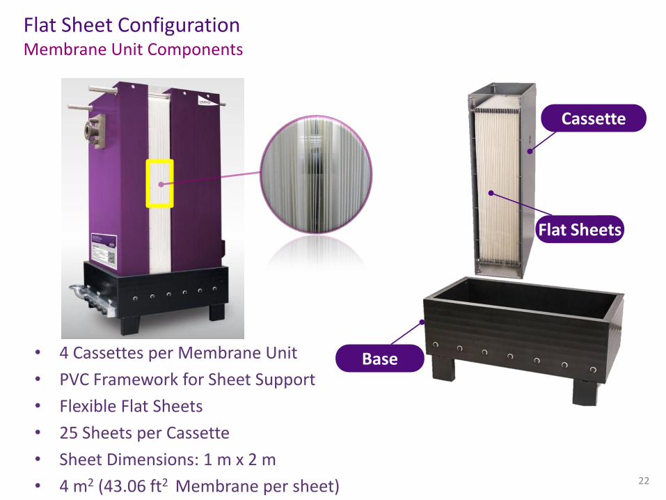
Flat Sheet Configuration Membrane Unit Components
• 4 Cassettes per Membrane Unit
• PVC Framework for Sheet Support
• Flexible Flat Sheets
• 25 Sheets per Cassette
• Sheet Dimensions: 1 m x 2 m
• 4 m2 (43.06 ft2 Membrane per sheet)
22
Cassette
Base
Flat Sheets

23
Flat Sheet Configuration Membrane Sheets

24
Flat Sheet Configuration Membrane Data
Factor Description
Pore Size 0.04mm
Type Hydrophilic
Material Polyethersulfone (PES)
Spacer Material Polyester
Fouling Potential Low
Chem./Mech. Stability High
Other Self Healing
(“Bullet Proof”)
Max. Warranty Period Lifetime

Flat Sheet Configuration How it works
Membrane
Permeate spacer
Laminary composite
Permeate removal
Guide plate
2 mm 8 mm 2 mm
Permeate Flow Solids are filtered out,
rejected by the membranes
(and biofilm). Permeate
moves through the plenum to
common manifold and drawn
out under vacuum

26
Flat Sheet Configuration Bullet Proof
0
0.1
0.2
0.3
0.4
0.5
0.6
0.7
0.8
0.9
1
30 60 90 120 150 180 210 240
NTU
Time (sec.)
Turbidity Data
Scratch
Cut edge
Bullet hole
Intact membrane sheet ( 0.04 NTU )
Self-healing Membrane Sheets
Turbidity trends show recovery after being
scraped, cut and punctured. Because of design, maximum
self healing in roughly 3 minutes.

27
Flat Plate Fouling
Organic Fouling

28
Flat Plate Fouling
Inorganic Fouling Causes:
- High Hardness/Iron levels in the
background water
- FeCl3 addition for Phosphorus
removal

29
Flat Plate Cleaning System

Technology Overview Biosolids Treatment with Flat Sheet/Flat Plate Membranes
Digester 1
Digester 2
Anoxic
Basin
MBT
Membrane Thickening Aerobic Digestion Process (MBT), utilizes flat sheet or flat plate membranes for thickening waste activated sludge (WAS).
• Reliably thickening sludge up to 4% solids concentration without adding polymers
• Provides Class B stabilized sludge in a reduced tank footprint
• Reducing sludge holding costs

Aerobic Digestion with Membrane Thickening (PAD®-K) - Dundee, MI
Membrane Thickener (MBT) - Woodside, NY
Membrane Thickener (MBT) – Westford Acton, MA
Technology Overview Biosolids Treatment with Flat Plate/Flat Sheet Membranes
Membrane Thickener (MBT) – Cayce, SC

Technology Overview Stormflow Management
Spiral wound ultrafiltration membranes can be utilized for a physical/chemical side-stream treatment of peak flows (stormBlox™), in lieu of biological treatment.
• Provide TSS, BOD, and COD removal • Alum injected into raw influent to enhance filterability
and contaminant removal • Utilizes iSEP™ flat-sheet, spiral wound, PVDF, ultra
filtration membranes (0.03 micron pore size) • Vacuum driven • Require periodic cleaning
• Improves reduction of soluble BOD • Works by adsorption • Spent media to be replaced disposed of in landfill
Activated Carbon BOD Removal
Ultrafiltration TSS Removal
Zeolite Ammonia Removal
• Naturally occurring mineral • Works by ion exchange with ammonium

Technology Overview Stormflow Management
Santa Lucia Preserve, CA (MBR + stormBlox™)
• Retrofit of an existing 0.05 MGD trickling filter • Upgrade included MBR + stormBLOX™ • StormBLOX System (71,000 GPD)
• Membrane skid (8ft x 10ft) • GAC media bed • 2 pumps, control valves • Alum addition
• MBR System (50,000 GPD) • Qty. 2 SMUs (RM150, KUBOTA®)

Michigan Flat Plate MBR Systems
Michigan Case Studies
- Dundee, MI
- Leoni, MI
- Odawa Casino, MI
- Gun Lake Casino, MI
34

Dundee, MI
35
Retrofit SBR tank = Pre-Air Tank
Covered MBR Tanks
Design Avg Q = 1.5 MGD
July 2005 Start-up
Pumped Permeate

Dundee, MI – PAD(K)
36
Aerobic Digester
Membrane Thickener

Dundee, MI
37

Leoni Twp., MI
38
Design Avg Q = 3.0 MGD
June 2010 Start-up Gravity flow Permeate with Pump Assist

Leoni, MI
39
Pre-Air Tank
Anoxic Tank
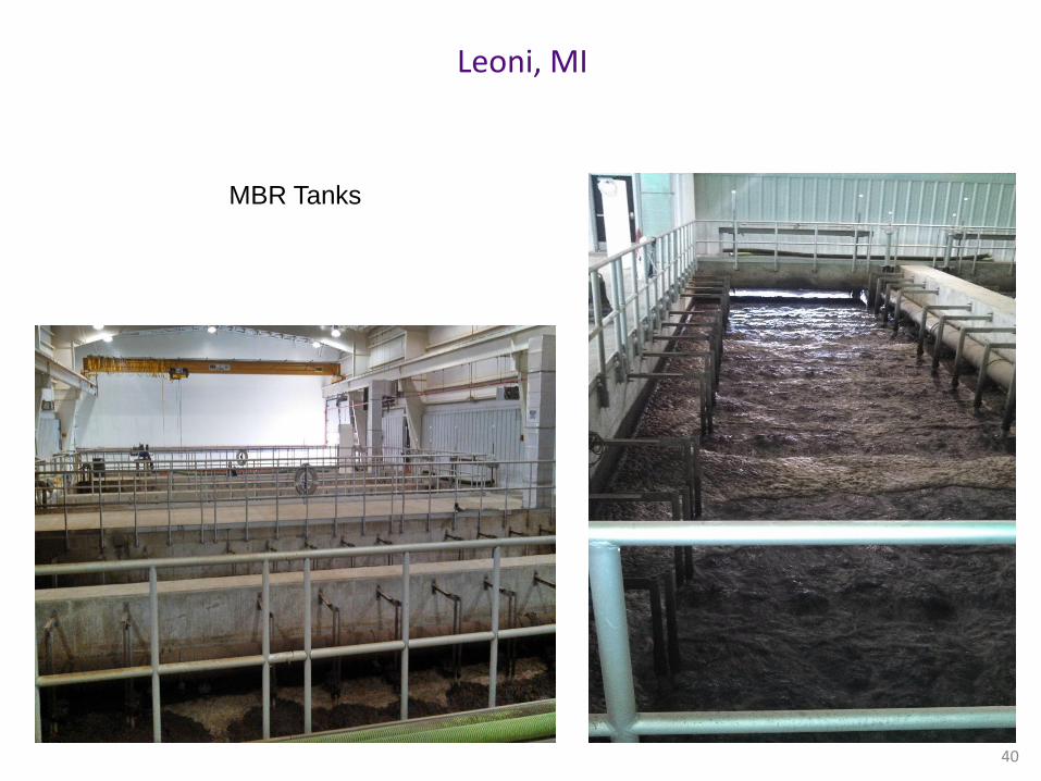
Leoni, MI
40
MBR Tanks

Leoni, MI
41

Odawa Casino Petoskey, MI
42
Entire Treatment Plant is
located in building
June 2008 Start-up
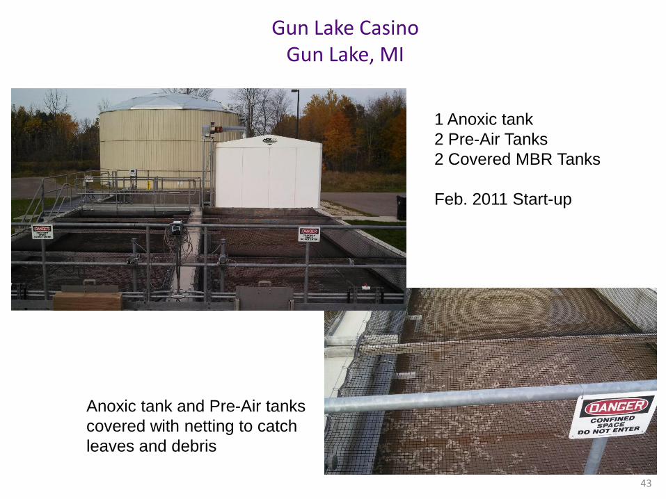
Gun Lake Casino Gun Lake, MI
43
1 Anoxic tank
2 Pre-Air Tanks
2 Covered MBR Tanks
Feb. 2011 Start-up
Anoxic tank and Pre-Air tanks
covered with netting to catch
leaves and debris

MBR Case Studies
1. Upper Wallkill, NJ 2. Pembroke, MA 3. Callao, VA

Case Study: Upper Wallkill, NJ MBR process achieving TN<3 mg/l for reuse at low influent temp (6° C)
• Original facility built in 1984
• Serves Franklin, Hamburg and Sussex boroughs
• Surface Water discharge (DSW)
• Actual flow 1.5 MGD; permitted for 3.0 MGD
• Permit NH3< 1mg/l, TP < 1 mg/l
45
Existing Facility

Case Study: Upper Wallkill, NJ Expansion/Upgrade Project • In 2005-06, Cerenzio & Panaro Consulting Engineers evaluated the plant expansion
to provide service to Vernon Town Center and Mountain Creek Development. Additional flow of 0.265 MGD
• Actual flow was 1.5 MGD compared to 3.0 MGD permitted flow but all the allocations were done, so a new Ground Water Discharge permit had to be issued
• Ground water discharge (DGW) and has to be replenished in the same area where the wastewater was received from
• Evaluated three options: • CAS (initial design)
• Use existing plant and aeration basin 3
• Add a Primary and Secondary Clarifier
• Add a Denitrification Filter/Ultraviolet Disinfection Building
• CAS (Alt “A”)
• Add a new independent CAS Plant, aeration basin 4
• Add a Denitrification Filter/Ultraviolet Disinfection Building
• MBR (Alt “B”)
• Add a new MBR system
• With little or no additional treatment, spray irrigation could be accommodated if it becomes desirable
46

Case Study: Upper Wallkill, NJ Evaluation of Estimated Construction Costs – Technology Comparison
47
CAS MBR Item (Alt "A") (Alt "B")
Mechanical Screen $160,000 $160,000
Rate Controller $65,000 $90,000
Pretreatment $372,000
Primary Clarifier $510,000
Primary Sludge Pump Station $275,000
Existing P.C. Pump Station $15,000 $15,000
Pipe Interconnection AB No.3
Aeration Basin No. 4 $1,425,000
Mix Chamber/Distribution Box $195,000
Final Clarifier (DGW) $555,000
Filter/UV Building $1,275,000
Reactors/Membrane Building $2,700,000
Site piping, Other Civil $375,000 $325,000
Sub-Total $4,850,000 $3,662,000
Contingency @ 5% $242,500 $183,100
Sub-Total $5,092,500 $3,845,100
Adjust for ENR CCI - 7660 $5,111,612 $3,850,643
Final Clarifier (DSW) $1,200,000 $1,700,000
Total $6,311,612 $5,550,643

Case Study: Upper Wallkill, NJ 0.265 MGD MBR System
48
Influent Characteristics
Parameters Typical Values (mg/l)
BOD5 200
TSS 260
TKN 45
Total Nitrogen (TN) 45
Phosphorus (TP) 8
Design Effluent Quality Parameters Typical Values
(mg/l)
BOD5 < 9.5
TSS < 2.2
TKN -
Total Nitrogen (TN) < 7
Phosphorus (TP) -
Design Parameters:
• Four Stage Process Design • Design flow: 0.265 MGD • No Peak Flows • Min Temp: 5.6 ° C • Max MLSS: 18,000 mg/l • No Carbon addition
MBR (Membrane Zone) Design
Filtration Mode: Pumped # of Reactors: 2
Submerged Membrane Unit (SMU):
ES200, KUBOTA®
# SMU: 16 Design Flux: 9.7 gfd
Minimum Temperature: 5.6°C Peak Factor: 1.0
# of Maintenance Cleans: 2

Case Study: Upper Wallkill, NJ 0.265 MGD MBR System
49
• Construction started in • May 2008; commissioned
in Jan 2010 • Serves Vernon Town
Center and Mountain Creek development
• Ground Water discharge (DGW)
• Permitted for 0.265 MGD; actual flow ~0.2 MGD
• Effluent pumped back up 6 miles to Vernon leach fields
• Permit TN<10 mg/l, Fecal coliforms <200/100ml
MBR System

Case Study: Upper Wallkill, NJ 0.265 MGD MBR System
50
Pre-Anoxic | Pre-Air | Post - Anoxic | MBR

Case Study: Pembroke, MA Single Stage MBR process technology achieving TN<10
• Retrofit of trickling filtration system
• Located in a suburb of South Boston, serves 3 commercial shopping plazas and an office building
• Existing facility design flow: 40,000 GPD MMF
• Original facility was built in 2006
• Permit BOD<30, TSS<30, TN < 10 mg/l
51
Existing Facility
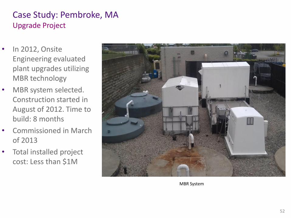
Case Study: Pembroke, MA Upgrade Project
• In 2012, Onsite Engineering evaluated plant upgrades utilizing MBR technology
• MBR system selected. Construction started in August of 2012. Time to build: 8 months
• Commissioned in March of 2013
• Total installed project cost: Less than $1M
52
MBR System

Case Study: Pembroke, MA 40,000 GPD MBR System
53
MBR System Layout
A single-stage MBR process utilizes saturated oxygen technology to satisfy process aeration requirements and eliminate the need for fine bubble diffusers. In addition, the process operates at an increased MLSS concentration and uses simultaneous nitrification/denitrification, the combination of which further intensifies the biological process into a significantly smaller footprint.

Case Study: Pembroke, MA 40,000 GPD MBR System
54
Influent Characteristics
Parameters Typical Values (mg/l)
BOD5 400
TSS 300
TKN 60
Total Nitrogen (TN) 60
Phosphorus (TP) 8
Design Effluent Quality Parameters Typical Values
(mg/l)
BOD5 <30
TSS <30
Total Nitrogen (TN) < 10
Design Parameters:
• Single Stage Process Design (microBLOX™)
• Design flow (MMF): 40,000 GPD
• No Peak Flows
• Min Temp: 10 ° C; Max Temp: 25 ° C
• Max MLSS: 25,000 mg/l
MBR (Membrane Zone) Design
Filtration Mode: Gravity # of Reactors: 1
Submerged Membrane Unit (SMU):
RM200, KUBOTA®
Supplemental Aeration Technology:
Oxygen concentrator + IR loop + Injector
# SMU: 2
Design Flux: 6.41 gfd Peak Factor: 1.0
# of Maintenance Cleans: 2

Case Study: Callao, VA MBR System Retrofit
• Retrofit of MBR system
• Located in North Cumberland County, VA
• Municipal application
• Original facility used GE hollow fiber membranes
• Existing facility design flow: 60,000 GPD MMF
• Original facility was built in 2005
55
Existing Facility

Case Study: Callao, VA MBR System Upgrade Project
• MBR tanks were retrofitted
with OV400 flat sheet membrane units. The upgrade project also included piping modifications, new PLC, and programming modifications
• Construction started in July of 2013
• Commissioned in August of 2013
• The new flat sheet membrane units provided instant capacity increase, and will be less susceptible to sludge accumulation, which will result in less risk and easier operation
56
MBR System

Case Study: Callao, VA 60,000 GPD MBR System
57
MBR System Layout

Case Study: Callao, VA 60,000 GPD MBR System
58
Influent Characteristics
Parameters Typical Values (mg/l)
BOD5 250
TSS 250
TKN 40
Total Nitrogen (TN) 40
Phosphorus (TP) 8
Design Effluent Quality Parameters Typical Values
(mg/l)
BOD5 <5
TSS <5
Total Nitrogen (TN) <10
Design Parameters:
• Three Stage Process Design
• Design flow: 60,000 GPD
• Peak Flow: 80,000 GPD
• Min Temp: 10 ° C; Max Temp: 25 ° C
• Max MLSS: 10,000 mg/l
MBR (Membrane Zone) Design
Filtration Mode: Suction # of Reactors: 2
Submerged Membrane Unit (SMU):
OV400, OVIVO
# SMU: 2 Design Flux: 10.0 gfd
Peak: 1.3 # of Maintenance Cleans: 2

Scott Kafka, P.E. Hamlett Environmental Technologies, Co.
905 Gulley Rd. Howell, MI 48843 Ph: 517-545-2500
www.hamlettenvironmental.com


