FLEXURAL BOND STRENGTH OF MASONRY PARALLEL TO THE BED JOINTS Russell H. Brown 1 and John Melander 2 ABSTRACT The 1999 Masonry Standards Joint Committee Building Code for Masonry Structures (ACI 530/ASCE5/TMS402) provides allowable flexural tensile stresses that are used in the design of unreinforced masonry. Two of the variables that affect this allowable stress are the mortar system used (portland cement/lime or masonry cement) and the direction of stress (parallel or perpendicular to the bed joint). Comparison of allowable stress values in the Code shows a 40% reduction for Type M or S mortar and a 50% reduction for type N mortar when masonry cement mortars are used. The same reduction applies for solid and hollow construction. This reduction is based on comparative tests of flexural bond strength normal to bed joints. The flexural tensile strength of masonry parallel to bed joints may not follow the same relationship to mortar type and composition as determined for flexural bond strength normal to bed joints. This program investigated the relative influence of mortar on flexural strength parallel to bed joints for solid and hollow masonry construction. The experimental program included testing of unreinforced, ungrouted hollow concrete masonry and solid clay masonry walls. Mortars included a Type S and N masonry cement mortar and portland cement/lime mortar. Flexural strength of masonry parallel to bed joints was determined on five walls constructed for each unit and mortar combination. Forty wall specimens were constructed and tested. The data show significantly greater factors of safety (ratio of measured to allowable stress) for solid masonry specimens constructed using masonry cement mortar than for solid masonry specimens constructed using portland cement/lime mortars. For hollow masonry specimens, factors of safety for specimens constructed with the portland cement/lime mortars and the masonry cement Type N mortars were comparable. The factor of safety for hollow specimens constructed using Type S masonry cement mortar was higher than that obtained with other mortars. Regardless of mortar type, factors of safety for solid cored units were significantly greater than that for hollow units. Key words : masonry, cement, mortar, bond, flexural strength, parallel, bed joints 1 Professor of Civil Engineering, Clemson University, Clemson, SC 29631, USA 2 Director, Product Standards and Technology, Portland Cement Association, Skokie, Ill 60077
Transcript
FLEXURAL BOND STRENGTH OF MASONRY PARALLEL TO THE BED JOINTS
Russell H. Brown1 and John Melander2
ABSTRACT
The 1999 Masonry Standards Joint Committee Building Code for Masonry Structures (ACI 530/ASCE5/TMS402) provides allowable flexural tensile stresses that are used in the design of unreinforced masonry. Two of the variables that affect this allowable stress are the mortar system used (portland cement/lime or masonry cement) and the direction of stress (parallel or perpendicular to the bed joint). Comparison of allowable stress values in the Code shows a 40% reduction for Type M or S mortar and a 50% reduction for type N mortar when masonry cement mortars are used. The same reduction applies for solid and hollow construction. This reduction is based on comparative tests of flexural bond strength normal to bed joints. The flexural tensile strength of masonry parallel to bed joints may not follow the same relationship to mortar type and composition as determined for flexural bond strength normal to bed joints. This program investigated the relative influence of mortar on flexural strength parallel to bed joints for solid and hollow masonry construction. The experimental program included testing of unreinforced, ungrouted hollow concrete masonry and solid clay masonry walls. Mortars included a Type S and N masonry cement mortar and portland cement/lime mortar. Flexural strength of masonry parallel to bed joints was determined on five walls constructed for each unit and mortar combination. Forty wall specimens were constructed and tested. The data show significantly greater factors of safety (ratio of measured to allowable stress) for solid masonry specimens constructed using masonry cement mortar than for solid masonry specimens constructed using port land cement/lime mortars. For hollow masonry specimens, factors of safety for specimens constructed with the portland cement/lime mortars and the masonry cement Type N mortars were comparable. The factor of safety for hollow specimens constructed using Type S masonry cement mortar was higher than that obtained with other mortars. Regardless of mortar type, factors of safety for solid cored units were significantly greater than that for hollow units. Key words : masonry, cement, mortar, bond, flexural strength, parallel, bed joints
1 Professor of Civil Engineering, Clemson University, Clemson, SC 29631, USA 2 Director, Product Standards and Technology, Portland Cement Association, Skokie, Ill 60077
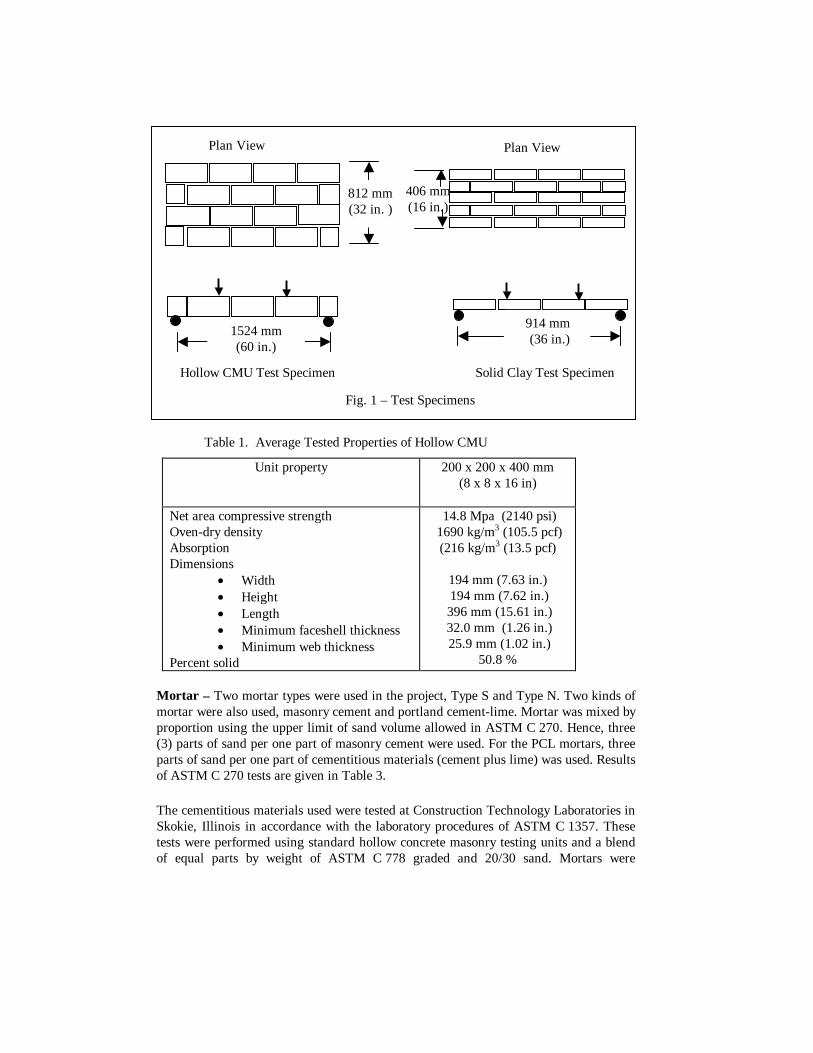
BACKGROUND The current (1999) Masonry Standards Joint Committee Building Code for Masonry Structures (ACI 530/ASCE5/TMS402)1 [MSJC Code] provides allowable flexural tensile stresses in Table 2.2.3.2. Many variables affect this allowable stress, two of which are whether portland cement/lime (PCL) or masonry cement (MC) mortar is used and whether or not the direction of stress is parallel or perpendicular to the bed joint. Comparison of allowable values for stresses parallel to the bed joint are double the corresponding values normal to the bed joint for ungrouted masonry. The hypothesis of the research was to show that masonry cement mortars experience a larger increase in flexural capacity than the 100% currently permitted. A difference was expected because the mechanism of failure is different for the two directions of stress. For stresses parallel to the bed joints, either a zig-zag pattern is expected, or alternating units are expected to fail in flexure. Either failure mode is less dependent of the bond between units and mortar than that determined for specimens tested perpendicular to bed joints. PREVIOUS RESEARCH Hamid and Drysdale2 tested wall panels in flexure parallel to the bed joint, and they concluded that the resulting failure mode is more complex than that which results from stress normal to the bed joints. In running-bond, ungrouted construction, the failure plane normally followed a zigzag path along both head and bed joints. For fully grouted construction, the researchers found that the failure mode was usually a straight line in which the crack followed through head joints and through the center of the masonry units. RESEARCH PLAN Applying flexural tensile stress parallel to the bed joint required a very different type of test specimen and apparatus than that required for producing stress normal to the bed joint. A much larger specimen was needed as illustrated in Fig. 1. The hollow concrete masonry specimen was basically the same as that used by Hamid and Drysdale2 in their research. Five replications each were tested with solid clay masonry units (solid brick) and hollow concrete masonry units (hollow CMU) constructed of masonry cement mortar and portland cement/lime mortar. With two unit types (hollow and solid), two kinds of mortar (masonry cement and portland cement/lime), two types of mortar (Type S and Type N) and five replications, a total of 2 x 2 x 2 x 5 = 40 specimens was required. Materials Masonry Units - Hollow concrete masonry units having nominal dimensions of 8 x 8 x 16 in. (203 x 203 x 406 mm) and a unit weight of approximately 100 pcf (1600 kg/m3) were selected. Solid clay masonry units complying with ASTM C 216 with a medium range initial rate of absorption (IRA) were chosen. Average tested values of CMUs and brick are reported in Table 1 and Table 2, respectively.
Table 1. Average Tested Properties of Hollow CMU
Unit property 200 x 200 x 400 mm (8 x 8 x 16 in)
Net area compressive strength Oven-dry density Absorption Dimensions
194 mm (7.63 in.) 194 mm (7.62 in.) 396 mm (15.61 in.) 32.0 mm (1.26 in.) 25.9 mm (1.02 in.)
50.8 %
Mortar – Two mortar types were used in the project, Type S and Type N. Two kinds of mortar were also used, masonry cement and portland cement-lime. Mortar was mixed by proportion using the upper limit of sand volume allowed in ASTM C 270. Hence, three (3) parts of sand per one part of masonry cement were used. For the PCL mortars, three parts of sand per one part of cementitious materials (cement plus lime) was used. Results of ASTM C 270 tests are given in Table 3. The cementitious materials used were tested at Construction Technology Laboratories in Skokie, Illinois in accordance with the laboratory procedures of ASTM C 1357. These tests were performed using standard hollow concrete masonry testing units and a blend of equal parts by weight of ASTM C 778 graded and 20/30 sand. Mortars were
Hollow CMU Test Specimen Solid Clay Test Specimen
Fig. 1 – Test Specimens
Plan View
1524 mm (60 in.)
812 mm (32 in. )
Plan View
914 mm (36 in.)
406 mm (16 in.)
proportioned by weight equivalents to the volume proportions previously indicated. Results of the ASTM C 1357 flexural bond strength tests are summarized in Table 4.
Table 2. Average Tested Properties of Solid Clay Brick
Unit property Value Compressive Strength, gross area Cold Water Absorption 5-Hour Boil Water Absorption Saturation Coefficient Initial Rate of Absorption Dimensions Width Height Length
81.04 MPa (11,754 psi) 4.61 % 6.67 %
0.69 13.0 g/min ⋅ 194 cm2
(13.0 g/min ⋅ 30 in.2)
88.9 mm (3.50 in.) 57.2 mm (2.25 in.) 194 mm (7.63 in.)
Table 3. ASTM C 270 Tests
Portland cement
Hydrated lime
Masonry cement
Sand Water Flow Air water retent
ion
Compressive strength, psi
(MPa)
Cement designat
ion gm gm gm gm gm % % % 7
days 28
days PCL-S 376 80 1440 311 107 5.7 76 20.8
(3020) 25.7
(3730) PCL-N 282 120 1440 329 109 5.3 83 10.2
(1480) 12.1
(1750)
MC-S 450 1440 260 114 17.9 78 14.1 (2050)
15.6 (2260)
MC-N 420 1440 250 106 19.2 82 5.4 (780)
6.6 (960)
Table 4. ASTM C 1357 Test Results
Mortar No. of
tests, Mean stress Standard
deviation Coefficient of Variation
n MPa (psi) Mpa (psi) % Type S - Masonry Cementr 30 0.63 (91.0) 0.07 (20.1) 22.1
Type N - Masonry Cement 30 0.40 (54.3) 0.07 (11.4) 21.0
Type S - Portland Cement/Lime 30 1.02 (163.8) 0.19 (25.7) 15.7
Type N - Portland Cement/Lime 30 0.77 (129.1) 0.12 (18.2) 14.1
Results of ASTM C 780 tests on mortar as used in the test specimens are reported in
Table 5. The compressive strength of 50.8 mm (2 in). cubes (C 780-A7.5) is reported. Air content was measured using the Volumetric method (C 780-A6.4) and cone penetration determined by ASTM C 780-A1. Lime - Hydrated lime complying with ASTM C 207 was used in the PCL mortar. Construction The wall specimens were constructed by experienced masons and cured in plastic bags. Mortar was mixed by volume in a mechanical mortar mixer. Faceshell bedding was used for hollow concrete masonry, and full bedding for solid clay masonry. Specimens were laid in running bond with the first course being placed directly on the concrete floor. The specimens were enclosed with large plastic bags on the day they were constructed and allowed to cure in the laboratory where the air was maintained at 72° ± 5° (22° ± 3°C) and a relative humidity of 50% ± 10%. Photos of the construction process are shown in Fig. 2.
Table 5. Properties of Mortar Used in Test Specimens
Peak load, kN (lbs.) Mortar Type 1 2 3
Average comp. stress,
Mpa (psi)
COV, %
Air, %
Cone penetration,
mm
PCL-S 24.40 (5486)
27.09 (6091)
25.65 (5767)
9.96 (1445)
5.24 2.5 60
PCL-N 10.36 (2830)
13.14 (2954)
13.15 (2956)
5.02 (728)
2.48 1.8 62
MC-S 16.15 (3630)
16.55 (3720)
15.58 (3503)
6.23 (904)
3.01 13 67
Hol
low
Con
cret
e M
ason
ry
MC-N 8.30 (1859)
8.59 (1930)
9.09 (2045)
3.35 (486)
4.83 14.25 67
PCL-S 28.47 (6400)
26.42 (5960)
26.24 (5900)
10.49 (1522)
4.49 2.5 60
PCL-N 16.46 (3700)
16.01 (3600)
6.24 (3650)
6.29 (913)
1.37 2.5 61
MC-S 21.62 (4860)
22.95 (5160)
21.64 (4865)
8.55 (1240)
3.46 14.5 67
Soli
d C
lay
Mas
onry
MC-N 10.50 (2360)
10.52 (2365)
10.45 (2350)
4.07 (590)
0.32 15.5 64
Fig. 2 - Hollow Concrete Masonry Walls Under Construction
Hollow concrete masonry and solid clay masonry specimens were constructed on different days so their testing age would be as close as practicable to the intended 28 days. After a 28-day curing period, specimens were tested as soon as practicable. In every case the specimens were tested at an age of either 28 or 29 days. Test Procedure The masonry panels were tested in a horizontal position. Extreme care was taken to avoid subjecting the specimens to flexural stresses during handling. To protect the specimens during handling, a “strong back” was devised. The specimens were tilted from their originally constructed vertical position to a horizontal position while being supported by a stiffened plywood pallet to uniformly support their weight. The flexural tensile stress resulting from self-weight in the horizontal position was included in the calculated stress at failure. Specimens were transported in the horizontal position on the pallet using the pallet jack (Fig. 3). In Fig. 4 (upper) the lower supports are shown before the specimen was rolled into place with a hand pallet jack. When the specimen was rolled into place, the two tines of the pallet jack that support the specimen straddled pivot A. Beam B was then set into Pivot A (Fig. 4 lower) and the pallet jack was slowly released causing the specimen to rest upon Beam B and Beam A. The upper spreader beams shown in Fig. 5 were then put into position. The upper and lower loading mechanism were both designed to accommodate any out-of-plane imperfections that may have existed in the test specimens by the use of swivels or pivots under one of the beams. Load was applied to the upper loading mechanism using a hydraulic jack (Fig. 4). When the specimen failed, the pallet jack was still underneath to catch the pieces.
The failed specimen was then pulled out of the test rig, observed and photographed and moved to a holding area.
Observations Failure Modes – All of the solid clay masonry specimens constructed using portland
cement/lime mortars failed as shown in Fig. 6. The fracture plane passed along a straight line through one line of head joints and brick in between the head joints. In contrast, the solid brick masonry specimens constructed of Type N masonry cement failed in a zigzag pattern as shown in Fig. 7. Solid masonry specimens constructed using
Type S masonry cement mortar failed in the same mode as the PCL specimens with only one exception.
Fig. 6 - Failure Along a Single Fracture Plane – Solid Brick Masonry Specimen
Fig. 7 - Failure Along a Zigzag Fracture Plane – Solid Brick Masonry Specimen
Failure modes for the hollow concrete masonry specimens were similar to those of the solid masonry specimens. All of the PCL specimens failed along a straight line through one line of head joints and the concrete masonry units in between the head joints. About half of the masonry cement specimens failed in this same manner. However, some of the masonry cement specimens failed as shown if Fig. 8. In this failure mode, the fracture line did not pass through the unit at one end of the specimen. Instead, the path went around the unit to both head joints. TEST RESULTS The results of the flexural tension tests for specimens made from hollow concrete masonry units and solid clay masonry units are given in Table 6. The mean values and other statistical information are also given for each group of five specimens. Also given in Table 6 are the allowable flexural tensile stresses in the MSJC Code. The ratio of measured strength to allowable strength is also tabulated in Table 6.
Table 6. Flexural Tension Test Results Parallel to Bed Joints
Fig. 8 - Failure Path Offset at Top Course – Hollow CMU Specimen
Figures 9 and 10 show the measured flexural stress plotted beside the allowable stress for each case tested. Figure 9 pertains to hollow concrete masonry and Fig. 10 to solid clay masonry.
Fig. 9 Measured vs. Allowable StressHollow Concrete Masonry
0
20
40
60
80
100
120
140
160
PCL-S PCL-N MC-S MC-NMortar Type
Str
ess
Measured stress
Code allowable
Fig. 10 - Measured vs. Allowable StressSolid Clay Masonry
0
100
200
300
400
500
PCL-S PCL-N MC-S MC-N
Mortar Type
Str
ess
Measured stressCode allowable
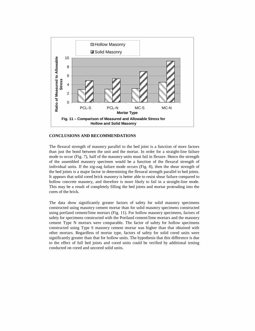
CONCLUSIONS AND RECOMMENDATIONS The flexural strength of masonry parallel to the bed joint is a function of more factors than just the bond between the unit and the mortar. In order for a straight-line failure mode to occur (Fig. 7), half of the masonry units must fail in flexure. Hence the strength of the assembled masonry specimen would be a function of the flexural strength of individual units. If the zig-zag failure mode occurs (Fig. 8), then the shear strength of the bed joints is a major factor in determining the flexural strength parallel to bed joints. It appears that solid cored brick masonry is better able to resist shear failure compared to hollow concrete masonry, and therefore is more likely to fail in a straight-line mode. This may be a result of completely filling the bed joints and mortar protruding into the cores of the brick. The data show significantly greater factors of safety for solid masonry specimens constructed using masonry cement mortar than for solid masonry specimens constructed using portland cement/lime mortars (Fig. 11). For hollow masonry specimens, factors of safety for specimens constructed with the Portland cement/lime mortars and the masonry cement Type N mortars were comparable. The factor of safety for hollow specimens constructed using Type S masonry cement mortar was higher than that obtained with other mortars. Regardless of mortar type, factors of safety for solid cored units were significantly greater than that for hollow units. The hypothesis that this difference is due to the effect of full bed joints and cored units could be verified by additional testing conducted on cored and uncored solid units.
Fig. 11 – Comparison of Measured and Allowable Stress for Hollow and Solid Masonry
0
2
4
6
8
10
PCL-S PCL-N MC-S MC-NMortar TypeR
atio
of
Mea
sure
d t
o A
llow
able
Str
ess
Hollow Masonry
Solid Masonry
ACKNOWLEDGEMENTS The research reported in this paper (PCA R&D Serial No. 2491a) was conducted by Clemson University and Construction Technology Laboratories, Inc., with the sponsorship of the Portland Cement Association (PCA Project Index No. 99-08). The contents of this paper reflect the views of the authors, who are responsible for the facts and accuracy of the data presented.
99/TMS 402-99, Building Code Requirements for Masonry Structures, American Concrete Institute, Detroit, American Society of Civil Engineers, New York, The Masonry society, Boulder, CO.
(2) Hamid 1988: Hamid, A. A., Drysdale, R. G., “Flexural Tensile Strength of
Concrete Block Masonry,” Journal of Structural Engineering, American Society of Civil Engineers, Vol. 114, No. 1, January, 1988, pp. 50-66
(3) ASTM 2000 Annual Book of ASTM Standards, Vol. 04.05, 100 Barr Harbor Drive,
West Conshohocken, Pennsylvania USA 19428-2959 ASTM C 216-97, Standard Specification for Facing Brick (Solid Masonry Units Made from Clay or Shale) ASTM C 90-97, Specification for Load-Bearing Concrete Masonry Units ASTM C 140-96b, Standard Methods of Sampling and Testing Concrete Masonry Units ASTM C 144-97, Standard Specification for Aggregate for Masonry Mortar ASTM C 270-97, Specification for Mortar for Unit Masonry ASTM C 143-90a, Test Methods for Slump of Hydraulic Cement Mortar ASTM C 1019-89a(93), Test Method for Sampling and Testing Grout ASTM C 1390-80 (reapproved 1993), Standard Test Methods for Flexural Bond Strength of Masonry
ASTM C 1357-96 Standard Test Methods for Evaluating Masonry Bond Strength
(4) Hedstrom 1991: Hedstrom, E. G, Tarhini, K. M., Thomas, R. D., Dubovoy, V. S.,
Klingner, R. E., Cook, R. A., “Flexural Bond Strength of Concrete Masonry Prisms Using Portland Cement and Hydrated Lime Mortars,” The Masonry Society Journal, The Masonry Society, Boulder, CO.
(5) Melander 1993: Melander, J. M., Ghosh, S. K., Dubovoy, V. S., Hedstrom, E. G.,
and Klingner, R. E., “ Flexural Bond Strength of Concrete Masonry Prisms Using Masonry Cement Mortars,” Masonry: Design and Construction, Problems and Repair, ASTM STP 1180, American Society for Testing and Materials, Philadelphia.