BY AKIRA AZUMA, SOICHI AZUMA, ISAO WATANABEAND TOYOHIKO FURUTA
Institute of Interdisciplinary Research, Faculty of Engineering, The University ofTokyo, Tokyo, Japan
Accepted 6 September 1984
SUMMARY
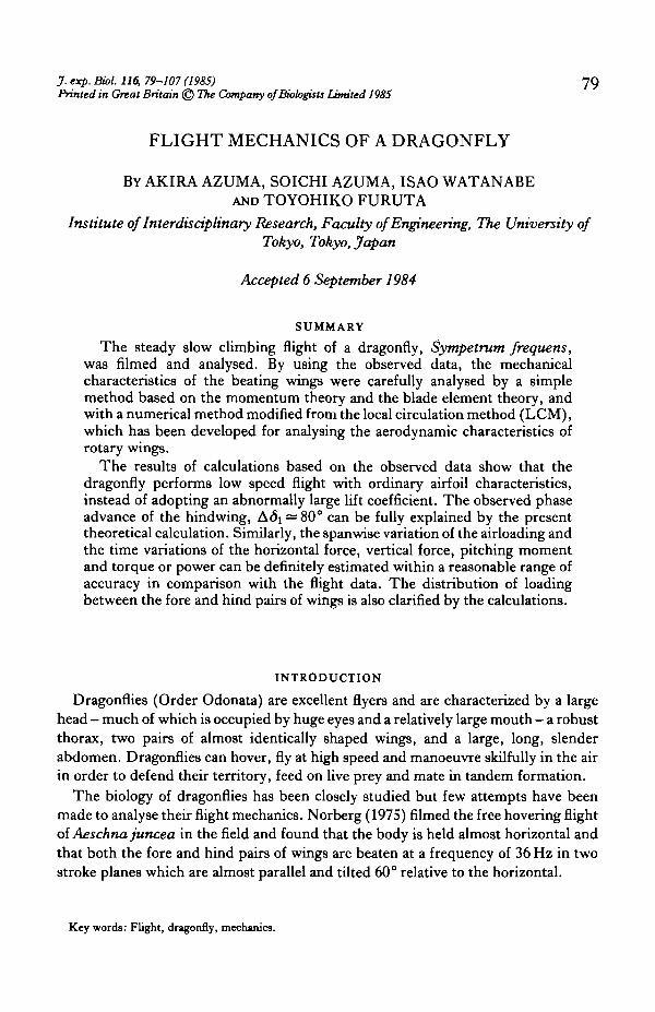
The steady slow climbing flight of a dragonfly, Sympetrum frequens,was filmed and analysed. By using the observed data, the mechanicalcharacteristics of the beating wings were carefully analysed by a simplemethod based on the momentum theory and the blade element theory, andwith a numerical method modified from the local circulation method (LCM),which has been developed for analysing the aerodynamic characteristics ofrotary wings.
The results of calculations based on the observed data show that thedragonfly performs low speed flight with ordinary airfoil characteristics,instead of adopting an abnormally large lift coefficient. The observed phaseadvance of the hindwing, Adi — 80° can be fully explained by the presenttheoretical calculation. Similarly, the spanwise variation of the airloading andthe time variations of the horizontal force, vertical force, pitching momentand torque or power can be definitely estimated within a reasonable range ofaccuracy in comparison with the flight data. The distribution of loadingbetween the fore and hind pairs of wings is also clarified by the calculations.
INTRODUCTION
Dragonflies (Order Odonata) are excellent flyers and are characterized by a largehead — much of which is occupied by huge eyes and a relatively large mouth — a robustthorax, two pairs of almost identically shaped wings, and a large, long, slenderabdomen. Dragonflies can hover, fly at high speed and manoeuvre skilfully in the airin order to defend their territory, feed on live prey and mate in tandem formation.
The biology of dragonflies has been closely studied but few attempts have beenmade to analyse their flight mechanics. Norberg (1975) filmed the free hovering flightoi Aeschna juncea in the field and found that the body is held almost horizontal andthat both the fore and hind pairs of wings are beaten at a frequency of 36 Hz in twostroke planes which are almost parallel and tilted 60° relative to the horizontal.
Key words: Flight, dragonfly, mechanics.
80 A. AZUMA AND OTHERS
Weis-Fogh (1972), in his analysis of hovering flight, assumed (1) a constantinduced velocity distribution over the stroke plane (based on the momentum theory),(2) a simple harmonic motion of the beating wings, and (3) a constant pitch along thespan of the wing. Then, following the techniques used in the analysis of helicopterrotor aerodynamics (Gessow & Myers, 1952), he carried out a steady aerodynamiccalculation on the beating wings by integrating the elemental forces acting on a bladeelement over the wings with the aid of strip analysis and by averaging these forces overone stroke cycle. The results required abnormally large lift coefficients, of 3-5 to 6-1.
In order to get a more realistic model of the flow field around the beating wings,Rayner (I979a,b,c) introduced the vortex theory for a pair of wings, in which a chainof coaxial, small-cored, circular vortex rings, simulating the trailing tip-vortices ofwings, was brought into the calculation of the induced velocity, as had been developedfor rotary wing aerodynamics (Heyson & Katzoff, 1957). However, unlike ahelicopter rotor in hovering flight, two pairs of wings arranged in tandem have time-varying airloadings and thus, as shown in Fig. 1, generate two corrugated wake sheetsfilled respectively with a sheet of shed vortices as well as trailing vortices. Thus, theinduced velocity, which, unlike that of the hovering rotor, is not always vertical, mustbe estimated from both the trailing and shed vortices. The wake of the vortices is ofconsiderable importance in and near hovering flight because the downwash generatedby a wing, which is retained and developed from the stroke plane, strongly affects theangle of attack of the wing in the subsequent stroke and of another wing operatingnearby.
In the case of a helicopter rotor, such effects of the downwash on the airloadings ofthe succeeding wing have been accurately analysed by simply introducing anattenuation coefficient instead of performing the complex integration over the vortexsheet (Azuma & Kawachi, 1979). This method of calculation, called the 'LocalMomentum Theory' (LMT), has been extended to the study of the unsteady aero-dynamics in the rotary wing of a helicopter (Azuma & Saito, 1982) and also, under thename of the 'Local Circulation Method' (LCM), to analyses of the highly skewed flowof propellers (Azuma, Nasu & Hayashi, 1981) and the windmill (Azuma, Hayashi &Ito, 1982).
Since the fundamental aerodynamic characteristics of the beating wing are muchlike those of the rotary wing, even though wing beating is a reciprocating motion andnot a rotational motion like that of a rotary wing, the LCM can similarly be applied tothe aerodynamic analysis of the beating wing with a slight modification of the method.
SYMBOLS
vector quantity defined by equation (36),lift coefficient,drag coefficient,interference coefficients between fore- and hindwings defined byequations (30),
Dragonfly flight
Ch, Cf attenuation coefficients denned by equation (31),c wing chord,D drag,F force,I moment of inertia of a wing about a flapping hinge,i, j running variables,k reduced frequency = (Oc/ZU,L lift,/ lift of wing element in vectorial form,A airloading = | /1,M pitching moment,m mass of wing,
81
Trailing vortices
Shed vortices
Wake sheet of left hindwing
Wake sheet of left forewing
Fig. 1. Wake model of beating wings. Wake sheets of left wings are shown.
82 A. AZUMA AND OTHERS
nPQRReV
r
(r, V, DsSe
sTtU
uVV
w(X, Y, Z)
(*. y . z )X
a
rA6edJI
P2
0yVa>
SubscriptaCGfh
i. j . n0
i
n-th harmonic; running variable,power,torque,radius of wing or half span of wing pair,Reynolds number,vectorial position of a vortex element,radial or spanwise position,polar coordinate system,area of stroke plane,swept area of stroke plane,spanwise unit vector,thrust,time,total velocity of wing element in vectorial form,total inflow velocity of wing element, U = | U |,forward velocity,induced velocity,weight,coordinate axes fixed in inertial space,local coordinate axes,non-dimensional spanwise position = r/R,angle of attack defined in equations (10),circulation,small increment; time step,phase difference of azimuth angle,phase difference of pitch angle,pitch angle,the circular constant,air density,summation,inflow angle defined in equations (10),tilt angle of stroke plane,flapping or azimuth angle,angular rate of flapping motion,
aerodynamic component,centre of gravity,fore,hind,i-th, j-th or n-th quantities,constant; o-th order quantities,inertial comDonent.
Dragonfly flight
P, p, n perpendicular components,T, q tangential components,X, Y, Z X, Y and Z components of (X, Y, Z) axes.
Superscript(~) mean value of ( ) defined by equation (16),( • ) , ( ' ' ) time derivatives = d( )/dt, d2( j/dt2 ,j time step.
83
MODES OF WING MOTION
A dragonfly, Sympetrumfrequens, flying under a spotlight in a darkened room wasfilmed with a high speed 16 mm movie camera (HIMAC) at 873 frames per second.The dimensions of the dragonfly are shown in Fig. 2 and Table 1.
In order to get a clear image of the feathering motion of the wings, a 2-5 mm widthof each wing tip was painted with 'Pentel White' 03-667-3331EX237 (Fig. 3). The
Root of forewing
' " J / J I
Root of hindwing
Xco
CG Z c G
Fig. 2. Diagram of dragonfly, Sympetrumfrequens. Arrangement of winga and centre of gravity, CG.
Table 1. Dimensions of the experimental dragonflyParameter
LengthMassWing span forewing
hindwingWing area forewing
hindwingAspect ratio forewing
hindwingTotal wing loadingTilt angle of the wing rootsDistance of wing rootsCentre of gravity, assumed
Dimensions
4-0 cm260 mg6-7 cm6-5 cm
4-42 cm2
5-44 cm2
4XlO"2m2-60xl0-4kg6-7xl0"2m6-5xl(T2m
4-42 x 10"* m2
5-44 X 10"4m2
10-27-8
0-0264gcm-2 2-58 Nm~ 2
8-2mmXcG = 7-2miI C G - 0
14°8-2xHT3m
n 7-2xlO-3m0
84 A. AZUMA AND OTHERS
mass of the paint was about 0-03 mg, which was about 2% of the mass of the wing(1-5 mg) and was somewhat less heavy than the pterostigma. The additional momentof inertia caused by the paint about the flapping hinge was 3-0 X 10~4gcm2, which wasabout 5% of that of the wing (5-6 X 10~3 gem2). The additional moment of inertia ofthe paint about the feathering axis was 2-2 X 10~6gcm2, which was about 3-5 % of thatof the wing (6-3 X 10~sgcm2). The local backward shift of the centre of mass at thepainted portion of the wing was about 4-6 % of the chord.
The mass of paint therefore has a small effect on the beating motion of the wing.However, an experimental check of the beating frequency by means of stroboscopeand video camera did not reveal any difference between a painted dragonfly and anaked or unpainted one, although the beating frequency was estimated to be reducedby about 2-5 %. In comparison with Norberg's result (1972) on the inertial effects ofthe pterostigma on the wing motion it can be considered that the mode of beating wasnot significantly altered by the painting and the analysed data gave useful informationabout the flight mechanics of the dragonfly.
Analysis of a series of frames of almost steady flight of the dragonfly in very slowclimbing flight revealed the following (Fig. 3).
(i) The body axis, which is a straight line connecting the tip of the head and the tipof the tail, is tipped about 10° head-up with respect to the horizontal.
(ii) The orbit of the wing tips of the hind pair is almost completely in a single planebut the profile of the orbit of the fore pair is a very thin ellipse, the major axis of whichmay be considered to be the stroke plane. Both stroke planes are tilted about 50° withrespect to the body axis, or y = 40° with respect to the horizontal as shown in Fig. 4.
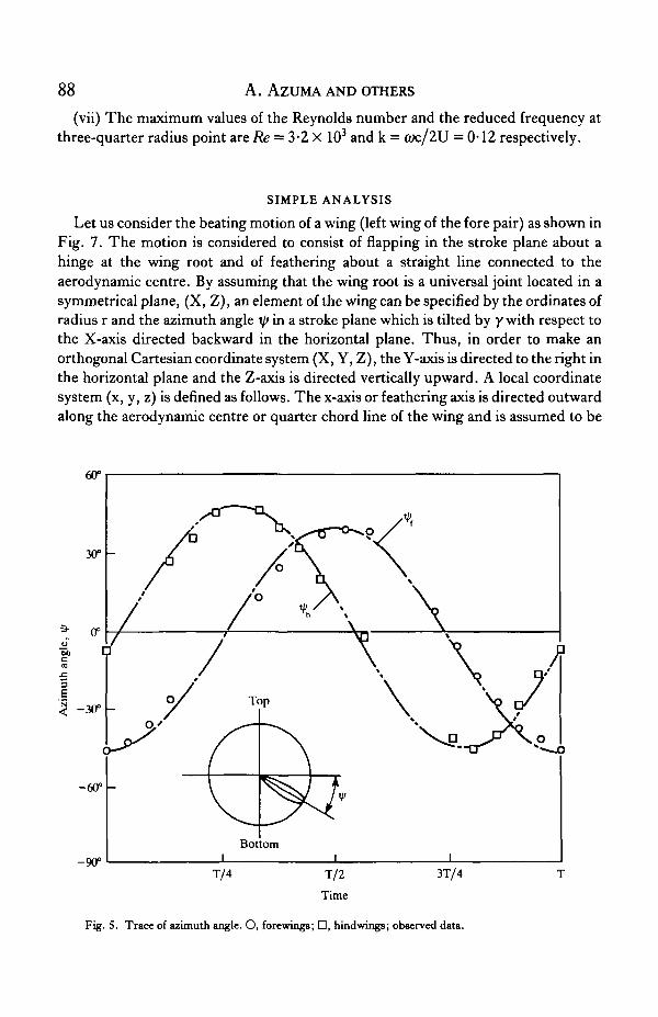
(iii) The beating frequency of all wings is 41*5 Hz.(iv) The flapping angles or the azimuth angles of the observed data in the respective
stroke planes are shown in Fig. 5. The Fourier expansion series of the observed data,
CD
V = V'o + Z t/»nco8(n<ut + <5n),n - 1
is well represented by:
t/>f=-3-43cos(<wt)(in degrees) (1)
By comparing this again with the observed data in Fig. 5, the angular speed was foundto be (0 — ZJIX 41-5 r a d s " ^ 15 000°s"1 and the phase difference between fore andhind pairs of wings to be AS = <5i>h — 6 l f = 77°, by which the fore pair followed thehind pair.
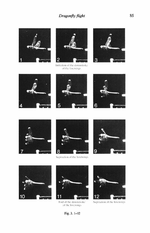
Fig. 3. A series of frames (time interval = 1-15 ms) showing modes of beating in steady flight of adragonfly (Sympetrum frequeni) (wing tips marked with white paint).
Dragonfly flight 85
Initiation of the downMrokeof tlic I'orewiims
Siipinalion of the hiiulwings
Hiul of the dowiistrokeof the forewines
Supinatioii of the forevsings
Fig. 3. 1-12
A. AZUMA AND OTHERS
I'roruition of the hiiulwings
Pronalion of the loicwings
Fig. 3. 13-24
Dragonfly flight 87(v) The flight velocity, V, is 0-54 ms"1, in a direction nearly normal to the stroke
plane.(vi) The pitch variation of the wings with respect to the stroke plane was deter-
mined by observing the wing tips, which were marked with white paint as statedbefore. The Fourier expansion series of the observed data,
and shown, with the observed data, in Fig. 6. It is interesting to find that the pitchchange consists of a higher (third) harmonic than the flapping stroke which consists ofthe first harmonic.
Flight velocity
= 0-5ms~'
Tip path planeof the forewing
Tip path planeof the hindwing
Horizontal
10°
Bod
Parallel to body axis
Fig. 4. OrbitB of wing tips.
88 A. AZUMA AND OTHERS
(vii) The maximum values of the Reynolds number and the reduced frequency atthree-quarter radius point are Re = 3*2 X 103 and k = OK/ZU = 0-12 respectively.
SIMPLE ANALYSIS
Let us consider the beating motion of a wing (left wing of the fore pair) as shown inFig. 7. The motion is considered to consist of flapping in the stroke plane about ahinge at the wing root and of feathering about a straight line connected to theaerodynamic centre. By assuming that the wing root is a universal joint located in asymmetrical plane, (X, Z), an element of the wing can be specified by the ordinates ofradius r and the azimuth angle ip in a stroke plane which is tilted by y with respect tothe X-axis directed backward in the horizontal plane. Thus, in order to make anorthogonal Cartesian coordinate system (X, Y, Z), the Y-axis is directed to the right inthe horizontal plane and the Z-axis is directed vertically upward. A local coordinatesystem (x, y, z) is defined as follows. The x-axis or feathering axis is directed outwardalong the aerodynamic centre or quarter chord line of the wing and is assumed to be
3
e
-60° -
T/4 T/2 3T/4
Time
Fig. 5. Trace of azimuth angle. O, forewings; D, hindwings; observed data.
Dragonfly flight 89
210°
Fig. 6. Pitch variation. O, forewings; D, hindwings; observed data.
common for all wing sections. The y-axis is directed in the direction of the inflow atthe wing section in consideration. The z-axis is directed to make an orthogonalCartesian coordinate system together with the other two axes. Then thetransformation matrix between the (X, Y, Z) axes and the (x, y, z) axes can be givenby:
X
Y
Z
X
—sinT/>cosy
—cosV
—sini/>siny
y
cosxp cos0 cosy+sin0 siny
—sint/;cos0
cosrp coscp siny — sin0 cosy
z
cost/> sin0 cosy — cos<p siny
—sini/;sin0
cost/; sin0 siny+cos(p cosy
(3)
In the calculation of the aerodynamic forces, the following assumptions areintroduced:
(i) The respective wings sustain a quarter of the total force evenly, T/2, where T isthe mean thrust or the mean force generated by the respective pairs of wings and is,because of the negligibly small parasite drag of the body, balanced by the weight:
T = W/2cosy. (4)
(ii) The pitch angle is independent of the spanwise position x — r/R where R is halfof the wing span.
90 A. AZUMA AND OTHERS
(iii) The induced velocities generated by the fore- and hindwings are constant overand normal to the stroke planes and are determined by the momentum theory as:
vf = -(V/2) + VT/2pSe + (V/2)2 for forewing
vh = - (V + ChfVf) + VT/2pSe + (V + Chfvf)2/4, for hindwing
(5)
where Se is the area swept by one pair of beating wings and CJJ is an interferencecoefficient specifying the effect of the induced velocity of the fore pair on the hindpair, whereas the effect of the hind pair on the fore pair has been neglected because it isso small.
(iv) By neglecting the outflow along the span, the aerodynamic forces acting on ablade element are given by those of two-dimensional airfoils and can be integratedalong the span without any interference among the elements.
(v) The aerodynamic characteristics of the wing section or airfoil at low Reynoldsnumber (Fig. 8) were modelled by referring to those given by Vogel (1967) and Jensen(1956), and modified to have the maximum lift coefficient of C^>max—l-8 by
Advancingdirection
Horizontal
Fig. 7. Coordinate systems related to the beating motion of a wing.
Dragonfly flight 91
ucuS
in
A
-40
2-0
1-5
1-0
0-5
-20 /
-1-5
-
-
0
;
/
/
i
20i
40
\
Angle of attack, a (degrees)
B 20
\ 15
\ 10
\ 05
i i
-40 -20
-0-5
- 1 0
-1-5
- /
_ /
i i
0 20 40
-
-
-
Angle of attack, a (degrees)
Fig. 8. Assumed aerodynamic characteristics of an airfoil: (A) lift, (B) drag.
considering the effects of the unsteady separated flow and of the dynamic stall on themaximum lift, as presented, for example, by Izumi & Kuwahara (1983), Conner,Willey & Twomey (1965) and Ericsson & Reding (1971).
Referring to Fig. 9A,B, which shows the geometrical relationships about the wingstroke plane, the relative velocities and the aerodynamic forces of the wing for down-and up-strokes respectively, the tangential and perpendicular velocity components,U T and Up, are given by:
where
V = Vo +
%l>- -T/>i<osin(<yt
Then, the elemental lift and drag can be given by
(6)
(7)
(8)
92 A . AZUMA AND OTHERS
Lift (dL)
Flight direction
Pitch angle with respectto the stroke plane
Induced velocity
Forward velocity
B
Flight direction
Lift ( -dL)
Forward velocity
Induced velocity
Angle of attack UP = V+v
Pitch angle with respectto the stroke plane
Chord line
Fig. 9. Relative velocities and aerodynamic forces acting on a blade element. (A) Downstroke; (B)upstroke.
Dragonfly flight 93where the relative speed U, the angle of attack a, and the inflow angle <p arerespectively given by:
U = V U T2 + UP
Z =
= tan-1(UP/UT).
2 + (V (9)
(10)
Since the lift and drag of the wing element are directed to the z- and y-axesrespectively, the total forces of one pair of wings along the X- and Z-axes and torque,Q, about the joint (positive for flapping up) can respectively be given by:
Similarly, the thrust, T, pitching moment (head-up positive), M, and the requiredaerodynamic power, P, are respectively given by:
T = Fzcosy — Fxsiny = 2 (dLcos<£ - dDsin<p)
= p V2c{CAcos0 - Cd8in0}drJ o
(13)
M =
f R— p\ U
Jo
P = QV* = 2 (
- FxzCG
'd(cos > cos0 siny — sin0 cosy)
(cos r/> sin0 siny + cos0 cosy)}
sin^siny)
— cos0siny)}]dr
(p + dDcos(p)rip
(14)
= p 6i)}rdr,(15)
where the aerodynamic power for feathering motion, being very small, is neglected.
94 A. AZUMA AND OTHERS
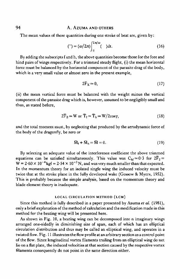
The mean values of these quantities during one stroke of beat are, given by:
O = (fl>/2*) ( )dt. (16)Jo
By adding the subscripts f and h, the above quantities become those for the fore andhind pairs of wings respectively. For a trimmed steady flight, (i) the mean horizontalforce must be balanced by the horizontal component of the parasite drag of the body,which is a very small value or almost zero in the present example,
2Fx = 0, (17)
(ii) the mean vertical force must be balanced with the weight minus the verticalcomponent of the parasite drag which is, however, assumed to be negligibly small andthus, as stated before,
2Fz = WorT f = Th = W/2cosy, (18)
and the total moment must, by neglecting that produced by the aerodynamic force ofthe body of the dragonfly, be zero or
Mf + Mh = M = 0. (19)
By selecting an adequate value of the interference coefficient the above trimmedequations can be satisfied simultaneously. This value was ^ = 0*3 for 2F2 =W = 2-60 X 10~4 kgf = 2-54 X 10~3 N, and was very much smaller than that expected.In the momentum theory for an isolated single wing the induced velocity must betwice that at the stroke plane in the fully developed wake (Gessow & Myers, 1952).This is probably because the simple analysis, based on the momentum theory andblade element theory is inadequate.
LOCAL CIRCULATION METHOD (LCM)
Since this method is fully described in a paper presented by Azuma et al. (1981),only a brief explanation of the method of calculation and the modification made in thismethod for the beating wing will be presented here.
As shown in Fig. 10, a beating wing can be decomposed into n imaginary wingsarranged one-sidedly in diminishing size of span, each of which has an ellipticalcirculation distribution and thus may be called an elliptical wing, and operates in atwisted flow. Fig. 11 illustrates the flow profile at an arbitrary section as a control pointof the flow. Since longitudinal vortex filaments trailing from an elliptical wing do notlie on a flat plate, the induced velocities at that section caused by the respective vortexfilaments consequently do not point in the same direction either.
Dragonfly fligh t 95
Elliptical circulation distribution { .oAirloading
Induced velocitydistribution
Fig. 10. Decomposition of a beating wing into n wings each having an elliptical distribution ofcirculation.
V+v,
Fig. 11. Relative velocities and forces acting on a blade element at a control point.
96 A. AZUMA AND OTHERS
By adopting the Kutta-Jukowsky theorem and the blade element theory, theairloading, /, the circulation, F, and the lift coefficient as a function of angle of attack
can be related as follows:
/ = pTU X s (20)
(21)
(22)
where S is a spanwise unit vector. The angle of attack or is, here, considered to be givenby:
a=e-4>(23)
0 = tan"1(UP/UT),
where U T and Up are respectively tangential and perpendicular components of thetotal inflow velocity U, with respect to a stroke plane, at a control point underconsideration.
Referring to Fig. 11, the perpendicular and tangential components of the inducedvelocity with respect to the total inflow U can be given by the summation of thecomponents induced by the respective wings,
(24)
and are related to the circulation AF; as follows:
Rcos{0(r')-0(ri)}dAFi(r')
,
(25)
Dragonfly flight 97
Then, the tangential and normal components of the induced velocity and of the totalinflow velocity with respect to the stroke plane can be given by:
vt = —
U T =
vqsin0(26)
(27)
where vn 0 is the normal component of the induced velocity with respect to the strokeplane, generated and left by the preceding wings at the control point, whereas vn isthat generated by the present wing at the present time.
If the induced velocity left on the control point, Vno, is specified as a known valueor related to other known variables, then by combining equations (20) to (27), thespanwise distribution of the airloading, circulation and the perpendicular and tan-gential components of the induced velocity can be solved numerically. If the inducedvelocity outside the elliptical wings is neglected, then the solution can be obtainedsuccessively (Azuma & Kawachi, 1979).
Now let us consider the induced velocity vno- In the local circulation method for arotary wing (Azuma et al. 1981) the induced velocity left at the control point at timestep tj_i is considered to be given by multiplying the induced velocity generated at thecontrol point at a time tj_i, v'"1, by an attenuation coefficient O~l as C'"1^"1. In thecase of two pairs of wings, the induced velocities left at the control points (Pf and Ph)for the fore and hind pairs of wings, can respectively be given by:
(vn,o)!f = CJ ' ( v j 1 + CfhvJh
1)(28)
where Vf and v h are respectively the induced velocities of the fore and hind pairs ofwings at the control points at the time tj_i, and where Cf , Cj, and Cn,, Chf aredirect or time-related attenuation coefficients and cross- or space-related interferencecoefficients respectively.
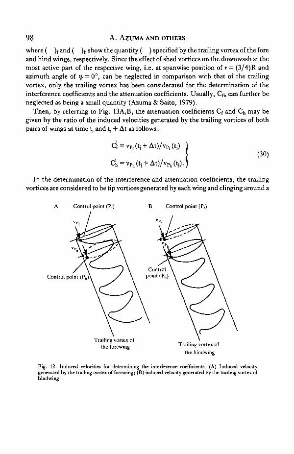
By referring to Fig. 12A, B, the interference coefficients Cn, and Chf may be given bythe ratio of the induced velocity generated by the respective system of trailing vortexas follows:
(29)
98 A. AZUMA AND OTHERS
where ( )f and ( )h show the quantity ( ) specified by the trailing vortex of the foreand hind wings, respectively. Since the effect of shed vortices on the downwash at themost active part of the respective wing, i.e. at spanwise position of r = (3/4)R andazimuth angle of ip = 0°, can be neglected in comparison with that of the trailingvortex, only the trailing vortex has been considerated for the determination of theinterference coefficients and the attenuation coefficients. Usually, Cfh can further beneglected as being a small quantity (Azuma & Saito, 1979).
Then, by referring to Fig. 13A,B, the attenuation coefficients Cf and Cj, may begiven by the ratio of the induced velocities generated by the trailing vortices of bothpairs of wings at time t, and tj + At as follows:
(30)
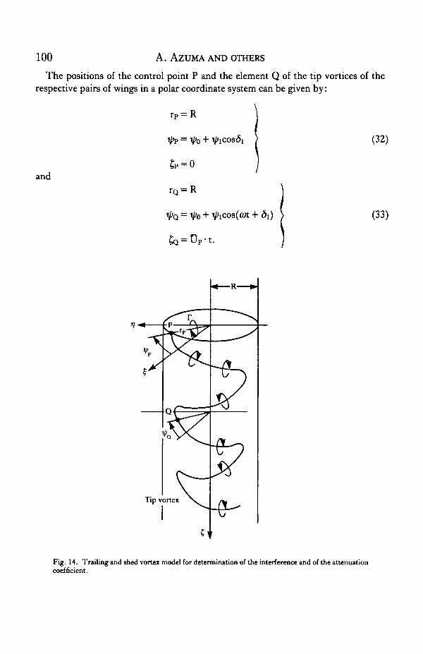
In the determination of the interference and attenuation coefficients, the trailingvortices are considered to be tip vortices generated by each wing and clinging around a
Control point (Pf) B Control point (Pr)
Control point (Ph)
Trailing vortex ofthe forewing Trailing vortex of
the hindwing
Fig. 12. Induced velocities for determining the interference coefficients. (A) Induced velocitygenerated by the trailing cortex of forewing; (B) induced velocity generated by the trailing vortex ofhindwing.
Dragonfly flight 99wake cylinder as shown in Fig. 14. The respective vortex systems are assumed to flowdownstream with a constant flow speed Up which is the mean value of the normal flowUp or:
1 r(31)
where S is the area of the respective stroke plane.
A Control point (Pf) Control point (Pf)
Forewing
• Hindwing
( i ) t - t
Fig. 13. Induced velocities for determining the attenuation coefficients. (A) Forewing; (B)hindwing.
100 A. AZUMA AND OTHERS
The positions of the control point P and the element Q of the tip vortices of therespective pairs of wings in a polar coordinate system can be given by:
and
rP = R
(32)
rQ = R
VQ = V'o + V>icos(<yt + (33)
Fig. 14. Trailing and ahed vortex model for determination of the interference and of the attenuationcoefficient.
Dragonfly flight 101
120°
90°
60°
* 30°
I 0°u•a
< -30°
-60°
-90°
-120°
- Downstroke - Upstroke of hindwing *-Downstroke —
Forewing
Hindwing
\
T/4 \r/2 Time
Linear range of thelift coefficient
• Downstroke of forewing • • Upstroke of forewing -
20
-Downstroke *• -Upstroke of hindwing - •-Downstroke—
-Upstroke of forewing-
T/4 T/2 3T/4
Time
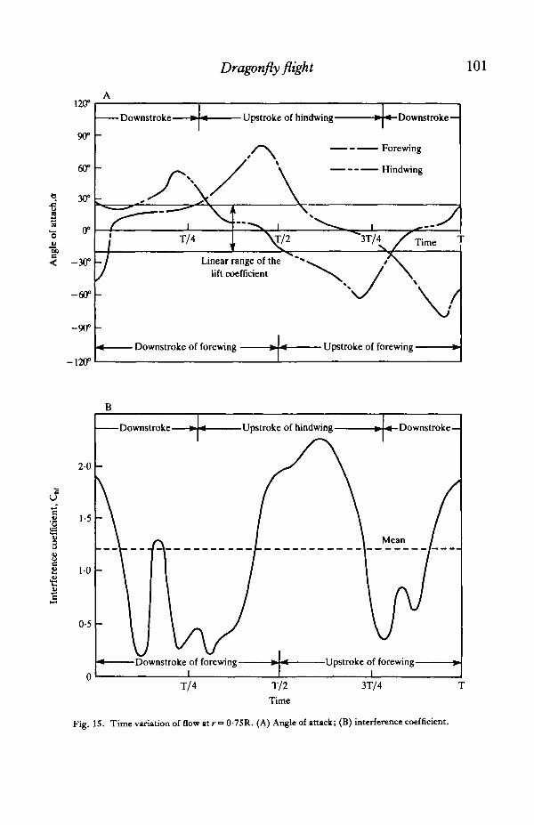
Fig. IS. Time variation of flow at r = 0-75R. (A) Angle of attack; (B) interference coefficient.
- -
Downstroke Upstroke of hindwing Downstroke 6.0 600
c----Downstroke of forewing Upstroke of forewing-
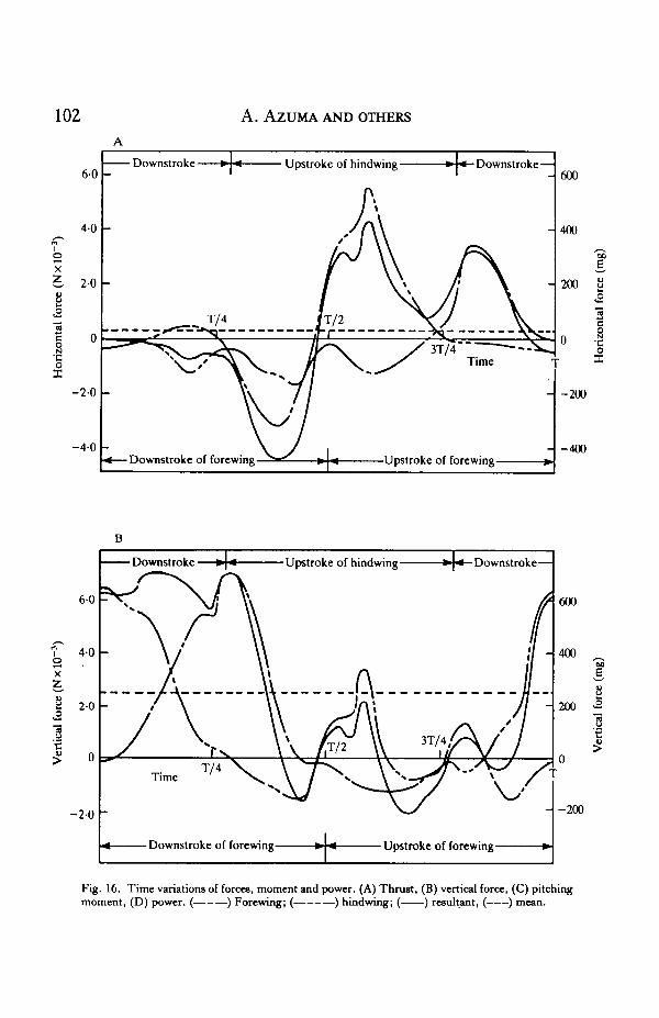
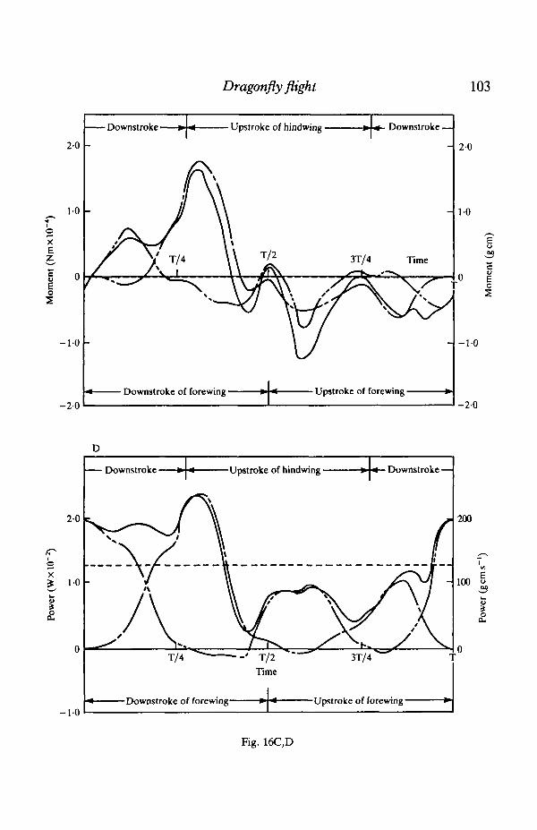
Fig. 16. Time variations of forces, moment and power. (A) 'bust, (B) vertical force, (C) pitching moment, (D) power. (---) Forewing; (----) h h h i n g ; (-1 resultant, (---I mean.
Dragonfly fligh t 103
Downstroke »
20
10
xE
I
-1-0
Upstroke of hindwing » « Downstroke —
2 0
• Downstroke of forewing Upstroke of forewing •- 2 0
cuo
-1-0
-2-0
D
Downstroke Upstroke of hindwing frU Downstroke —
Fig. 16C,D
104 A. AZUMA AND OTHERS
Then, by applying Biot-Savart's law, the induced velocity at the control point, P, isdetermined by:
» I a I (34)where
a = rP - rQ (35)
and the circulation F(t) is assumed to be represented at the three-quarter radius point,r = 0-75R.
r(t)=^{cUQ(tf)}r=0.75R. (36)
By introducing iterative calculation, these equations can be used to determine theinduced velocity distribution vno at time tj for both the fore and hind pairs of wingssuccessively.
Since the aerodynamic forces along z- and y-axis components can again be given by:
(37)
the total forces and moments generated by the respective pair of wings can be obtainedfrom equations (11) to (16).
RESULTS CALCULATED BY THE LCM
By applying the LCM for a steady, slow-climbing flight of a dragonfly and by usingthe observed data, the following results have been obtained.
The time variations of the angle of attack a, and the interference coefficient Chf atthe three-quarter radius point of the wing for the fore and hind pairs are shown in Fig.15. It is remarkable that the angles of attack remain in the linear range of the liftcoefficient during the effective phase of the respective strokes and the interferencecoefficient varies appreciably. The Cw is less effective near the switching of thebeating strokes of the hindwings, from up to down and down to up, where the inducedvelocity generated by the forewing is predominant. This results from adequateselection of the phase lead of the hindwing 8\ = 77°. The mean value of the inter-ference coefficient is about Chf = 1 "2, which is more reasonable and much larger thanthat given in the Simple Analysis section (p. 88).
Fig. 16 shows the time variations of the horizontal force, vertical force, pitchingmoment and power. The negative horizontal force is generated mainly by theforewing in the latter half of its downstroke, whereas the positive horizontal force isgenerated by the hindwing in the last half of its upstroke. The mean horizontal force isa very small positive value because the dragonfly is climbing only slowly.
Dragonfly fligh t 105
3-0
I 2-0
- 1 0
Mean power Mean thrust Mean pitching moment
xflPhase difference,
Fig. 17. Effect of the phase differences of the mean vertical force (2F, X 103, N), mean horizontalforce (2F, X 103, N), mean pitching moment (M X 107, Nm) and mean power (P X 102, W).
11oX
eo
>rqu
60
4-0
2-0
nU
-2-0
- 4 0
-
-
/
-
/
/
\
T/4\
\
Downstroke
s\\\\ Q .
\
\
T/2Time
Q. /
X-»^/3T/4>/ N
s
\
_
-
11
11
1t
-
- 0-6
- 0-4
0-2 j iO3
0 £•
-0-2
0-4
Fig. 18. Time variation of the torque of a forewing. Qlf inertia torque; Q., aerodynamic torque.
106 A. AZUMA AND OTHERS
The vertical force is mostly generated in the downstroke of the respective wings.The total mean vertical force is equal to the weight of the dragonfly. The higherharmonics of pitch changes are important to keep this balance.
The moment about the centre of gravity, which was not always accurately observedbut only roughly measured, varies appreciably during the wing cycle, from positive inthe downstroke of the forewing to negative in the upstroke of the forewing. The meanvalue is, however, almost zero for a steady flight.
The power is always positive and its variation is very similar to that of the verticalforce. That is to say, the power is mainly consumed to sustain the weight of the body inthis example. The mean value of this required power is equivalent to a 'specific power'of 160 W kg" i, which is the required power per unit mass of muscle. This value falls ina reasonable range (70-260 Wkg"1) as estimated by Weis-Fogh (1975, 1977).
The effects of the phase difference Adi of the beating motion between the fore andhind pairs of wings on the mean values of horizontal force, vertical force, pitchingmoment and power are shown in Fig. 17. The horizontal force and pitching momentare strongly dependent on the phase difference or phase lead of the hindwing d\,whereas the vertical force and power are almost invariant or slightly dependent onthe phase difference. There are two phase differences for zero pitching moment,Adi = 80° and 150°. As shown by dotted lines in Fig. 17, by adjusting the CG positionfrom —10% (forward) to +10% (backward) of the mean wing chord the abovetrimmed phase difference varies as 60°<A6i<95° and 140°< A<5j < 190°. Theformer phase difference gives a small mean horizontal force for low-speed flightwhereas the latter one generates a large mean horizontal force probably for high-speedflight. The observed value of A<5i = 80° clearly corresponds to the above low-speedflight. Contrary to expectation, the power was not small at the former trimmed point.
In the above calculations, the unsteady flow effects on the aerodynamic forces andmoments acting on the beating wings have not been introduced. In the linear unsteadywing theory the effects of periodically shed vortices are introduced by simplymultiplying either the Theodorsen function for the wing motion or the Sear's functionfor the change of oncoming flow by the lift slope as precisely explained in textbooks(e.g. Bisplinghoff, Ashley & Halfman, 1955). In the present calculation, however, theeffects of shed vortices have been introduced as the spanwise variation of the inducedvelocity generated and left by the preceding blades by the term of (vno)} or h as givenby equation (31). Since the chordwise gradient of this term is nearly equivalent to theshed vortices (Azuma et al. 1982), other unsteady effects have been omitted.
CONTRIBUTION OF INERTIAL FORCE
The inertial force accompanying the beating motion results mainly from theflapping motion in the stroke plane. The inertial torque of a single wing assumed to berigid can be given by:
[ ^ I i j l / , (38)
Dragonfly flight 107
where I is the inertial moment about the flapping hinge. By assuming the wing to be athin rectangular plate, this inertial moment is estimated as I = 5-5 X 10~n kgs~2.
Shown in Fig. 18 are the time variations in the inertial torque Q; and theaerodynamic torque Qa of a forewing beating in the same steady flight. In the latterhalf of both the down- and upstrokes the inertial torque assists to compensate theaerodynamic torque. It is, however, known that the inertial torque can be cancelled orreduced by adopting either an elastic property into the wing itself or a resilientmaterial such as an apodeme at the flapping hinge of the wing (Weis-Fogh, 1972;Alexander, 1975).
R E F E R E N C E S
ALEXANDER, R. M. (1975). Biomechanics. London: Chapman & Hall Ltd. New York: Halated Press.AZUMA, A., HAYASHI, T . & ITO, A. (1982). Application of the local circulation method to the flutter analysis of
rotary wings. Eighth European Rotorcraft and Powered Lift Aircraft Forum.AZUMA, A. & KAWACHI, K. (1979). Local momentum theory and its application to the rotary wing. J. Aircraft 16,
6-14.AZUMA, A., NASU, K. & HAYASHI, T. (1981). An extension of the local momentum theory to the rotors operating
in twisted flow field. Vertica 7, 45-59.AZUMA, A. & SATTO, S. (1979). Application of the local momentum theory to the aerodynamic characteristics of
multi-rotor systems. Vertica 3, 131-144.AZUMA, A. & SAITO, S. (1982). Study of rotor gust response by means of the local momentum theory. J. Am.
Helicopter Soc. 27, 58-72.BISPLINGHOFF, R. L., ASHLEY, H. & HALFMAN, R. L. (1955). Aeroelasticity. Reading, MA: Addison-Wesley
Publishing Co. Inc.CONNER, F., WILLEY, C. &TWOMEY, W. (1965). A flight and wind tunnel investigation of the effect of angle-of-
attack rate on maximum lift coefficient. NASA CR-321.ERICSSON, L. E. & REDING, J. P. (1971). Unsteady airfoil stall, review and extension. J. Aircraft 8, 609-616.GESSOW, A. & MYERS, G. C , JR. (1952). Aerodynamics of the Helicopter. New York: Macmillan Publishing
Company.HEYSON, H. H. & KATZOFF, S. (1957). Induced velocities near a lifting rotor with nonuniform disc loading.
NACA Rep. 1319.ISHIDA, S. (1980). Insects'Life in Japan, Vol. 2, Dragonflies. Tokyo: Hoikusha Publishing Co. Ltd.IZUMI, K. & KUWAHARA, K. (1983). Unsteady flow field, lift and drag measurements of impulsively started
elliptic cylinder and circular-arc airfoil. AIAA 16th Fluid and Plasma Dynamics Conference, Danvers, MAU.S.A., July 12-14.
JENSEN, M. (1956). Biology and physics of locust flight. III . The aerodynamics of locust flight. Phil. Trans. R.Soc. Ser.B 239, 511-552.
NORBERG, R. AKE. (1972). The pterostigma of insect wings: an inertial regulator of wing pitch. J. comp. Physiol.81, 9-22.
NORBERG, R. AKE. (1975). Hovering flight of the dragonflyAeschmajuncea L.: kinematics and aerodynamics.In Swimming and Flying in Nature, Vol. 2, (eds T. Y.-T. Wu, C. J. Brokaw & C. Brennen), pp. 763-781.New York: Plenum Press.
RAYNER, J. M. V. (1979a). A vortex theory of animal flight. I. The vortex wake of a hovering animal. J . FluidMech. 91, 697-730.
RAYNER, J. M. V. (19796). A vortex theory of animal flight. II . The forward flight of birds. J. Fluid Mech. 91,731-763.
RAYNER, J. M. V. (1979c). A new approach to animal flight mechanics. J. exp. Biol. 80, 17-54.VOGEL, S. (1967). Flight in Drosophiia. I I I . Aerodynamic characteristics of fly wings and wing models. J. exp.
Biol. 46, 413-443.WEIS-FOGH, T. (1972). Energetics of hovering flight in hummingbirds and in Drosophiia. J. exp. Biol. 56,
79-104.WEIS-FOGH, T. (1975). Flapping flight and power in birds and insects, conventional and novel mechanisms. In
Swimming and Flyingin Nature, Vol. 2, (eds T. Y.-T. Wu, C. J. Brokaw & C. Brennen), pp. 729-762. NewYork: Plenum Press.
WEIS-FOGH, T. (1977). Dimensional analysis of hovering flight. In Scale Effects in Animal Locomotion.London: Academic Press.