CSM_61F-GP-N@_DS_E_7_2 1 Floatless Level Switch (Compact, Plug-in Type) 61F-GP-N@ Space-saving Design Ideal for Control Panel Downsizing. Easy Maintenance. • Compact: 49.4 × 38 × 84 mm (H×W×D). • Easy identification of operating status with LED operation indicator. • Independent DPDT contacts on 11-Pin Models. • CE marking and UL/CSA compliance. ■ Model Number Legend ■ Ordering Information Note: When ordering, specify the desired operating voltage at the end of the model number. 1. No. of Pins 2. Type N: 11 pins N8: 8 pins Blank: General-purpose L 2KM: Long-distance (for 2 km) L 4KM: Long-distance (for 4 km) H: High-sensitivity D: Low-sensitivity R: Two-wire T: High-temperature Refer to Safety Precautions for Floatless Level Controllers. Position of LED indicator 2 1 61F-GP-@@ Type General-purpose Long-distance (for 2 km) Long-distance (for 4 km) Model Model Model 11-pin 61F-GP-N 61F-GP-NL 2KM 61F-GP-NL 4KM Type High-sensitivity Low-sensitivity Two-wire Model Model Model 11-pin 61F-GP-NH 61F-GP-ND 61F-GP-NR Type Tropical environments High-temperature Model Model 8-pin 61F-GP-N-TDL 61F-GP-NT Type General-purpose Long-distance (for 2 km) Long-distance (for 4 km) Model Model Model 8-pin 61F-GP-N8 61F-GP-N8L 2KM 61F-GP-N8L 4KM Type High-sensitivity Low-sensitivity Two-wire Model Model Model 8-pin 61F-GP-N8H 61F-GP-N8D 61F-GP-N8R 61F-GP-N8HY Example: 61F-GP-N [220 VAC] Desired supply voltage
Transcript
CSM_61F-GP-N@_DS_E_7_2
1
Floatless Level Switch (Compact, Plug-in Type)
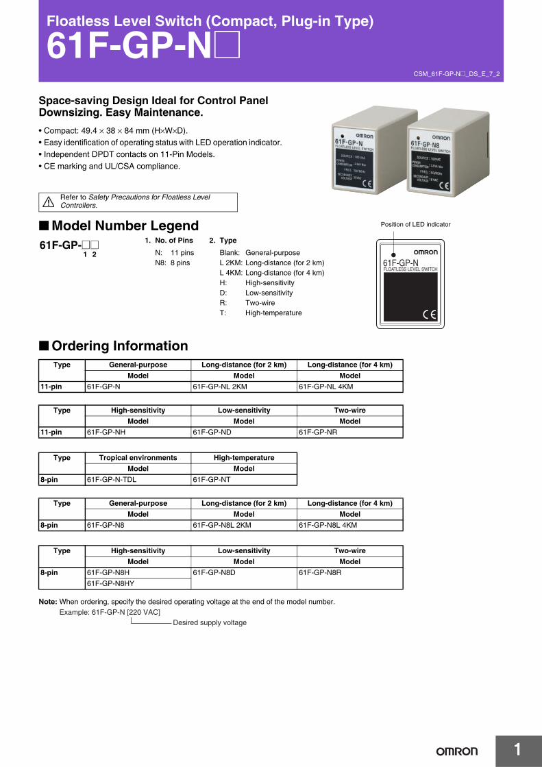
61F-GP-N@Space-saving Design Ideal for Control Panel Downsizing. Easy Maintenance.• Compact: 49.4 × 38 × 84 mm (H×W×D).• Easy identification of operating status with LED operation indicator.• Independent DPDT contacts on 11-Pin Models.• CE marking and UL/CSA compliance.
■ Model Number Legend
■ Ordering Information
Note: When ordering, specify the desired operating voltage at the end of the model number.
Refer to Safety Precautions for Floatless Level Controllers.
Position of LED indicator
2161F-GP-@@
Type General-purpose Long-distance (for 2 km) Long-distance (for 4 km)Model Model Model
11-pin 61F-GP-N 61F-GP-NL 2KM 61F-GP-NL 4KM
Type High-sensitivity Low-sensitivity Two-wireModel Model Model
11-pin 61F-GP-NH 61F-GP-ND 61F-GP-NR
Type Tropical environments High-temperatureModel Model
8-pin 61F-GP-N-TDL 61F-GP-NT
Type General-purpose Long-distance (for 2 km) Long-distance (for 4 km)Model Model Model
8-pin 61F-GP-N8 61F-GP-N8L 2KM 61F-GP-N8L 4KM
Type High-sensitivity Low-sensitivity Two-wireModel Model Model
8-pin 61F-GP-N8H 61F-GP-N8D 61F-GP-N8R61F-GP-N8HY
Example: 61F-GP-N [220 VAC]Desired supply voltage
61F-GP-N@
2
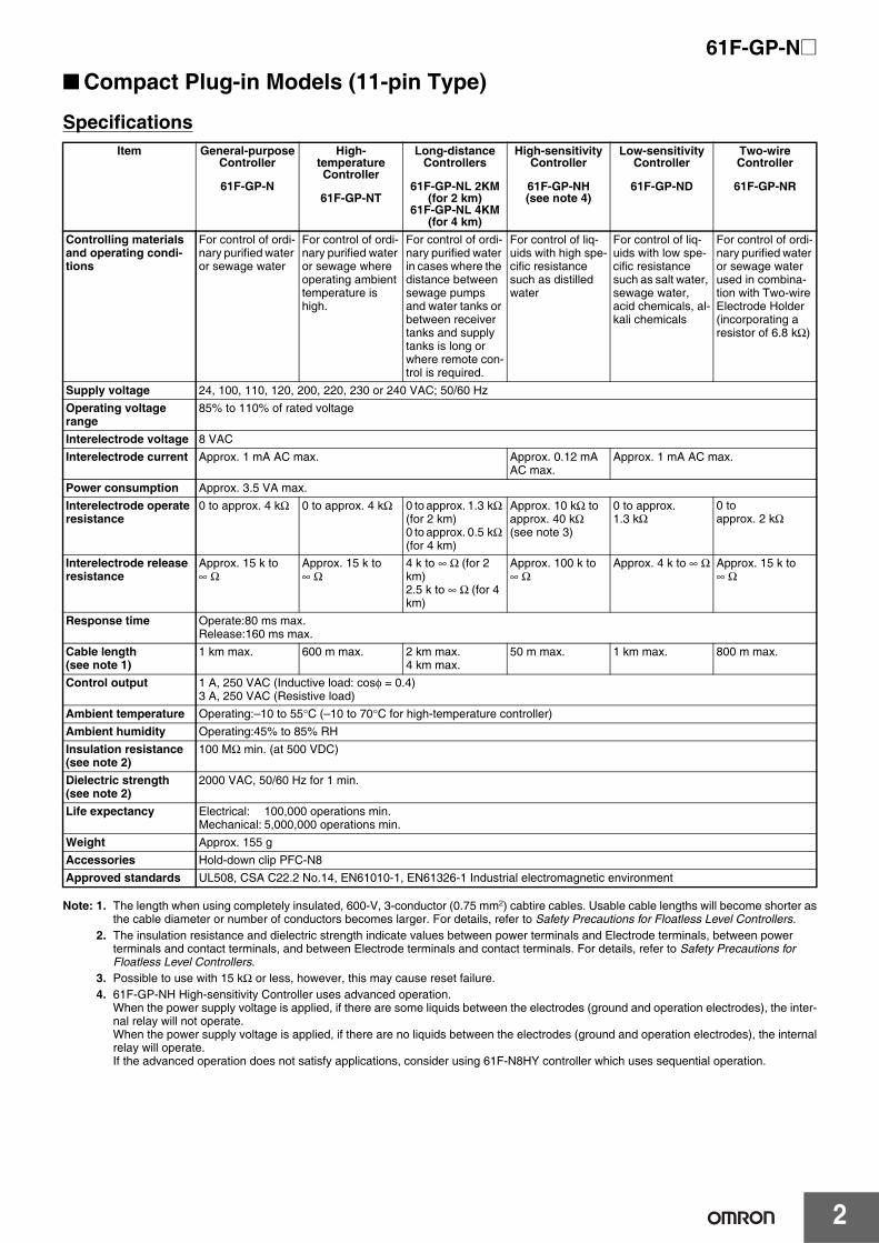
■ Compact Plug-in Models (11-pin Type)
Specifications
Note: 1. The length when using completely insulated, 600-V, 3-conductor (0.75 mm2) cabtire cables. Usable cable lengths will become shorter asthe cable diameter or number of conductors becomes larger. For details, refer to Safety Precautions for Floatless Level Controllers.
2. The insulation resistance and dielectric strength indicate values between power terminals and Electrode terminals, between power terminals and contact terminals, and between Electrode terminals and contact terminals. For details, refer to Safety Precautions for Floatless Level Controllers.
3. Possible to use with 15 kΩ or less, however, this may cause reset failure.4. 61F-GP-NH High-sensitivity Controller uses advanced operation.
When the power supply voltage is applied, if there are some liquids between the electrodes (ground and operation electrodes), the inter-nal relay will not operate.When the power supply voltage is applied, if there are no liquids between the electrodes (ground and operation electrodes), the internalrelay will operate. If the advanced operation does not satisfy applications, consider using 61F-N8HY controller which uses sequential operation.
Item General-purpose Controller
61F-GP-N
High-temperature Controller
61F-GP-NT
Long-distance Controllers
61F-GP-NL 2KM (for 2 km)
61F-GP-NL 4KM (for 4 km)
High-sensitivity Controller
61F-GP-NH (see note 4)
Low-sensitivity Controller
61F-GP-ND
Two-wire Controller
61F-GP-NR
Controlling materials and operating condi-tions
For control of ordi-nary purified water or sewage water
For control of ordi-nary purified water or sewage where operating ambient temperature is high.
For control of ordi-nary purified water in cases where the distance between sewage pumps and water tanks or between receiver tanks and supply tanks is long or where remote con-trol is required.
For control of liq-uids with high spe-cific resistance such as distilled water
For control of liq-uids with low spe-cific resistance such as salt water, sewage water, acid chemicals, al-kali chemicals
For control of ordi-nary purified water or sewage water used in combina-tion with Two-wire Electrode Holder (incorporating a resistor of 6.8 kΩ)
Supply voltage 24, 100, 110, 120, 200, 220, 230 or 240 VAC; 50/60 HzOperating voltage range
85% to 110% of rated voltage
Interelectrode voltage 8 VACInterelectrode current Approx. 1 mA AC max. Approx. 0.12 mA
AC max.Approx. 1 mA AC max.
Power consumption Approx. 3.5 VA max.Interelectrode operate resistance
0 to approx. 4 kΩ 0 to approx. 4 kΩ 0 to approx. 1.3 kΩ (for 2 km)0 to approx. 0.5 kΩ (for 4 km)
Approx. 10 kΩ to approx. 40 kΩ (see note 3)
0 to approx. 1.3 kΩ
0 to approx. 2 kΩ
Interelectrode release resistance
Approx. 15 k to ∞ Ω
Approx. 15 k to ∞ Ω
4 k to ∞ Ω (for 2 km)2.5 k to ∞ Ω (for 4 km)
Approx. 100 k to ∞ Ω
Approx. 4 k to ∞ Ω Approx. 15 k to ∞ Ω
Response time Operate:80 ms max.Release:160 ms max.
Cable length (see note 1)
1 km max. 600 m max. 2 km max.4 km max.
50 m max. 1 km max. 800 m max.
Control output 1 A, 250 VAC (Inductive load: cosφ = 0.4)3 A, 250 VAC (Resistive load)
Ambient temperature Operating:–10 to 55°C (–10 to 70°C for high-temperature controller)Ambient humidity Operating:45% to 85% RHInsulation resistance (see note 2)
100 MΩ min. (at 500 VDC)
Dielectric strength (see note 2)
2000 VAC, 50/60 Hz for 1 min.
Life expectancy Electrical: 100,000 operations min.Mechanical: 5,000,000 operations min.
Connect terminal 1 to the contactor’s coil terminal.
Note: The power supply depends on the specifications of the model.
Connections
E1
E2
E3
P
Water supply
(Indicator ON)Pump OFF
Pump ON (Indicator OFF)
The pump stops when the water level reaches E1 (indicator ON) and starts when the water level drops below E2 (indicator OFF).
Principles of Operation
E1
E2
E3
Water drainage
(Indicator ON)
Pump OFF
Pump ON
(Indicator OFF)
P
The pump starts when the water level reaches E1 (indicator ON) and stops when the water level drops below E2 (indicator OFF).
Principles of Operation
5
61F-GP-N@
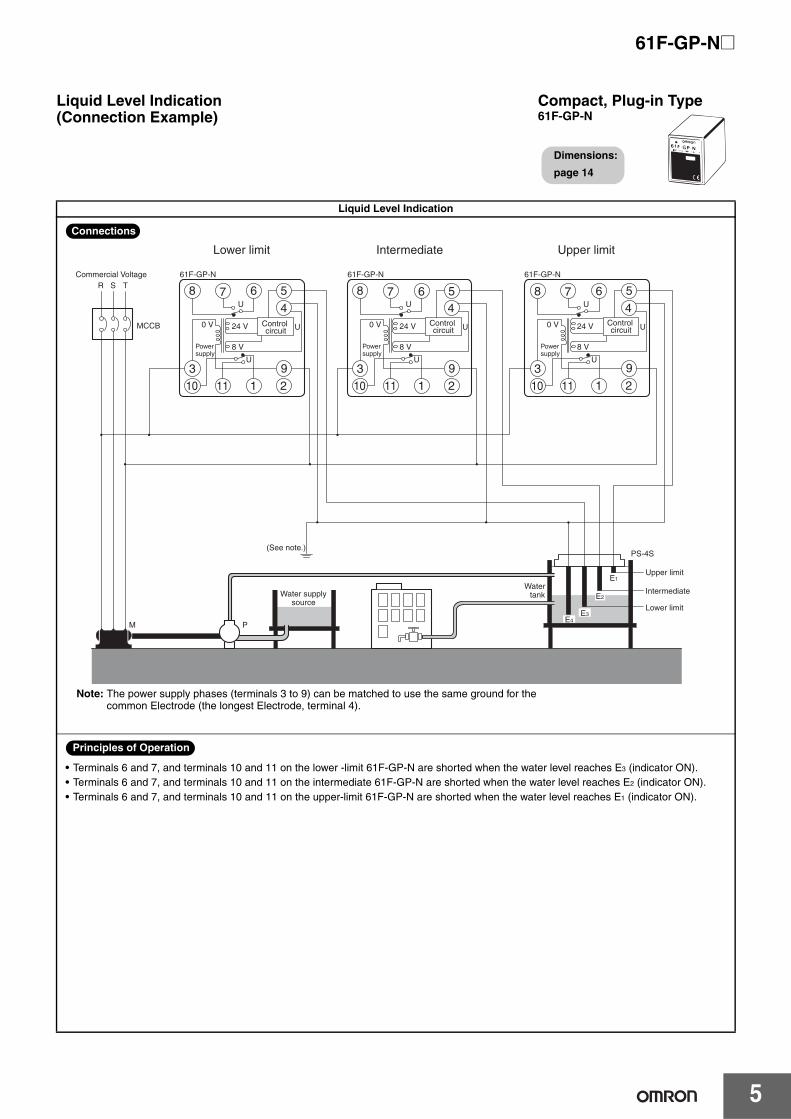
Liquid Level Indication
Liquid Level Indication (Connection Example)
Compact, Plug-in Type61F-GP-N
Dimensions:
page 14
E1
E2
E3E4
Water supplysource
Intermediate
Upper limit
Lower limit
MCCB
R S
M
TCommercial Voltage
P
PS-4S
U
U
61F-GP-N
Lower limit Intermediate Upper limit
5678
4
8 VPowersupply
Powersupply
Powersupply
0 V 24 V
103 9
1 211
Control circuit
U
U
U
61F-GP-N
56784
8 V
0 V 24 V
103 9
1 211
Control circuit
U
U
U
61F-GP-N
5678
4
8 V
0 V 24 V
103 9
1 211
Control circuit
U
(See note.)
Water tank
Note: The power supply phases (terminals 3 to 9) can be matched to use the same ground for the common Electrode (the longest Electrode, terminal 4).
Connections
• Terminals 6 and 7, and terminals 10 and 11 on the lower -limit 61F-GP-N are shorted when the water level reaches E3 (indicator ON).• Terminals 6 and 7, and terminals 10 and 11 on the intermediate 61F-GP-N are shorted when the water level reaches E2 (indicator ON).• Terminals 6 and 7, and terminals 10 and 11 on the upper-limit 61F-GP-N are shorted when the water level reaches E1 (indicator ON).
Principles of Operation
61F-GP-N@
6
Replacing 61F-G3N Functions
Replacing 61F-G3N Functions (Automatic Water Supply Control with Abnormal Water Increase and Water Shortage Alarms)
Compact, Plug-in Type61F-GP-N
Dimensions:
page 14
E1
E2
E4E5
Contactor
Water supply source
StopFull tank
StartWater shortage
MCCB
R S
M
TCommercial Voltage
Water shortage Pump control Full tank
P
PS-5S
E3
U3
U3
61F-GP-N
5678
4
8 VPowersupply
Powersupply
Powersupply
0 V 24 V
10
3 9
1 211
Control circuit
U3
U1
U1
61F-GP-N
56784
8 V
0 V 24 V
10
3 9
1 211
Control circuit
U1
U2
U2
61F-GP-N
5678
4
8 V
0 V 24 V
10
3 9
1 211
Control circuit
U2
BPL PL
(See note.)
Upper limitLower limit Alarm
Watertank
Motor protection relay
Note: The power supply phases (terminals 3 to 9) can be matched to use the same ground for the common Electrode (the longest Electrode, terminal 4).
Connections
E1
E3
E4
E5
Upper limit
Lower limit
Pump OFF
Pump ON
(U1 indicator ON)
(U2 indicator ON)
(U2 indicator OFF)
(U3 indicator OFF)
BLH
BLL
PWater supply
E2
• The pump stops when the water level reaches E2 (U2 indicator ON) and starts when the water level drops below E3 (U2 indicator OFF).
• If the water level rises to E1 for any reason, the upper-limit indicator turns ON and the alarm sounds (U1 indicator ON). If the water level drops below E4 for any reason, the lower-limit indicator turns ON and the alarm sounds (U3 indicator OFF).
Principles of Operation
7
61F-GP-N@
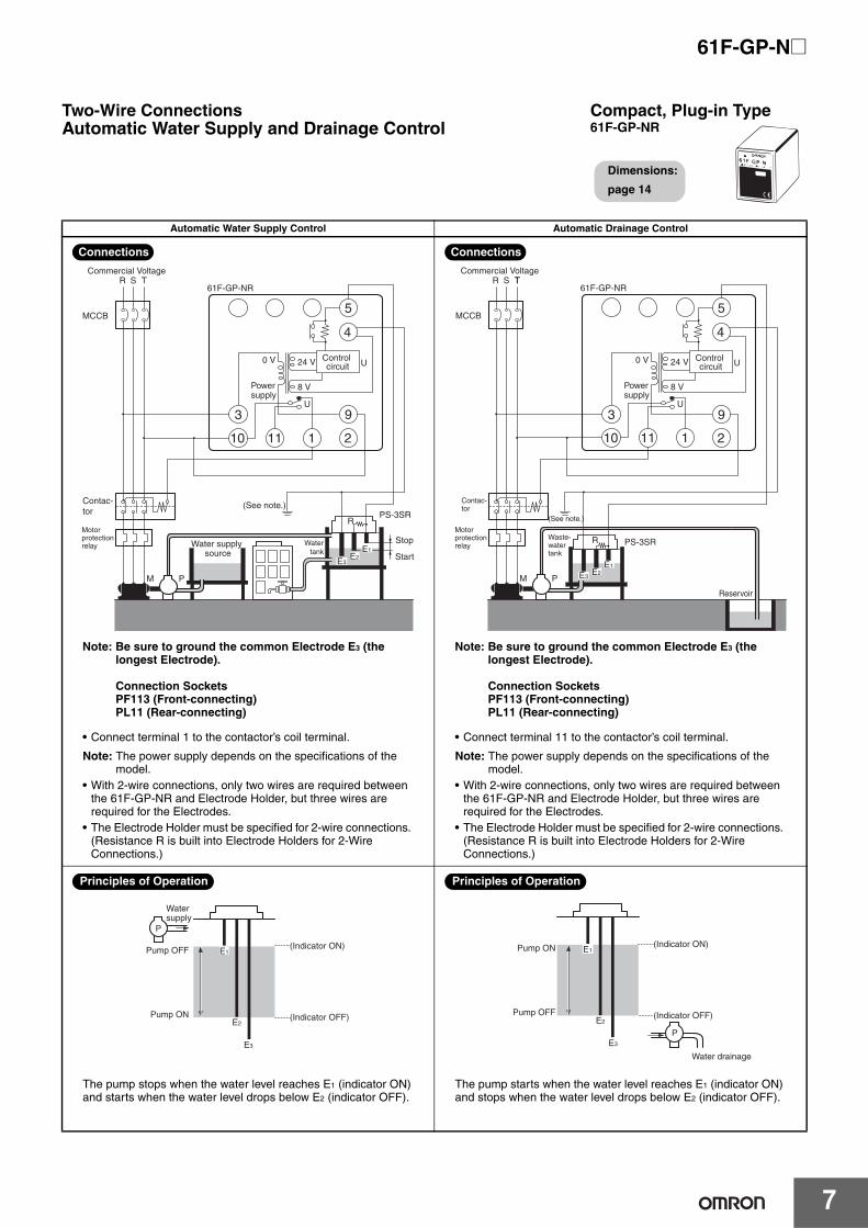
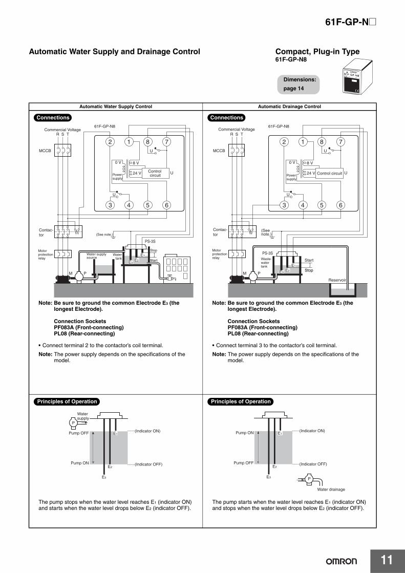
Automatic Water Supply Control Automatic Drainage Control
Two-Wire ConnectionsAutomatic Water Supply and Drainage Control
Compact, Plug-in Type61F-GP-NR
Dimensions:
page 14
E1E2E3
U
U
Water supply source
Stop
Start
MCCB
R S
M
TCommercial Voltage
61F-GP-NR
(See note.)
5
4
P
8 VPowersupply
0 V 24 V
PS-3SR
10
3 9
1 211
Control circuit
R
Contac-tor
Watertank
Motor protection relay
Note: Be sure to ground the common Electrode E3 (the longest Electrode).
• Connect terminal 11 to the contactor’s coil terminal.
Note: The power supply depends on the specifications of the model.
• With 2-wire connections, only two wires are required between the 61F-GP-NR and Electrode Holder, but three wires are required for the Electrodes.
• The Electrode Holder must be specified for 2-wire connections. (Resistance R is built into Electrode Holders for 2-Wire Connections.)
Connections
E1
E2
E3
P
Water supply
(Indicator ON)Pump OFF
Pump ON (Indicator OFF)
The pump stops when the water level reaches E1 (indicator ON) and starts when the water level drops below E2 (indicator OFF).
Principles of Operation
E1
E2
E3
Water drainage
(Indicator ON)
Pump OFF
Pump ON
(Indicator OFF)
P
The pump starts when the water level reaches E1 (indicator ON) and stops when the water level drops below E2 (indicator OFF).
Principles of Operation
61F-GP-N@
8
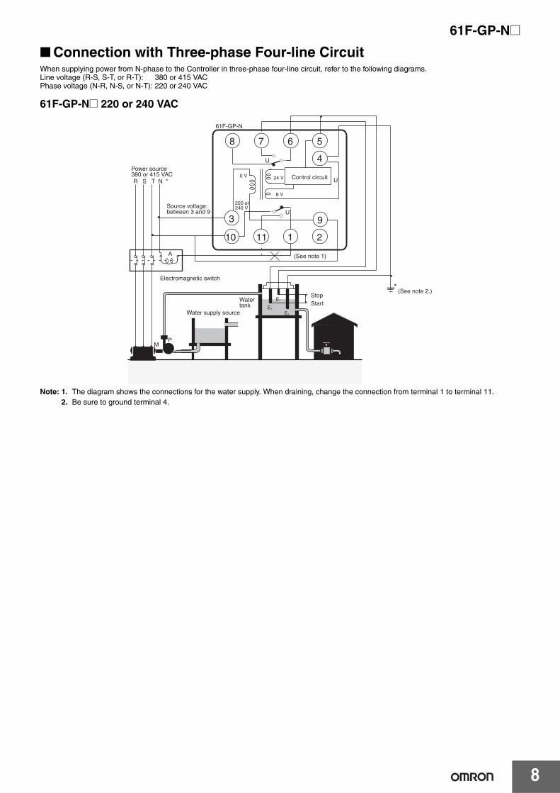
■ Connection with Three-phase Four-line CircuitWhen supplying power from N-phase to the Controller in three-phase four-line circuit, refer to the following diagrams.Line voltage (R-S, S-T, or R-T): 380 or 415 VACPhase voltage (N-R, N-S, or N-T): 220 or 240 VAC
61F-GP-N@ 220 or 240 VAC
Note: 1. The diagram shows the connections for the water supply. When draining, change the connection from terminal 1 to terminal 11.2. Be sure to ground terminal 4.
Power source380 or 415 VACR S T N *
M
Water tank
StopStart
E2
E3
E1
P
Electromagnetic switch
A
*
Water supply source
Source voltage: between 3 and 9
61F-GP-N
0 V
220 or 240 V
8 V
24 V Control circuit
U
U
78 6 5
211110
U
4
3 9
(See note 1)
(See note 2.)
9
61F-GP-N@
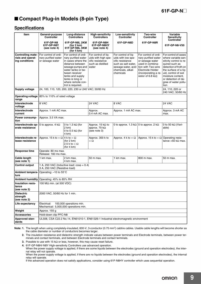
■ Compact Plug-in Models (8-pin Type)
Specifications
Note: 1. The length when using completely-insulated, 600-V, 3-conductor (0.75 mm2) cabtire cables. Usable cable lengths will become shorter asthe cable diameter or number of conductors becomes larger.
2. The insulation resistance and dielectric strength indicate values between power terminals and Electrode terminals, between power ter-minals and contact terminals, and between Electrode terminals and contact terminals.
3. Possible to use with 15 kΩ or less, however, this may cause reset failure.4. 61F-GP-N8H/-N8Y High-sensitivity Controllers use advanced operation.
When the power supply voltage is applied, if there are some liquids between the electrodes (ground and operation electrodes), the inter-nal relay will not operate.When the power supply voltage is applied, if there are no liquids between the electrodes (ground and operation electrodes), the internalrelay will operate. If the advanced operation does not satisfy applications, consider using 61F-N8HY controller which uses sequential operation.
Item General-purpose Controller
61F-GP-N861F-GP-N8Y (see note 4)
Long-distance Controllers
61F-GP-N8L 2KM (for 2 km)
61F-GP-N8L 4KM (for 4 km)
High-sensitivity Controllers
61F-GP-N8H61F-GP-N8HY(see note 4)
Low-sensitivity Controller
61F-GP-N8D
Two-wire Controller
61F-GP-N8R
Variable Sensitivity Controller
61F-GP-N8-V50
Controlling mate-rials and operat-ing conditions
For control of ordi-nary purified water or sewage water
For control of ordi-nary purified water in cases where the distance between sewage pumps and water tanks or be-tween receiver tanks and supply tanks is long or where remote con-trol is required.
For control of liq-uids with high spe-cific resistance such as distilled water
For control of liq-uids with low spe-cific resistance such as salt water, sewage water, acid chemicals, alkali chemicals
For control of ordi-nary purified water or sewage water used in combina-tion with Two-wire Electrode Holder (incorporating a re-sistor of 6.8 kΩ)
For control of cases where variable sen-sitivity control is re-quired such as detection of froth on the surface of a liq-uid, control of soil moisture content, or detection of de-gree of water pollu-tion
Supply voltage 24, 100, 110, 120, 200, 220, 230 or 240 VAC; 50/60 Hz 24, 110, 220 or 240 VAC; 50/60 Hz
Operating voltage range
85% to 110% of rated voltage
Interelectrode voltage
8 VAC 24 VAC 8 VAC 24 VAC
Interelectrode current
Approx. 1 mA AC max. Approx. 0.4 mA AC max.
Approx. 1 mA AC max. Approx. 3 mA AC max.
Power consump-tion
Approx. 3.5 VA max.
Interelectrode op-erate resistance
0 to approx. 4 kΩ 0 to 1.3 kΩ (for 2 km)0 to 0.5 kΩ (for 4 km)
Approx. 15 kΩ to approx. 70 kΩ (see note 3)
0 to approx. 1.3 kΩ 0 to approx. 2 kΩ 0 to 50 kΩ (Vari-able)
Interelectrode re-lease resistance
Approx. 15 k to ∞ Ω 4 k to ∞ Ω (for 2 km)2.5 k to ∞ Ω (for 4 km)
Approx. 300 k to ∞ Ω
Approx. 4 k to ∞ Ω Approx. 15 k to ∞ Ω Operating resis-tance +50 kΩ max.
Response time Operate: 80 ms max.Release: 160 ms max.
Cable length (see note 1)
1 km max. 2 km max.4 km max.
50 m max. 1 km max. 800 m max. 50 m max.
Control output 1 A, 250 VAC (Inductive load: cosφ = 0.4)3 A, 250 VAC (Resistive load)
Ambient tempera-ture
Operating: –10 to 55°C
Ambient humidity Operating: 45% to 85% RHInsulation resis-tance (see note 2)
100 MΩ min. (at 500 VDC)
Dielectric strength (see note 2)
2000 VAC, 50/60 Hz for 1 min.
Life expectancy Electrical: 100,000 operations min.Mechanical: 5,000,000 operations min.
• Connect terminal 3 to the contactor’s coil terminal.
Note: The power supply depends on the specifications of the model.
Connections
E1
E2
E3
P
Watersupply
(Indicator ON)Pump OFF
Pump ON (Indicator OFF)
The pump stops when the water level reaches E1 (indicator ON) and starts when the water level drops below E2 (indicator OFF).
Principles of Operation
E1
E2
E3
Water drainage
(Indicator ON)
Pump OFF
Pump ON
(Indicator OFF)
P
Principles of Operation
The pump starts when the water level reaches E1 (indicator ON) and stops when the water level drops below E2 (indicator OFF).
61F-GP-N@
12
Water Supply Automatic Drainage
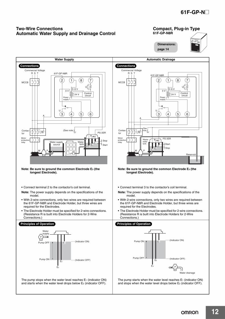
Two-Wire ConnectionsAutomatic Water Supply and Drainage Control
Compact, Plug-in Type61F-GP-N8R
Dimensions:
page 14
E1E2
E3
U
U
A
Water supply source
Stop
Start
MCCB
R S
M
T 61F-GP-N8R
7812
P
8 V0 V
24 V
PS-3SR
3 5 64
Controlcircuit
R
(See note.)
Watertank
Contac-tor
Commercial Voltage
Powersupply
Motor protection relay
Note: Be sure to ground the common Electrode E3 (the longest Electrode).
• Connect terminal 2 to the contactor’s coil terminal.
Note: The power supply depends on the specifications of the model.
• With 2-wire connections, only two wires are required between the 61F-GP-N8R and Electrode Holder, but three wires are required for the Electrodes.
• The Electrode Holder must be specified for 2-wire connections. (Resistance R is built into Electrode Holders for 2-Wire Connections.)
Connections
E2E3
U
U
A
Reservoir
MCCB
R S
M
T61F-GP-N8R
(See note.)
7812
P
R
8 V0 V
24 V
PS-3SR
3 5 64
Control circuit
Stop
StartE1
Contac-tor
Commercial Voltage
Powersupply
Motor protection relay
Waste-water tank
Note: Be sure to ground the common Electrode E3 (the longest Electrode).
• Connect terminal 3 to the contactor’s coil terminal.
Note: The power supply depends on the specifications of the model.
• With 2-wire connections, only two wires are required between the 61F-GP-N8R and Electrode Holder, but three wires are required for the Electrodes.
• The Electrode Holder must be specified for 2-wire connections. (Resistance R is built into Electrode Holders for 2-Wire Connections.)
Connections
E1
E2
E3
P
Watersupply
(Indicator ON)Pump OFF
Pump ON (Indicator OFF)
The pump stops when the water level reaches E1 (indicator ON) and starts when the water level drops below E2 (indicator OFF).
Principles of Operation
E1
E2
E3
Water drainage
(Indicator ON)
Pump OFF
Pump ON
(Indicator OFF)
P
The pump starts when the water level reaches E1 (indicator ON) and stops when the water level drops below E2 (indicator OFF).
Principles of Operation
13
61F-GP-N@
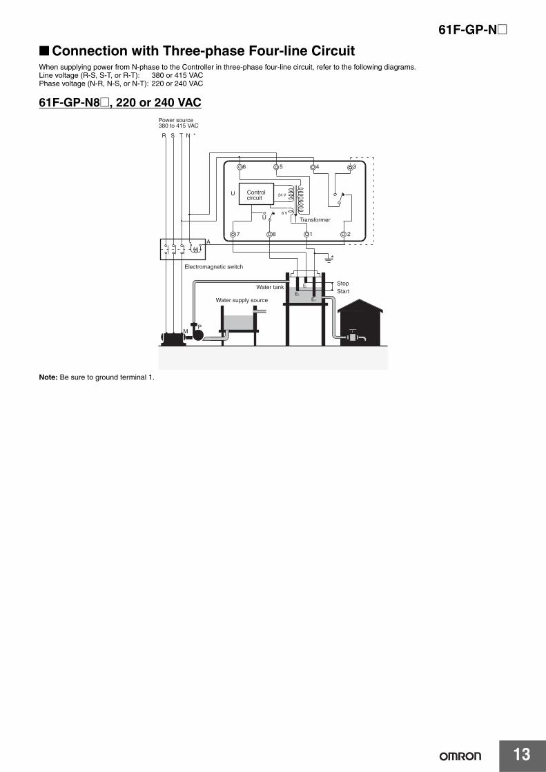
■ Connection with Three-phase Four-line CircuitWhen supplying power from N-phase to the Controller in three-phase four-line circuit, refer to the following diagrams.Line voltage (R-S, S-T, or R-T): 380 or 415 VACPhase voltage (N-R, N-S, or N-T): 220 or 240 VAC
61F-GP-N8@, 220 or 240 VAC
Note: Be sure to ground terminal 1.
Power source380 to 415 VAC
R S T N *
M
Water tankStopStartE2
E3
E1
P
6
Electromagnetic switch
Transformer
4 3
7
5
1 2
U
24 V
8 V
A
*
U Control circuit
8
Water supply source
61F-GP-N@
14
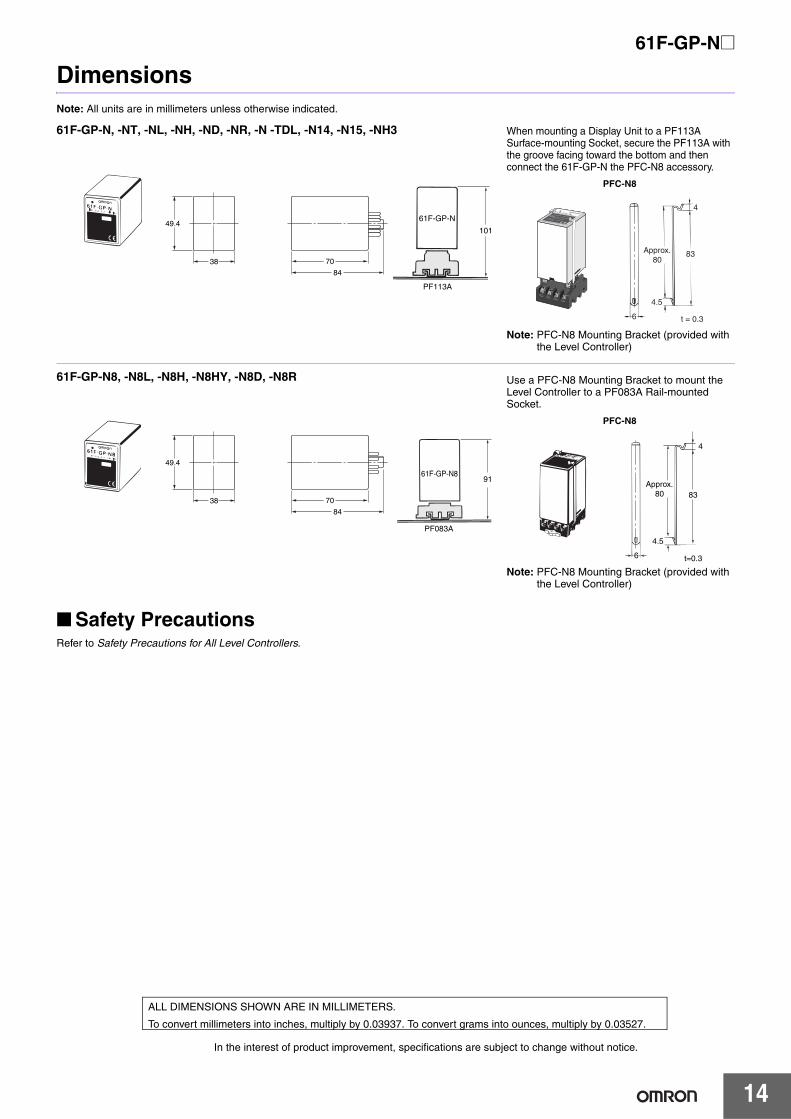
DimensionsNote: All units are in millimeters unless otherwise indicated.
■ Safety PrecautionsRefer to Safety Precautions for All Level Controllers.
49.4
38 70
84
61F-GP-N
PF113A
101
61F-GP-N, -NT, -NL, -NH, -ND, -NR, -N -TDL, -N14, -N15, -NH3 When mounting a Display Unit to a PF113A Surface-mounting Socket, secure the PF113A with the groove facing toward the bottom and then connect the 61F-GP-N the PFC-N8 accessory.
PFC-N8
Note: PFC-N8 Mounting Bracket (provided with the Level Controller)
t = 0.3
4.5
83
4
6
Approx. 80
I
I
FREQ. : 50/60HzSECONDARY
:8 VACVOLTA E
38 70
84
49.4
61F-GP-N8
PF083A
91
61F-GP-N8, -N8L, -N8H, -N8HY, -N8D, -N8R Use a PFC-N8 Mounting Bracket to mount the Level Controller to a PF083A Rail-mounted Socket.
PFC-N8
Note: PFC-N8 Mounting Bracket (provided with the Level Controller)
83
4
4.5
t=0.36
Approx.80
In the interest of product improvement, specifications are subject to change without notice.
ALL DIMENSIONS SHOWN ARE IN MILLIMETERS.
To convert millimeters into inches, multiply by 0.03937. To convert grams into ounces, multiply by 0.03527.
Terms and Conditions Agreement Read and understand this catalog. Please read and understand this catalog before purchasing the products. Please consult your OMRON representative if you have any questions or comments. Warranties. (a) Exclusive Warranty. Omron’s exclusive warranty is that the Products will be free from defects in materials and workmanship for a period of twelve months from the date of sale by Omron (or such other period expressed in writing by Omron). Omron disclaims all other warranties, express or implied. (b) Limitations. OMRON MAKES NO WARRANTY OR REPRESENTATION, EXPRESS OR IMPLIED, ABOUT NON-INFRINGEMENT, MERCHANTABILITY OR FITNESS FOR A PARTICULAR PURPOSE OF THE PRODUCTS. BUYER ACKNOWLEDGES THAT IT ALONE HAS DETERMINED THAT THE PRODUCTS WILL SUITABLY MEET THE REQUIREMENTS OF THEIR INTENDED USE. Omron further disclaims all warranties and responsibility of any type for claims or expenses based on infringement by the Products or otherwise of any intellectual property right. (c) Buyer Remedy. Omron’s sole obligation hereunder shall be, at Omron’s election, to (i) replace (in the form originally shipped with Buyer responsible for labor charges for removal or replacement thereof) the non-complying Product, (ii) repair the non-complying Product, or (iii) repay or credit Buyer an amount equal to the purchase price of the non-complying Product; provided that in no event shall Omron be responsible for warranty, repair, indemnity or any other claims or expenses regarding the Products unless Omron’s analysis confirms that the Products were properly handled, stored, installed and maintained and not subject to contamination, abuse, misuse or inappropriate modification. Return of any Products by Buyer must be approved in writing by Omron before shipment. Omron Companies shall not be liable for the suitability or unsuitability or the results from the use of Products in combination with any electrical or electronic components, circuits, system assemblies or any other materials or substances or environments. Any advice, recommendations or information given orally or in writing, are not to be construed as an amendment or addition to the above warranty. See http://www.omron.com/global/ or contact your Omron representative for published information. Limitation on Liability; Etc. OMRON COMPANIES SHALL NOT BE LIABLE FOR SPECIAL, INDIRECT, INCIDENTAL, OR CONSEQUENTIAL DAMAGES, LOSS OF PROFITS OR PRODUCTION OR COMMERCIAL LOSS IN ANY WAY CONNECTED WITH THE PRODUCTS, WHETHER SUCH CLAIM IS BASED IN CONTRACT, WARRANTY, NEGLIGENCE OR STRICT LIABILITY. Further, in no event shall liability of Omron Companies exceed the individual price of the Product on which liability is asserted. Suitability of Use. Omron Companies shall not be responsible for conformity with any standards, codes or regulations which apply to the combination of the Product in the Buyer’s application or use of the Product. At Buyer’s request, Omron will provide applicable third party certification documents identifying ratings and limitations of use which apply to the Product. This information by itself is not sufficient for a complete determination of the suitability of the Product in combination with the end product, machine, system, or other application or use. Buyer shall be solely responsible for determining appropriateness of the particular Product with respect to Buyer’s application, product or system. Buyer shall take application responsibility in all cases. NEVER USE THE PRODUCT FOR AN APPLICATION INVOLVING SERIOUS RISK TO LIFE OR PROPERTY OR IN LARGE QUANTITIES WITHOUT ENSURING THAT THE SYSTEM AS A WHOLE HAS BEEN DESIGNED TO ADDRESS THE RISKS, AND THAT THE OMRON PRODUCT(S) IS PROPERLY RATED AND INSTALLED FOR THE INTENDED USE WITHIN THE OVERALL EQUIPMENT OR SYSTEM. Programmable Products. Omron Companies shall not be responsible for the user’s programming of a programmable Product, or any consequence thereof. Performance Data. Data presented in Omron Company websites, catalogs and other materials is provided as a guide for the user in determining suitability and does not constitute a warranty. It may represent the result of Omron’s test conditions, and the user must correlate it to actual application requirements. Actual performance is subject to the Omron’s Warranty and Limitations of Liability. Change in Specifications. Product specifications and accessories may be changed at any time based on improvements and other reasons. It is our practice to change part numbers when published ratings or features are changed, or when significant construction changes are made. However, some specifications of the Product may be changed without any notice. When in doubt, special part numbers may be assigned to fix or establish key specifications for your application. Please consult with your Omron’s representative at any time to confirm actual specifications of purchased Product. Errors and Omissions. Information presented by Omron Companies has been checked and is believed to be accurate; however, no responsibility is assumed for clerical, typographical or proofreading errors or omissions.
2015.8
In the interest of product improvement, specifications are subject to change without notice.
OMRON Corporation Industrial Automation Company http://www.ia.omron.com/
(c)Copyright OMRON Corporation 2015 All Right Reserved.