54
Michigan Department of Environmental Quality Water Bureau Drinking Water & Environmental Health Section Well Construction Unit March 2005 FLOWING WELL HANDBOOK

Michigan Department of Environmental Quality Water Bureau
Drinking Water & Environmental Health Section Well Construction Unit
March 2005
FLOWING WELL HANDBOOK

MICHIGAN FLOWING WELL HANDBOOK
Table of Contents Page Introduction…………………………………………………………………………..……………….…… 1 Flowing Well Occurrence ………………………………………………………………………… 2 Artesian Well Characteristics ……………….…………………………..…………………. 3 Decline of Artesian Head ………….……………………………………………………………. 8 Damage from Flow Breakouts ………………………………………………………………… 9 Case Histories ………………………………………………………………………………………….. 10 Historical Legal Aspects …………………………………………………………………………. 13 Well Construction Code Requirements …………………………………………….…… 14 Deviation to Allow Flowing Well Discharge……………………………………….…. 15 Discharge Control ……………………………………………………………………………………... 16 Existing Flowing Wells ……………………………………………………………………………… 17 Flow Control Within Casing ……………………………………………………………………… 18 Venting of Casing …………………………………………………………………………………..….. 26 Water System Configurations ………………………………………………………………. 26 Well Construction Methods…………………………………………………………………….. 27 Inflatable Packers ..…………………………………………….…………………………………….. 29 Grouting Materials …………………………………………………………………………………….. 29 Artesian Head Considerations ………………………………………………………………… 32 Measuring Artesian Head ……………………………………………………………………….. 33 Downhole Hydraulic Head Pressure ………………………………………………………. 34 Flow Around Casing …………………………………………………………………………….……… 34 Annular Flow Correction Procedures.…………………………………………………..… 35 Disinfection of Flowing Wells …………………………………………………………………. 38 Flow Discharge Piping and Cross Connection Hazards …………………….… 38 Plugging Abandoned Flowing Wells …………………………………………………………. 39 LHD Permits for Flowing Well Areas ………………………………………………….… 41 Other Permits …………………………………………………………………………………………… 41 References ………………………………………………………………………………………………….. 42 Appendices: A - Hydrostatic Pressures for Flowing Artesian Wells 44 B - Flow Rate Charts ………………………………………………………….. 45 C - Flowing Well Discharge Deviation Form ………………….. 47 D - Flowing Wells – Damages Act ………………………………….... 48 E - Flowing Well Worksheet ……………………………………………. 49

List of Tables and Diagrams Page Figure 1 – Geologically Controlled Flowing Wells ………………………………… 5 Figure 2 – Topographically-Controlled Flowing Wells ………………………… 7 Figure 3 – Flow Control Using Flowing Well Pitless Unit …………………… 19 Figure 4 – Flow Control Using Drawdown Seals …………………………………… 20 Figure 5 – Flow Discharge Piping at Wellhead ……………………………………. 21 Figure 6 – Flow Control Using Elevated Flow Tank ……………………………… 22 Figure 7 – Unapproved Annular Flow Discharge Piping ………………………. 23 Figure 8 – Unapproved Buried Flow Discharge Piping with Check Valve ………………………………………………………………. 24 Figure 9 – Unapproved Buried Flow Discharge Piping with Submerged Inlet …………………………………………………….. 25 Hydrostatic Pressures of Common Grouts ……..……………………………………. 30 Hydrostatic Pressures for Flowing Artesian Wells …………….….…………. 44 Flow Rate Charts ……………………………………………………………………….………………. 45
Acknowledgement The author expresses his sincere gratitude to those individuals within the Michigan Department of Environmental Quality (DEQ), Water Division who diligently reviewed the manuscript and provided constructive technical advice. Special thanks to Mr. Brant Fisher, Environmental Engineer, Wellhead Protection Unit, DEQ, whose hydrogeological expertise contributed greatly toward completion of this handbook. Ms. Anita Ladouceur, Environmental Sanitarian, Well Construction Unit, DEQ applied her creative graphic arts skills to prepare the diagrams. Mr. James McEwan, Abandoned Well Management Program Coordinator, DEQ provided valuable input in the section devoted to plugging abandoned flowing wells. The Michigan Flowing Well Handbook was prepared and published by the Michigan Department of Environmental Quality, Water Bureau, Drinking Water and Environmental Health Section, Well Construction Unit, P.O. Box 30630, Lansing, MI 48909-8130, phone 517-241-1377, fax 517-241-1328. Additional water well information can be obtained through the department’s website at www.michigan.gov/deq.

1
MICHIGAN FLOWING WELL HANDBOOK
by Michael S. Gaber, R.S., M.P.H., Chief, Well Construction Unit Michigan Department of Environmental Quality, Water Bureau
Drinking Water and Environmental Health Section
INTRODUCTION Flowing artesian wells are water wells where the pressure in the aquifer (water-bearing geologic formation) forces ground water above the ground surface so that the well will flow without a pump. Several methods are used to construct flowing wells and to control the discharge of water from the well. To ensure that the artesian properties of aquifers are preserved and that environmental and personal property damage do not occur, water well contractors need to be fully prepared when completing wells in areas where flowing wells are encountered. Understanding flowing wells is important for health officials and others who evaluate the sanitary integrity of drinking water supplies. Water storage and distribution piping arrangements on existing flowing well systems vary considerably from conventional water well systems. Inspectors conducting sanitary surveys of older flowing well systems may encounter cross connections that pose a health hazard to users of the water system. This handbook is intended to serve as guidance for the construction, plugging, and evaluation of flowing wells, and to accomplish the following goals:
A. Help preserve the artesian properties of aquifers. B. Conserve ground water resources. C. Prevent property damage and adverse impacts to receiving waters. D. Improve industry flowing well construction practices. E. Achieve compliance with state well construction code regulations.
A perception that Michigan’s ground water supply was limitless, combined with poor well casing sealing practices when flowing wells were constructed in the past, resulted in the wasteful and unnecessary discharge of an enormous amount of ground water. If all of the flowing wells drilled in Michigan in 2001 were allowed to discharge to surface without any volume reduction, about 28 million gallons of ground water would be released from artesian aquifers each day. Uncontrolled discharges from new flowing wells would amount to over 30,000 acre-feet of ground water being wasted annually in Michigan.

2
Diligent statewide enforcement of existing flowing well discharge control regulations helps ensure that the hydraulic properties of artesian aquifers are preserved for future generations. The areas of Michigan where flowing wells occur need to be delineated so that county well permit programs become useful tools to regulate flowing well construction practices. FLOWING WELL OCCURRENCE Flowing wells are found throughout Michigan and can originate from aquifers occurring in either glacial drift or bedrock. About 200 flowing well districts were identified in the Lower Peninsula of Michigan during ground water investigations conducted in the early 1900’s (Leverett, et al., 1906, 1907). Data from the water well record data base at the Michigan Department of Environmental Quality (MDEQ), shows that from June 2001 through June 2002, about 450 flowing wells were drilled in Michigan (About 3 percent of the new water wells drilled). The average flow rate from the newly drilled wells, before flow control devices were installed, was 42 gallons per minute (gpm). Forty of the wells had flow rates of 100 gpm or more. A well drilled in Section 34, Klacking Township, Ogemaw County in December 2001, using a cable tool rig, produced a geyser of water 12 feet above the top of the 4-inch casing. The well drilling contractor reported the flow rate to be 1,000 gpm. Some of the largest flow rates reported by Leverett et al., (1907) were from two 2-inch diameter wells in Rose City, Ogemaw County. These wells reportedly flowed at 270 and 272 gpm and in combination served 25 families. In 1907, the total flow from 20 Rose City wells was 2,290 gpm or 10,000 gallons per day per resident, which was the highest daily per capita water usage for any Michigan city. In 1986, large volume, high head flows were encountered in the village of Cedar, Solon Township, Leelanau County, when several drinking water wells were replaced through a state-funded ground water contamination remediation program. A Michigan Department of Public Health official recorded shut-in pressures of 30 pounds per square inch (psi) (equivalent to a piezometric level of 69.3 feet above surface) from the 4 inch wells, which ranged in depth from 300 to 330 feet. The 200 to 450 gpm discharges were successfully controlled by installing pitless units with flowing well spools. The pressure at the wellhead was so great that when a backhoe bucket was used to push the pitless unit spool into place, the front end of the backhoe was lifted off the ground. The problem was overcome by installing a valved blow-off on the casing below the pitless unit connection, which was opened temporarily during the pitless unit installation.

3
Allen (1977), reports an artesian head of 84 feet (equivalent to 36 psi pressure at the ground surface) from a 215 foot (ft) deep Silurian bedrock well in Section 29 of Garfield Township, near the village of Naubinway in Mackinaw County. This is thought to be the highest reported artesian head in Michigan. Two large flowing wells were reported by Brown (1970) and Swanson (1991). In 1969, a 12-inch well drilled to a depth of 334 feet was completed at Fort St. James, British Columbia, Canada. The well flowed 4,200 gpm and had a shut-in head pressure of 52 psi (equivalent to 120 feet of artesian head) (Brown, 1970). A phenomenal well to serve a commercial catfish farm in Alvin, Texas was completed in 1991. Nearly 1,600 feet of 30-inch steel casing pipe was pressure cemented and upon completion a 21,000 gpm water stream shot 25 feet in the air (Swanson, 1991). The force of the water in the Texas well was so great that it was able to lift an 85 lb. piece of a broken reaming bit out of the well. Flowing wells have intrigued mankind for centuries. This point was illustrated by Freeze and Cherry (1979), who stated: “Flowing wells (along with springs and geysers) symbolize the presence and mystery of subsurface water, and as such they have always evoked considerable public interest.” According to Davis and DeWiest (1966), the widespread search for artesian water that occurred after the completion of flowing wells in Flanders (now Belgium and the Netherlands) around 1100 A.D., and later in the 18th century in the northern France province of Artois, Western England, and Northern Italy, was responsible for stimulating the advancement of water well drilling technology. Throughout Michigan, flowing wells have become local attractions. Among the northern Michigan towns and villages where flowing wells are abundant are West Branch, Rose City (Ogemaw County), Cedar (Leelanau County), Indian River (Cheboygan County), Onekama (Manistee County), Conway, Oden , Alanson, (Emmet County), Naubinway (Mackinaw County), and Rapid River (Delta County). Trout hatcheries and other fish rearing ponds have developed in some locations because of the availability of flowing artesian wells. In the late 19th century and early 20th century, flowing wells attracted visitors to Michigan hotels and resorts that touted the therapeutic benefits of artesian mineral waters. Today, many flowing wells in roadside parks, campgrounds, and along road right-of-ways are sources of drinking water for visitors who stop by to fill water containers. ARTESIAN WELL CHARACTERISTICS In artesian wells, water rises within the well to a point above the top of the aquifer. If the water also rises above the ground surface, the well is called a “flowing well,” or “flowing artesian well.” All flowing wells are artesian, but not all
4
artesian wells are flowing wells. Within both confined and unconfined aquifers, the water level rises and falls in response to the volume of water within the aquifer pore space. Aquifer recharge events and withdrawal of ground water affect the water level. During pumping of a well in a confined formation, water flow to the well is the result of compression of the aquifer matrix and a lowering of the potentiometric surface. Because the water level of artesian aquifers can be influenced by barometric pressure, well owners occasionally report fluctuations of flow rates and/or turbidity production during stormy weather. Elevation and loading are two distinct hydrogeological forces that account for the development of flowing artesian wells. Artesian conditions can be either geologically-controlled or topographically-controlled. The classic explanation for flowing wells is the geologically-controlled scenario depicted in Figure 1.

- FIGURE 1 - GEOLOGICALLY-CONTROLLED FLOWING WELLS
Recharge area for artesian aquifer
Artesian well
Piezometric level
Water table well
Flowing artesian well
Stream
Ground surface
5

6
The well taps an aquifer that is confined because of an overlying layer of geologic material that has a lower hydraulic conductivity (or permeability). The impermeable layer is called an “aquicludes.” Another geologic unit that can create artesian conditions is a slightly permeable layer which transmits some water vertically, called an “aquitard.” Water within confined aquifers (artesian water) is separated from the atmosphere by the impermeable materials. A recharge area that is at an elevation higher than the well causes loading that creates the hydraulic head that pressurizes the water within the confined aquifer. The weight of the overlying aquiclude or aquitard also exerts pressure on the water. When the well casing penetrates through the impermeable materials and reaches the artesian aquifer, pressure is released and the water rises within the well casing as it seeks equilibrium with the elevation of the water at the aquifer’s recharge area. Topography can influence hydrogeological conditions in an area and can be the controlling factor in the production of flowing wells. In unconfined aquifers, flowing wells can occur when the well intake (screen) is deep enough to intercept a zone where the hydraulic head (or pressure) value is higher than the land surface (See Figure 2).

- FIGURE 2 - TOPOGRAPHICALLY – CONTROLLED FLOWING WELL
Unconfined aquifer condition
7

8
This typically occurs in ground water discharge areas, which are often lower areas near rivers and lakes, but can also occur in relatively flat terrains with no outcrop of the recharge area. The hydraulic head of ground water changes as it moves along flow paths from the recharge area toward the discharge area. The slope of the flow path and the resultant hydraulic head value are controlled by topography. As ground water moves along its flow path, it can travel deep below ground, where it lies beneath ground water having a lower hydraulic head. When a well is drilled into the high head zone, the resistance up the well casing is less than the resistance to water movement caused by the friction of the overlying soil. The ground water moves from the high head condition toward the low head condition and a flowing well is created. This condition is described more extensively in Freeze and Cherry (1979), Fetter (1988), and Riewe (1992). DECLINE OF ARTESIAN HEAD For decades before the 1994 revision of the Michigan well construction code, contractors’ field practices typically included allowing water to discharge freely from the well with little or no attempt to restrict the discharge rate. If well drilling contractors failed to get the casing sealed and water continued to flow around the casing after well completion, the driller sometimes installed an underdrain. The underdrain consisted of a gravel pocket surrounding the casing a few feet below grade to collect the annular space flow. A drain pipe carried water from the gravel to a receiving area (lower terrain, ditch, or surface water). Today, an underdrain on a new flowing well violates Michigan’s well construction code. Reduction of artesian head in the aquifer and loss of flow can result from uncontrolled discharge of artesian water from a flowing well. Neighboring wells can be adversely impacted by lowering of the water level within a confined aquifer. An example of this phenomenon occurred in Rose City, Ogemaw County, in 1989, after a 1,200 gpm flow broke out around the casing of a 65 year old abandoned 3-inch well. Nearby wells (<1/2 mile) stopped flowing and some residents had to install pumps in order to withdraw water from their wells where none were previously required. Leverett, et al. (1906, 1907) noted reports of artesian head decline or flow reduction in several flowing well districts and attributed the decline to several causes, including: (1) the wasteful discharge from artesian wells, (2) the overdevelopment of an aquifer (too many wells drilled), (3) casing split during driving, which allows leakage into upper strata, (4) accelerated corrosion of iron casing pipe due to high dissolved carbon dioxide, (5) imperfect driving of casing, which disturbs the overlying clay, (6) collapse of an uncased borehole, (7) clogging of the well strainer (screen), (8) sanding-in of open bottom wells, (9) children

9
placing obstructions into the open well casings, and 10) drought or subsurface dewatering of the well catchment area. Leverett observed that in rural areas it was common to find flowing wells running to waste in yards where gardens and lawns were suffering for lack of water. The 1906-1907 reports note that there was growing appreciation of the need to curtail flow discharges and use reducers or faucets to prevent waste. Allen (1974) compared Michigan’s flowing well districts recorded at the turn of the 20th century by Leverett, and others (1906, 1907), to wells existing in 1970. The comparison showed a probable decline of artesian head in glacial drift artesian aquifers and within the Marshall and Saginaw bedrock formations in central and southern Lower Michigan. Allen (1974) noted that in several counties in south-central Lower Michigan where flowing wells were common in 1900, few or no flowing wells were drilled from 1965-70. This suggested a probable artesian head decline in glacial drift aquifers in Allegan, Bay, Berrien, Clinton, Genesee, Gratiot, Ionia, Isabella, Kent, Lapeer, Lenawee, Monroe, Midland, Muskegon, Newaygo, Oakland, Oceana, Sanilac, St. Clair, Tuscola, Van Buren, and Washtenaw Counties. DAMAGE FROM FLOW BREAKOUTS Sealing the annular space surrounding the well casing is critical, since an ineffective seal or absence of a seal can result in the uncontrolled discharge of water on the outside of the well casing pipe. When ground water breaks out on the outside of the well casing, erosion of the confining geologic layer and other overlying materials can occur. The uncontrolled discharge of ground water from flowing wells can cause flooding of the well site and adjacent properties and damage to nearby structures. If the flowing well breakout is not promptly contained, silt, clay, gravel, sand, and drilling fluids can be carried along with the artesian ground water to the ground surface and eventually reach surface water. The chemical and physical characteristics of the ground water can alter the quality of the surface water and the habitat of aquatic organisms can be impacted. The colder water temperatures from a flowing well discharge can alter the habitat of warm water aquatic species. Once a flow breakout begins, the rate of the discharge can increase over time. Flow along the outside of the casing can quickly enlarge the borehole and form subsurface voids. A large volume of geologic material can erupt during a breakout or blowout and create unstable, hazardous conditions at the surface near the well site.

10
The failure of the casing/borehole seal that can occur during construction of the well or decades after completion, can be costly. Flowing well breakouts that occurred in Michigan from 1988 to 1998, cost between $7,000 and $60,000 to correct, with the average being $32,000. CASE HISTORIES Hillsdale County, 1999 Occasionally, a well drilling contractor encounters a stubborn flow in an area where flowing wells are not known to exist or where significantly smaller flows are expected. A local well driller was prepared for a low volume flow (nearby wells have 5 to 10 gpm flows), while drilling a household well in Section 10, Pittsford Township. A flow estimated at between 1,500 and 2,000 gpm erupted around the well casing. During the blowout, the upper 30 feet of borehole (initially 7 7/8 inches) enlarged to a diameter of 30 inches, washing large amounts of sediment into a nearby ditch. After several grouting attempts by the contractor, with assistance from other area well drillers, an oil-field service company was hired to cement the well. After three attempts, using thixotropic cement (with friction reducer and accelerator – slurry density of 16.5 lbs. per gallon) the annulus was successfully sealed and the well was saved. Over 1,400 sacks of cement and 90 sacks of bentonite were used and the total cost to contain the flow was over $33,000. Alcona County - 1996 In 1996, a major blowout of artesian water and drilling fluid occurred along the annulus of an existing 2-inch well and up the borehole of a new well under construction in Section 33, Gustin Township, Alcona County. The turbid discharge completely filled a trout pond on the property with clay and overflowed into a nearby trout stream. A milky brown plume extended downstream for two miles. An analysis of discharge samples from the well site (results given below) showed significantly higher levels of suspended solids, chloride, ammonia nitrogen and total phosphorus, than the background water quality of the river. Some pollutants (COD, nitrate + nitrite, sulfate, and TOC) were higher in the river background sample.
Test Well Discharge River Background Alkalinity 242 mg CaCO3/l 217 mg CaCO3/l Carbonate Alkalinity <5 mg CaCO3/l <5 mg CaCO3/l Bicarbonate Alkalinity 242 mg CaCO3/l 217 mg CaCO3/l Chloride 76 mg/l 8 mg/l

11
COD < 5 mg/l 16 mg/l Conductivity 649 umho/cm 415 umho/cm Nitrite .007 mg N/l .003 mg N/l Nitrate + Nitrite .010 mg N/l .030 mg N/l Ammonia .26 mg N/l .015 mg N/l Kjeldahl Nitrogen .57 mg N/l .39 mg N/l pH 8.05 8.20 Ortho Phosphate .025 mg P/l .005 mg P/l Total Phosphorus .21 mg/P/l .023 mg P/l Suspended Solids 450 mg/l 6 mg/l Total Dissolved Solids 380 mg/l 270 mg/l Sulfate 6 mg/l 8 mg/l TOC <5 mg/l <5 mg/l
An MDEQ surface water quality official concluded that the sediment and nutrient-loading from the well blowout could have contributed to enrichment of a nearby lake. During the well blowout, about 30,000 cubic feet of materials washed from the borehole. A concern raised by MDEQ officials was the possibility of further land subsidence because of instability caused by subterranean voids. A comparison between the volume of the washed-out materials and the volume of the plugging materials used (about 7,400 cu. ft. - grout for well plugging and gravel to fill in sinkhole that formed between the new and old well.) shows a deficit of 22,600 cubic (cu) ft. Killing the well and site restoration after the blowout cost the well drilling contractor about $60,000. In 1993, another flowing well blow out occurred in Section 33, Gustin Township, Alcona County. An overflow drain from an artesian well serving a mobile home suddenly began discharging turbidity into the Pine River. DEQ Surface Water Division personnel responded to complaints from residents about cement-colored water discharging into the river. A heavy deposit of sediment up to 8 inches deep was found in the outfall area. A local well driller cemented new casing into the well, which resolved the turbidity problem. Ogemaw County – 1989 A 3-inch abandoned flowing well on vacant property in Rose City began to discharge a large volume of turbid water into Houghton Creek. The well, which was thought to be about 70 years old, was seeping a small volume of water from around the casing. When the breakout occurred, the initial flow rate was measured at 1,200 gpm and a week later the flow was 800 gpm. The flow on the inside of the
12
casing was 90 gpm. The annular flow created a 10- to 12-inch diameter hole around the well casing. The well problem was discovered after 10 residents a few blocks away complained of pressure loss and two homes were completely without water. A local well driller who was replacing one of the wells noticed the head decline when he drilled into the artesian aquifer. He immediately suspected that a flowing well in the vicinity had broken out and eventually located the culprit well. In an attempt to control the flow, the owner hired a well driller to drive a large casing around the well. After about 60 feet of 8 inch pipe was installed, the owner instructed the driller to pull back and remove 20 feet of pipe, after which the owner dumped a 20 yard load of field stone around the 8 inch pipe. Attempts were made to seal the flow with bentonite grout, but the grout washed out. The placement of the field stone significantly complicated further correction efforts. The owner spent about $15,000 trying to stop the flow himself, but was unsuccessful. The owner’s correction plan included the following steps:
• A 10 ft. deep by 15 ft. wide hole was excavated around the well. • Continual dewatering of the excavation was done using a high capacity
centrifugal pump. • A one-foot layer of bentonite chips was poured over the bottom of the
excavation. • Using a crane, a 10 ft diameter circular steel plate “donut” with a 12-inch
riser pipe in the middle was installed over the well on top of the bentonite chips. The steel plate contained a hole through which three 4-inch diameter grout pipes were placed. A tractor tire was placed around the well to act as an O-ring to seal between the bentonite chips and the steel plate.
• Neat cement grout was pumped down the three grout pipes while ready-mixed concrete was dumped on top of the steel donut.
Unfortunately, the correction efforts failed when the dewatering pump malfunctioned. After 12 yards of concrete was poured, the impeller of the dewatering pump broke apart and the concrete washed into the creek. After the concrete was chipped from the interior of the pump and the impeller was replaced, the owner excavated around the outside of the steel donut and poured an additional 3 ft. of concrete (22 yards) over the old concrete and steel donut. Two percent calcium chloride was used as a concrete accelerator. Dewatering took place for 62 hours after the concrete was poured. When the dewatering pump was shut off and a cap was installed on the top of the riser pipe in the center of the steel donut, water gushed up around the perimeter of the concrete.

13
The frustrated landowner constructed a clay berm about 6 ft. high surrounding the well to form a pond with a water level about 4 ft higher than the original grade. The top of the steel riser pipe extending from the center of the steel donut is about a foot above the pond level. It was estimated that the water head of the elevated pond level would reduce the flow rate from the well to about 600 gpm Water from the pond discharges through a drain into the nearby creek. Alger County - 1989 A runaway annular flow occurred in 1989 in Section 15, Munising Township, Alger County, during the installation of a household well with a cable tool rig. The flow discharge, estimated at over 500 gpm, eroded an area 8 feet around the well that reached the home’s foundation. The owner placed 150 yards of gravel into the washout in an attempt to stabilize the area and protect his home. A cementing firm killed the flow with 400 sacks of cement. Oceana County - 1980 Another blowout, in Section 3, Greenwood Township, Oceana County in 1980, resulted in flooding of a house basement and foundation undermining that eventually caused condemnation of the dwelling. The 2-inch well initially served 5 homes without a pump. When the 150 gpm blowout occurred, the owner reported shaking and rumbling of the ground and recalled that when he jumped into the well pit, it was rocking like a boat. The well began leaking several years earlier and a 4-inch casing had been driven around the 2-inch casing to attempt to seal an annular flow. Both casings disappeared downhole during the blowout. Other incidents of flowing well leakage on the outside of the well casing, due to either a lack of grouting in the annular space surrounding the casing or ineffective grouting, are cited by Gaber and Fisher (1988). HISTORICAL LEGAL ASPECTS Some of the earliest water supply legislation in Michigan dealt with regulating the use of artesian wells. Act No. 190 of the Public Acts of 1889, limited the amount of water that could be discharged from an artesian water well, to the volume that would flow though a one-inch pipe, to the detriment or injury of any other well or wells, unless consent of well owner(s) was obtained. Act No. 107 of the Public Acts of 1905 (also known as the “Flowing Well Damages Act” (FWDA), currently under Act 236, P.A. 1961, being § 600.2941 of the Michigan Compiled Laws), declared any artesian well that was allowed to flow to waste in an unreasonable manner to the depletion or lowering of artesian head to the detriment or damage of other wells, to be a nuisance. The FWDA provides remedies for affected property owners and allowed courts to issue decrees that would establish the limit of the well

14
discharge. The FWDA makes a well owner liable for damages to wells where the water level has been lowered as a result of the owners flowing well running to waste in an unreasonable or unnecessary manner. The FWDA is included as Appendix D. Flowing wells were involved in two of the earliest ground water rights court decisions in Michigan. The case involving the Ann Arbor waterworks system was cited by Leverett, and others (1906, 1907) as an example of artesian head lowering due to withdrawal from a municipal well field that exceeded aquifer replenishment. Evidence from Schenk v. City of Ann Arbor, 1917, showed that the cessation of flow from the plaintiffs’ wells was caused by ground water withdrawal from the defendant’s test wells situated from ¾ to 1 mile away, and that upon completion of the tests the flows resumed. A flowing well known as the Magnetic Mineral Spring, in St. Louis, Gratiot County, was the subject of another water rights case, Bernard v. City of St. Louis, 1922. The defendants municipal well caused the plaintiff’s mineral water well to cease flowing, necessitating the installation of pumping equipment to extract the water. Legislation to regulate artesian wells by creating flowing wells districts was introduced by the Michigan Senate in 1970 (Senate Bill No. 1237), but was never enacted. The bill, intended to protect and conserve artesian water pressures, would have allowed landowners or the state health department to petition to establish flowing well districts after public hearings were held. Permits to install wells within a flowing well district would have enabled state regulators to establish well construction and workmanship practices and restrict the flow of water from the artesian wells within the districts. WELL CONSTRUCTION CODE REQUIREMENTS Regulations within the Groundwater Quality Control Rules (well code), adopted pursuant to Part 127, 1978 PA 368 (Act 368) as amended, address flowing well construction and control. The specific administrative rules that address flowing wells are R 325.1613(2)(h), R 325.1621(3)(c), R 325.1638, and R 325.1663(3), as follows: R 325.1621(3)(c) - requires that flowing wells be constructed, equipped, and
operated to prevent unnecessary discharge of water. R 325.1621(3)(a) - requires that a well be constructed to maintain existing natural
protection against the contamination of aquifers. Applying this regulation to artesian wells means that the geologic confining layers must be preserved during well construction and that any
15
breeches in the confining layer that are created during drilling are sealed.
R 325.1638(1) - requires that a well constructed in a location where flowing
artesian conditions are encountered or are expected to occur shall be grouted to protect the artesian aquifer, prevent erosion of the overlying geologic materials, and confine the flow to within the casing.
R 325.1638(2) - requires that discharge control be provided to conserve
groundwater and to prevent the loss of artesian pressure by preventing or reducing continuous discharges, unless a deviation is issued under R 325.1613. Flow control shall consist of any of the following:
A. Valved pipe connections. B. Watertight pump connections. C. Receiving tank set at an altitude corresponding to that of
the artesian head. D. Flowing well pitless adapter. E. Packer. F. Other method approved by the health officer. A flow discharge pipe, where installed, shall not be directly connected to a sewer or other source of contamination.
DEVIATION TO ALLOW FLOWING WELL DISCHARGE A flowing well that is constructed after April 21, 1994 (effective date of the well code revision) may be permitted to discharge water, if a deviation is issued by the health officer of a local health department, pursuant to the provisions of R 325.1613(2)(h) of the well code. Before a deviation can be issued, the well owner or the owner's representative (well driller) must demonstrate any of the following:
1. Control of the flow is not practical - In some rare situations, controlling a flow may not be practical. The degree of difficulty in controlling the flow is increased if site conditions include a high artesian head, a large flow rate, a thin or unstable confining layer, or a shallow depth to the top of the artesian aquifer. This deviation condition also applies to situations where a technically sound but unsuccessful attempt has been made to control the discharge.

16
2. Control of the flow will likely result in the production of sand or turbidity in the water - While most flowing wells in unconsolidated geologic formations are completed with well screens, there may be cases where the contractor is not able to install one due to excessive uphole pressure. In such cases, the discharge rate should be reduced to the lowest pumping rate that will not result in sand or turbidity. It should be recognized, however, that barometric pressure changes, which affect aquifer head, can occasionally result in turbidity production, regardless of flow control mechanisms. Turbidity production may also be caused by insufficient well development.
3. The discharge is for a beneficial use – such as:
A. Maintaining water levels in a pond used for irrigation, fire protection, fish rearing, recreation, wildlife enhancement, or other commercial
purpose.
B. Supplying a continuous flow of water for heating, cooling, industrial processes, irrigation, or power generation.
The Flowing Artesian Well Discharge Deviation form (See Appendix) may be used by local health departments for issuing deviations to R 325.1638 of the well code. Since many flowing wells are located near surface waters, the discharge of water from flowing wells frequently involves disposal into a lake, river, or stream. If the buried discharge line or spillway passes through a wetland, a soil erosion/sedimentation permit may be needed. Contact the local soil erosion/zoning office to find out whether a permit will be needed. DISCHARGE CONTROL Proper control of discharge water from a flowing well consists of:
1. preventing the discharge of water from around the casing by tightly sealing the juncture between the borehole wall and the well casing; and
2. stopping or reducing the discharge of water from within the well casing.
The discharge of water from flowing wells can be stopped or significantly reduced if proper steps are taken during well construction. If the flow within the permanent casing is not stopped completely, it is recommended that the flow be reduced to approximately 10 percent of the unrestricted flow rate. If it is intended that the well flow more than 10 percent of the unrestricted flow rate, a deviation must be issued pursuant to R 325.1613 of the well code.

17
The drilling process disrupts the overlying geologic confining layer and provides a potential pathway for the upward movement of the pressurized artesian water. The well construction process must include restoration of damage to the physical barrier that kept the water beneath the confining layer before the drilling rig arrived on site. This is accomplished by grouting the annular space surrounding the well casing. A tight seal must exist between the permanent casing and the geologic confining layer or between the outer casing and the confining layer. If a tight seal is not present, stoppage or reduction of the discharge within the wellhead may not be possible. If a tight annular space seal does not exist when an attempt is made to restrict the flow within the casing, water can flow up the annular space (which is a path of lower resistance) and onto the ground surface around the well. If the casing/borehole interface is not sealed, water may also flow upward and discharge into permeable sand or gravel within an upper unconfined aquifer or into the vadose zone. When this occurs, the discharge may not appear at the ground surface. Leakage of water from around the casing, the sudden appearance of "springs" around or near the well, or the creation of saturated soils surrounding the well, may indicate that the confining layer has been breached. Furthermore, well grouting regulations may have been violated. On older flowing wells (or 2 inch wells with packer-jets) the appearance of water around the casing could mean that the casing has rusted and failed. Proper diagnosis will tell whether a leakage problem alongside the well is related to failure of the grout seal or if the leak is due to failure of a pipe fitting, defective water service line, or a loose pitless adapter seal. EXISTING FLOWING WELLS Trying to stop or reduce the flow from older flowing wells can be risky. Contractors and inspectors need to be aware of the risk for breakouts to occur if an attempt is made to control existing flow discharges. The flowing well control provisions in the well code apply to new well construction, not existing wells. Many older flowing wells have defective annular space seals or corroded casings. The poor well grouting practices of decades ago resulted in many older wells having unstable casing seals. Restricting the discharge at the wellhead can cause the artesian water to follow the path of least resistance, upward along the casing. Allowing the flow discharge from older wells to continue until the well is abandoned, may be the safest option.

18
From February 14, 1967 (effective date of Michigan’s first well construction code) to April 21, 1994 (date of last code revision) the well code required flowing well systems to have flow control devices, but it was not actively enforced. Another early code provision required that at least 30 days before drilling in a known flowing well area, a well drilling contractor had to submit a plan to the health department that outlined the construction steps the driller proposed to use to protect the artesian aquifer and confining beds from erosion or loss of artesian head. FLOW CONTROL (WITHIN CASING) For flowing wells in which a submersible pump is to be installed, a spool-type pitless unit designed for flowing well control is the best method of stopping the discharge of water (See Figure 3). These pitless units are designed to handle higher artesian pressures. They also use a hold-down spider that fastens against the inside of the casing to provide resistance against the artesian pressure. Wellhead casing seals (installed at the top of the casing) or single or multiple drawdown seals (installed below the pitless adapter) may stop the flow on low head/low flow wells. Wellhead casing seals should be used only if the unrestricted flow rate of the well exceeds the pumping rate of the permanent pump. This will prevent the upper casing from becoming a suction line, which violates R 325.1632(4) of the well code. Drawdown seals (See Figure 4) can be effective for controlling low head flows. They are not recommended if the artesian head (as measured at the wellhead) is over 5 psi. Several acceptable options for flowing well discharge control are shown in Figures 3 through 6. Examples of unapproved installation methods are depicted in Figures 7 through 9.

19
WELL CAP
ELECTRICAL CONDUIT
(WIRING NOT SHOWN)
WATER CONFINED IN CASING
WATER SERVICE
LINE
SPOOL WITH O-RING SEALS
FLOW STOPPED BELOW FROST LINE
* SEE MANUFACTURERS’ SPECIFICATIONS FOR RATED PRESSURE (PSI) FOR HOLD-DOWN ASSEMBLY.
SPOOL HOLD-DOWN ASSEMBLY*
CABLE SEALS
HOLD-DOWN PIPE
SURFACE
- FIGURE 3 - FLOW CONTROL USING
FLOWING WELL PITLESS UNIT(SPOOL TYPE)

20
WATER CONFINED IN CASING
MULTIPLE DRAWDOWN
SEALS
APPROVED CLAMP-ON
PITLESS ADAPTER
U-BOLT
WATER SERVICE
LINE
SEALED ELECTRICAL
CONDUIT (WIRING NOT SHOWN)
WELL CAP
- FIGURE 4 - FLOW CONTROL USING
DRAWDOWN SEALS (WITH CLAMP-ON PITLESS ADAPTER)
THIS METHOD IS NOT RECOMMENDED IF ARTESIAN HEAD IS OVER 5 PSI (11.5 FT.)
SURFACE
DRAIN TO DITCH, LAKE,
RIVER, POND, OR SURFACE
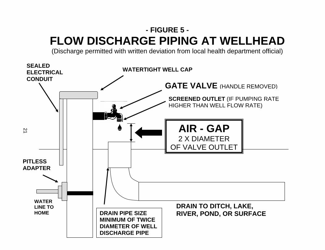
- FIGURE 5 - FLOW DISCHARGE PIPING AT WELLHEAD (Discharge permitted with written deviation from local health department official)
WATERTIGHT WELL CAP
AIR - GAP 2 X DIAMETER
OF VALVE OUTLET
GATE VALVE (HANDLE REMOVED)
DRAIN PIPE SIZE MINIMUM OF TWICE DIAMETER OF WELL DISCHARGE PIPE
SCREENED OUTLET (IF PUMPING RATE HIGHER THAN WELL FLOW RATE)
SEALED ELECTRICAL CONDUIT
WATER LINE TO HOME
PITLESS ADAPTER
21
PRESSURE TANK(DIAPHRAGM OR BLADDER TYPE)
PRESSURE SWITCH
DISCHARGE LINE TO BUILDING
JET OR CENTRIFUGAL PUMP
FLOW RATE CONTROL VALVE
FROM WELL
AIR GAP(PREVENTS CROSS-CONNECTION)
AIR GAP MUST BE AT LEAST TWICE THE DIAMETER OF THE FLOW TANK DISCHARGE LINE
FLOW DRAIN LINE
NONPRESSURIZED STORAGE TANK
DRAIN PIPE MUST BE AT LEAST TWICE THE DIAMETER OF THE TANK DISCHARGE PIPE
PRESSURE RELIEF VALVE
UNION
GATE VALVE
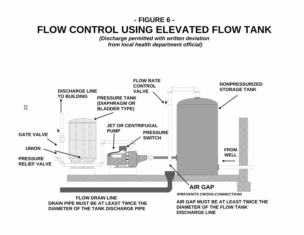
- FIGURE 6 - FLOW CONTROL USING ELEVATED FLOW TANK
(Discharge permitted with written deviation from local health department official)
22

FLOW FROM UNSEALED ANNULUS DIVERTED INTO DRAIN
(SHOULD HAVE BEEN GROUTED TO STOP FLOW)
SURFACE
- FIGURE 7 - UNAPPROVED ANNULAR FLOW
DISCHARGE PIPING
LAKE OR STREAM
WATERTIGHT WELL CAP
GRAVEL POCKETPITLESS ADAPTER
WATER LINE TO HOME
DRAIN PIPE
23

WATER SERVICE
LINE
SURFACE
UNAPPROVED PITLESS ADAPTER CONNECTION (GASKETS OF CLAMP-ON
PITLESS ADAPTERS MUST BE PRESSURIZED
BY PUMP)
CHECK VALVE (DOES NOT PROVIDE
POSITIVE PROTECTION AGAINST BACKSIPHONAGE)
NONPRESSURIZED BURIED LINE (POSSIBLE SUCTION LINE)
WATERTIGHT WELL CAP
CONFINING LAYER NOT SEALED(CORRECTION NEEDED TO SEAL ANNULUS)
UNSEALED ANNULUS
- FIGURE 8 - UNAPPROVED BURIED FLOW
DISCHARGE PIPING WITH CHECK VALVE
24

25
WATER SERVICE
LINE
SURFACE
UNAPPROVED PITLESS ADAPTER CONNECTION (GASKETS OF CLAMP-ON
PITLESS ADAPTERS MUST BE PRESSURIZED
BY PUMP)
NONPRESSURIZED BURIED LINE(POSSIBLE SUCTION LINE)
WATERTIGHT WELL CAP
LAKE OR STREAM
CROSS-CONNECTION WITH SURFACE WATER
(CONTAMINATED SURFACE WATER CAN BE DRAWN INTO WELL THROUGH
SUBMERGED DISCHARGE PIPE)
STATIC WATER LEVEL
PITLESS ADAPTER
- FIGURE 9 - UNAPPROVED BURIED FLOW DISCHARGE
PIPING WITH SUBMERGED INLET
25

26
VENTING OF CASING R 325.1637(1) of the well code requires a casing vent if the pumping rate of the permanent pump exceeds the well flow rate. However, due to problems associated with the snifter valves used to vent flowing wells, the venting requirements are no longer enforced on flowing wells. Snifter valves used on flowing well pitless adapter spools are prone to failure due to hard water encrustation or scaling. Failure of the snifter valve can result in the leakage of water above the spool and above the frost line. Consequently, freezing and damage to the upper casing can occur. Water discharging out of a casing vent or between the casing and the well cap are indicators that the flow control mechanism within the casing is malfunctioning. Problems associated with snifter valve leakage outweigh the benefits of venting. WATER SYSTEM CONFIGURATIONS Persons inspecting water systems with flowing wells can be confused by the wide array of piping/valve/tank/pump arrangements. These systems can have a maze of water service lines and valves that require careful assessment. Inspectors need to be alert for buried flow discharge lines that exit on a brush-filled bank or beneath the surface of a river or lake. Some older flowing well systems use an atmospheric storage tank (or flow tank) to receive the flow (See Figure 6). Flow tanks are acceptable if they are located in an above grade well house. While the well code calls for installing the tanks at an altitude corresponding to the artesian head, the tanks were frequently installed below the artesian head. Atmospheric flow tanks are disapproved under the well code if they are buried. Flow tanks are common in some areas where wells were constructed with an open bottom casing (no screen) and shutting in the well would create cloudy water. Occasionally, the well would continue to produce some sand even though the head was not restricted. Periodically, the flow tank might need draining to get rid of the sand buildup. Systems using a flow tank rely on a shallow-well jet pump and precharged pressure tank to repump the water for pressurized distribution throughout the structure. A float switch or an electronic liquid level control actuates the pump. The water line from the well to the flow tank is pressurized from the constant water head below the point at which the pump shuts off. Flow tanks are recognized as flow control devices, under R 325.1638(2) of the well code, if they meet either of the following conditions:
1. The flow tank is installed at or above the artesian head. 2. The outlet of the flow tank has a discharge rate significantly below
that of the flow tank inlet.
27
WELL CONSTRUCTION METHODS Flowing wells with high artesian head (pressure) and large flow rates are more challenging and troublesome for well drilling contractors. In fact, some well drilling contractors avoid taking drilling jobs in areas where high volume flows are probable. Some drillers prefer to install the pumping equipment for the flowing well after they subcontract the flowing well construction to other well drillers. Insurance companies are now offering policies for Michigan well drilling contractors that specifically cover flowing artesian well breakouts. Deep flowing wells (>200 feet) drilled in glacial drift and flows from bedrock wells are less prone to flow breakout/control problems. Generally, the closer the top of the artesian formation is to the ground surface, the more difficulty in controlling the flow. In known flowing well areas, where artesian pressure at the wellhead is expected to be over 5 psi (11.5 feet of head) or where the flow rate is over 25 gpm, it is highly recommended that well drilling contractors install an outer casing before installing the permanent casing. The outer casing will: (1) maximize chances of controlling flow; (2) contain the flow within a casing if drilling fluid weight is insufficient to overcome the pressure of the flow; and (3) stabilize the soil around the wellhead. The outer casing should be at least 3 to 4 inches larger than the permanent casing, so the permanent casing can be cemented within the outer casing. The outer casing should terminate in the confining layer and should not penetrate the underlying artesian aquifer. Rotary Drilling If rotary drilling methods are used, the outer casing should be grouted into an oversized borehole with neat cement. The cement should be allowed to set before drilling resumes, in accordance with the minimum waiting times listed in R 325.1633a(6) of the Code, before placing the inner permanent casing and drilling into the artesian aquifer. Light flows from shallower formations and heavier flows from deep wells can most often be controlled during rotary drilling operations because of the weight of drilling fluid within the borehole. When water begins flowing from the borehole during rotary drilling operations, a first step should be to increase the drilling mud weight by mixing additional bentonite drilling gel. The artesian flow will dilute the drilling mud and lighten the weight, which increases the upward artesian flow. In some circumstances, the weight of additional drilling gel may be enough to control the flow for the remainder of the hole. However, some drilling gels are beneficiated with polymers to build viscosity and they become difficult to pump
28
before their weight significantly increases. Therefore, some drilling gels have limited ability for control of flows. A typical beneficiated drilling gel may reach only around 8.6 lbs/gal before becoming too thick to pump. Artesian head control is enhanced by using an unaltered, or nonbeneficiated, sodium bentonite drilling gel (meeting American Petroleum Institute Specification 13A), because of the higher hydrostatic pressure that can be applied downhole. Weighting materials, such as powdered barite (barium sulfate - specific gravity of 4.2) are marketed as drilling fluid additives for controlling flows and stabilizing the borehole during drilling. The product manufacturers should be consulted for instructions on use. Cable Tool Drilling If cable tool or other driving methods are used and the thickness of the confining layer is known, a reliable method is to drive an outer casing (with a drive shoe) a few feet into the confining layer, without penetrating completely through the confining layer. The well is completed using a smaller diameter casing telescoped within the outer permanent casing. Granular bentonite is maintained around the outer casing as it is driven. The annular space between an outer casing and an inner permanent casing can be grouted with neat cement or tightly sealed with packers. An advantage to using a telescoped casing installation is that the contractor can avoid the need to bump back the permanent casing to expose the well screen. Bumping the casing back in flowing artesian conditions increases the probability of outer flow breakout. Once the outer casing is driven, it is best not to disturb it and disrupt the seal. An excellent description of the completion of a large volume, high pressure flowing well with cable tool is found in the article written by Brown, 1970. Three separate casing strings (20-, 16-, and 12-inch), with cement grouting of the outer casing, welded steel plates between the casing strings, bentonite drilling mud weighted to 13 lb./gal. with barite, and a drillable plug at the bottom of the 16-inch casing string provided insurance against “wild” flows during well completion. Auger Drilling The use of solid-stem auger drilling is not advised in areas where flowing wells are encountered. Since this drilling method does not take place within a casing and does not employ the use of drilling fluids, the ability of the contractor to keep the borehole under control is limited. Effective grouting of the annular space is less likely to be accomplished using solid-stem augers.
29
INFLATABLE PACKER USE The constant upward flow of an artesian well is an obstacle to the use of slurry-type grouts. Water flow can rapidly dilute the grout unless the grout application rate is higher than the flow rate. Many conventional grouting machines are undersized for handling large flows. In some shallow flowing wells with high artesian heads, the weight of the cement is not high enough to overcome the head and a mechanical seal is needed to stop the flow so it can be cemented. A device that is useful for flowing well work, but not commonly used in Michigan, is the commercially-available inflatable grout packer. The packer is set just out of the end of the casing, on a pipe string within the casing. A mechanical seal is created between the casing and borehole when the packer is inflated with compressed air. Once the flow is stopped or significantly reduced, grout is placed through a grout pipe(s) above shale traps (also called formation packers) located just above the inflatable packer. After the grout sets, the packer is deflated and removed through the interior of the well casing. GROUTING MATERIALS Cement-based grouts, such as neat cement, are recommended for flowing well construction or repair. The solids content, density, specific gravity, and strength of cement grouts make them more suitable for artesian well applications than bentonite grouts. The heavier slurry density of cement-based grout results in higher downhole pressure within the borehole. Therefore, cement grouts overcome artesian head conditions more readily than lighter bentonite slurry grouts. Accelerators, such as calcium chloride, and lost circulation materials, such as cellophane flake, are useful cement additives in some situations. Cement grout slurries that are heavier than typical neat cement slurries can be designed by using special additives called friction reducers. Friction reducers allow the cement to be hydrated with less water. The lower water to cement ratio results in an increase in the downhole pressure exerted by the grout. Table 1 shows densities and hydrostatic pressures of water well grouts.

30
Table 1 Hydrostatic Pressure of Common Grouts
Hydrostatic
Material Density (lbs./gal.) pressure (psi/ft.)
Thixotropic cement (4 gal water/sack*) 16.5 0.85 Neat cement (5.2 gal. water/sack) 15.6 0.81 Neat cement (6.0 gal. water/sack) 15.0 0.78 Bentonite grout (30% solids) 10.4 0.54 Bentonite grout (20% solids) 9.5 0.49 Granular bentonite/polymer slurry (15% solids) 9.2 0.48 Bentonite drilling fluid (38 sec. viscosity) 9.0 0.47 Water 8.3 0.43
* with cement friction reducer/fluid loss additive Neat cement slurry with calcium chloride accelerator has been successfully used for sealing annular flows. The faster set of the cement helps control the flow by reducing the amount of time during which the cement is subject to dilution. However, accelerated cement cannot be applied with the typical intermittent batch pumping scheme commonly used by Michigan well drillers for grouting of new wells. Because of the faster set of the cement, it is necessary to mix a single batch that must be pumped without interruption. If small batches are intermittently applied, the initial batches can be setting downhole and may prevent pumping of the full amount of cement needed to seal the flow. Caution and diligence are necessary when accelerated cement is used. Common flake-type calcium chloride can be used, but the concentration should never exceed 5 percent by weight of cement. Higher levels can flash set in the pump and hoses. The following mixing procedure for 3 percent calcium chloride is suggested:
1. Mix 5 gallons of fresh cold water for each 94 lb. sack of Portland Type IA cement until the entire batch is free of lumps.
2. Fill a separate mixing container with one gallon of water for each sack of cement used in step #1.
31
3. Add calcium chloride to the water at a rate of 2.8 lbs for each sack of cement in step #1. Thoroughly mix the solution until the calcium chloride is dissolved.
4. Add the water/calcium chloride solution to the cement/water slurry and promptly mix thoroughly.
5. Pump the cement/calcium chloride slurry down the casing or through the grout pipe(s) without delay. The pumping rate should be high enough to ensure that the entire batch is pumped downhole within 5 minutes.
The American Society for Testing and Materials (ASTM) D 5299-92 well plugging standard notes that sodium chloride can also be used as a cement accelerator. ASTM recommends from 1.5 to 5 percent by weight of cement and points out that maximum acceleration of the cement set occurs at 2 to 2.5 percent, except when higher water ratios are used. The advantages and disadvantages of specific well grouting materials is a subject of debate within the water well industry. Researchers at Colorado State University, Department of Civil Engineering, published the results of studies that indicate the limitations of bentonite grout performance in confined (artesian) aquifers. Ogden and Ruff (1991, 1993) point out that the shear strength of annular seals is important to resist hydrostatic push-out forces in confined aquifers. They conclude that bentonite slurry grouts have little ability to resist the axial forces that can displace the grout seal in confined geologic settings. Ogden and Ruff (1991) state: “The low shear strength of bentonite grouts makes them unsuitable for high hydraulic gradient sealing locations where strength is important.” Their 1993 report advises that “bentonite slurry grouts should never be applied in confined aquifer boundaries without additional mechanical support such as packers or adjacent cementitious seals, unless the aquitard thickness is at least two-thirds of the expected maximum drawdown.” Michigan water well regulatory officials have observed numerous failures of bentonite annular seals around flowing wells. The studies conducted by Ogden and Ruff (1991, 1993) may help identify the mechanisms of the failures. The main factors that impact the efficacy of bentonite seals in artesian settings are the shear strength, critical hydraulic gradient, setting time, and annular space dimensions. Bentonite seals can fail due to piping, shear, or a combination of both. “Piping” is the washing or erosion of the bentonite clay particles caused by the flow of water. As the bentonite platelets swell downhole, the resulting seal can have an inhomogeneous structure with variable solids content. Areas within the seal with lower solids content will have a lower critical hydraulic gradient and will be more

32
prone to failure. If the lower solids areas are interconnected, a preferential flow path is created. When the upward hydrostatic force of the artesian water exceeds the critical hydraulic gradient across the axial surface of the seal, the flow can rupture the grout seal and water can find its way to the ground surface. Shear failure occurs if the hydrostatic force overcomes the cohesion forces between the grout and the borehole and between the grout and the casing, which results in movement of the seal. The structural integrity of the seal can be impacted by grout setting time and casing/borehole dimensions. Ogden and Ruff (1991) noted that smaller annular seal thicknesses (higher casing-to-borehole diameter ratio) result in more spatial variability of the solids content of the grout. The smaller the thickness of the annular seal, the more susceptible the seal is to piping. Their studies also showed that the shear strengths of bentonite grouts increase with time. Bentonite chips were found to develop 50 percent of the maximum observed shear strength within 10 to 20 hours and the ultimate strength was not reached until 72 to 120 hours after placement. During flowing well grouting, it is important that the structural strength of the grout be available immediately upon placement. Field experience has shown that once the flow has broken through a bentonite seal, additional swelling of the bentonite that may occur after placement does not seal off the flow. ARTESIAN HEAD CONSIDERATIONS Understanding pressure conditions within flowing wells is important when constructing flowing wells or dealing with discharge control issues. When working with hydraulic pressures, such as artesian head and downhole hydrostatic head pressure (DHHP), the following formula is used to convert from feet of water to pounds per square inch of pressure:
2.31 feet equals 1 psi
This formula means that a column of water 2.31 feet in height produces pressure at the bottom of the column of 1 psi. The relationship between feet of head and pressure is influenced by the fluid weight. As the fluid weight increases, the resulting pressure increases. Another useful formula for water is:
0.433 psi equals 1 foot
This formula can be explained by distributing the weight of water over the bottom surface area. A gallon of water weighs 8.34 lbs. A cubic foot of water contains 7.48 gallons. The weight of a cubic foot of water is 62.4 lbs, based on 8.34 lbs/gal

33
X 7.48 gal/cu. ft. If the cubic foot weight (62.4 lbs) is divided by the area of the bottom of the cube (one square foot, or 12 inches per side, equals 144 square inches), the result is 0.433 psi. Note the conversion of a fluid density to a pressure can be accomplished by multiplying the fluid weight in lbs/gal by 0.052. The empirical multiplication factor of 0.052, which is used in later calculations in this handbook, converts lbs/gal into psi/ft of depth. Some important definitions to remember are:
“Piezometric level” - the level to which water in a confined aquifer will rise within a well. It is the same as the static water level, except that in a flowing well, the piezometric level is above the ground surface. It is not possible to look at the volume of an artesian well discharge and tell where the piezometric level is at. The piezometric level is expressed in feet above ground surface. “Artesian head” – the hydraulic pressure created within the confined aquifer that drives the water upward in a well to the piezometric level. The distance from the ground surface to the piezometric level, converted into equivalent pressure (expressed as pounds per square inch, or PSI), is the artesian head. “Downhole hydrostatic head pressure” (or DHHP) is the hydrostatic pressure at the top of the artesian aquifer, which results from the combination of the artesian head and a water column extending from the top of the artesian aquifer to the ground surface. “Downward grout pressure” (or DGP) is the pressure that must be exerted by the grout in order to equalize the DHHP. Determine the DGP by multiplying the grout weight (or density) by 0.052, then multiplying by the depth to the top of the artesian aquifer (0.052 is a short-cut conversion explained above). Therefore, DGP is expressed as: Grout weight (lbs/gal) X 0.052 X depth to top of artesian aquifer (ft)
Measuring Artesian Head Finding the piezometric level and artesian head can be done using either of the following means:
1. Extend the well casing, or a smaller diameter pipe through a well seal on the top of the casing, high enough above the ground surface until water no longer flows out the top (without pumping), The distance from the piezometric level within the casing, to the ground surface, converted from

34
feet to pressure, is the artesian head of the aquifer. For example, a piezometric level of 30 feet is converted to artesian head by dividing 30 feet by 2.31 feet/psi. The result is 13 psi of artesian head.
2. A pressure gauge installed on a well seal at the top of the casing can be used
to find the piezometric level and artesian head. Multiply the pressure reading on the gauge (in PSI) by 2.31 feet to find the piezometric level. The pressure gauge reading is the artesian head at the gauge elevation. Example: If the gauge records 10 psi of pressure, the piezometric level caused by the artesian head is 10 psi X 2.31 feet per psi, or 23.1 feet. Therefore, the artesian head would push the water 23 feet above the top of the casing (to the piezometric level). If the casing is 1 foot above surface, the piezometric level is 24 feet.
Downhole Hydrostatic Head Pressure The chart in Appendix A, Downhole Hydrostatic Head Pressure for Flowing Artesian Wells, is useful for finding the DHHP and for understanding the relationship between drilling fluid or grout density and their ability to successfully control the flow during drilling, plugging, or repair. The chart clearly shows that heavy grouts, such as neat cement slurry or cement slurry with additives, have a distinct advantage for flowing well work. Because cement-based grouts have a significantly higher density than bentonite grout, more DGP is exerted within the borehole. To successfully overcome the flow, the DGP must exceed the DHHP. The weight difference between the grout and water (8.34 lbs./gal.), must outweigh the pressure of the artesian head. The Flowing Well Worksheet in Appendix E has example problems that illustrate these principles. FLOW AROUND CASING Under R 325.1638(1) of the well code, the flow must be confined to within the casing. If water begins flowing from the borehole or up the annulus surrounding the casing before well construction is completed, the contractor should immediately take steps to confine and control the flow. If a flow breaks out along the casing of an existing well, the property owner should be made aware of his or her legal responsibility to correct the problem and a water well drilling contractor should be immediately consulted. While all breakouts need attention, a breakout where turbid water flows from the annulus is potentially more hazardous and needs immediate attention.

35
Water flowing around the casing at the surface may not be originating from the same aquifer into which the casing is terminated. An upper geologic stratum containing artesian water may have been bypassed during the well construction process. The flow may have been held back temporarily by the drilling fluid or shut off as casing was driven through it. A review of the driller’s log can help identify the locations of permeable zones that are likely sources for the annular flow. One method commonly used to assess whether the annular flow is hydraulically connected to the flow on the inside of the casing is to pump the inner flow until the water level drops below the ground surface. If the annular flow responds identically to the pumping by falling below ground, the flows are coming from the same aquifer. If the outer flow is unaffected while pumping from the well, the flow is originating from an overlying permeable zone. While this method is useful for establishing whether hydraulic interconnection exists between the outer and inner flow, it does not suggest the route of the flow. A damaged well casing or defective casing joint near the surface can cause water to flow along the casing up to the surface. Leaking water lines that are buried near a flowing well can sometimes appear to be originating from the annulus. Analyzing the chemical quality of the water leaking around the casing and comparing it to the quality of the water within the casing can also help identify the source of the outer flow. If the levels of hardness, iron, chloride, sulfate, conductivity, and other chemical parameters from the two well locations (outside casing and inside casing) are significantly different, the annular flow is likely to be from an aquifer that is hydraulically disconnected from the casing flow. ANNULAR FLOW CORRECTION PROCEDURES Stopping the annular flow (outside the permanent casing) is less difficult if the flow can be contained within an outer casing. The outer casing can be extended above the piezometric level before placement of the grout. For minor breakouts, outer casing installation may not be needed. Correction of annular flows may include any of the following methods, or a combination of methods:
1. Place a grout pipe (also called a “tremie pipe”) into the annulus, extend the grout pipe(s) into a confining layer, and pump neat cement or a cement/accelerator admixture. Several grout pipes can be joined together with a manifold so that cement can be simultaneously pumped down the grout pipes. If the flow is suspected to originate from several zones, the grout pipes can terminate at different depths. For high head flows, it is preferable to leave the grout pipes in place rather than extracting them from the borehole after cementing. Quick-connect couplings placed on top

36
of the grout pipes will speed up the operation. A check valve placed beneath the quick-connect coupling will prevent artesian pressure from pushing cement out of the grout pipes after the grout hoses are disconnected. Grouting materials should be pumped into the annulus (down grout pipe[s]), or through the casing, with positive displacement pumping equipment, and should be placed as close to the source of the flow as possible. If the flow has not been contained within a casing extending upward to a point above the artesian head, the grout must be pumped at a rate that exceeds the artesian flow rate. A key objective is to overwhelm the annular space and/or borehole with the heavier fluid to overcome the flow. If the grout is pumped at a rate that is lower than the well’s flow rate, the flow can dilute the grout and wash it out of the borehole. A batch of grout at least twice the borehole volume should be prepared and quickly pumped.
2. Install a casing adapter on the top of the well casing and pump cement grout directly through the well casing. If the inner and outer flows are hydraulically connected, the grout will exit the bottom of the casing and be carried upward into the annulus by the artesian flow. While this method is highly successful, a disadvantage is that the inside of the well casing is cemented in the process. It is important that the cement remain pressurized above the formation pressure until initial set of the cement has occurred.
3. Drive a larger diameter pipe around the casing and extend the outer casing
into a confining layer. Additional collars added to the pipe can improve the chances of successfully sealing the borehole. Once the casing is seated and the flow is contained within the larger pipe, the formation materials between the two pipes can be jetted out and the void space grouted. For high head flows, or where the top of the artesian aquifer is close to surface, the outer casing can be extended above the surface to act as a standpipe to provide more cement weight. After cementing, the outer casing and hardened cement column are removed.
Stopping the annular flow may kill the entire well, since sealing material can migrate around the end of the casing into the casing interior. Correcting an annular flow is simpler if the flow can be drawn down below ground by over pumping. A large capacity pump can be temporarily installed to dewater the annulus so that cement can be placed with less chance for washout of the cement before the set-time is reached.

37
Fortunately, well drillers are usually able to complete flowing wells without any complications. However, when a large volume, high pressure flow breaks out, the drilling crew can overreact and a “panic mode” may ensue. There is usually an overriding concern to quickly move the drilling rig away from the borehole, in case subsurface washouts or collapse craters are forming. Hastily made decisions on how to seal the casing can impede the success of future corrective actions.
Some field practices to avoid are:
1. Dumping field stone or gravel into the annulus - The stone or gravel can prevent the installation of grout pipes or larger casing into the borehole and can collapse PVC well casing. Smith (1994) suggests pouring gravel to add friction to slow the flow. However, field experiences in Michigan have shown that if the gravel does not sufficiently slow down the flow, the presence of the gravel in the well bore or annulus hinders further corrective action. Also, in high head/high volume flowing wells, the upward flow can have enough energy to keep the stones or gravel from reaching the bottom of the borehole or annulus.
2. Pouring ready-mixed concrete or bentonite chips into the annulus –
Penetration of the concrete or bentonite to the depth at which the flow originates is unlikely. The result can be a hardened surface plug and the flow can wash out around the perimeter of the plug. The concrete components can separate within the annulus or borehole, with the lighter cement portion being washed out of the hole and the heavier aggregate bridging downhole above the flow. The weight and heat of hydration from a massive block of concrete surrounding a PVC plastic casing can complicate future correction. If the flow breaks out at the perimeter of the concrete plug, further correction (such as installing grout pipes into the annulus) would require that the concrete plug be broken up and removed.
3. Stopping the driving of an outer casing before a solid confining layer is
reached - If the outer casing does not extend far enough, flow from the artesian formation can continue to leak into an upper formation.
4. Jamming unopened bags of cement, bentonite chips, lumber, cardboard,
or other debris into the washed out annulus – These materials are ineffective and complicate further corrective action.

38
DISINFECTION OF FLOWING WELLS From a geologic standpoint, flowing wells appear less prone to coliform bacteriological contamination problems. The protected nature of the confined artesian aquifers, through positive upward pressure in the aquifer pore space, should minimize the migration of coliform organisms into the aquifer. Smith (1994) notes that while a flowing artesian well is sometimes a practical nuisance, the positive artesian head can help keep surficial contamination out of the aquifer. Eradicating a bacterial contamination problem in a flowing well can be challenging. Bacteriological contamination introduced during the drilling process may be flushed out by the continuous discharge of water. However, remaining contaminants can be difficult to inactivate with chlorine disinfectant unless the flow is stopped. Adequate contact with the disinfectant cannot be attained if the well is continually flowing. To disinfect a flowing well, some contractors will install a temporary casing extension (standpipe) that reaches the piezometric level or they will install a tight well cap or seal to stop the flow in order to achieve the needed chlorine contact period. Afterward, the casing extension or cap is removed and the well discharge flushes the residual chlorine and inactivated bacteria from the well. FLOW DISCHARGE PIPING AND CROSS CONNECTION HAZARDS If water from a new flowing well is allowed to discharge from the casing (pursuant to the well code) cross connection piping hazards must be avoided when installing the discharge piping. A cross connection is a piping arrangement that can allow nonpotable water or sewage to enter the water system as a result of backflow or backsiphonage. Cases have occurred in Michigan where the water system became bacteriologically contaminated after the pump lowered the water level within the well and surface water entered the submerged discharge pipe from a flowing well. Buried drain lines that carry annular flows to surface waters (See Figure 7 and 9) can pose a threat to the aquifer if the discharge outlet is submerged. R 325.1638(2) of the well code prohibits a discharge pipe from a flowing well to be directly connected to a sewer or other source of contamination. A recommended method to discharge the casing flow without a cross connection hazard is to air-gap the overflow pipe at the wellhead, before discharging the water into a sewer or drain pipe. (See Figure 5.) The well discharge or overflow line must connect to the well casing at least 12 inches above ground surface. The size of the gap of air between the overflow pipe from the well and the sewer line into which the overflow discharges, should be at least twice the diameter of the well overflow pipe. This assures that if a backflow condition occurred within the water system, the vacuum would be broken as air entered through the overflow pipe. The air-gap must be

39
installed at the wellhead rather than at the end of the discharge piping. A check valve cannot be substituted for an air-gap because hard water scaling or sediment particles can cause failure of the check valve. The drain pipe that receives the discharge from the well overflow pipe should be at least twice the diameter of the overflow pipe. Overflow water must be diverted to prevent ponding around the well casing. Another related hazard occasionally found on existing flowing well systems is burial of the flow discharge pipe. An example of such an unapproved arrangement is where a connection has been made to the well casing below the water service line connection. Sometimes the buried discharge line terminates at ground surface or it may have been submerged into a surface water body. A buried water line that is not under positive pressure at all times is a potential health hazard because contaminants can be drawn in through faulty joints or holes caused by corrosion. While the well is flowing the artesian head provides slight pressurization of the pipe. But if the water level is lowered within the well due to pumping or natural artesian head fluctuations, the flow within the discharge pipe will stop and the pipe is no longer pressurized. Installing the air-gapped overflow described above at the wellhead eliminates concern over burial of the overflow drain pipe downstream from the well. Clamp-on pitless adapters on buried flow discharge lines pose another hazard. The unapproved buried discharge pipe described above is sometimes connected to the well casing using a clamp-on pitless adapter. Clamp-on pitless adapters are approved under the well code only if the gaskets on both sides of the casing remain under positive pressure at all times. If the gaskets do not remain pressurized, contaminants can be drawn into the water system through the gaskets if the water level in the casing drops below the pitless adapter during pumping. This can occur whenever the pumping rate exceeds the well’s flow rate. The only instances where a buried discharge line with a buried clamp-on pitless adapter should be permitted is: (1) where the well was installed before February 14, 1967(effective date of the first well code); and (2) the artesian head measured at the wellhead is 10 psi or greater and the flow rate of the well exceeds the pumping rate of the pump. PLUGGING ABANDONED FLOWING WELLS Plugging of an abandoned flowing well requires special practices. Under R 325.1663(3) of the well code, a flowing well must be plugged with neat cement or concrete grout. Special admixtures and materials can be accepted on a case-by-case basis, with approval of the health officer of the local health department.

40
If the abandoned flowing well has a leaking annulus, the methods described in the “Annular Flow Correction Methods” section of this handbook are recommended. The annulus should be sealed before proceeding with plugging the interior of the casing. Once the flow control device (such as a flowing well spool pitless unit or stacked drawdown seals) is removed the well will begin flowing onto the ground surface. Unless the flow is properly diverted, the work site can become treacherous. The well plugging contractor should be prepared to handle the flow and the discharge of any plugging materials immediately upon removal of the flow control device(s). Plugging an abandoned flowing well located within a basement (or other below grade structure, such as a well pit) requires special care. During remodeling of an office building in Oakland County in 2000, a 6-inch artesian well was discovered within an interior wall that was being demolished. The artesian head of the well was a few inches above the paved parking lot. To plug the well, the contractor installed a temporary sump and pumped the well discharge out of the building. The well was successfully sealed with neat cement. Abandoned well plugging is simplified if the artesian pressure can be overcome by extending the well casing above the piezometric level. If the artesian head is high, a hydraulic lift or crane can be used to place the grout pipe within the extended casing. Another alternative is to physically stop the flow by placing an inflatable packer, expandable rubber plug, or cedar plug near the bottom of the casing. Once the flow is stopped within the casing, the grout is placed without fear of washout. Erecting a building over a plugged abandoned flowing well is risky and is not advised. The structural integrity of the annular seal of an older flowing well is often uncertain. If the inside of the casing is sealed with cement, the flow can breakout afterward. Once a structure is built over the well, correction to seal a breakout is difficult and costly. A major breakout could threaten the stability of the structure. A case that occurred in Plymouth, Wayne County, points out the need to accurately record the location of plugged abandoned wells and to make owners, developers, and excavation contractors aware of the well location. A 6-inch steel cased well was plugged in 1988 with cement from the bottom to top of the casing. In 1993, an excavator who was preparing the site for an underground storage tank (UST) installation broke off the upper portion of the well casing. The contractor pushed the casing back into the hole, proceeded to pour a cement pad over the well and completed the UST installation. A hydrogeological consultant later recorded

41
mounding of ground water in the vicinity of the abandoned well, which was likely due to leakage from the disturbed well. An article in the Water Well Journal in 1995 illustrates an effective, but costly, approach for plugging a flowing well by lowering the water level by pumping from adjacent wells. In order to plug a 400 gpm flow from a 6-inch well that was not constructed to handle a flowing condition, two additional wells were drilled. After the second well (8-inch casing) was completed, it flowed 400+ gpm, but water could not be pumped out fast enough to lower the water in the initial well. A third well, (with 12-inch casing) flowed at 800 gpm and was pumped at 4000 gpm to lower the water enough so that the first well casing could be pulled and the hole cemented. Pumping continued for 24 hours until the cement set and afterward, the second and third wells were capped. LOCAL HEALTH DEPARTMENT WELL PERMITS FOR FLOWING WELL AREAS Local health department (LHD) well permit programs should include a mechanism for delineating areas where flowing wells occur. A reference for obtaining data on flowing well locations within Michigan is Allen, (1974). The Wellogic water well records data base and the scanned water well record database provided by the MDEQ are useful for finding flowing well areas. When a well is proposed to be drilled in an area where flowing wells are known to occur, the permit issued by the LHD should advise the homeowner and the well drilling contractor of the possibility of encountering flowing well conditions. In known flowing well areas, property owners are advised against attempting to drill their own wells. Property owners are ill-equipped to correctly handle the situation if a breakout occurs, nor are they familiar with the devices needed to control the flow within the casing. They should be strongly advised to hire a registered water well drilling contractor to construct the well. OTHER PERMITS If a new artesian well discharges water into a wetland or surface water body, additional permits may be needed. The Michigan Natural Resources and Environmental Protection Act (NREPA)(1994, PA 451) Part 91 (Soil Erosion and Sedimentation Control), Part 301 (Inland Lakes and Streams), and Part 303 (Wetland Protection), may be applicable depending on the specific circumstances of the discharge. The construction of a spillway or buried drain line within a wetland or the discharge of the water below the water level of a lake, are examples of situations that would typically need permits under NREPA. The local soil erosion/zoning officer should be contacted to find out if a permit is needed.
42
References
1. W. B. Allen, Flowing Wells in Michigan, 1974 U. S. Geological Survey, Water Information Series Report 2
2. ASTM D 5299-92, Standard for Decommissioning of Ground Water
Wells, Vadose Zone Monitoring Devices, Boreholes, and Other Devices for Environmental Activities, 1993, American Society for Testing Materials, West Conshohocken, Pennsylvania.
3. Bernard v. City of St. Louis, 220 Mich 159, 189 NW2d 891 (1922). 4. W. L. Brown, Largest Flowing Well In Canada at Fort St. James, Johnson
Drillers Journal, March-April 1970, UOP Johnson Division, St. Paul, Minnesota.
5. Stanley N. Davis,. and Roger J. M. DeWiest, Hydrogeology, 1966, John Wiley
& Sons, New York. 6. Fletcher G. Driscoll, Groundwater and Wells, 1986, Johnson Division,
St. Paul. Minnesota. 7. Environmental Health Ready Reference, 1990, Michigan Environmental
Health Association, 8. C. W. Fetter, Applied Hydrogeology, Second Edition, 1988, Merrill Publishing
Co., Columbus, Ohio 9. R. Allen Freeze, and John Cherry, Groundwater, 1979, Prentice Hall, Inc.,
Englewood Cliffs, New Jersey 10. Michael S. Gaber, and Brant O. Fisher, Michigan Water Well Grouting
Manual, 1988, Michigan Department of Public Health, Lansing, Michigan. 11. Group Stops Flow of Artesian Well, Water Well Journal, December 1995,
Ground Water Publishing Co., Dublin, Ohio. 13. Halliburton Cementing Tables, 1981, Halliburton Services, Duncan,
Oklahoma.
43
14. Frank Leverett, et al., Flowing Wells and Municipal Water Supplies in the Southern Portion of the Southern Peninsula of Michigan, 1906, U.S. Geological Survey , Water Supply and Irrigation Paper No. 182, Government Printing Office, Washington.
15. Frank Leverett, et al., Flowing Wells and Municipal Water Supplies in the
Middle and Northern Portions of the Southern Peninsula of Michigan, 1907, U.S. Geological Survey, Water Supply and Irrigation Paper No. 183, Government Printing Office, Washington.
16. Oscar E. Meinzner, Compressibility and Elasticity of Artesian Aquifers,
(Econ. Geology 1928), Reprinted in Historical Perspectives, Ground Water, Vol. 24, No. 3, May-June 1986 and Vol. 24, No. 4, July-August 1986, Water Well Journal Publishing Co., Columbus, Ohio
17. Minnesota Department of Health, The Control of Flowing Wells, Ground
Water Age, May 1989, National Trade Publications, Latham, NY 18. Fred L. Ogden, and James F. Ruff, Setting Time Effects on Bentonite
Water-Well Annulus Seals, Journal of Irrigation and Drainage Engineering, Vol. 117, No. 4, July/August 1991.
19. Fred L. Ogden, and James F. Ruff, Strength of Bentonite Water-Well
Annulus Seals in Confined Aquifers, Journal of Irrigation and Drainage Engineering, Vol. 119, No. 2, March 1993.
20. Tom Riewe, Why Do Some Wells Flow?, Water Well Journal, June 1992,
Ground Water Publishing Co., Dublin, Ohio. 21. Schenk v. City of Ann Arbor, 196 Mich 75, 163 NW 109 (1917). 22. Stuart A. Smith, Well & Borehole Sealing: Importance, Materials,
Methods, and Recommendations for Decommissioning, 1994, Ground Water Publishing Co., Dublin, Ohio.
23. Gloria J. Swanson, Super Well is Deep in the Heart of Texas, Water Well
Journal, July 1991, Ground water Publishing Co., Dublin, Ohio.

44
Appendix A Downhole Hydrostatic Head Pressures (PSI) for Flowing Artesian Wells
Depth to Top of
Flowing Aquifer (feet) Artesian Head Above Ground Surface
(feet) 5 10 15 20 25 30
10
6.5
8.7
10.8
13.0
15.2
17.3
20
10.8
13.0
15.2
17.3
19.5
21.7
30
15.2
17.3
19.5
21.7
23.8
26.0
40
19.5
21.6
23.8
26.0
28.1
30.3
50
23.8
26.0
28.1
30.3
32.5
34.6
75
34.6
36.8
39.0
41.1
43.3
45.5
100
45.5
47.6
50.0
52.0
54.1
56.3
125
56.3
58.4
60.6
62.8
65.0
67.1
150
67.1
69.3
71.4
73.6
75.8
78.0
175
78.0
80.1
82.3
84.4
86.6
88.7
200
88.7
91.0
93.1
95.2
97.4
99.6
225
99.6
101.7
104.0
106.0
108.2
110.4
250
110.4
112.5
115.7
117.0
119.0
121.2 Material Weight Hydrostatic Pressure Neat Cement @ 6 gal water/sack: 15.0 lb/gal .78 psi/ft Bentonite Slurry Grout: 10.4 lb/gal .54 psi/ft Bentonite Slurry Grout: 9.5 lb/gal .49 psi/ft
GROUTING MATERIAL SUITABILITY
HEAVY ENOUGH TO OVERCOME NOT HEAVY ENOUGH TO OVERCOME HYDROSTATIC PRESSURE HYDROSTATIC PRESSURE Neat Cement w/weight additives Neat Cement @ 15 lb/gal and all Bentonite Grouts Neat Cement @ 15 lb/gal All Bentonite Grouts Neat Cement @ 15 lb/gal or Bentonite Grouts lighter than Bentonite Grout @ 10.4 lb/gal 10.4 lb/gal
All standard grouts have enough weight to overcome hydrostatic pressure of the flow.

45
APPENDIX B
FLOW RATES The tables below are useful in estimating flow rates from flowing wells or pump discharges. VERTICAL PIPE – The approximate flow rate from a vertical pipe can be
determined by measuring the height (H) that the water rises above the top of the pipe and the inside diameter (D) of the pipe. Find the flow rates for various H and D values in the table below.
FLOW IN GPM FROM VERTICAL PIPES
INSIDE PIPE DIAMETER (D) IN INCHES HEIGHT (H) IN INCHES 1¼ 2 3 4 5 6 8 10
2 11 28 63 112 175 251 447 698
3 13 35 77 135 217 311 569 950
4 15 41 92 161 252 369 687 1115
6 19 52 115 202 316 469 872 1415
8 22 61 135 236 370 548 1025 1640
10 24 69 153 265 418 621 1155 1840
12 27 76 169 294 463 685 1275 2010
14 29 83 184 319 502 740 1380 2170
16 31 89 197 342 540 796 1480 2320
18 33 95 209 364 575 845 1560 2460

46
HORIZONTAL PIPE – The approximate flow rate from a horizontal pipe can be determined using an L-shaped measuring square and finding the horizontal distance (A) in inches. This measurement will represent the distance between the end of the pipe and the point that the 4 inch end of the square touches the water. D represents the inside diameter of the pipe. Find the flow rate for various A and D values in the table below.
FLOW IN GPM FROM HORIZONTAL PIPES INSIDE PIPE DIAMETER (D) IN INCHES HORIZONTAL
DISTANCE (D) IN INCHES
1¼
2
3
4
5
6
8
10
4 10 22 48 83 - - - - 6 15 33 73 125 195 285 - - 8 20 44 97 166 260 380 665 1060 10 24 55 122 208 326 476 830 1330 12 29 66 146 250 390 570 1000 1600 14 34 77 170 292 456 670 1160 1860 16 39 88 196 334 520 760 1330 2120 18 - 99 220 375 590 860 1500 2390
(From Environmental Health Ready Reference, Michigan Environmental Health Association, 1990)

47
APPENDIX C
Flowing Well Discharge Deviation
This is to allow for a deviation of the provisions of R 325.1638 of the Michigan Well Construction and Pump Installation Code (Part 127, 1978 PA 368). This deviation is authorized under R 325.1613. Well owner Home phone
Address Work phone
City State Zip code
Well site address
Well permit application date Well permit number
Unrestricted flow rate gpm Proposed discharge rate gpm
Reason(s) for deviation:
Control of flow not practical – Give reason(s) Flow control will result in sand/turbidity production. Discharge is for beneficial use: Maintain water level in pond Fire protection Industrial process Heating/cooling Irrigation Other
Person requesting deviation Date Local health department official Date Department

48
Appendix D
Flowing Well Damages Act Act 236, Public Acts of 1961, effective January 1, 1961 (initially Act 107, session of 1905)
MCL 600.2941 Artesian or flowing well; certain condition deemed nuisance, abatement, damages. (M.S.A. 27A.2941)
Sec. 2941. (1) Any artesian or flowing well, the water of which is unnecessarily allowed to run to waste in an unreasonable manner to the depletion or lowering of the head or reservoir thereof to the detriment or damage of other wells supplied from the same head or reservoir, is a nuisance, and its owner and the owner of the land on which it is situated are subject to all the actions for abatement and damages in favor of the person or persons injured, as provided by law for other nuisances or tortious acts.
Wells, unreasonable or unnecessary waste; abatement, damages.
(2) Where any well is supplied by a head, reservoir, stratum, or vein or by percolating waters common to other springs or wells, and the owner thereof or his lessee or licensee puts its waters to a use unreasonable or unnecessary, in view of the condition and situation of the land on which it is situated, and through such unreasonable or unnecessary use, lowers or depletes the head, pressure, or supply of water of any spring or well dependent on the same head, vein, or stratum, to the detriment or injury of the owner or any person entitled to the use thereof, the well so unreasonably or unnecessarily used, is a nuisance, and its owner and the owner of the land on which it is situated are subject to all the actions for abatement and damages in favor of the person or persons injured, as provided by law for other nuisances or tortious acts.
Judgments, contents, reopening. (3) Where any order or judgment is rendered under this section, declaring any well a nuisance because of the waste or unreasonable use of its waters and directing the abatement thereof, such order or judgment shall specify in some practical manner the daily amount or volume of water that may be used or allowed to flow therefrom without violating such order or judgment, and specify such reasonable time as to the court shall seem just within which the provisions thereof shall be carried into effect. Any such order or judgment may be reopened at any time after entry on the question of reasonable use on a proper showing of change of circumstances or other equitable reason therefor.
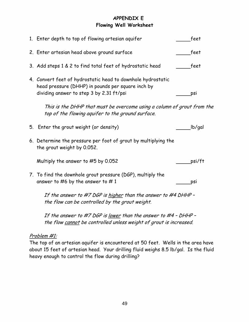
49
APPENDIX E Flowing Well Worksheet
1. Enter depth to top of flowing artesian aquifer feet 2. Enter artesian head above ground surface feet 3. Add steps 1 & 2 to find total feet of hydrostatic head feet 4. Convert feet of hydrostatic head to downhole hydrostatic
head pressure (DHHP) in pounds per square inch by dividing answer to step 3 by 2.31 ft/psi psi
This is the DHHP that must be overcome using a column of grout from the top of the flowing aquifer to the ground surface.
5. Enter the grout weight (or density) lb/gal 6. Determine the pressure per foot of grout by multiplying the
the grout weight by 0.052. Multiply the answer to #5 by 0.052 psi/ft
7. To find the downhole grout pressure (DGP), multiply the
answer to #6 by the answer to # 1 psi
If the answer to #7 DGP is higher than the answer to #4 DHHP – the flow can be controlled by the grout weight. If the answer to #7 DGP is lower than the answer to #4 – DHHP – the flow cannot be controlled unless weight of grout is increased.
Problem #1: The top of an artesian aquifer is encountered at 50 feet. Wells in the area have about 15 feet of artesian head. Your drilling fluid weighs 8.5 lb/gal. Is the fluid heavy enough to control the flow during drilling?

50
Solution #1: The DHHP for the well is 65 feet (50 feet + 15 feet) divided by 2.31 ft/psi, or 28 psi. To find the DGP, use the formula:
drilling fluid (or grout weight) X 0.052 X depth to top of artesian aquifer 8.5 lb/gal X .052 X 50 = 22 psi. Since the downward pressure of the drilling fluid (22 psi) is less than the DHHP of the well (28 psi), the fluid is too light to control the flow. Problem #2: The DHHP for a deep well was calculated using steps 1 through 4 above and found to be 150 psi (based on a depth of 300 feet to the top of the artesian formation and an artesian head of 20 psi). What minimum weight drilling fluid would be needed to overcome the DHHP during drilling? Solution #2: Use the following steps to solve this problem:
Step A.: Convert the artesian head to feet; then divide the feet by the depth to the top of the artesian aquifer to find the downward pressure, above the weight of water, which is required for each foot of grout column height:
20 psi X 2.31 ft/psi = 46 feet
46 feet divided by 300 feet = 0.15 psi /ft.
Step B: Add 0.15 psi/ft to the hydrostatic pressure caused by 1 foot of water to find the downward pressure of the grout:
0.15 psi/ft + 0.433 psi/ft = 0.583 psi/ft
Step C: Divide the downward pressure of the grout by 0.052 to find the
weight (density) of the grout:
0.583 psi/ft divided by 0.052 = 11.2 lb/gal.
This is the weight of the grout that will equalize the DHHP.

51
Problem #3 The top of an artesian aquifer is encountered at 100 feet. Wells in the area have about 30 feet of head. You plan to grout the casing with neat cement grout weighing 15 lbs/gal. Is the grout weight heavy enough? If not, what weight grout is needed? Solution #3 The DHHP of the well is 130 feet (100 feet + 30 feet) divided by 2.31 ft/psi, or 56 psi. By dividing the DHHP by the depth to the top of the artesian aquifer (100 feet) the DGP needed to equalize the flow is found to be 0.56 psi/ft. By dividing the downward pressure of the grout (0.56 psi/ft) by 0.052, the desired minimum grout weight of 10.76 lb/gal is determined. Therefore, the 15 lb/gal neat cement grout will overcome the DHHP and control the flow.


