188
thermoscientific Vanquish Fluorescence Detectors VC-D50, VC-D51, VF-D50, VF-D51 Operating Manual 4820.7901-EN Revision 2.0 • December 2019

thermoscientific
Vanquish
FluorescenceDetectorsVC-D50, VC-D51,VF-D50, VF-D51
Operating Manual 4820.7901-EN Revision 2.0 • December 2019

Copyright © 2019 Thermo Fisher Scientific Inc. All rights reserved.
Original Operating Manual
The hardware descriptions in this manual revision refer to devices VC-D50-A, VC-D51-A, VF-D50-A,VF-D51-A.
Trademarks
Acrobat, Adobe, and Adobe Reader are trademarks of Adobe Systems Incorporated.Microsoft and Windows are trademarks of Microsoft Corporation.Torx is a trademark of Acument Intellectual Properties, LLC.All other trademarks are property of Thermo Fisher Scientific and its subsidiaries.
Disclaimer
Thermo Fisher Scientific Inc. provides this document to its customers with a product purchase touse in the product operation. The document is copyright protected; any reproduction of thewhole or any part of this document is strictly prohibited, except with the written authorizationof Thermo Fisher Scientific Inc.
This manual is provided "as is." The contents of this manual are subject to being changed,without notice, in future revisions.
Thermo Fisher Scientific Inc. makes no representations that this document is complete,accurate, or error-free. Thermo Fisher Scientific Inc. assumes no responsibility and will not beliable for any errors, omissions, damage, or loss that might result from any use of this document,even if the information in the document is followed properly.
This document is not part of any sales contract between Thermo Fisher Scientific Inc. and apurchaser. This document shall in no way govern or modify any Terms and Conditions of Sale.The Terms and Conditions of Sale shall govern all conflicting information between the twodocuments.
Printed manual version only
Printed in Germany on 100% chlorine-free bleached, high-white paper that is produced in anenvironmentally friendly process, leading to a paper profile of zero CO2 emissions.
Manufacturer's address
Dionex Softron GmbH, Part of Thermo Fisher Scientific, Dornierstrasse 4, D-82110 Germering

Contacting UsThere are several ways to contact us:
Ordering Information
For ordering information or sales support for HPLC products, contactyour local Thermo Fisher Scientific sales organization. For contactinformation, go to Contact Us on http://www.thermofisher.com.
Technical Assistance
For technical support for HPLC products, contact your local ThermoFisher Scientific support organization. For contact information, go toContact Us on http://www.thermofisher.com.
Contacting Us
Fluorescence Detectors (VC-D50, VC-D51, VF-D50, VF-D51) Operating Manual
Page 3

Contacting Us
Page 4 Fluorescence Detectors (VC-D50, VC-D51, VF-D50, VF-D51) Operating Manual
Contents
Fluorescence Detectors (VC-D50, VC-D51, VF-D50, VF-D51) Operating Manual
Page 5
Contents1 Using this Manual ...................................................................... 11
1.1 About this Manual ................................................................................................ 12
1.2 Conventions.......................................................................................................... 131.2.1 Safety Messages....................................................................................... 131.2.2 Special Notices and Informational Notes ................................................. 131.2.3 Typographical Conventions ...................................................................... 14
1.3 Reference Documentation ................................................................................... 15
2 Safety......................................................................................... 172.1 Safety Symbols and Signal Words......................................................................... 18
2.1.1 Safety Symbols and Signal Words in This Manual .................................... 182.1.2 Observing this Manual ............................................................................. 182.1.3 Safety Symbols on the Device .................................................................. 192.1.4 Rating Plate .............................................................................................. 19
2.2 Intended Use ........................................................................................................ 20
2.3 Safety Precautions................................................................................................ 212.3.1 General Safety Information...................................................................... 212.3.2 Qualification of the Personnel ................................................................. 212.3.3 Personal Protective Equipment................................................................ 222.3.4 Electrical Safety Precautions .................................................................... 232.3.5 General Residual Hazards......................................................................... 232.3.6 In Case of Emergency ............................................................................... 26
2.4 Solvent and Additive Information ........................................................................ 272.4.1 General Compatibility .............................................................................. 272.4.2 Allowed pH Ranges................................................................................... 272.4.3 Allowed Concentrations ........................................................................... 282.4.4 Further Information ................................................................................. 28
2.5 Compliance Information....................................................................................... 29
3 Device Overview ........................................................................ 313.1 Detector Features................................................................................................. 32
3.2 Operating Principle............................................................................................... 33
3.3 Interior Components ............................................................................................ 36
3.4 Flow Cell ............................................................................................................... 37
3.5 Lamp ..................................................................................................................... 39

Contents
Page 6 Fluorescence Detectors (VC-D50, VC-D51, VF-D50, VF-D51) Operating Manual
3.6 Leak Detection...................................................................................................... 40
3.7 Operation ............................................................................................................. 41
4 Unpacking .................................................................................. 434.1 Unpacking............................................................................................................. 44
4.2 Scope of Delivery.................................................................................................. 46
5 Installation................................................................................. 475.1 Safety Guidelines for Installation ......................................................................... 48
5.2 Installing the Device ............................................................................................. 49
5.3 Site Requirements ................................................................................................ 515.3.1 Power Considerations .............................................................................. 515.3.2 Power Cord............................................................................................... 515.3.3 Condensation ........................................................................................... 52
5.4 Accessing the Interior Components ..................................................................... 53
5.5 Setting Up the Hardware...................................................................................... 545.5.1 System Arrangement................................................................................ 545.5.2 Connecting the Device ............................................................................. 575.5.3 Installing the Flow Cell ............................................................................. 61
5.6 Setting Up the Flow Connections ......................................................................... 645.6.1 General Information and Guidelines........................................................ 645.6.2 Guiding Capillaries and Tubing Through the System................................ 655.6.3 Installing the Partition Panel Plugs........................................................... 675.6.4 Connecting Fittings, Capillaries, and Tubing ............................................ 685.6.5 Flow Connections to the Flow Cell ........................................................... 715.6.6 Guiding Liquid Leaks to Waste ................................................................. 76
5.7 Determining the Pressure inside the Flow Cell..................................................... 775.7.1 Measuring the Backpressure of the Waste Line....................................... 785.7.2 Measuring the Vanquish System Backpressure (Without Flow Cell) ....... 805.7.3 Determining the Backpressure of the Transfer Capillary and the Additional
Module (Without Flow Cell) ..................................................................... 815.7.4 Determining the Backpressure of the Flow Cell ....................................... 835.7.5 Calculating the Pressure at the Inlet Port of the Flow Cell....................... 84
5.8 Turning On the Device .......................................................................................... 86
5.9 Setting Up the Device in the Software ................................................................. 87

Contents
Fluorescence Detectors (VC-D50, VC-D51, VF-D50, VF-D51) Operating Manual
Page 7
6 Operation................................................................................... 896.1 Introduction to this Chapter................................................................................. 90
6.2 Safety Guidelines for Operation ........................................................................... 91
6.3 Control Elements .................................................................................................. 926.3.1 Keypad...................................................................................................... 926.3.2 Status Indicators....................................................................................... 93
6.4 Power On/Off Control .......................................................................................... 95
6.5 Preparing the Device for Operation ..................................................................... 96
6.6 Guidelines for Use of Flow Cells ........................................................................... 98
6.7 Operational Modes of the Detector ..................................................................... 996.7.1 Single-Channel Mode ............................................................................... 996.7.2 Multi-Channel Mode (VF detectors only)................................................. 996.7.3 Zero Order Mode ................................................................................... 1006.7.4 Single Spectrum Scan ............................................................................. 1016.7.5 FL Field Acquisition................................................................................. 102
6.8 Important Operating Parameters ...................................................................... 104
6.9 Optimizing the Performance of the Device ....................................................... 1066.9.1 General Guidelines ................................................................................. 1066.9.2 Overview of Optimization Parameters................................................... 1076.9.3 Determining the Optimum Excitation and Emission Wavelength.......... 1076.9.4 Sensitivity (Detector Sensitivity) ............................................................ 1086.9.5 Filter Wheel (VF detectors only) ............................................................ 1126.9.6 PMT (only if second PMT is installed) .................................................... 1136.9.7 Data Collection Rate and Response Time (Single-Channel Mode) ......... 1136.9.8 Flow Cell Temperature ........................................................................... 1156.9.9 Lamp Mode ............................................................................................ 1156.9.10 Baseline Behavior ................................................................................... 117
6.10 Shutting Down the Device ................................................................................. 1186.10.1 Short-Term Shutdown (Interruption of Operation) ............................... 1186.10.2 Long-Term Shutdown............................................................................. 1196.10.3 Restart after Long-Term Shutdown........................................................ 121
7 Maintenance and Service ......................................................... 1237.1 Introduction to Maintenance and Service......................................................... 124
7.2 Safety Guidelines for Maintenance and Service................................................ 125
7.3 General Rules for Maintenance and Service ..................................................... 127

Contents
Page 8 Fluorescence Detectors (VC-D50, VC-D51, VF-D50, VF-D51) Operating Manual
7.4 Routine and Preventive Maintenance............................................................... 1287.4.1 Maintenance Plan .................................................................................. 1287.4.2 Cleaning or Decontaminating the Device............................................... 1287.4.3 Predictive Performance.......................................................................... 1307.4.4 Monitoring the Lamp Age ...................................................................... 131
7.5 Performing a Wavelength Calibration ............................................................... 132
7.6 Performing a Wavelength Validation ................................................................ 134
7.7 Flow Cell ............................................................................................................ 1367.7.1 Guidelines for Handling Flow Cells ......................................................... 1367.7.2 Removing the Flow Cell .......................................................................... 1367.7.3 Cleaning the Flow Cell ............................................................................ 1387.7.4 Installing the Flow Cell ........................................................................... 139
7.8 Replacing the Main Power Fuses....................................................................... 140
7.9 Updating the Device Firmware.......................................................................... 142
7.10 Replacing the Doors........................................................................................... 144
7.11 Transporting or Shipping the Device ................................................................. 1467.11.1 Preparing the Device for Transport........................................................ 1467.11.2 Transporting the Device to a New Location ........................................... 1477.11.3 Shipping the Device................................................................................ 148
7.12 Replacing the Slide-In Module........................................................................... 1497.12.1 Removing the Slide-In Module ............................................................... 1497.12.2 Returning the Slide-In Module ............................................................... 1507.12.3 Installing the Slide-In Module ................................................................ 1517.12.4 Setting Up the Slide-In Module .............................................................. 153
8 Troubleshooting....................................................................... 1558.1 General Information about Troubleshooting .................................................... 156
8.2 Messages ........................................................................................................... 158
8.3 Operating Issues ................................................................................................ 1628.3.1 Resolving Liquid Leaks............................................................................ 1628.3.2 Additional Device Operating Issues........................................................ 163
9 Specifications ........................................................................... 1659.1 Performance Specifications............................................................................... 166
9.1.1 Detector ................................................................................................. 1669.1.2 Flow Cells................................................................................................ 168
9.2 Physical Specifications ....................................................................................... 169

Contents
Fluorescence Detectors (VC-D50, VC-D51, VF-D50, VF-D51) Operating Manual
Page 9
10 Accessories, Consumables and Replacement Parts ................... 17110.1 General Information.......................................................................................... 172
10.2 Ship Kit............................................................................................................... 173
10.3 Optional Accessories ......................................................................................... 174
10.4 Consumables and Replacement Parts ............................................................... 175
11 Appendix.................................................................................. 17711.1 Compliance Information.................................................................................... 178
11.1.1 Declarations of Conformity .................................................................... 17811.1.2 WEEE Compliance .................................................................................. 17911.1.3 FCC Compliance...................................................................................... 17911.1.4 Manual Release History.......................................................................... 179
11.2 UV Cutoff Wavelengths of Solvents................................................................... 180
11.3 Digital I/O .......................................................................................................... 181
Index........................................................................................ 183

Contents
Page 10 Fluorescence Detectors (VC-D50, VC-D51, VF-D50, VF-D51) Operating Manual

1 • Using this Manual
Fluorescence Detectors (VC-D50, VC-D51, VF-D50, VF-D51) Operating Manual
Page 11
1 Using this ManualThis chapter provides information about this manual, the conventionsused throughout the manual, and the reference documentation that isavailable in addition to this manual.

1 • Using this Manual
Page 12 Fluorescence Detectors (VC-D50, VC-D51, VF-D50, VF-D51) Operating Manual
1.1 About this ManualThis manual describes the functional features and operating principle ofyour Vanquish™ device and provides instructions for installation, set up,start up, shut down, operation, maintenance and troubleshooting.
The layout of this manual is designed to provide quick reference to thesections of interest to the user. To obtain a full understanding of yourdevice, read this manual thoroughly.
This manual also contains safety messages, precautionary statements,and special notices that can prevent personal injury, damage to thedevice, or loss of data when followed properly.
Note the following:
• The device configuration may vary; therefore, not all descriptionsnecessarily apply to your particular device.
• If some detail applies to only one model or variant, the model orvariant is identified by name.
• Illustrations in this manual are provided for basic understanding.They can vary from the actual model of the device or component.However, this does not influence the descriptions. No claims can bederived from the illustrations in this manual.
The descriptions in this manual assume that the device is installed in theVanquish system stack. If this is not the case, additional hardware isrequired and must be ordered separately. The information in thismanual applies correspondingly.

1 • Using this Manual
Fluorescence Detectors (VC-D50, VC-D51, VF-D50, VF-D51) Operating Manual
Page 13
1.2 ConventionsThis section describes the conventions that are used throughout thismanual.
1.2.1 Safety Messages
The safety messages and precautionary statements in this manualappear as follows:
• Safety messages or precautionary statements that apply to theentire manual and all procedures in this manual are grouped in theSafety chapter.
• Safety messages or precautionary statements that apply to an entiresection or to multiple procedures in a section appear at thebeginning of the section to which they apply.
• Safety messages that apply to only a particular section or procedureappear in the section or procedure to which they apply. They appeardifferent from the main flow of text.
Safety messages are often preceded by an alert symbol and/or alertword. The alert word appears in uppercase letters and in bold type.
Make sure that you understand and follow all safety messagespresented in this manual.
1.2.2 Special Notices and Informational Notes
Special notices and informational notes in this manual appear differentfrom the main flow of text. They appear in boxes and a note labelidentifies them. The label text appears in uppercase letters and in boldtype.
NOTICE
Highlights information necessary to prevent damage to the device orinvalid test results.
TIP Highlights information of general interest or helpful information thatcan make a task easier or optimize the performance of the device.
1 • Using this Manual
Page 14 Fluorescence Detectors (VC-D50, VC-D51, VF-D50, VF-D51) Operating Manual
1.2.3 Typographical Conventions
These typographical conventions apply to the descriptions in thismanual:
Data Input and Output
• The following appears in bold type:
¨ Input that you enter by the keyboard or that you select with themouse
¨ Buttons that you click on the screen
¨ Commands that you enter by the keyboard
¨ Names of, for example, dialog boxes, properties, and parameters
• For brevity, long expressions and paths appear in the condensedform, for example: Click Start > All Programs > ThermoChromeleon 7 > Services Manager > Start Instrument Controller.
References and Messages
• References to additional documentation appear italicized.
• Messages that appear on the screen are identified by quotationmarks.
Viewpoint
If not otherwise stated, the expressions left and right in this manualalways refer to the viewpoint of a person that is facing the device fromthe front.
Particularly Important Words
Particularly important words in the main flow of text appear italicized.
Electronic Manual Version (PDF)
The electronic version (PDF) of the manual contains numerous links thatyou can click to go to other locations within the manual. These include:
• Table of contents entries
• Index entries
• Cross-references (in blue text), for example, to sections and figures

1 • Using this Manual
Fluorescence Detectors (VC-D50, VC-D51, VF-D50, VF-D51) Operating Manual
Page 15
1.3 Reference DocumentationIn addition to this operating manual, other documentation is availablefor reference.
Hardware Documentation
Additional hardware documentation includes the following:
• Operating manuals for the other modules of the Vanquish systemA printed version of the manual is shipped with the device.
• Vanquish System Operating ManualA printed version of the manual is shipped with the Vanquish systembase and solvent rack.
• Instrument Installation Qualification Operating Instructions
TIP Electronic versions of these manuals are available as PDF (PortableDocument Format) files. To open and read the PDF files, Adobe™Reader™ or Adobe™ Acrobat™ is required.
Software Documentation
Additional software documentation includes the following:
• Chromeleon™ Help and documentsThe Chromeleon Help provides extensive information andcomprehensive reference material for all aspects of the software.
In addition, the following documentation is available (availabilitydepends on the software version):
• Installation GuideFor basic information about device installation and configuration,refer to the Installation Guide.
• Instrument Configuration Manager HelpFor specific information about a certain device, refer to theInstrument Configuration Manager Help. In Chromeleon 7, devicesare called modules.
• Quick Start GuideFor information about the main elements of the user interface andstep-by-step guidance through the most important workflows, referto the Quick Start Guide.
• Reference CardFor a concise overview of the most important workflows, refer tothe Reference Card.

1 • Using this Manual
Page 16 Fluorescence Detectors (VC-D50, VC-D51, VF-D50, VF-D51) Operating Manual
TIP The Chromeleon Help and documents are included in the softwareshipment.
Third-Party Documentation
Refer also to the user documentation provided by the manufacturers ofthird-party components and materials, for example, Safety Data Sheets(SDSs).

2 • Safety
Fluorescence Detectors (VC-D50, VC-D51, VF-D50, VF-D51) Operating Manual
Page 17
2 SafetyThis chapter provides general and specific safety information andinforms about the intended use of the device.

2 • Safety
Page 18 Fluorescence Detectors (VC-D50, VC-D51, VF-D50, VF-D51) Operating Manual
2.1 Safety Symbols and Signal Words
2.1.1 Safety Symbols and Signal Words in This Manual
This manual contains safety messages to prevent injury of the personsusing the device.
The safety symbols and signal words in this manual include thefollowing:
Always be aware of the safety information. Do not proceed until youhave fully understood the information and consider the consequences ofwhat you are doing.
CAUTION
Indicates a hazardous situation that, if not avoided, could result in minoror moderate injury.
WARNING
Indicates a hazardous situation that, if not avoided, could result inserious injury.
2.1.2 Observing this Manual
Observe the following:
• Before installing or operating the device, read this manual carefullyto be familiar with the device and this manual. The manual containsimportant information with regard to user safety as well as use andcare of the device.
• Always keep the manual near the device for quick reference.
• Save this manual and pass it on to any subsequent user.
Read, understand, and comply with all safety messages andprecautionary statements presented in this manual.
2 • Safety
Fluorescence Detectors (VC-D50, VC-D51, VF-D50, VF-D51) Operating Manual
Page 19
2.1.3 Safety Symbols on the Device
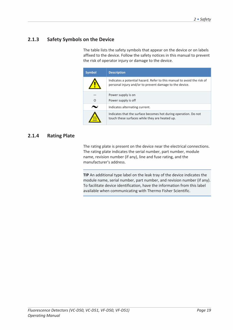
The table lists the safety symbols that appear on the device or on labelsaffixed to the device. Follow the safety notices in this manual to preventthe risk of operator injury or damage to the device.
Symbol Description
Indicates a potential hazard. Refer to this manual to avoid the risk ofpersonal injury and/or to prevent damage to the device.
—Ο
Power supply is onPower supply is off
Indicates alternating current.
Indicates that the surface becomes hot during operation. Do nottouch these surfaces while they are heated up.
2.1.4 Rating Plate
The rating plate is present on the device near the electrical connections.The rating plate indicates the serial number, part number, modulename, revision number (if any), line and fuse rating, and themanufacturer's address.
TIP An additional type label on the leak tray of the device indicates themodule name, serial number, part number, and revision number (if any).To facilitate device identification, have the information from this labelavailable when communicating with Thermo Fisher Scientific.

2 • Safety
Page 20 Fluorescence Detectors (VC-D50, VC-D51, VF-D50, VF-D51) Operating Manual
2.2 Intended UseThe device is intended to be part of the Vanquish system.
The intended use of the Vanquish system is to analyze mixtures ofcompounds in sample solutions.
The device is for use by qualified personnel and in laboratoryenvironment only.
The device and Vanquish system are intended to be used as GeneralLaboratory Equipment (GLE).
They are not intended for use in diagnostic procedures.
Laboratory Practice
Thermo Fisher Scientific recommends that the laboratory in which theVanquish system is used follow best practices for LC analyses. Thisincludes among others:
• Using appropriate standards
• Regularly running calibration
• Establishing shelf life limits and following them for all consumablesused with the system
• Running the system according to the laboratory's verified andvalidated 'lab developed test' protocol

2 • Safety
Fluorescence Detectors (VC-D50, VC-D51, VF-D50, VF-D51) Operating Manual
Page 21
2.3 Safety Precautions
2.3.1 General Safety Information
All users must observe the general safety information presented in thissection and all specific safety messages and precautionary statementselsewhere in this manual during all phases of installation, operation,troubleshooting, maintenance, shutdown, and transport of the device.
If the device is used in a manner not specified by Thermo FisherScientific, the protection provided by the device could be impaired.Observe the following:
• Operate the device only within its technical specifications.
• Use only the replacement parts and additional components, options,and peripherals specifically authorized and qualified for the deviceby Thermo Fisher Scientific.
• Perform only the procedures that are described in this operatingmanual and in supporting documents for the device. Follow allinstructions step by step and use the tools recommended for theprocedure.
• Open the enclosure of the device and other components only ifspecifically instructed to do so in this manual.
• Thermo Fisher Scientific cannot be held liable for any damage,material or otherwise, resulting from inappropriate or improper useof the device. If there is any question regarding appropriate usage,contact Thermo Fisher Scientific before proceeding.
Safety Standard
This device is a Safety Class I instrument (provided with terminal forprotective grounding). The device has been manufactured and testedaccording to international safety standards.
2.3.2 Qualification of the Personnel
Observe the information below on the proper qualification of thepersonnel installing and/or operating the device.

2 • Safety
Page 22 Fluorescence Detectors (VC-D50, VC-D51, VF-D50, VF-D51) Operating Manual
Installation
Only skilled personnel are permitted to install the device and toestablish the electrical connections according to the appropriateregulations.
• Thermo Fisher Scientific recommends always having servicepersonnel certified by Thermo Fisher Scientific perform theinstallation (for brevity, referred to as Thermo Fisher Scientificservice engineer).
• If a person other than a Thermo Fisher Scientific service engineerinstalls and sets up the module, the installer is responsible forensuring the safety of the module and system.
General Operation
The device is designed to be operated only by trained and qualifiedpersonnel in a laboratory environment.
All users must know the hazards presented by the device and thesubstances they are using. All users should observe the related SafetyData Sheets (SDSs).
2.3.3 Personal Protective Equipment
Wear personal protective equipment and follow good laboratorypractice to protect you from hazardous substances. The appropriateequipment depends on the hazard. For advice on the hazards and theequipment required for the substances you are using, refer to thematerial handling and safety data sheet provided by the vendor.
An eyewash facility and a sink should be available nearby. If anysubstance contacts your skin or eyes, wash the affected area and seekmedical attention.
Protective Clothing
To protect you from chemical splashes, harmful liquids, or othercontamination, put on appropriate protective clothing, such as a labcoat.
Protective Eyewear
To prevent liquids from striking your eyes, put on appropriate protectiveeyewear, such as safety glasses with side shields. If there is a risk ofsplashing liquids, put on goggles.

2 • Safety
Fluorescence Detectors (VC-D50, VC-D51, VF-D50, VF-D51) Operating Manual
Page 23
Gloves
To protect you from harmful liquids and avoid personal injury duringmaintenance or service, put on appropriate protective gloves.
2.3.4 Electrical Safety Precautions
WARNING—Electric Shock or Damage to the Device
High voltages are present inside the device that could cause an electricshock or damage to the device.
• Do not make any changes to the electrical or grounding connections.
• If you suspect any kind of electrical damage, disconnect the powercord and contact Thermo Fisher Scientific Technical Support forassistance.
• Do not open the housing or remove protective panels unlessspecifically instructed to do so in this manual.
• Do not place liquid reservoirs directly upon the device. Liquid mightleak into the device and get into contact with electronic componentscausing a short circuit. Instead, place liquid reservoirs in the solventrack that is available for the Vanquish system.
2.3.5 General Residual Hazards
Pay attention to the following general residual hazards when workingwith the device:

2 • Safety
Page 24 Fluorescence Detectors (VC-D50, VC-D51, VF-D50, VF-D51) Operating Manual
WARNING—Hazardous Substances
Solvents, mobile phases, samples, and reagents might contain toxic,carcinogenic, mutagenic, infectious, or otherwise harmful substances.The handling of these substances can pose health and safety risks.
• Be sure that you know the properties of all substances that you areusing. Avoid exposure to harmful substances. If you have any doubtabout a substance, handle the substance as if it is potentiallyharmful.
• Wear personal protective equipment as required by the hazard andfollow good laboratory practice.
• Reduce the volume of substances to the minimum volume requiredfor sample analysis.
• Do not operate the device in a potentially flammable environment.
• Avoid accumulation of harmful substances. Make sure that theinstallation site is well ventilated.
• Dispose of hazardous waste in an environmentally safe manner thatis consistent with local regulations. Follow a regulated, approvedwaste disposal program.
WARNING—Biohazard
Biohazardous material, for example microorganisms, cell cultures,tissues, body fluids, and other biological agents can transmit infectiousdiseases. To avoid infections with these agents:
• Assume that all biological substances are at least potentiallyinfectious.
• Wear personal protective equipment as required by the hazard andfollow good laboratory practice.
• Dispose of biohazardous waste in an environmentally safe mannerthat is consistent with local regulations. Follow a regulated,approved waste disposal program.
WARNING—Self-Ignition of Solvents
Solvents with a self-ignition temperature below 150 °C might ignitewhen in contact with a hot surface (for example, due to leakage in thechromatography system).
Avoid the use of these solvents.

2 • Safety
Fluorescence Detectors (VC-D50, VC-D51, VF-D50, VF-D51) Operating Manual
Page 25
WARNING—Hazardous Vapors
Mobile phases and samples might contain volatile or flammablesolvents. The handling of these substances can pose health and safetyrisks.
• Avoid accumulation of these substances. Make sure that theinstallation site is well ventilated.
• Avoid open flames and sparks.
• Do not operate the device in the presence of flammable gases orfumes.
CAUTION—Escape of Hazardous Substances from PEEK Capillaries
In the Vanquish system, capillaries made of PEEK may be used. Swellingor attack by acids can cause PEEK capillaries to start leaking or to burst.Certain chemicals, for example, trichlormethane (CHCl3), dimethylsulfoxide (DMSO), or tetrahydrofuran (THF) can cause PEEK to swell.Concentrated acids, such as sulfuric acid and nitric acid, or a mixture ofhexane, ethyl acetate, and methanol, can attack PEEK.
• Swelling or attack is not a problem with brief flushing procedures.
• For more information, refer to the technical literature on thechemical resistance of PEEK.
CAUTION—Allergic Reaction
Some capillaries in the Vanquish system are made of MP35N™, a nickel/cobalt-based alloy. Individuals with sensitivity to nickel/cobalt may showan allergic reaction from skin contact.
CAUTION—Sparking due to Electrostatic Discharge
Liquid flowing through capillaries can generate static electricity. Thiseffect is particularly present with insulating capillaries and non-conductive solvents (for example, pure acetonitrile). Discharge ofelectrostatic energy might lead to sparking, which could constitute a firehazard.
Prevent the generation of static electricity near the chromatographysystem.

2 • Safety
Page 26 Fluorescence Detectors (VC-D50, VC-D51, VF-D50, VF-D51) Operating Manual
2.3.6 In Case of Emergency
WARNING—Safety Hazard
In case of emergency, disconnect the device from the power line.

2 • Safety
Fluorescence Detectors (VC-D50, VC-D51, VF-D50, VF-D51) Operating Manual
Page 27
2.4 Solvent and Additive Information
2.4.1 General Compatibility
To protect optimal functionality of the Vanquish system, observe theserecommendations on the use of solvents and additives:
• The system must be used with reversed-phase (RP) compatiblesolvents and additives only.
• Use only solvents and additives that are compatible with all parts inthe flow path.
TIP In a Vanquish Core system, normal-phase (NP) compatible solventsand additives may be used if the VC-pumps and the VC-autosamplers aremodified with the components from the Normal-Phase (NP) kit. Refer tothe Operating Manuals for the pumps and autosamplers.
2.4.2 Allowed pH Ranges
Allowed pH ranges (standard system configuration):
System (StandardConfiguration)
AllowedpH ranges
Remarks
Vanquish Core 1-13 • pH values of 2 or less: The application time shouldbe as short as possible. Flush the systemthoroughly after these applications.
• pH values higher than 9.5 with optical detectors:Avoid using mobile phases with a pH value higherthan 9.5 together with optical detectors. This canimpair the functionality and optical performanceof the detector flow cell.
• pH values higher than 12: May affectelectrochemical detection. Before using highlyalkaline solvents for flushing the system,disconnect the detector from the system.
• Mobile phases containing ammonium hydroxide: Inrare cases, a shortened lifetime of reversed-phase(UHMW-PE) piston seals has been observed withhigh pH, ammonium hydroxide containing mobilephases and prolonged exposure.
VanquishHorizonVanquish Flex
2-12

2 • Safety
Page 28 Fluorescence Detectors (VC-D50, VC-D51, VF-D50, VF-D51) Operating Manual
2.4.3 Allowed Concentrations
Allowed concentrations (standard system configuration):
System (StandardConfiguration)
Chloride Buffer Remarks
Vanquish Core 0.1 mol/Lor less
1 mol/L orless
• High chloride concentration:The application time should beas short as possible. Flush thesystem thoroughly after theseapplications.
• Mobile phases containingammonium hydroxide: In rarecases, a shortened lifetime ofreversed-phase (UHMW-PE)piston seals has been observedwith high pH, ammoniumhydroxide containing mobilephases and prolongedexposure.
Vanquish HorizonVanquish Flex
1 mol/L orless
-
2.4.4 Further Information
• For details about the materials that are used in the analytical flowpath of the device, see the Specifications chapter in this manual. Forinformation about the materials that are used in the flow path of theother modules in the Vanquish system, refer to the Specificationschapter in the Operating Manual for the modules.
• Follow any specific recommendations presented in other sections ofthis manual. Refer also to the operating manuals for all modules inthe Vanquish system. They may provide additional guidelines andinformation.
• Observe the general guidelines and recommendations on the use ofsolvents and additives in the chromatography system. Refer to Useof Solvents and Additives in the Vanquish System Operating Manual.

2 • Safety
Fluorescence Detectors (VC-D50, VC-D51, VF-D50, VF-D51) Operating Manual
Page 29
2.5 Compliance InformationThermo Fisher Scientific performs complete testing and evaluation of itsproducts to ensure full compliance with applicable domestic andinternational regulations. When the device is delivered to you, it meetsall pertinent electromagnetic compatibility (EMC) and safety standardsas described in this manual.
Changes that you make to the device may void compliance with one ormore of these EMC and safety standards. Changes to the device includereplacing a part or adding components, options, or peripherals notspecifically authorized and qualified for the product by Thermo FisherScientific. To ensure continued compliance with EMC and safetystandards, replacement parts and additional components, options, andperipherals must be ordered from Thermo Fisher Scientific or one of itsauthorized representatives.
The device has been shipped from the manufacturing site in a safecondition.
See also
2 Compliance Information ( page 178)

2 • Safety
Page 30 Fluorescence Detectors (VC-D50, VC-D51, VF-D50, VF-D51) Operating Manual

3 • Device Overview
Fluorescence Detectors (VC-D50, VC-D51, VF-D50, VF-D51) Operating Manual
Page 31
3 Device OverviewThis chapter introduces you to the device and the main components.

3 • Device Overview
Page 32 Fluorescence Detectors (VC-D50, VC-D51, VF-D50, VF-D51) Operating Manual
3.1 Detector FeaturesThe device comprises the following main features:
• A xenon flash lamp for the complete excitation wavelength rangefrom 200 nm to 880 nm as the light source of the device
• An optional second photomultiplier tube (PMT) to extend theemission wavelength range to the near-infrared spectral region (upto 900 nm) without any loss in sensitivity in the UV/VIS spectralregion
• Data collection rates in single channel mode of up to 100 Hz (VCdetectors) or 200 Hz (VF detectors under Chromeleon 7 software)
• A wavelength switching time < 250 ms
• Optimized detection for high sensitivity (signal-to-noise ratio higherthan 550 for the Raman spectrum of water at 350 nm excitation),over the entire lifetime of the lamp. It is thus possible to detect evensmallest peaks.
• Flow cells equipped with an active temperature control to ensureimproved reproducibility when ambient temperature fluctuates
• A cut-off filter to suppress the higher-order radiation typical ofgrating spectrometers and scattering of light. For VF detectors, afilter wheel can be moved to 5 different positions with the help of amotor.
• Measurement of up to 4 data channels (VF detectors only) withindependent parameter settings (PMT selection, wavelengths,sensitivity, filter wheel).

3 • Device Overview
Fluorescence Detectors (VC-D50, VC-D51, VF-D50, VF-D51) Operating Manual
Page 33
3.2 Operating PrincipleFluorescence detectors are optical detectors. In a fluorescence detector,the sample is exposed to light at a defined wavelength. The light isabsorbed by the sample substance and causes the substance to beplaced in an excited state (excitation). As the sample substance returnsto its ground state, it emits light at a higher wavelength (emission). Thephotomultiplier tube (PMT) is positioned at an angle of 90° to the lightsource and detects the light that was emitted from the fluorescingsubstances.
In contrast to UV/VIS detectors, a fluorescence detector measures a veryweak light signal rather than the difference between light intensities(absorbance).
Absorption of light
Figure 1: Simplified presentation of a molecule absorbing light
Emission oflight of a longerwavelength
Figure 2: Simplified presentation of a molecule emitting light(fluorescence)
3 • Device Overview
Page 34 Fluorescence Detectors (VC-D50, VC-D51, VF-D50, VF-D51) Operating Manual
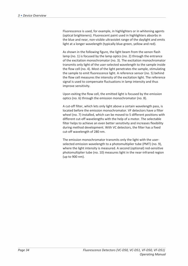
Fluorescence is used, for example, in highlighters or in whitening agents(optical brighteners). Fluorescent paint used in highlighters absorbs inthe blue and near, non-visible ultraviolet range of the daylight and emitslight at a longer wavelength (typically blue-green, yellow and red).
As shown in the following figure, the light beam from the xenon flashlamp (no. 1) is focused by the lamp optics (no. 2) through the entranceof the excitation monochromator (no. 3). The excitation monochromatortransmits only light of the user-selected wavelength to the sample insidethe flow cell (no. 4). Most of the light penetrates the sample, stimulatingthe sample to emit fluorescence light. A reference sensor (no. 5) behindthe flow cell measures the intensity of the excitation light. The referencesignal is used to compensate fluctuations in lamp intensity and thusimprove sensitivity.
Upon exiting the flow cell, the emitted light is focused by the emissionoptics (no. 6) through the emission monochromator (no. 8).
A cut-off filter, which lets only light above a certain wavelength pass, islocated before the emission monochromator. VF detectors have a filterwheel (no. 7) installed, which can be moved to 5 different positions withdifferent cut-off wavelengths with the help of a motor. The selectablefilter helps to achieve an even better sensitivity and increases flexibilityduring method development. With VC detectors, the filter has a fixedcut-off wavelength of 280 nm.
The emission monochromator transmits only the light with the user-selected emission wavelength to a photomultiplier tube (PMT) (no. 9),where the light intensity is measured. A second (optional) red-sensitivephotomultiplier tube (no. 10) measures light in the near-infrared region(up to 900 nm).

3 • Device Overview
Fluorescence Detectors (VC-D50, VC-D51, VF-D50, VF-D51) Operating Manual
Page 35
Figure 3: Optics Setup (schematic)
No. Component Description
1 Xenon flash lamp Light source for the UV to near-infrared wavelengthrange
2 Lamp optics Focuses the light beam emitted from the xenon flashlamp so that the beam passes through the excitationmonochromator
3 Excitationmonochromator
Lets only light with the selected excitation wavelengthpass
4 Flow cell The eluent with the analyte travels through the flowcell. The excitation light passes the flow cell to thereference sensor, the fluorescence light exits the flowcell at an angle of 90° to the excitation light.
5 Reference sensor Measures the excitation light that passes the flow celland is used to compensate lamp fluctuations
6 Emission optics Focuses the light beam emitted from the flow cell sothat the beam passes through the emissionmonochromator
7 Filter wheel Carries the optical filters, which are used to cut off lightbelow the cut-off wavelength of the selected filter
8 Emissionmonochromator
Lets only light with the selected emission wavelengthpass
9 Photomultipliertube (PMT)
Converts light into a measurable current
10 Second PMT Measures light in the near-infrared region (up to900 nm)

3 • Device Overview
Page 36 Fluorescence Detectors (VC-D50, VC-D51, VF-D50, VF-D51) Operating Manual
3.3 Interior ComponentsThe user-accessible components of the device are located directlybehind the front doors:
Figure 4: Interior view (here with flow cell installed)
No. Description
1 Cooling air intake
2 Keypad with status indicators
3 Flow cell
4 Leak tray with leak sensor
5 Partition panelThe recesses in the partition panel are used to route capillaries with thehelp of special plugs.
6 Type label, indicating the module name, serial number, part number, andrevision number (if any)
7 Leak sensor
8 Capillary clips

3 • Device Overview
Fluorescence Detectors (VC-D50, VC-D51, VF-D50, VF-D51) Operating Manual
Page 37
3.4 Flow CellThe detector design allows easy access to the flow cell on the interiorfront.
Figure 5: Flow cell (example)
No. Description
1 Flow cell screws - Used to mount the flow cell to the detector.
2 Flow cell label
3 Outlet - Used to connect the waste line.
4 Inlet - Used to connect the inlet capillary.
55a, 5b, 5c
Optical block - Do not touch the optical block.Optical ports
Flow Cell Label
One or more flow cell labels are present on the flow cell, which containinformation such as flow cell type, part number, and serial number.
Flow Cell Identification Chip
An identification (ID) chip on the flow cell stores information, includingthe flow cell type and the serial number of the flow cell. The ID chip alsostores data during operation, such as the exposure time to the light.
When the flow cell is installed and the front doors are closed, the devicereads the data from the chip and transfers the flow cell data to theChromeleon software.

3 • Device Overview
Page 38 Fluorescence Detectors (VC-D50, VC-D51, VF-D50, VF-D51) Operating Manual
Temperature Control
The flow cells are equipped with a temperature control unit. Flow celland heat exchanger can be heated to a user-defined temperature.
The heat exchanger helps to adapt the temperature of the mobile phaseto the flow cell temperature before the mobile phase enters the opticalflow path within the flow cell. Note that the volume of the heatexchanger and inlet capillary influences the retention times and peakwidths.
Flow Cell Types
All flow cells are optimized for fast separations with no loss inchromatographic resolution. To ensure optimum performance of theflow cells, observe the guidelines in Guidelines for Use of Flow Cells( page 98).
For details about the flow cells or about the availability of other flowcells, refer to the Thermo Fisher Scientific sales organization.
For flow cell ordering information, see Optional Accessories( page 174).
For the flow cell specifications, including materials in the flow path andtemperature range, see Flow Cells ( page 168).

3 • Device Overview
Fluorescence Detectors (VC-D50, VC-D51, VF-D50, VF-D51) Operating Manual
Page 39
3.5 LampThe light source is a xenon flash lamp.
Figure 6: Xenon flash lamp
• The lamp is turned on when data acquisition starts, andautomatically turned off after data acquisition was stopped toextend its lifetime.
• The flash frequency of the lamp varies, depending on the selectedlamp mode. Selecting a different lamp mode during phases when nopeaks of interest elute can extend the lamp lifetime.
• You can monitor the lamp age. This function can help to decidewhen a lamp is due to be replaced.
• The lamp must be replaced by a Thermo Fisher Scientific serviceengineer.
For details on the available lamp modes and how to extend the lamplifetime, see Lamp Mode ( page 115).
For details on monitoring the lamp age, see Monitoring the Lamp Age( page 131).

3 • Device Overview
Page 40 Fluorescence Detectors (VC-D50, VC-D51, VF-D50, VF-D51) Operating Manual
3.6 Leak DetectionLeaks are a potential safety issue.
The leak sensor inside the device monitors the device for liquid leaksfrom the flow connections. The liquid is collected in the leak tray andguided to the drain port. From the drain port, the liquid is discharged towaste through the drain system of the Vanquish system.
When the leak sensor detects leakage, the status indicators change tored and beeping starts to alert you. Follow the instructions in thismanual to find and eliminate the source for the leakage.

3 • Device Overview
Fluorescence Detectors (VC-D50, VC-D51, VF-D50, VF-D51) Operating Manual
Page 41
3.7 OperationThe device is designed to be operated from a computer configured withthe Chromeleon Chromatography Data System (CDS). The Chromeleonsoftware provides complete instrument control, data acquisition, anddata management.
For a basic description of instrument control and automated sampleanalysis with the Chromeleon software, refer to the Vanquish SystemOperating Manual. Details on control and operation of the device areavailable in the Chromeleon Help.
TIP The device can be operated also with other data systems, such asThermo ScientificTM XcaliburTM. In this case, installation of additionalsoftware is required in addition to the data system software. For details,contact the Thermo Fisher Scientific sales organization.
A keypad is available inside the detector, allowing you to mute an alarmand initialize the device directly from the detector.

3 • Device Overview
Page 42 Fluorescence Detectors (VC-D50, VC-D51, VF-D50, VF-D51) Operating Manual

4 • Unpacking
Fluorescence Detectors (VC-D50, VC-D51, VF-D50, VF-D51) Operating Manual
Page 43
4 UnpackingThis chapter provides information for unpacking the device and informsyou about the scope of delivery.

4 • Unpacking
Page 44 Fluorescence Detectors (VC-D50, VC-D51, VF-D50, VF-D51) Operating Manual
4.1 UnpackingDamaged Packaging, Defective on Arrival
Inspect the shipping container for signs of external damage and, afterunpacking, inspect the device for any signs of mechanical damage thatmight have occurred during shipment.
If you suspect that the device may have been damaged during shipment,immediately notify the incoming carrier and Thermo Fisher Scientificabout the damage. Shipping insurance will compensate for the damageonly if reported immediately.
Unpacking the Device
CAUTION—Heavy Load, Bulky Device
The device is too heavy or bulky for one person alone to handle safely.To avoid personal injury or damage to the device, observe the followingguidelines:
• Physical handling of the device, including lifting or moving, requiresa team effort of two persons.
• A team effort is in particular required when lifting the device intothe system stack or when removing it.
• Use the carrying handles that were shipped with the device to moveor transport the device. Never move or lift the device by the frontdoors. This will damage the doors or the device.
Tools required
Screwdriver, Torx™ T20
Follow these steps
1. Place the shipping container on the floor and open it.
2. Remove the ship kit from the shipping container.
3. Remove the device from the shipping container: Grasp the device bythe carrying handles. Slowly and carefully, lift the device out of theshipping container.

4 • Unpacking
Fluorescence Detectors (VC-D50, VC-D51, VF-D50, VF-D51) Operating Manual
Page 45
Figure 7: Carrying handles on the device
No. Component
1 Carrying handles
2 Attachment screw (one on each carrying handle)
4. Place the device on a stable surface.
5. If applicable:Remove any additional packing material. Leave any protective filmsattached to the surfaces of the device until it is properly positionedin the system stack.
6. Transport the device by the carrying handles to the installation site,if it is not already there, and place it in the system stack (see SystemArrangement ( page 54)).
7. On each carrying handle, loosen the attachment screw until thecarrying handle is moveable in the rail. Do not remove the screwsfrom the carrying handles completely.
8. Slide off the carrying handles from the rails towards the rear of thedevice.
Figure 8: Sliding off the carrying handle from the left rail
TIP Keep the shipping container, the carrying handles with theattachment screws, and all packing material. These items will be neededif the device is transported to a new location or shipped.
9. Some surfaces including the doors of the device are covered by aprotective film during shipment. Remove the protective film from allsurfaces as applicable.

4 • Unpacking
Page 46 Fluorescence Detectors (VC-D50, VC-D51, VF-D50, VF-D51) Operating Manual
4.2 Scope of DeliveryThe following items are included in the delivery:
• Detector
• Ship Kit
• Operating manual
• Power cord
For information on contents of the ship kit or reordering parts, seeAccessories, Consumables and Replacement Parts ( page 171).

5 • Installation
Fluorescence Detectors (VC-D50, VC-D51, VF-D50, VF-D51) Operating Manual
Page 47
5 InstallationThis chapter specifies the requirements for the installation site anddescribes how to set up, install, and configure the device in the Vanquishsystem and in the chromatography software.

5 • Installation
Page 48 Fluorescence Detectors (VC-D50, VC-D51, VF-D50, VF-D51) Operating Manual
5.1 Safety Guidelines for InstallationPay attention to the following safety guidelines:
Observe all warning messages and precautionary statements presentedin Safety Precautions ( page 21).
CAUTION—Heavy Load, Bulky Device
The device is too heavy or bulky for one person alone to handle safely.To avoid personal injury or damage to the device, observe the followingguidelines:
• Physical handling of the device, including lifting or moving, requiresa team effort of two persons.
• A team effort is in particular required when lifting the device intothe system stack or when removing it.
• Use the carrying handles that were shipped with the device to moveor transport the device. Never move or lift the device by the frontdoors. This will damage the doors or the device.
CAUTION—Electric Shock or Damage to the Device
After the power to the device is turned off, the device is still energizedas long as the power cord is connected. Repair work on the device whilethe device is connected to power could lead to personal injury.
• Always unplug the power cord before starting repair work inside thedevice.
• If you were instructed to remove any housing covers or panels, donot connect the power cord to the device while the cover or panelsare removed.

5 • Installation
Fluorescence Detectors (VC-D50, VC-D51, VF-D50, VF-D51) Operating Manual
Page 49
5.2 Installing the DeviceThe Vanquish system is installed and set up by a Thermo Fisher Scientificservice engineer, including all modules and options or parts shipped withthem. The service engineer checks that the installation is correct andthat the Vanquish system and modules operate as specified. Theengineer also demonstrates the basic operation and main features.
If personnel other than a Thermo Fisher Scientific service engineerinstalls the device, follow the steps below.
NOTICE
The device is part of the Vanquish system. Therefore, follow the orderfor installing the system modules as described in the Vanquish SystemOperating Manual.
1. Pay attention to the safety guidelines and observe all siterequirements. See Safety Guidelines for Installation ( page 48) andSite Requirements ( page 51).
2. Set up the device hardware. See Setting Up the Hardware( page 54).
3. Set up the flow connections. See Setting Up the Flow Connections( page 64).
4. Turn on the device. See Turning On the Device ( page 86).
TIP
Before turning on the power to a Vanquish system module for the firsttime, verify that the chromatography software is installed on the datasystem computer. When the power is turned on, the required USBdrivers are automatically found and the Windows™ operating systemcan detect the device.
5. Set up the device in the software. See Setting Up the Device in theSoftware ( page 87).
6. Perform a wavelength calibration and wavelength validation.

5 • Installation
Page 50 Fluorescence Detectors (VC-D50, VC-D51, VF-D50, VF-D51) Operating Manual
7. Recommended:Perform Instrument Installation Qualification.
In the Chromeleon software, a wizard is available to guide youthrough the qualification process. On the Chromeleon 7 Console:Click Tools > Instrument Qualification > Installation Qualification.
Follow the instructions in the Instruments Installation QualificationOperating Instructions. The manual provides information about therequired materials and detailed instructions.
NOTICE
If the device is operated with another data system, refer to thedocumentation for the software that you are using and/or perform thequalification manually. The Instruments Installation QualificationOperating Instructions provide information about the parameters to beadapted and the required settings.
8. Recommended: Perform Operational Qualification.The qualification kit includes all materials required for thequalification and detailed instructions.
Moving the Device after Installation
If you have to move the device after it has been set up and installed inthe Vanquish system, prepare the device for transport and move it tothe new location. Follow the instructions in Transporting or Shipping theDevice ( page 146).
See also
2 Performing a Wavelength Calibration ( page 132)
2 Performing a Wavelength Validation ( page 134)
5 • Installation
Fluorescence Detectors (VC-D50, VC-D51, VF-D50, VF-D51) Operating Manual
Page 51
5.3 Site RequirementsThe operating environment is important to ensure optimal performanceof the device. This section provides important requirements for theinstallation site. Note the following:
• Operate the device only under appropriate laboratory conditions.
• The device is intended to be part of the Vanquish system. Observethe site requirements for the Vanquish system as stated in theVanquish System Operating Manual.
• For specifications, see Specifications ( page 165) and theSpecifications sections in the Operating Manuals for the othermodules in the Vanquish system.
• For general residual hazards, see General Residual Hazards( page 23).
5.3.1 Power Considerations
The power supply of the device has wide-ranging capability, acceptingany line voltage in the range specified for the device.
CAUTION—Electric Shock or Damage to the Device
Connecting the device to a line voltage higher or lower than specifiedcould result in personal injury or damage to the device.
Connect the device to the specified line voltage only.
5.3.2 Power Cord
The power cords are designed to match the wall socket requirements ofthe country in which they are used. The end of the power cords thatplugs into the power socket on the device is identical for all power cords.The end of the power cords that plugs into the wall socket is different.

5 • Installation
Page 52 Fluorescence Detectors (VC-D50, VC-D51, VF-D50, VF-D51) Operating Manual
WARNING—Electric Shock or Damage to the Device
• Never use a power cord other than the power cords provided byThermo Fisher Scientific for the device.
• Only use a power cord that is designed for the country in which youuse the device.
• Do not use extension cords.
• Never plug the power cord to a power socket that is shared withother equipment (for example, multiple sockets).
• Operate the device only from a power outlet that has a protectiveground connection.
• In case of emergency, it must be possible to reach the power cordeasily at any time to disconnect the device from the power line.
WARNING—Electric Shock or Damage to a Product
Misuse of the power cords could cause personal injury or damage theinstrument. Use the power cords provided by Thermo Fisher Scientificonly for the purpose for which they are intended. Do not use them forany other purpose, for example, for connecting other instruments.
5.3.3 Condensation
NOTICE—Condensation in the device can damage the electronics andoptics.
• When using, shipping, or storing the device, avoid or minimizeconditions that can lead to a build-up of condensation in the device.For example, avoid significant or fast changes in environmentalconditions.
• If you suspect that condensation is present, allow the device towarm up to room temperature. This may take several hours. Waituntil the condensation is gone completely before connecting thedevice to the power line.

5 • Installation
Fluorescence Detectors (VC-D50, VC-D51, VF-D50, VF-D51) Operating Manual
Page 53
5.4 Accessing the Interior ComponentsTo access the interior components in the device, open the front doors.To allow easy access from the front, the user-accessible components andflow connections in the device are located directly behind the doors.
Figure 9: Opening the front doors

5 • Installation
Page 54 Fluorescence Detectors (VC-D50, VC-D51, VF-D50, VF-D51) Operating Manual
5.5 Setting Up the HardwareThis section describes how to set up the hardware and providesinformation about the device connectors and cables.
5.5.1 System Arrangement
The device is part of the Vanquish system. The system modules aretypically arranged in a system stack, with the arrangement depending onthe system configuration.
The following illustrations show configurations with a singlefluorescence detector, and with a fluorescence detector as a seconddetector on top of a UV/VIS detector.
TIP
Due to the pressure limit of the flow cell, the fluorescence detectorshould be the last module in the fluidic path whenever possible.
For instructions on how to set up the system stack, refer to the VanquishSystem Operating Manual.

5 • Installation
Fluorescence Detectors (VC-D50, VC-D51, VF-D50, VF-D51) Operating Manual
Page 55
System with Single Detector
Figure 10: Vanquish system, standard configuration (example)
No. Description
1 Solvent Rack
2 Fluorescence detector
3 Autosampler
4 Pump
5 System Base
6 Column Compartment

5 • Installation
Page 56 Fluorescence Detectors (VC-D50, VC-D51, VF-D50, VF-D51) Operating Manual
System with Fluorescence Detector as Second Detector
Figure 11: Vanquish system, configuration with two detectors (example)
No. Description
1 Solvent Rack
2 Fluorescence Detector
3 UV/VIS Detector
4 Autosampler
5 Pump
6 System Base
7 Column Compartment

5 • Installation
Fluorescence Detectors (VC-D50, VC-D51, VF-D50, VF-D51) Operating Manual
Page 57
5.5.2 Connecting the Device
Device Connectors
The following connectors are provided on the device:
Figure 12: Electrical connectors on the right side of the detector
No. Description
1 Rating plate, indicating the serial number, part number, module name,revision number (if any), line and fuse rating, and the manufacturer'saddress
2 Main power switch (on/off control)
3 Fuse holder
4 Power-inlet connector
5 System Interlink portAllows power on/off control for the detector from the Vanquish systembase and device communication and synchronization between the detectorand other modules in the Vanquish system.For example, the interconnection between autosampler and detectorautomatically enables direct synchronization of sample inject and dataacquisition start in the detector. As a result, the synchronization improvesthe retention time reproducibility.

5 • Installation
Page 58 Fluorescence Detectors (VC-D50, VC-D51, VF-D50, VF-D51) Operating Manual
No. Description
6 Digital I/O ports (Dig I/O)Allow exchange of digital signals with externalinstrumentsEach digital I/O port provides one input and one relay output. Forconnection and pin assignment information, see Digital I/O ( page 181).
7 USB hub ("A"-type connector)Allows connection to other modules in the Vanquish system
8 USB (Universal Serial Bus) port ("B" type connector)Allows connection to other modules in the Vanquish system or thecomputer on which the data management system is installed, such as theChromeleon software
TIP Thermo Fisher Scientific recommends using the USB ports only asdescribed above. If the USB ports are used for any other purpose,Thermo Fisher Scientific cannot ensure proper functionality.
Follow these steps
NOTICE
• Never use defective communication cables. If you suspect that acable is defective, replace the cable.
• To ensure trouble-free operation, use only the cables provided byThermo Fisher Scientific for connecting the device.
1. Place the device in the system as required by the systemconfiguration. For details, refer to the Vanquish System OperatingManual.
2. Connect the required interface cables to the device.
3. Connect the power cord (see Connecting the Power Cord( page 61)).
See also
2 Connecting the Interface Cables ( page 59)

5 • Installation
Fluorescence Detectors (VC-D50, VC-D51, VF-D50, VF-D51) Operating Manual
Page 59
5.5.2.1 Connecting the Interface Cables
The connection of the interface cables depends on whether the detectoris used as the only detector or as a second detector in the Vanquishsystem.
The Detector is the only Detector in the System
Connect the required interface cables to the detector. For informationabout how to connect the detector to other modules in the Vanquishsystem or to the chromatography data system computer, refer to theVanquish System Operating Manual.
The Detector is the Second Detector in the System
If the fluorescence detector is the second detector in the Vanquishsystem (for example, after the diode array detector), set up the USB andsystem interlink connections as shown in the figure.
1. Follow the instructions in the Vanquish System Operating Manual toconnect the other modules in the system up to the diode arraydetector.
2. Connect a USB cable from a free USB port on the diode arraydetector to the fluorescence detector.
3. Connect a system interlink cable from the free System Interlink porton the diode array detector to the fluorescence detector.
4. Connect a system interlink cable from the free System Interlink porton the diode array detector to the column compartment.

5 • Installation
Page 60 Fluorescence Detectors (VC-D50, VC-D51, VF-D50, VF-D51) Operating Manual
Figure 13: Cable connections in the Vanquish system with fluorescencedetector and diode array detector (example)
No. Description
1 System base
2 Pump
3 Sampler
4 Diode array detector
5 Fluorescence detector
6 Column compartment
7 Connection to computer

5 • Installation
Fluorescence Detectors (VC-D50, VC-D51, VF-D50, VF-D51) Operating Manual
Page 61
5.5.2.2 Connecting the Power Cord
NOTICE
Condensation in a device can damage the electronics.
• Before connecting the devices to the power line, be sure that nocondensation is present in the devices.
• If you suspect that condensation is present, allow the device towarm up to room temperature slowly. Wait until the condensation iscompletely gone before proceeding.
1. Verify that the power switch on the device is set to OFF.
2. Connect the power cord to the power inlet connector on the device.
3. Connect the free end of the power cord to an appropriate powersource.
5.5.3 Installing the Flow Cell
This section describes the installation of the flow cell upon initialinstallation of the detector.
For instructions on removing a flow cell or installing a flow cell afterstorage, see Flow Cell ( page 136).
NOTICE
Flow cells are highly sensitive to dirt and dust. Observe the followingnotes when installing the flow cell to the detector:
• When holding flow cells, do not touch the optical block of the flowcell or the sensitive electronics on the flow cell rear side.
• The optical ports of the flow cell are sensitive to contamination andscratches. Do not touch the optical ports of the flow cell or immersethem.
• To avoid damage to the optical ports of the flow cell, be carefulwhen inserting the flow cell into the flow cell opening of the device.
• Use the dedicated packaging when storing or transporting the flowcell.
• On the rear side of the flow cell, the contact pads for theidentification chip are located. Never touch the contact pads. Avoiddamage to the electronics of the ID chip.

5 • Installation
Page 62 Fluorescence Detectors (VC-D50, VC-D51, VF-D50, VF-D51) Operating Manual
Parts required
Flow cell
Preparations
1. Remove the cover from the flow cell opening. To do so, loosen thetwo finger-tight screws. The screws are captive in the cover and donot need to be removed.
TIP Keep the cover to close the flow cell opening when no flow cell isinstalled in the device, especially when the detector is transported orshipped.
2. Unpack the flow cell.
Figure 14: Flow cell of the fluorescence detector
No. Description
1 Flow cell screws - Used to mount the flow cell to the detector.
2 Flow cell label
3 Outlet - Used to connect the waste line.
4 Inlet - Used to connect the inlet capillary.
55a, 5b, 5c
Optical block - Do not touch the optical block.Optical ports

5 • Installation
Fluorescence Detectors (VC-D50, VC-D51, VF-D50, VF-D51) Operating Manual
Page 63
Follow these steps
1. Insert the flow cell straight into the flow cell opening.
Figure 15: Inserting the flow cell
2. Tighten the flow cell screws hand-tight.

5 • Installation
Page 64 Fluorescence Detectors (VC-D50, VC-D51, VF-D50, VF-D51) Operating Manual
5.6 Setting Up the Flow Connections
5.6.1 General Information and Guidelines
When setting up flow connections, follow these rules andrecommendations:
Flow connections can be filled with hazardous substances. Observe thewarning messages and precautionary statements presented in SafetyPrecautions ( page 21).
NOTICE
Particulate matter from other system modules and components candeposit in the flow cell and clog it.
• Before you connect the flow cell to the flow path, make sure thatyou thoroughly flush the modules in the system flow path upstreamof the device to waste.
• When you install devices or components to the system, always flushthem to waste before connecting them in the system flow path. Toflush the Vanquish modules, follow the instructions in the VanquishSystem Operating Manual.
NOTICE
Flow cells are highly sensitive to contamination, clogging and highbackpressures. Even if the pressure exceeds the upper limit for a veryshort time only, the flow cell may be permanently damaged. Observethe following notes when connecting the flow cell to the system flowpath:
• When connecting a component in the flow path after the flow cell,observe the specified backpressure for the flow cell.
• Use only clean Viper capillaries which were provided for the flow celland which have been properly protected by their cap before.
• Use only the waste line which was provided for the flow cell.
• Avoid clogging of the flow cell or waste line.
• Improperly set up flow connections can lead to leaks on the flow cellor even destroy the flow cell. Do not invert the flow cell inlet andoutlet.

5 • Installation
Fluorescence Detectors (VC-D50, VC-D51, VF-D50, VF-D51) Operating Manual
Page 65
• Operating switching valves, fraction collectors, mass spectrometers,or a second detector downstream of the flow cell under flow willresult in pressure spikes that can destroy the flow cell. If using thosedevices, you need to install an overpressure relief valve (available asan accessory for the Micro flow cell, opens at 4 MPa (40 bar)). Evenif you use an overpressure relief valve, switching flows may damagethe flow cell. Switch the flow rarely and only if it is absolutelynecessary.
Follow these steps
To set up the flow connections and complete the installation of thedevice, follow these steps:
1. Set up the flow connections to the flow cell (see Flow Connectionsto the Flow Cell ( page 71)).
2. Connect the device to the drain system (refer to the VanquishSystem Operating Manual).
For installation instructions, guidelines, and handling recommendations,see Connecting Fittings, Capillaries, and Tubing ( page 68).
5.6.2 Guiding Capillaries and Tubing Through the System
Flow connections between the modules of the Vanquish system areguided through either the tubing chase in the devices or the guide holesor capillary clips of the devices.
Tubing Chase, Tubing Guide, Tubing Bracket
To guide certain tubes and lines (solvent tubing, wash liquid tubing,detector waste line) from the top module to the bottom module in theVanquish system stack, the stackable modules have a tubing chase onthe inside right.
The tubing chase provides four tubing guides. Each guide can hold up tothree tubes or lines.
In each module, push the tube (or line) into the appropriate guide.
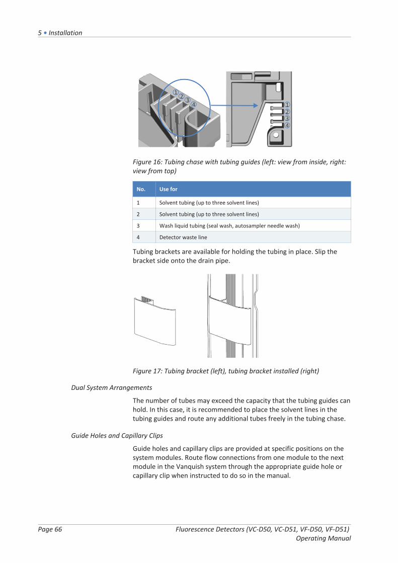
5 • Installation
Page 66 Fluorescence Detectors (VC-D50, VC-D51, VF-D50, VF-D51) Operating Manual
Figure 16: Tubing chase with tubing guides (left: view from inside, right:view from top)
No. Use for
1 Solvent tubing (up to three solvent lines)
2 Solvent tubing (up to three solvent lines)
3 Wash liquid tubing (seal wash, autosampler needle wash)
4 Detector waste line
Tubing brackets are available for holding the tubing in place. Slip thebracket side onto the drain pipe.
Figure 17: Tubing bracket (left), tubing bracket installed (right)
Dual System Arrangements
The number of tubes may exceed the capacity that the tubing guides canhold. In this case, it is recommended to place the solvent lines in thetubing guides and route any additional tubes freely in the tubing chase.
Guide Holes and Capillary Clips
Guide holes and capillary clips are provided at specific positions on thesystem modules. Route flow connections from one module to the nextmodule in the Vanquish system through the appropriate guide hole orcapillary clip when instructed to do so in the manual.

5 • Installation
Fluorescence Detectors (VC-D50, VC-D51, VF-D50, VF-D51) Operating Manual
Page 67
5.6.3 Installing the Partition Panel Plugs
There are two types of partition panel plugs available in the detectorship kit.
Figure 18: Plugs available for the partition panel
No. Description
1 Plug with slit, for guiding capillaries with small outer diameter, such asuninsulated capillaries.
2 Rotating plug, for guiding capillaries that do not fit in the plug with slit,including insulated capillaries.
Installing the plug with slit
1. On the detector partition panel, push the plug with slit in therequired recess of the partition panel (if not present yet).
2. To secure the plug with slit, insert the nose into the opening of thepartition panel.
Figure 19: Securing the partition panel plug with slit
3. To secure the capillary, push the capillary into the slit of the plug.

5 • Installation
Page 68 Fluorescence Detectors (VC-D50, VC-D51, VF-D50, VF-D51) Operating Manual
Figure 20: Capillary installed in the plug with slit
Installing the rotating plug
1. On the detector partition panel, push the rotating plug in therequired recess of the partition panel (if not present yet).
2. To open the plug in order to route the capillary through the plug,turn the rotating plug toward the front.
3. To secure the capillary, turn the rotating plug toward the partitionpanel to close the opening of the rotating plug.
Figure 21: Using the rotating plug
5.6.4 Connecting Fittings, Capillaries, and Tubing
The inlet and outlet ports of the flow cells support the following capillaryfittings:
• Viper™
• nanoViper™
• Standard 1/16" HPLC fittings using ferrules (PEEK, SST) or finger-tightfittings (PEEK)
This section provides information about how to connect and handlecapillaries, fittings, and tubing.
5 • Installation
Fluorescence Detectors (VC-D50, VC-D51, VF-D50, VF-D51) Operating Manual
Page 69
5.6.4.1 General Guidelines
When connecting capillaries and tubing, follow these generalrecommendations:
• Use only the capillaries and tubing (for example, solvent lines orwaste tubing) that are shipped with the product or additional orspare capillaries and tubing as recommended by Thermo FisherScientific.
• The connectors must be free from contaminants. Even minuteparticles may cause damage to the system or lead to invalid testresults.
• Do not install capillaries or tubes that are stressed, nicked, kinked, orotherwise damaged.
• Install capillaries and fittings only at the positions for which they areintended.
5.6.4.2 Connecting Viper Capillaries
This section describes how to connect Viper™ capillaries. All Viper flowconnections in the Vanquish system are designed to be finger-tight.
To connect Viper capillaries with knurls, follow these steps:
NOTICE
• Tighten or loosen Viper capillaries only with your fingers. Do not usetools other than the knurl that comes with the capillary.
• To avoid damage to the capillary or connection, tighten and loosenthe Viper capillaries only when the system pressure is down to zero.

5 • Installation
Page 70 Fluorescence Detectors (VC-D50, VC-D51, VF-D50, VF-D51) Operating Manual
Figure 22: Viper fitting with knurl
No. Description
1 Knurl
2 Capillary
3 Slot
1. Insert the Viper capillary into the connection port.
2. Tighten the connection by the knurl.
TIP Note the slot in the knurl. For narrow connections, you can easilyremove the knurls from neighboring capillaries through this slot andattach them again later.
3. Check whether the connection leaks. If leakage exists, follow thesteps further down.
Resolving Leakage of Viper Fittings with Knurls
1. Tighten the connection a little more.
2. If leakage continues, remove the capillary.
3. Clean the capillary ends carefully by using a lint-free tissue wettedwith isopropanol.
4. Reinstall the capillary.
5. If the connection continues to leak, install a new Viper capillary.

5 • Installation
Fluorescence Detectors (VC-D50, VC-D51, VF-D50, VF-D51) Operating Manual
Page 71
5.6.5 Flow Connections to the Flow Cell
Connect the inlet capillary and waste line to the flow cell when the flowcell is installed to the device.
NOTICE
Backpressures that exceed the specified maximum pressure limit of theflow cell can destroy the flow cell. Observe the following:
• Use only the waste line connection that is provided for yourdetector.
• Connect the waste line to the flow cell only as described in themanual.
• Do not discharge waste from the flow cell through the open leakagedrain system of the Vanquish system.
• Never expose the flow cell to excessive backpressure.
• Avoid clogging of the flow cell or waste line.
• When connecting a component in the flow path after the flow cell,observe the specified backpressure for the flow cell.
In addition, observe the guidelines for proper connection of the flow cellin General Information and Guidelines ( page 64).
Parts required
• Inlet capillary, depending on your system arrangement:
¨ The detector is the only detector in the Vanquish systemUse the inlet capillary from the system ship kit.
¨ The detector is the second detector in the Vanquish systemUse the larger ID capillary shipped with the detector.
• Detector waste lineFor instructions on connecting the waste line, follow the steps inConnecting the Detector Waste Line ( page 75).
Tools required
For the detector waste line: Tubing cutter (optional)
Preparations
1. Flush the system modules and capillaries upstream of the device towaste before you connect the flow cell to the system flow path.Refer to the Vanquish System Operating Manual.

5 • Installation
Page 72 Fluorescence Detectors (VC-D50, VC-D51, VF-D50, VF-D51) Operating Manual
2. On the flow cell, remove the plugs from the flow cell inlet andoutlet.
TIP Store the plugs of the flow cell, for example in the flow cellpackaging, to have them easily available when storing or shipping theflow cell.
3. Install the partition panel plugs (if not present yet). See Installing thePartition Panel Plugs ( page 67).
Follow these steps
1. Connect the inlet capillary to the flow cell.
2. Connect the detector waste line to the flow cell.
See also
2 Connecting the Inlet Capillary ( page 72)
2 Connecting the Detector Waste Line ( page 75)
5.6.5.1 Connecting the Inlet Capillary
Depending on the modules in your Vanquish system, you can connectthe inlet capillary directly from the column compartment or from aprevious detector in the system flow path.
Preparations
See Flow Connections to the Flow Cell ( page 71).
Follow these steps
Connect the inlet capillary to the fluorescence detector flow cell inlet asrequired by the system arrangement:
• Connect the inlet capillary from the column compartment(see below)–or–
• Connect the capillary from the outlet of the UV/VIS detector.
Connecting the inlet capillary from the column compartment
Connect the inlet capillary between column compartment andfluorescence detector flow cell inlet. The figure shows the steps toestablish the connection from a column compartment as an example.

5 • Installation
Fluorescence Detectors (VC-D50, VC-D51, VF-D50, VF-D51) Operating Manual
Page 73
Figure 23: Connecting the inlet capillary from the column compartment(example)
1. Route the inlet capillary from the column compartment through theguide hole in the device enclosure. Use the guide hole that is next tothe column compartment.
TIP Always keep the capillary connection between the columncompartment and the flow cell as short as possible to minimize peakdispersion (i.e. peak broadening effects due to extra dispersion volume).
2. If the column compartment is located to the right of the detectorRoute the capillary through the bottom recess in the partition panel.Make sure that you use the suitable partition panel plug for thecapillary.
TIP For capillaries with small outer diameter, the plug with slit securesthe capillary properly. For capillaries that do not fit in the plug with slit,such as an insulated inlet capillary, use the rotating plug.
3. Connect the capillary to the flow cell inlet. Make sure that yousecure the inlet capillary appropriately in the capillary clip on thefront panel.
Connecting the inlet capillary from the UV/VIS detector
Connect the capillary between UV/VIS detector flow cell outlet andfluorescence detector flow cell inlet. The figure shows the steps toestablish the connection from a diode array detector as an example. Thefluorescence detector must be the last detector connected in the flowpath.

5 • Installation
Page 74 Fluorescence Detectors (VC-D50, VC-D51, VF-D50, VF-D51) Operating Manual
NOTICE
Be aware of the backpressure limit of the flow cell in the Vanquish UV/VIS detector connected in the flow path before the fluorescencedetector. Connect the capillary from the UV/VIS detector directly to thefluorescence detector flow cell inlet. Avoid connecting any additionalcomponents in the flow path between the two detectors. Refer to theOperating Manual for the UV/VIS detector.
Figure 24: Connecting the inlet capillary from the diode array detector(example)
1. Connect the inlet capillary from the column compartment to theflow cell inlet of the first detector. Refer to the instructions in theOperating Manual for the first detector in the Vanquish system flowpath.
2. Route the connecting capillary from the flow cell outlet of the firstdetector upward to the fluorescence detector.
3. On the leak tray of the fluorescence detector, pull the capillary clipcarefully to the right to open the clip.
4. Position the capillary behind the capillary clip.
5. Carefully release the clip and take care not to clamp the capillary.The capillary must be secured behind the clip.

5 • Installation
Fluorescence Detectors (VC-D50, VC-D51, VF-D50, VF-D51) Operating Manual
Page 75
Figure 25: Securing the capillary behind the capillary clip on the leak tray
No. Description No. Description
1 Capillary from the flow cell 2 Capillary clip
6. Connect the inlet capillary to the flow cell inlet of the fluorescencedetector. Make sure that you secure the inlet capillary appropriatelyin the capillary clip on the front panel.
5.6.5.2 Connecting the Detector Waste Line
Preparations
1. See Flow Connections to the Flow Cell ( page 71).
Follow these steps
Connect the detector waste line between fluorescence detector flow celloutlet and the waste. The figure shows the steps to establish theconnection from the fluorescence detector flow cell outlet.
Figure 26: Connecting the detector waste line

5 • Installation
Page 76 Fluorescence Detectors (VC-D50, VC-D51, VF-D50, VF-D51) Operating Manual
1. Connect the waste line to the flow cell outlet (OUT) (1).
2. Route the waste line through the top recess (2) in the partitionpanel.
3. Route the waste line through the tubing guides of the systemmodules below the detector to the Vanquish system base (3).
4. On the system base, route the detector waste line through thededicated detector waste outlet to waste and connect the detectorwaste line to the waste container as described in the VanquishSystem Operating Manual.
TIP
The waste line should go straight to the system base and to waste. Makesure that the line is positioned straight in the tubing guides.
5. If you have to cut tubing to length, use a tubing cutter. Make surethat the cut is at right angle to the length of the line and that the cutis not crimped.
6. Check the waste line over the entire flow path: Make sure that nobending (kink), pinching or squeezing of the waste line is present atany point in the flow path.
5.6.6 Guiding Liquid Leaks to Waste
Leaking liquids of the device are collected in the leak tray, where theyflow off through the chase on the right side of the leak tray to the drainsystem.
For information about how the liquid is discharged to waste through theVanquish drain system, refer to the Vanquish System Operating Manual.

5 • Installation
Fluorescence Detectors (VC-D50, VC-D51, VF-D50, VF-D51) Operating Manual
Page 77
5.7 Determining the Pressure inside the Flow CellAll modules, capillaries and waste lines downstream of the flow cellcontribute to the pressure inside the flow cell. If you attach additionalmodules such as detectors, fraction collectors or a mass spectrometer inthe flow path after the flow cell, make sure that the pressure within theflow cell does not exceed its pressure specification.
When
• If you install additional modules and capillaries in the flow path afterthe flow cell:
¨ Before installing the mentioned additional modules
¨ After having installed the mentioned additional modules
• Before you use a new method
• After you have replaced capillaries in the flow path after the flowcell
• Depending on the application, for example, if you use high saltconcentrations, this procedure may help you troubleshooting.
Parts required
• Union connector (for example, Viper union from the system ship kit)
• Capillaries and waste line from the detector ship kit
• One of the following solvent mixtures of high viscosity:
Gradient usage Solvent Mixture
If using gradients Solvent to be used in your application. Use the mixing ratiowith the highest viscosity.
If not usinggradients
• 60% water and 40% methanol–or–• 70% water and 30% acetonitrile
General Outline of the Procedure
1. Measure the backpressure of the waste line (see Measuring theBackpressure of the Waste Line ( page 78)).Flow path: Pump – waste line
2. Measure the backpressure of the Vanquish system including thecolumn, detector inlet capillary and waste line (without installedflow cell) (see Measuring the Vanquish System Backpressure(Without Flow Cell) ( page 80)).Flow path: Pump – autosampler – column – waste line
5 • Installation
Page 78 Fluorescence Detectors (VC-D50, VC-D51, VF-D50, VF-D51) Operating Manual
3. Determine the backpressure of the transfer capillary and theadditional module (see Determining the Backpressure of theTransfer Capillary and the Additional Module (Without Flow Cell)( page 81)).Flow path: Pump – autosampler – column – additional module (- waste line)
4. Determine the backpressure of the flow cell (see Determining theBackpressure of the Flow Cell ( page 83)).Flow path: Pump – autosampler – column – flow cell – waste line
5. Calculate the pressure at the inlet port of the flow cell (seeCalculating the Pressure at the Inlet Port of the Flow Cell( page 84)).Flow path: Pump – autosampler – column – flow cell – additionalmodule (- waste line)
WARNING—Escape of Hazardous Substances from Flow Connections
Flow and capillary connections can be filled with substances that canpose health risks. Solvent can spray when capillaries burst, slip out oftheir fittings, or are not properly tightened or when capillaryconnections are otherwise open.
• Wear appropriate protective equipment and follow good laboratorypractice.
• Before starting maintenance or repair procedures, flush out harmfulsubstances with an appropriate solvent.
See also
2 Flow Cells ( page 168)
5.7.1 Measuring the Backpressure of the Waste Line
This procedure describes how to measure the backpressure of the wasteline (p0).

5 • Installation
Fluorescence Detectors (VC-D50, VC-D51, VF-D50, VF-D51) Operating Manual
Page 79
Figure 27: Measuring the backpressure of the waste line
No. Description No. Description
1 Detector 3 Column
2 Flow cell 4 Waste container
2a Outlet port of the flow cell 5 Second detector
2b Inlet port of the flow cell 6 Waste line
The description below assumes that the Vanquish system is set up asdescribed in the System Operating Manual.
1. Turn on the system (refer to the Vanquish System OperatingManual).
2. If applicable, disconnect the autosampler inlet capillary from thepump/static mixer outlet port.
3. Connect the waste line to the pump/static mixer outlet port.
4. Insert the other end of the waste line into the waste container.
5. Start the pump flow at the maximum flow rate of your application.
6. Check all flow connections for leakages:
¨ If a leakage has occurred: See Resolving Liquid Leaks( page 162).
¨ If no leakage was found and the pressure value has stabilized:Proceed with the next step.
7. When the system pressure has stabilized, read the system pressurein Chromeleon and write down the value for p0.p0: Pressure drop of the waste line
8. Remove the waste line from the pump/static mixer outlet port.
9. Connect the autosampler inlet capillary to the pump/static mixeroutlet port.

5 • Installation
Page 80 Fluorescence Detectors (VC-D50, VC-D51, VF-D50, VF-D51) Operating Manual
5.7.2 Measuring the Vanquish System Backpressure (Without Flow Cell)
This procedure describes how to measure the Vanquish systembackpressure including, for example, the column, detector inlet capillaryand the waste line (p1).
Figure 28: Measuring the Vanquish system backpressure (without flowcell)
No. Description No. Description
1 Detector 4 Union connector
2 Flow cell 5 Waste container
2a Outlet port of the flow cell 6 Second detector
2b Inlet port of the flow cell 7 Waste line
3 Column 8 Detector inlet capillary
1. If applicable, disconnect the detector inlet capillary from the flowcell IN port.
2. If applicable, disconnect the waste line from the flow cell OUT port.
3. Connect the free end of the detector inlet capillary to the unionconnector.
4. Connect the free end of the waste line to the other side of the unionconnector.
5. Start the pump flow at the maximum flow rate of your application.
6. Check all flow connections for leakages:
¨ If a leakage has occurred: See Resolving Liquid Leaks( page 162).
¨ If no leakage was found and the pressure value has stabilized:Proceed with the next step.

5 • Installation
Fluorescence Detectors (VC-D50, VC-D51, VF-D50, VF-D51) Operating Manual
Page 81
7. When the system pressure has stabilized, read the system pressurein Chromeleon and write down the value for p1.p1: Pressure drop at the column, detector inlet capillary and thewaste line
8. Stop the pump flow.
See also
2 Flow Connections to the Flow Cell ( page 71)
5.7.3 Determining the Backpressure of the Transfer Capillary and theAdditional Module (Without Flow Cell)
This procedure first describes how to measure the backpressure of theadditional module including that of the column, detector inlet capillary(and waste line) (p2). Afterward, the backpressure of the transfercapillary and the additional module is calculated (p3) by subtracting thebackpressure of the column, detector inlet capillary (and the waste line)(p1).
Figure 29: Determining the backpressure of a second detector (example)
No. Description No. Description
1 Detector 6 Outlet port of the seconddetector
2 Flow cell 7 Inlet port of the seconddetector
2a Outlet port of the flow cell 8 Second detector
2b Inlet port of the flow cell 9 Waste line
3 Column 10 Transfer capillary
4 Union connector 11 Detector inlet capillary
5 Waste container
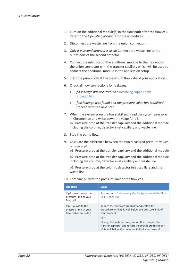
5 • Installation
Page 82 Fluorescence Detectors (VC-D50, VC-D51, VF-D50, VF-D51) Operating Manual
1. Turn on the additional module(s) in the flow path after the flow cell.Refer to the Operating Manuals for these modules.
2. Disconnect the waste line from the union connector.
3. Only if a second detector is used: Connect the waste line to theoutlet port of the second detector.
4. Connect the inlet port of the additional module to the free end ofthe union connector with the transfer capillary which will be used toconnect the additional module in the application setup.
5. Start the pump flow at the maximum flow rate of your application.
6. Check all flow connections for leakages:
¨ If a leakage has occurred: See Resolving Liquid Leaks( page 162).
¨ If no leakage was found and the pressure value has stabilized:Proceed with the next step.
7. When the system pressure has stabilized, read the system pressurein Chromeleon and write down the value for p2.p2: Pressure drop at the transfer capillary and the additional moduleincluding the column, detector inlet capillary and waste line
8. Stop the pump flow.
9. Calculate the difference between the two measured pressure values:p3 = p2 – p1.p3: Pressure drop at the transfer capillary and the additional module
p2: Pressure drop at the transfer capillary and the additional moduleincluding the column, detector inlet capillary and waste line
p1: Pressure drop at the column, detector inlet capillary and thewaste line
10. Compare p3 with the pressure limit of the flow cell.
Situation Steps
If p3 is well below thepressure limit of yourflow cell
Proceed with Determining the Backpressure of the FlowCell ( page 83).
If p3 is close to thepressure limit of yourflow cell or exceeds it
Reduce the flow rate gradually and restart theprocedure until p3 is well below the pressure limit ofyour flow cell.–or–Change the system configuration (for example, thetransfer capillary) and restart the procedure to check ifp3 is well below the pressure limit of your flow cell.
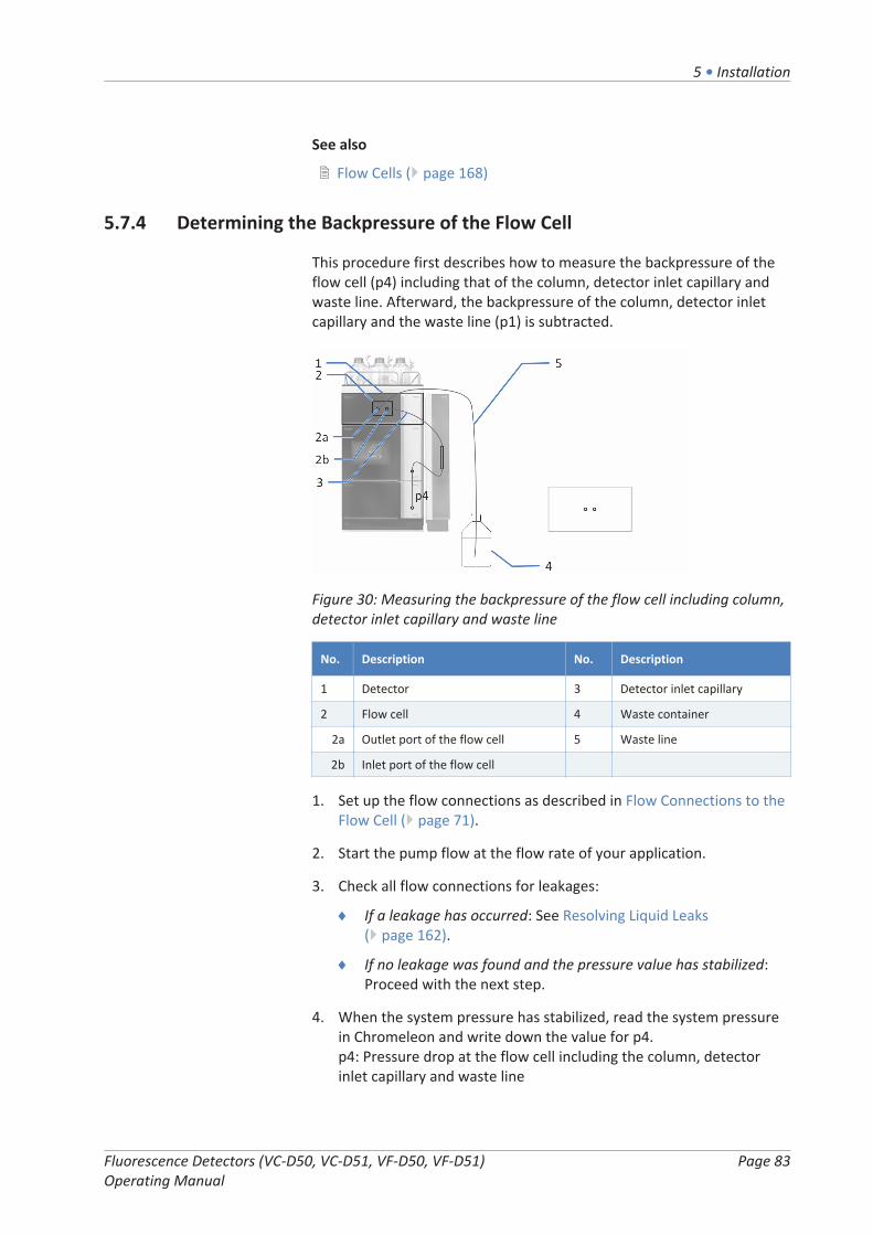
5 • Installation
Fluorescence Detectors (VC-D50, VC-D51, VF-D50, VF-D51) Operating Manual
Page 83
See also
2 Flow Cells ( page 168)
5.7.4 Determining the Backpressure of the Flow Cell
This procedure first describes how to measure the backpressure of theflow cell (p4) including that of the column, detector inlet capillary andwaste line. Afterward, the backpressure of the column, detector inletcapillary and the waste line (p1) is subtracted.
Figure 30: Measuring the backpressure of the flow cell including column,detector inlet capillary and waste line
No. Description No. Description
1 Detector 3 Detector inlet capillary
2 Flow cell 4 Waste container
2a Outlet port of the flow cell 5 Waste line
2b Inlet port of the flow cell
1. Set up the flow connections as described in Flow Connections to theFlow Cell ( page 71).
2. Start the pump flow at the flow rate of your application.
3. Check all flow connections for leakages:
¨ If a leakage has occurred: See Resolving Liquid Leaks( page 162).
¨ If no leakage was found and the pressure value has stabilized:Proceed with the next step.
4. When the system pressure has stabilized, read the system pressurein Chromeleon and write down the value for p4.p4: Pressure drop at the flow cell including the column, detectorinlet capillary and waste line

5 • Installation
Page 84 Fluorescence Detectors (VC-D50, VC-D51, VF-D50, VF-D51) Operating Manual
5. Stop the pump flow.
6. Calculate the difference between the two measured pressure values:p5 = p4 – p1.p5: Pressure drop at the flow cell
p4: Pressure drop at the flow cell including the column, detectorinlet capillary and waste line
p1: Pressure drop at the column, detector inlet capillary and thewaste line
5.7.5 Calculating the Pressure at the Inlet Port of the Flow Cell
This procedure describes how to determine the pressure at the flow cellinlet port (p6) for the intended configuration.
Figure 31: Calculating the pressure at the inlet port of the flow cell inyour used system configuration (here with second detector)
No. Description No. Description
1 Detector 5 Waste container
2 Flow cell 6 Outlet port of the seconddetector
2a Outlet port of the flow cell 7 Inlet port of the seconddetector
2b Inlet port of the flow cell 8 Second detector
3 Detector inlet capillary 9 Waste line
4 Column 10 Transfer capillary
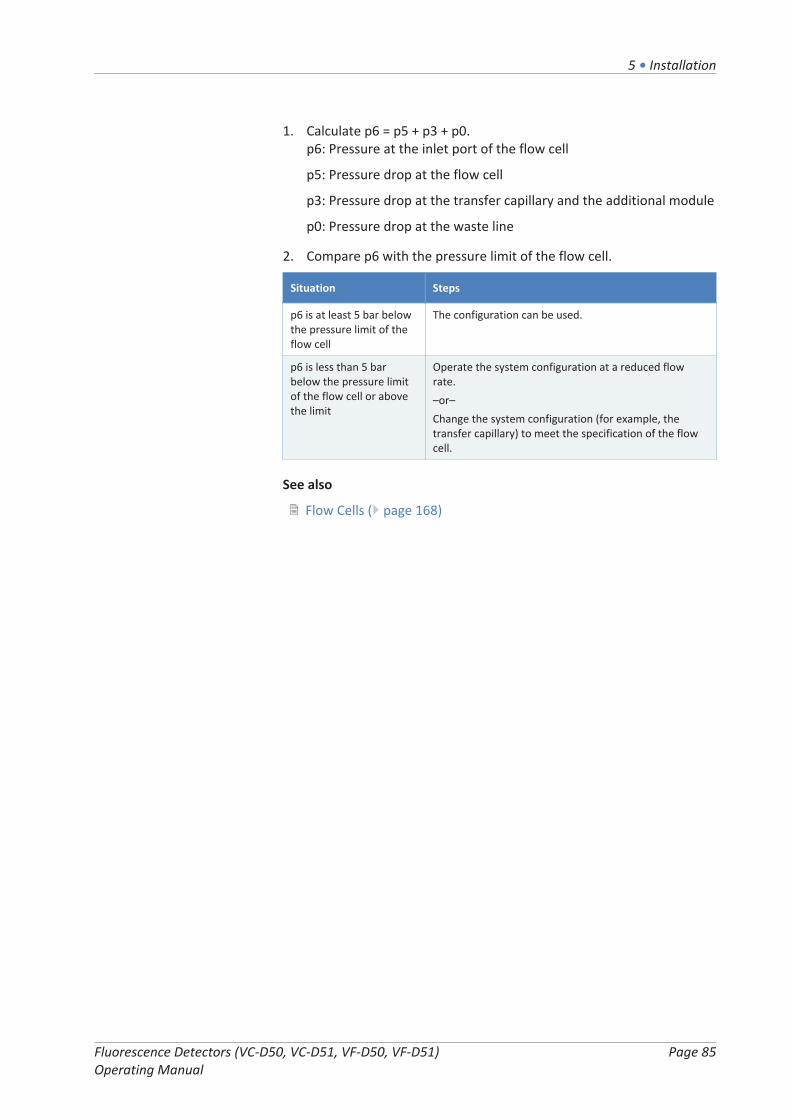
5 • Installation
Fluorescence Detectors (VC-D50, VC-D51, VF-D50, VF-D51) Operating Manual
Page 85
1. Calculate p6 = p5 + p3 + p0.p6: Pressure at the inlet port of the flow cell
p5: Pressure drop at the flow cell
p3: Pressure drop at the transfer capillary and the additional module
p0: Pressure drop at the waste line
2. Compare p6 with the pressure limit of the flow cell.
Situation Steps
p6 is at least 5 bar belowthe pressure limit of theflow cell
The configuration can be used.
p6 is less than 5 barbelow the pressure limitof the flow cell or abovethe limit
Operate the system configuration at a reduced flowrate.–or–Change the system configuration (for example, thetransfer capillary) to meet the specification of the flowcell.
See also
2 Flow Cells ( page 168)
5 • Installation
Page 86 Fluorescence Detectors (VC-D50, VC-D51, VF-D50, VF-D51) Operating Manual
5.8 Turning On the Device
TIP
Before turning on the power to a Vanquish system module for the firsttime, verify that the chromatography software is installed on the datasystem computer. When the power is turned on, the required USBdrivers are automatically found and the Windows™ operating systemcan detect the device.
To turn on the power to the device, follow these steps:
1. Check that the power button on the front left of the Vanquishsystem base (system power button) is pressed in. If the powerbutton stands out, press the power button to turn on the power onthe system base.
2. Turn on the device with its main power switch.
Turn the device off with the main power switch, when instructed to doso, for example, during maintenance. Pressing the system power buttonwill not be sufficient to turn off the power to the device completely.
See also
2 Power On/Off Control ( page 95)

5 • Installation
Fluorescence Detectors (VC-D50, VC-D51, VF-D50, VF-D51) Operating Manual
Page 87
5.9 Setting Up the Device in the SoftwareThis manual assumes that the chromatography software is alreadyinstalled on the data system computer and a valid license is available.
For more information about setting up the Vanquish system in thesoftware, refer to the Vanquish System Operating Manual.
The Help for the software that you are using provides detailedinformation about the settings on each property page.

5 • Installation
Page 88 Fluorescence Detectors (VC-D50, VC-D51, VF-D50, VF-D51) Operating Manual

6 • Operation
Fluorescence Detectors (VC-D50, VC-D51, VF-D50, VF-D51) Operating Manual
Page 89
6 OperationThis chapter describes the elements for device control, providesinformation for routine operation and for shutdown.

6 • Operation
Page 90 Fluorescence Detectors (VC-D50, VC-D51, VF-D50, VF-D51) Operating Manual
6.1 Introduction to this ChapterThe information in this chapter assumes that the initial setup of thedevice has already been completed. If this is not the case, refer to theinstructions in Installation ( page 47).
For a basic description of instrument control and automated sampleanalysis with the Chromeleon software, refer to the Vanquish SystemOperating Manual. Details on control and operation of the device areavailable in the Chromeleon Help.
Software descriptions in this manual refer to Chromeleon 7.Terminology may be different to that of other software versions.

6 • Operation
Fluorescence Detectors (VC-D50, VC-D51, VF-D50, VF-D51) Operating Manual
Page 91
6.2 Safety Guidelines for OperationWhen operating the device, pay attention to the following safetyguidelines:
Observe all warning messages and precautionary statements presentedin Safety Precautions ( page 21).
CAUTION—Hot Surfaces
Surfaces inside the device may become hot during operation. Touchinghot parts might cause burns.
Allow hot surfaces to cool down before you touch them.
NOTICE
Pay attention also to the following guidelines:
If the pump flow is interrupted, take appropriate measures to protectthe flow cell. Observe the guidelines for use of flow cells in Guidelinesfor Use of Flow Cells ( page 98).

6 • Operation
Page 92 Fluorescence Detectors (VC-D50, VC-D51, VF-D50, VF-D51) Operating Manual
6.3 Control ElementsThe device is designed to be operated mainly from a computer runningwith the chromatography software.
In addition, the following elements are available on the device:
• KeypadThe keypad buttons allow you to perform certain functions directlyfrom the device.
• Status indicatorsThe LEDs (Light Emitting Diodes) on the status indicator LED bar onthe front side of the device and the STATUS LED on the keypadprovide a quick visual check of the operational status of the device.
6.3.1 Keypad
The keypad inside the device allows you to perform certain functionsdirectly from the device. When you press a button, a short beepconfirms that the function is performed.
Figure 32: Keypad
STATUS
The STATUS LED provides a quick visual check of the operational statusof the device.
When the doors are closed, the LED bar on the front side indicates theoperational status.
For status details, see Status Indicators ( page 93).
MUTE ALARM
Beeping alerts you when the device detects a problem, for example,leakage. To turn off the beep for the current alarm, press this button.Eliminate the source for the alarm within 10 minutes. Otherwise,beeping starts again. If the device detects a different problem, beepingalerts you again immediately.

6 • Operation
Fluorescence Detectors (VC-D50, VC-D51, VF-D50, VF-D51) Operating Manual
Page 93
INIT
The INIT button allows you to perform a basic initialization bydetermining the start positions of the grating motors and the filterwheel. The LED next to the button indicates the initialization status:
LED Description
Off (dark) The detector is not initialized, or turned off.
Green, flashing The detector is initializing.
Green The detector is initialized.
If the LED turns off after initialization, verify that the flow cell is installedcorrectly and press the INIT button again.
6.3.2 Status Indicators
The status LED bar on the front side of the device and the STATUS LEDon the inside keypad provide information about the device status.
LED Bar
The LED bar provides the information when the device is closed. Whenthe device is connected in the Chromeleon software, the LED bar mayprovide less information.
LED Bar Description
Off (dark) The power to the device is turned off.
Dimmed The doors of the device are open.
Yellow, flashing slowly The power to the device is turned on, but the deviceis not connected in the Chromeleon software.
Yellow The device is connected in the Chromeleonsoftware, but the device is not initialized.
Green, flashing The device is initializing.
Green The device is initialized, but no data acquisition isrunning.
Blue, running A data acquisition is running.
Blue An injection or sequence is running.
Red A problem or error has occurred. For the relatedmessage, check the Chromeleon Audit Trail. Forremedial action, see Troubleshooting ( page 155).

6 • Operation
Page 94 Fluorescence Detectors (VC-D50, VC-D51, VF-D50, VF-D51) Operating Manual
STATUS LED
The STATUS LED on the keypad inside the device provides the followinginformation:
STATUS LED Description
Off (dark) The power to the device is turned off.
Green The device is functioning properly.
Red A problem or error has occurred. For the related message, checkthe Chromeleon Audit Trail. For remedial action, seeTroubleshooting ( page 155).

6 • Operation
Fluorescence Detectors (VC-D50, VC-D51, VF-D50, VF-D51) Operating Manual
Page 95
6.4 Power On/Off ControlThe power switch on the device is the main switch for power on/offcontrol. The main power switch is turned on during initial installation ofthe device.
For easier handling, you can use the power button on the front left ofthe Vanquish system base (system power button) for power on/off.
Observe the following:
• All modules in the Vanquish system that are connected to thesystem base via system interlink cables are turned on or offsimultaneously when the system power button is pressed.
• When the power is on, the system power button is pressed in. Whenthe power is off, the system power button stands out.
• If the main power switch on a device is off, you cannot turn on thedevice with the system power button.
• To turn off a device completely, you have to turn it off with the mainpower switch on the device. Pressing the system power button willnot be sufficient to turn off the power to the device completely.
The following sequence of events occurs when the device is powered upand the front doors are closed:
• The device runs a series of internal tests. (The test takes about30 seconds.) During these self-diagnostics, all of the maincomponents are checked.
• After the self-test, the device starts basic initialization. During thistime, the LED bar is flashing green.
• The LED bar turns green if initialization was successful.If the LED bar turns red, verify that a flow cell is properly installed,and press the INIT button on the keypad to re-initialize. The LED bar,and the LED next to the INIT button both turn green if initializationwas successful.

6 • Operation
Page 96 Fluorescence Detectors (VC-D50, VC-D51, VF-D50, VF-D51) Operating Manual
6.5 Preparing the Device for OperationThis section gives information on any additional steps that are requiredto prepare the device for operation and sample analysis.
Before Operating the Device for the First Time
Prepare the device for the first-time operation, observing the following:
NOTICE
Flush the system flow path thoroughly before operating the device forthe first time:
• When you install devices or components to the system, always flushthem to waste before connecting them in the system flow path. Toflush the Vanquish modules, follow the instructions in the VanquishSystem Operating Manual.
• When operating the device with a flow cell that was stored, the flowcell may be filled with solvent. Use solvents that are miscible withthis solvent, or use an appropriate intermediate solvent.
Before Starting Sample Analysis
Before starting an analysis:
• Check the liquid level in the solvent reservoirs. Verify that theamount of solvent is sufficient for the analysis.
• Verify that the doors of all modules in the Vanquish system areclosed.
• Observe the guidelines for use of flow cells in Guidelines for Use ofFlow Cells ( page 98).
• Make sure that the chromatography system is properly equilibrated(see further down).
System Equilibration
System equilibration should include the following operations:
• Purging the pump (all channels, including those not used for theapplication)
• Flushing the entire chromatography system with the starting solventto rinse out any solvent from a previous analysis run

6 • Operation
Fluorescence Detectors (VC-D50, VC-D51, VF-D50, VF-D51) Operating Manual
Page 97
• Warming up (or cooling down) all temperature-controlled devices inthe system to the starting temperature. Temperature-controlleddevices can be, for example
¨ Column compartment and post-column cooler
¨ Sample compartment thermostatting in the autosampler
¨ Flow cell in a fluorescence detector
¨ Evaporation tube in a charged aerosol detector
• Turning on the lamp (or lamps) in the UV/VIS detector
• Monitoring the pump pressure and pressure ripple and checkingthat the pressure is stable and the ripple within reasonable limits forthe application
• Monitoring the detector signal and checking whether the detectorsignal is stable so that the drift and signal noise are withinreasonable limits for the application
• Performing an autozero of the detector baseline
TIP The Chromeleon software supports procedures for automaticallystarting a chromatography system in the software (Smart Startup). Thestartup procedure includes the operations for system equilibration. Fordetails, refer to the Chromeleon Help.

6 • Operation
Page 98 Fluorescence Detectors (VC-D50, VC-D51, VF-D50, VF-D51) Operating Manual
6.6 Guidelines for Use of Flow Cells
NOTICE
Flow cells are sensitive to damage and contamination.
• Handle flow cells with care. See Guidelines for Handling Flow Cells( page 136).
• Observe the guidelines below when operating the detector.
Operating conditions
Observe the specified maximum pressure limit for the flow cell. See thespecifications for flow cells in Flow Cells ( page 168).
Troubleshooting flow cells
If a flow cell leaks, stop the pump flow, remove the flow cell from thedetector as quickly as possible, thoroughly remove all liquid from theflow cell opening in the detector, and replace the flow cell.
Interrupted operation
If the pump flow is interrupted, take appropriate measures to protectthe flow cell.
• If data acquisition is still running, turn data acquisition off.
• Never leave any substances, particularly any aggressive solvents, inthe flow cell without flow for a longer time.
TIP To prevent dust particles from causing damage to the detector opticsduring periods of detector inactivity, install a flow cell or reinstall theflow cell cover.
Storage
• To avoid the growth of algae, the flow cell should not be filled withpure water. Add 10% HPLC-grade isopropanol, for example.
• Close the flow cell inlet and outlet using the flow cell plugs that wereinstalled when the flow cell was shipped. Using different plugs andtightening them may destroy the flow cell.
6 • Operation
Fluorescence Detectors (VC-D50, VC-D51, VF-D50, VF-D51) Operating Manual
Page 99
6.7 Operational Modes of the DetectorThe device provides five operational modes:
• Single-channel mode
• Multi-channel mode
• Zero Order Mode
• Single spectrum scan
• FL Field Acquisition
6.7.1 Single-Channel Mode
A fluorescence detector is usually operated in single-channel mode, thatis, a single excitation/emission wavelength pair is measured over time.Other wavelength pairs and related detection parameters can be set atany time of the separation to adapt to the specifics of the analytes.Preferably this change should take place while no peak is detected. Asthis mode provides the highest possible data rates and best signal-to-noise ratio, always use the single-channel mode for very small peaks.
6.7.2 Multi-Channel Mode (VF detectors only)
In multi-channel mode, both monochromators quickly switch betweenthe selected wavelengths. A single analysis is sufficient to measureseveral channels. The detector can acquire up to four wavelength pairssimultaneously. However, note that:
• Each additional channel increases the time that the detectorrequires to set the grating positions, reduces maximum possibledata collection rate, and leads to an increased baseline noise.
• Switching permanently between the wavelengths can lead to wearin the long term. The multi-channel mode is therefore onlyrecommended for method development, but not for continuousroutine operation.
• As an alternative, you can switch the wavelengths as often asrequired between different peaks in a single data channel in theChromeleon software. In addition to the excitation and emissionwavelength, you can switch the sensitivity, the emission filter, PMTand lamp mode.

6 • Operation
Page 100 Fluorescence Detectors (VC-D50, VC-D51, VF-D50, VF-D51) Operating Manual
Setting the Multi-Channel Performance
In multi-channel mode, you can select a measuring performance (multi-channel performance) to determine whether the measurement isperformed faster, but with more noise, or whether minimum noise isrequired, which means a longer measuring time and lower datacollection rate. The possible values are: UltraFast, Fast, Standard,LowNoise, UltraLowNoise.
Response time and data collection rate for multi-channel mode aredetermined automatically on the basis of the selected multi channelperformance and the selected parameters, and adjusted each timewavelengths are switched during the measurement.
Using multiple channels in the Chromeleon software
Use the Instrument Method Wizard (Advanced mode) to define theparameter settings for all channels and the multi-channel performance.
See also
2 Determining the Optimum Excitation and Emission Wavelength( page 107)
6.7.3 Zero Order Mode
In Zero Order Mode, the grating of the emission monochromator reflectsthe entire emission spectrum of the sample onto the PMT, rather thanonly a single wavelength. The excitation monochromator is set to asingle wavelength as usual.
Use this mode during method development, if you do not know theretention times and emission wavelengths of the various substances inyour sample. As the entire range of emission wavelengths is acquired,you can determine the retention times of all substances in a single run,as long as the substances can be excited at the selected excitationwavelength.
TIP
Use the filter wheel setting (VF detectors only) to cut off undesiredwavelengths. For example, set the filter wheel setting to 370 nm torestrict the emission wavelength range to wavelengths above the filterwavelength.
The Zero Order Mode is also suitable for samples that emit light in anexceptionally broad band. In this case, the measured intensity is higherin Zero Order Mode than under normal operation where most of theemitted light is discarded by the emission monochromator. This mightallow you to achieve a better limit of detection.

6 • Operation
Fluorescence Detectors (VC-D50, VC-D51, VF-D50, VF-D51) Operating Manual
Page 101
For an example of method development using the Zero Order Mode,refer to the Fluorescence Method Development Handbook.
TIP
To activate the Zero Order Mode in the Chromeleon software, set theEmWavelength property to ZeroOrder.
See also
2 Filter Wheel (VF detectors only) ( page 112)
6.7.4 Single Spectrum Scan
During a Single Spectrum Scan, the excitation monochromator oremission monochromator (or both simultaneously) moves over asettable wavelength range, while the intensity of the fluorescencesignals is measured and recorded continuously for each wavelength. Thisallows you, for example, to record spectra for determining the optimumemission and excitation wavelengths. There are three different scanmodes: excitation scan, emission scan, and synchronous scan.
To achieve stable conditions in the flow cell, it is recommended stoppingthe pump flow or have the pump deliver at a very low flow rate. If thescan can be completed during the elution of a peak and the scan issignificantly faster than the full width at half maximum of the peak, thepump flow can be kept constant. For further information, refer to theChromeleon Help.
Recording a baseline spectrum
A baseline spectrum with the same parameters can be recorded for allscan modes. The baseline spectrum is stored in the Chromeleonsoftware and automatically subtracted from the recorded spectra. Theresult is a difference spectrum, that is, the autofluorescence of the usedsolvent is eliminated. Note that Chromeleon issues a warning if thebaseline spectrum is missing.
Whenever the parameters for a scan change, the background spectrumis automatically deleted and a new spectrum must be recorded. You candelete a baseline spectrum any time by using the ClearBaseLinecommand.
Excitation Scan
The wavelength on the emission monochromator is kept constant, whilethe excitation monochromator scans a wavelength range. The result isan excitation spectrum of the sample.

6 • Operation
Page 102 Fluorescence Detectors (VC-D50, VC-D51, VF-D50, VF-D51) Operating Manual
Emission Scan
The wavelength on the excitation monochromator is kept constant,while the emission monochromator scans a wavelength range. Theresult is an emission spectrum of the sample.
Synchronous Scan
A user-defined excitation wavelength range is scanned, while theemission wavelength is scanned synchronously with a fixed user-definedoffset. This allows you to determine a suitable wavelength pair for initialexperiments. However, the optimum excitation and emissionwavelengths must be determined by using separate excitation scans andemission scans.
To perform a single spectrum scan
For information on spectrum scans as well as instrument methodexamples, refer to the Chromeleon Help.
CAUTION
• During the scan process, no other commands can be sent to thefluorescence detector.
• The duration of the scan process depends on the range to bescanned and the selected scan speed.
• Before each scan, select a detector sensitivity, using theScanSensitivity parameter. If the detector sensitivity is set too high,no spectra will be saved and a message appears in the audit trail.
• Artefacts may occur when scanning near extreme changes in thespectrum (which frequently occur near the excitation wavelength),for example, when scanning the Raman emission spectrum of waternear the excitation of 350 nm. In this case, select a greater distancebetween the wavelength scan range and the edge (greater than theminimum of 20 nm). For the Raman emission scan, for example,select a start wavelength of 385 nm.
6.7.5 FL Field Acquisition
FL Field Acquisition can help you in determining retention times andemission maxima. As opposed to single spectrum scans, where theselected spectral range is scanned once, the spectral range is scannedcontinuously, resulting in a spectral field similar to a 3D field of a diodearray detector. Available scan modes are:
• Excitation
• Emission• Synchronous

6 • Operation
Fluorescence Detectors (VC-D50, VC-D51, VF-D50, VF-D51) Operating Manual
Page 103
It is not possible to simultaneously acquire chromatograms during FLField Acquisition .
FL Field Acquisition is available in the Chromeleon 7 software only. Use a3D data field to determine the retention times and optimum emission orexcitation wavelengths. For more information about 3D data fields, referto the Chromeleon Help.
For an example of method development using the FL Field Acquisitionsynchronous scan mode, refer to the Fluorescence MethodDevelopment Handbook.

6 • Operation
Page 104 Fluorescence Detectors (VC-D50, VC-D51, VF-D50, VF-D51) Operating Manual
6.8 Important Operating ParametersThe commands and parameters described in the table should beconsidered for simple routine operation of the device. You can usuallyaccess these parameters from the Chromeleon user interface.
If a parameter listed below is not available in the Chromeleon software,consider updating the firmware and Chromeleon version.
TIP The Instrument Method Wizard provides different parameter viewmodes. Depending on the parameters to be set, you can select thedesired view mode (for example, Easy or Advanced).
For more information, refer to Chromeleon Help and documents.
Parameter Description
Emission signalparameters
The Emission signal channels (Emission_x) are the signalchannels for recording an excitation/emission wavelengthpair. Signal parameters are settable for each signal channelseparately. For guidelines on selecting the signalparameters, see Optimizing the Performance of the Device( page 106).
Excitation wavelength Sets the excitation wavelength in nm. Select the excitationwavelength at the absorption maximum of the samplecomponent to be analyzed.
Emission wavelength Sets the emission wavelength in nm. The emissionwavelength must be at least 20 nm above the excitationwavelength.ZeroOrder: The grating of the emission monochromator isset to the position of zero order. For details, see Zero OrderMode ( page 100).
Sensitivity Sets the detector sensitivity, see Sensitivity (DetectorSensitivity) ( page 108).
Data collection rate Sets the number of data points per second (Hz) that theChromeleon software collects from the detector and storesas raw data.For further information, see Data Collection Rate andResponse Time (Single-Channel Mode) ( page 113).
Lamp mode Sets the mode of operation for the xenon flash lamp. Ahigher frequency of flashes improves the baseline noise andthus improves sensitivity. A lower flash frequency extendsthe lifetime of the lamp.For details, see Lamp Mode ( page 115).
Effective lamp age Provides information about the lamp operating hours tohelp you in estimating the remaining lamp lifetime. Forfurther information, see Monitoring the Lamp Age( page 131).

6 • Operation
Fluorescence Detectors (VC-D50, VC-D51, VF-D50, VF-D51) Operating Manual
Page 105
Parameter Description
Initialize Performs a basic calibration by determining the startposition of the grating motors and filter wheel. Execute ifthe message "Not initialized" appears in the ChromeleonAudit Trail after the detector is turned on.
Leak detection Leak detection is enabled as a standard when the device isshipped (Leak Sensor Mode = Enabled). This is thepreferred setting.

6 • Operation
Page 106 Fluorescence Detectors (VC-D50, VC-D51, VF-D50, VF-D51) Operating Manual
6.9 Optimizing the Performance of the DeviceThis section provides information for best performance of the deviceand gives hints on what you can do to optimize the performance further.
Fluorescence Method Development Handbook
Basic information about how to optimize the detector performance canbe obtained from the following sections of this Operating Manual. Inaddition, the Fluorescence Method Development Handbook that isshipped with the detector guides you through the different methoddevelopment and optimization steps, recommends the most suitableprocedures, and explains optical effects that might be observed.
See also
2 Important Operating Parameters ( page 104)
6.9.1 General Guidelines
Consider the following guidelines for optimization of the deviceperformance:
• Make sure that the grade of the solvent is compatible with thespecific application. In many cases, selecting fluorescence-gradesolvents should serve the need for low background fluorescence.However, your normal HPLC-grade solvents may also be suitable.
• In general, fluorescence detection has different requirements forsolvent quality compared to UV detection. Fluorescing contaminantsor particles may cause background fluorescence and stray light, andthus increase noise and reduce the dynamic range of the detector.
• Experience shows that the solvent suitability for an applicationstrongly depends on the selected detection wavelengths and therequired detection performance limits. For information andguidance on how to test the background fluorescence on yourmobile phase, refer to the Fluorescence Method DevelopmentHandbook.
• Degas the solvent.
• Consider the influences of the parameters on the detection.
• Keep the device doors closed during operation to avoid exposure ofthe flow cell to thermal changes in the environment that may lead toa baseline drift.
Monitor the lamp age (see Monitoring the Lamp Age ( page 131)) andschedule appropriate maintenance intervals.

6 • Operation
Fluorescence Detectors (VC-D50, VC-D51, VF-D50, VF-D51) Operating Manual
Page 107
• Observe the general guidelines and recommendations on the use ofsolvents and additives in the chromatography system. Refer to Useof Solvents and Additives in the Vanquish System Operating Manual.
See also
2 Overview of Optimization Parameters ( page 107)
2 Monitoring the Lamp Age ( page 131)
6.9.2 Overview of Optimization Parameters
The following table serves as an overview of parameters that influencedetector performance and indicates the performance characteristicsaffected. The sections below offer guidelines for selecting theparameters.
Parameter Affects
Excitation wavelength,emission wavelength
Fluorescence intensity, limit of detection,selectivity
Sensitivity Baseline noise, max. fluorescence intensity
Filter wheel setting Baseline noise, permitted wavelength range foremission
PMT Emission wavelength range (and thereforeexcitation wavelength range)
Response time Baseline noise, peak width, peak height
Data collection rate Peak resolution, disk space, possibly baseline noise
Flow cell temperature Fluorescence intensity, reproducibility
Lamp mode Lamp lifetime, baseline noise, maximum datacollection rate
Baseline behavior Course of the baseline after switching thewavelength, sensitivity, filter wheel, or PMT.
6.9.3 Determining the Optimum Excitation and Emission Wavelength
The most important parameters that need to be optimized are theexcitation and emission wavelength. Note the following key criteria fordetermining the wavelength for an analysis:
• Preferably, select an excitation wavelength on the absorptionmaximum of the sample components.
• Avoid the wavelength range where the solvents absorb (forexample, below 220 nm for methanol and below 210 nm foracetonitrile). The excitation wavelength should always be selected

6 • Operation
Page 108 Fluorescence Detectors (VC-D50, VC-D51, VF-D50, VF-D51) Operating Manual
above the UV cutoff of the solvent. For information about the UVcutoff wavelengths of solvents, see UV Cutoff Wavelengths ofSolvents ( page 180).
• Select an emission wavelength that is at least 20 nm above theexcitation wavelength.
TIP Chromeleon 7 supports FL Field Acquisition for the fluorescencedetector, which facilitates determining the retention times andabsorption maxima.
For further information about selecting the optimum wavelengths, referto the Fluorescence Method Development Handbook that is shippedwith the detector.
Wavelength Switching in the Chromeleon Software
Thermo Fisher Scientific recommends using the single-channel mode torecord data by switching the wavelengths in-between the detectedpeaks of the various sample components, rather than to simultaneouslymeasure all interesting wavelengths in multi-channel mode.
Use the Instrument Method Wizard to set the start wavelengths for onechannel. After completion of the wizard, open the method in theInstrument Method Editor. In the Module View for the detector, on theTimetable tab page, you can define the times for switching thewavelengths and other parameters.
For details, also see the Chromeleon Help.
6.9.4 Sensitivity (Detector Sensitivity)
The Sensitivity setting is used to optimize the signal-to-noise ratio in achromatogram. Depending on the intensity of the fluorescence, it maybe necessary to adjust the sensitivity several times during an analysis. Tofind the best sensitivity, it is required to determine the maximumemission intensities in a separate sample run.
Sensitivity Setting and Autoranging
A PMT (or two PMTs) measures the intensity of the emission light afterthe emission monochromator. The sensitivity of the PMT can beadjusted in 8 stages (1 to 8) with the Sensitivity setting. With each stage,the sensitivity of the PMTs increases by approximately a factor 2. If apeak with sensitivity = 5 is 15 million counts high, for example, the peakheight increases to 30 million counts when the sensitivity = 6.
• If the selected sensitivity is too small, the peak height is reduced andthe signal-to-noise ratio is not optimal (see figure, Sensitivity = 1).

6 • Operation
Fluorescence Detectors (VC-D50, VC-D51, VF-D50, VF-D51) Operating Manual
Page 109
• If the selected sensitivity is too large, the PMT signal is saturated. Inthis case, the detector automatically reduces the sensitivity. Markersappear in the chromatogram at the beginning and at the end of thesaturation (see figure, Sensitivity = 8). If the detector is not saturatedany more, the Sensitivity setting before saturation is restored.
TIP When the sensitivity was automatically reduced or when the initialvalue was restored, the Chromeleon Audit Trail shows a warning withthe new sensitivity value after the adjustment.
Figure 33: Effects of the Sensitivity setting
With Vanquish fluorescence detectors, the intensity of the emission light(measured by the PMT) is normalized with the intensity of excitationlight through the sample (measured by the reference sensor). Therefore,the values (counts) that the emission channel displays cannot be usedfor optimizing the sensitivity. In the figure, the PMT is saturated at63 million counts. However, under different measuring conditions, thePMT may be saturated at a value of 100 million counts, for example.
Therefore, use the MaxPMTSaturation parameter to optimize thesensitivity for each peak as described below. This parametercontinuously records the maximum PMT saturation since the lastClearMaxPMTSaturation command. The result is reported in percent ofthe maximum permitted PMT saturation.

6 • Operation
Page 110 Fluorescence Detectors (VC-D50, VC-D51, VF-D50, VF-D51) Operating Manual
Determining the optimum sensitivity
Determine the optimum sensitivity in a separate sample run after youhave determined the optimum wavelengths as described below.
• Use a sample (standard) with the maximum expected concentrationof the analytes.
• Select a sensitivity at which a saturation is not expected (forexample, 1 or 2).
• If the peak heights of the individual peaks in a chromatogram differ,you can improve the signal-to-noise ratio of the smaller peaks byswitching the sensitivity during the run and between the peaks withthe help of a timetable.
• Always use the same PMT setting for determining the sensitivity thatis used for the analysis.
An instrument method example is available in the Chromeleon Help.
Follow these steps
1. Open the method you want to optimize in the Script Editor. Therequired commands must be added to the method manually.
2. Add a ClearMaxPMTSaturation command at the beginning of therun.
3. Add a Log command for the MaxPMTSaturation property after thepeak maximum of an expected peak (or group of peaks) to log themaximum saturation value at this time in the Audit Trail (see figurebelow).
4. Add a ClearMaxPMTSaturation command shortly after, before thenext peak elutes, to reset the MaxPMTSaturation value to zero (seefigure below).

6 • Operation
Fluorescence Detectors (VC-D50, VC-D51, VF-D50, VF-D51) Operating Manual
Page 111
Figure 34: MaxPMTSaturation parameter monitoring
5. Repeat steps 3 through 4 for all peaks.
6. Run a sample and read out the MaxPMTSaturation values in theChromeleon software and evaluate the results:
Value What you should do…
< 30% Increase the Sensitivity. The following is a rough guideline:< 30 %: by one stage< 15 %: by two stagesThen repeat the optimization, starting with step 1.
30% - 80% The Sensitivity value is optimal.
80% - 99% The Sensitivity should be reduced by one stage to prevent unexpectedsaturation when concentration varies.
≥ 100% Reduce the Sensitivity by at least one stage. In most cases, the detectorhas reduced Sensitivity automatically ("autoranging"). Check the AuditTrail for the smallest Sensitivity value after the autoranging and repeatthe optimization by using this value, starting with step 1.
If you do not know the expected concentrations of the analytes, reducethe sensitivity even at smaller values of MaxPMTSaturation.
TIP
• The maximum saturation indicated by MaxPMTSaturation alwaysrefers to the signals of both PMTs at the parameter settings for allchannels.
• You can completely turn off fluorescence detection by setting thesensitivity to Off. This may be required, for example, if you want torecord the incoming signal from a UV detector for a sample of highconcentration, or to suppress an extremely high peak that is not ofinterest for you but triggers an automatic adjustment of thesensitivity.

6 • Operation
Page 112 Fluorescence Detectors (VC-D50, VC-D51, VF-D50, VF-D51) Operating Manual
6.9.5 Filter Wheel (VF detectors only)
To prevent stray light from reaching the PMT, additional optical edgefilters are installed on a filter wheel in the light path between the flowcell and the emission monochromator. This reduces direct scattering oflight from the light source. In addition, a grating monochromator letsunwanted fractions (the half, one third, ...) of a selected wavelengthpass. If the monochromator is set to 500 nm, for example, second-orderlight at 250 nm from the sample may reach the PMT. The filters alsoeliminate this higher-order stray light.
Ideally, these filters can be passed by wavelengths above their cut-offwavelength, while light with a smaller wavelength than the cut-offwavelength is blocked. In practice, there is a transition area where thetransmission of the light increases from the lower wavelengths near therange where the light is cut off to the higher wavelengths near the rangewhere the light passes. At the cut-off wavelength, the filters let 50% ofthe light pass. The figure shows the transmission behavior of the 280 nmfilter as an example.
Figure 35: Transmission behavior of the 280 nm filter
The filter wheel setting can be selected automatically or manually:
• If the filter wheel mode is set to Auto, the detector automaticallyselects a filter wheel position. It selects the first filter with a cut-offwavelength below the selected emission wavelength. This mode isselected by default and provides best results for most applications.
• You can manually select the filter wavelength (that is, the cut-offwavelength). Available filters are 280 nm, 370 nm, 435 nm or530 nm. In special situations (for example, if the emission
6 • Operation
Fluorescence Detectors (VC-D50, VC-D51, VF-D50, VF-D51) Operating Manual
Page 113
wavelength is near the cut-off wavelength of a filter), setting thefilter manually may provide better results than the Auto setting.Note the following:
¨ The selected emission wavelength must not be more than 15 nmbelow the filter wavelength.
¨ If you select Open, the filter wheel remains in an open position.Use this setting if you want to measure with an emissionwavelength between 220 nm and 280 nm.
¨ Manually select the filter wheel position, for example, incombination with the Zero Order Mode . The emissionmonochromator opens and the emitted light is measured overthe entire wavelength range. Use the cut-off filter to suppresslight below the wavelength range you are interested in. Notethat this setting usually requires a lower sensitivity setting dueto the stray light and auto fluorescence of the eluent (the entirespectral range is recorded).
For further information about selecting the filter wheel setting, refer tothe Fluorescence Method Development Handbook that is shipped withthe device.
6.9.6 PMT (only if second PMT is installed)
Detectors can be equipped with a second PMT for the near-infraredregion (up to 900 nm). If the PMT setting is set to Auto, the detectorselects the suitable PMT for each measurement. As an alternative, youcan manually select which PMT should be used. Use PMT1 formeasurements in the UV/VIS region. Use PMT2 for measurements in theinfrared region.
TIP Always use the same PMT setting for calibration and quantification.A calibration performed with PMT1 may not be valid for measurementswith PMT2.
6.9.7 Data Collection Rate and Response Time (Single-Channel Mode)
The Chromeleon software automatically calculates the best responsetime, based on the value you enter for the data collection rate in theInstrument Method Wizard. Note the guidelines below for selecting thedata collection rate. If you want to select a different response time, thissection also provides a few guidelines.
6 • Operation
Page 114 Fluorescence Detectors (VC-D50, VC-D51, VF-D50, VF-D51) Operating Manual
TIP In Multi-Channel mode, the response time and data collection rateare always determined automatically. You can influence theseparameters by selecting a different multi-channel performance.
Data Collection Rate
The data collection rate is the number of data points per second (Hz)that the Chromeleon software collects from the detector and stores asraw data.
When you select a data collection rate, observe the following guidelines:
• In general, each peak should be defined by at least 20 data points.For chromatograms with co-eluting peaks or low signal-to-noiseratios, 40 data points per peak are recommended.
• If the data collection rate is too low, the start points, maxima, andend points of peaks will not be determined accurately.
• If the data collection rate is too high, data files may need more diskspace and post-run analyses may require more processing time.
• If all peaks are relatively wide, select a lower data collection rate (forexample, 1.0 Hz). This saves disk space and allows for a faster displayof data in the Chromeleon software.
• If any peaks of interest are less than a few seconds, select a higherdata collection rate (10.0 Hz, for example).
• The selected lamp mode also has an effect on the maximum datacollection rate.
Response Time
The response time is a measure of how quickly the detector responds toa change in signal.
• Select a response that is about 1/3 of the peak width at half-heightof the narrowest peak of interest. A longer response time allowsmore averaging of the signal and results in less short-term noise, andthus improves the signal-to-noise ratio.
• However, if the selected response time is too long, this can result inreduced peak heights and asymmetrical peak shapes. Peaks thatelute shortly after each other may not be separated properly. Whenset correctly, the response time significantly reduces baseline noise,but reduces peak height only slightly.

6 • Operation
Fluorescence Detectors (VC-D50, VC-D51, VF-D50, VF-D51) Operating Manual
Page 115
TIP For best possible combinations of data collection rate, response timeand peak width, enable the Link data collection parameters check box inthe detector settings of the Chromeleon Instrument Method Wizard orInstrument Method Editor.
See also
2 Lamp Mode ( page 115)
6.9.8 Flow Cell Temperature
The temperature of a sample influences its fluorescence. Thus, aproblem with fluorescence detection is that the results can strongly beinfluenced by fluctuations in ambient temperature. Vanquishfluorescence detectors allow you to heat the flow cell and thus keeptemperatures inside the flow cell at a constant level, even if ambienttemperatures change.
In most analytes, the fluorescence of a sample decreases as temperatureincreases. Therefore, the temperature must not be selected too high.However, it must be above the temperature inside the detector optics,which is influenced by the ambient temperature. Therefore, select atemperature that is roughly 15°C above the expected ambienttemperature.
Example: The expected maximum temperature in the laboratory is 27°C(80.6 F). Set the flow cell temperature to 42°C (107.6 F).
TIP Thermo Fisher Scientific recommends always recording theFLD_FlowCell signal channel. If a problem occurs, the temperaturechannel can provide helpful information to identify and eliminate thesource for the problem.
6.9.9 Lamp Mode
The detector offers three different flash frequencies for the xenon flashlamp. Selecting a different lamp mode during phases when no peaks ofinterest elute can extend the lamp lifetime.
When calculating the lamp lifetime, only the time when the lamp flashesis taken into account. This roughly corresponds to the acquisition time.

6 • Operation
Page 116 Fluorescence Detectors (VC-D50, VC-D51, VF-D50, VF-D51) Operating Manual
Extending the lamp lifetime
To extend the lamp lifetime, you can do the following:
• Turn off the lamp by stopping data acquisition if you are notinterested in the baseline. It is not generally required that the lampremains turned on during the entire chromatographic separation.
• Change the lamp mode during a chromatographic run, for example,from LongLife mode (between the peaks) to Standard or HighPowermode (for the interesting peaks). This extends the lamp lifetime,without any loss in sensitivity in the important areas.Use the Instrument Method Wizard to set the basic lamp mode.After completion of the wizard, open the method in the InstrumentMethod Editor. In the Module View for the detector, on theTimetable tab page, you can define the times for switching the lampmode and other parameters.
For an example of smart use of the xenon flash lamp modes, refer to theFluorescence Method Development Handbook .
HighPower Mode
The lamp flashes at the highest frequency of 300 Hz. The sensitivity isroughly twice the sensitivity in Standard mode. The expected lifetime ofthe lamp is approximately 1300 hours.
This mode is recommended for applications that require highestsensitivity.
Standard Mode
The lamp flashes at a medium frequency of 100 Hz. The expectedlifetime of the lamp is approximately 4000 hours. This mode supportsdata collection rates up to 100 Hz.
This mode is recommended for applications that require a highsensitivity.
LongLife Mode
The lamp flashes at a lower frequency of 20 Hz. When the lamp isoperated in this mode, the lamp lifetime is approximately four times thelifetime in Standard mode. The expected lifetime of the lamp isapproximately 16000 hours. However, note that signal-to-noise ratio isreduced to roughly the half compared to Standard mode. This modeonly supports data collection rates up to 20 Hz.
This mode is recommended for regions of the chromatogram whensignal-to-noise is less important, for example:
• when no peaks of interest elute
• during the wash and re-equilibration phase
6 • Operation
Fluorescence Detectors (VC-D50, VC-D51, VF-D50, VF-D51) Operating Manual
Page 117
6.9.10 Baseline Behavior
If wavelengths are switched or the sensitivity, filter wheel, or PMTsetting are changed during the method, the chromatogram may showbaseline jumps because of the background fluorescence at the newwavelength setting. Three baseline behavior mode settings define howthe baseline behaves in these cases:
• Zero: sets the baseline to zero
• Append: appends the baseline to the previous signal
• Free: lets the baseline "jump" to the current absolute value
TIP You can perform Autozero command (automatic null balancing) anytime, that is, the intensity measured at the time of the autozero issubtracted from any intensities measured thereafter. Always select atime for null balancing at which no sample flows through the flow cell.The values are stored and can be reset using the ClearAutozerocommand.

6 • Operation
Page 118 Fluorescence Detectors (VC-D50, VC-D51, VF-D50, VF-D51) Operating Manual
6.10 Shutting Down the DeviceIf the device will not be operated for some time, follow the instructionsin this section to shut down the device.
TIP The Chromeleon software provides procedures for automaticallypreparing the chromatography system for shutdown. The proceduresinclude, for example, operations for reducing the flow rate, reducing thetemperature in temperature-controlled devices, and turning off thedetector lamps. For information about Smart Shutdown and SmartStandby, refer to the Chromeleon Help.
6.10.1 Short-Term Shutdown (Interruption of Operation)
To interrupt operation of the device for a short period (short-termshutdown), for example, overnight, observe these guidelines for theVanquish system modules, as required by your system arrangement:
• For your Vanquish detector, note the following:
Detector Type Description
Charged aerosoldetector
Check that sufficient gas is available to continue gas flowingthrough the detector. This is to prevent any build-up ofresidue from solvents or analytes. Gas must be flowing whenpump flow is delivered to the detector.
UV/VIS detectors The lamp(s) in the detector can remain turned on.Variable wavelength detector and VH-D10 diode arraydetector only: The shutter can be moved to a closed positionfor protection of the flow cell.
Fluorescencedetector
Turn off temperature control for the flow cell.
• Apply a flow of 0.05 mL/min and have the pump deliver anappropriate solvent.Check the lower pressure limit for the pump and adapt the value ifnecessary. If the pressure falls below the lower limit, the pump stopsthe flow.
• Set the injection valve in the autosampler to the Inject position.
• Make sure that the temperature of the column does not exceed40 °C.
• When resuming operation, let the flow equilibrate and verify thatthe operating parameters for the other system modules are set asrequired before proceeding.

6 • Operation
Fluorescence Detectors (VC-D50, VC-D51, VF-D50, VF-D51) Operating Manual
Page 119
6.10.2 Long-Term Shutdown
Shutting Down the Device
To interrupt operation for a longer period, follow the instructions below.
TIP Shutting down the device affects the operation of the system. Whenshutting down the device, also observe the shutting down instructionsfor the other Vanquish system modules and take appropriate action(refer to the Operating Manuals for the modules).
1. Stop the pump flow.
2. Remove the column.
3. Connect the free ends of the column compartment capillaries usinga union connector (for example, the Viper union from the systemship kit) and restart the pump flow.
4. Flush the flow cell with an appropriate solvent (minimum HPLC-grade). Observe the following:
TIP With a Vanquish Core system that has been modified for usingnormal-phase compatible solvents and additives, see the informationabout the flushing liquid in the Considerations with Normal-PhaseCompatible Solvents and Additives section in Operating Manual for thepump.
Situation after Shutdown If no additive is used If an additive is used
Device and flow cellremain in the laboratoryafter shutdown
Flush the system, forexample with methanol.100% acetonitrile shouldnot be used.
Flush the system withseveral volumes ofmethanol and water(50:50) (for example,1.0 mL/min for10 minutes with thestandard system) toprevent salt buildup in thefluidics. If the solvents inthe flow cell are notmiscible with water, usean appropriateintermediate solvent.

6 • Operation
Page 120 Fluorescence Detectors (VC-D50, VC-D51, VF-D50, VF-D51) Operating Manual
Situation after Shutdown If no additive is used If an additive is used
Device and flow cell shallbe transported or shippedafter shutdown
Flush the system withisopropanol.
Flush the system first withseveral volumes ofmethanol and water(50:50) (for example,1.0 mL/min for10 minutes with thestandard system) toprevent salt buildup in thefluidics. If the solvents inthe flow cell are notmiscible with water, usean appropriateintermediate solvent.Afterward, flush thesystem with isopropanol.
NOTICE
Residual samples, impurities from the column or buffers with high saltconcentrations can deposit in the flow cell. This can lead to damage ofthe flow cell. In addition, solvents containing acid can damage the flowcell.
• Always flush the flow cell with an appropriate solvent beforeinterrupting operation.
• Fill the flow cell with pure isopropanol using the flushing andinjection kit.
• The flow cell should not be filled with pure water to avoid thegrowth of algae. If you want to fill the flow cell with water, you needto add 10% HPLC-grade isopropanol.
5. Turn off the pump flow to the device. Wait until the system pressureis down to zero before you continue the shutdown of the device.
6. Disconnect the capillaries from the flow cell inlet and outlet.
7. After removing the flow connections, protect the flow cell inlet andoutlet ports with the plugs supplied with the flow cell. Protect theinlet capillaries with caps.
8. The step depends as follows:
Situation Steps
Device and all other system modulesremain in the system stack and are to beturned off
Turn off the system with the systempower button on the system base.

6 • Operation
Fluorescence Detectors (VC-D50, VC-D51, VF-D50, VF-D51) Operating Manual
Page 121
Situation Steps
Device shall be transported or shippedafter shutdown
If one of the modules shall be removedfrom the system stack, turn off allsystem modules with their main powerswitch. Pressing the system powerbutton will not be sufficient to turn offthe power to the devices completely.Follow the instructions in Transporting orShipping the Device ( page 146).
TIP To prevent dust particles from causing damage to the detector opticsduring periods of detector inactivity, install a flow cell or reinstall theflow cell cover.
See also
2 Connecting the Inlet Capillary ( page 72)
2 Connecting the Detector Waste Line ( page 75)
6.10.3 Restart after Long-Term Shutdown
To restart the device after a long-term shutdown, follow these steps:
1. Prepare and restart the other modules in the Vanquish system,following the instructions in the Operating Manuals for the modules.Pay special attention to the Preparing the Module for Operationsection.
2. Flush the components in the flow path before the flow cell beforeyou connect the flow cell to the system flow path.
3. Connect the inlet capillary to the flow cell inlet and the waste line tothe flow cell outlet.
4. Turn on the device. Observe the following:
Situation Action
If the device remained in the systemstack and all system modules wereturned off.
Turn on the system with the systempower button on the system base.
If the device is restarted after transport. Turn on the device with the main powerswitch.
5. Before starting an analysis, let the detector equilibrate and be surethat it is ready for operation.

6 • Operation
Page 122 Fluorescence Detectors (VC-D50, VC-D51, VF-D50, VF-D51) Operating Manual

7 • Maintenance and Service
Fluorescence Detectors (VC-D50, VC-D51, VF-D50, VF-D51) Operating Manual
Page 123
7 Maintenance andServiceThis chapter describes the routine maintenance and the serviceprocedures that the user may perform.

7 • Maintenance and Service
Page 124 Fluorescence Detectors (VC-D50, VC-D51, VF-D50, VF-D51) Operating Manual
7.1 Introduction to Maintenance and ServiceThis chapter describes the routine maintenance and service and repairprocedures that the user may perform.
Additional maintenance or service procedures must be performed onlyby service personnel certified by Thermo Fisher Scientific (for brevity,referred to as Thermo Fisher Scientific service personnel).
The device is designed for easy maintenance and service. The user-serviceable parts of the device can be accessed from the front. If notstated otherwise, the maintenance procedures do not require that youremove the device from the system.
The maintenance procedures do not require that you remove the doors.However, it is possible to remove a door if this should ever be requiredfor a specific reason or procedure. If you need to remove a door, followthe related steps in Replacing the Doors ( page 144).
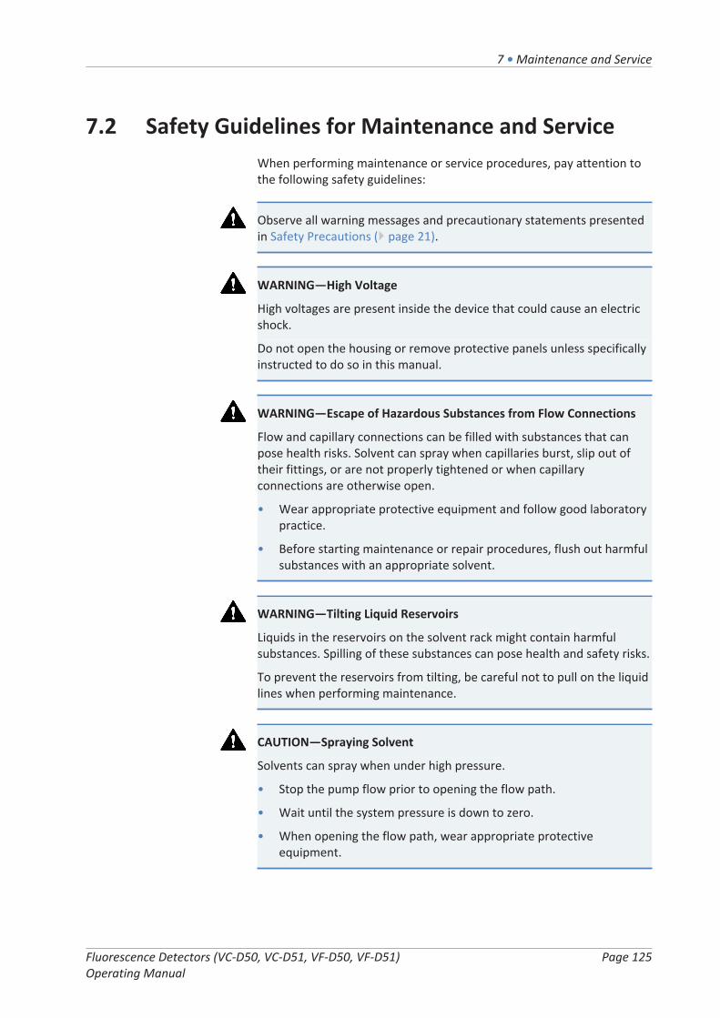
7 • Maintenance and Service
Fluorescence Detectors (VC-D50, VC-D51, VF-D50, VF-D51) Operating Manual
Page 125
7.2 Safety Guidelines for Maintenance and ServiceWhen performing maintenance or service procedures, pay attention tothe following safety guidelines:
Observe all warning messages and precautionary statements presentedin Safety Precautions ( page 21).
WARNING—High Voltage
High voltages are present inside the device that could cause an electricshock.
Do not open the housing or remove protective panels unless specificallyinstructed to do so in this manual.
WARNING—Escape of Hazardous Substances from Flow Connections
Flow and capillary connections can be filled with substances that canpose health risks. Solvent can spray when capillaries burst, slip out oftheir fittings, or are not properly tightened or when capillaryconnections are otherwise open.
• Wear appropriate protective equipment and follow good laboratorypractice.
• Before starting maintenance or repair procedures, flush out harmfulsubstances with an appropriate solvent.
WARNING—Tilting Liquid Reservoirs
Liquids in the reservoirs on the solvent rack might contain harmfulsubstances. Spilling of these substances can pose health and safety risks.
To prevent the reservoirs from tilting, be careful not to pull on the liquidlines when performing maintenance.
CAUTION—Spraying Solvent
Solvents can spray when under high pressure.
• Stop the pump flow prior to opening the flow path.
• Wait until the system pressure is down to zero.
• When opening the flow path, wear appropriate protectiveequipment.
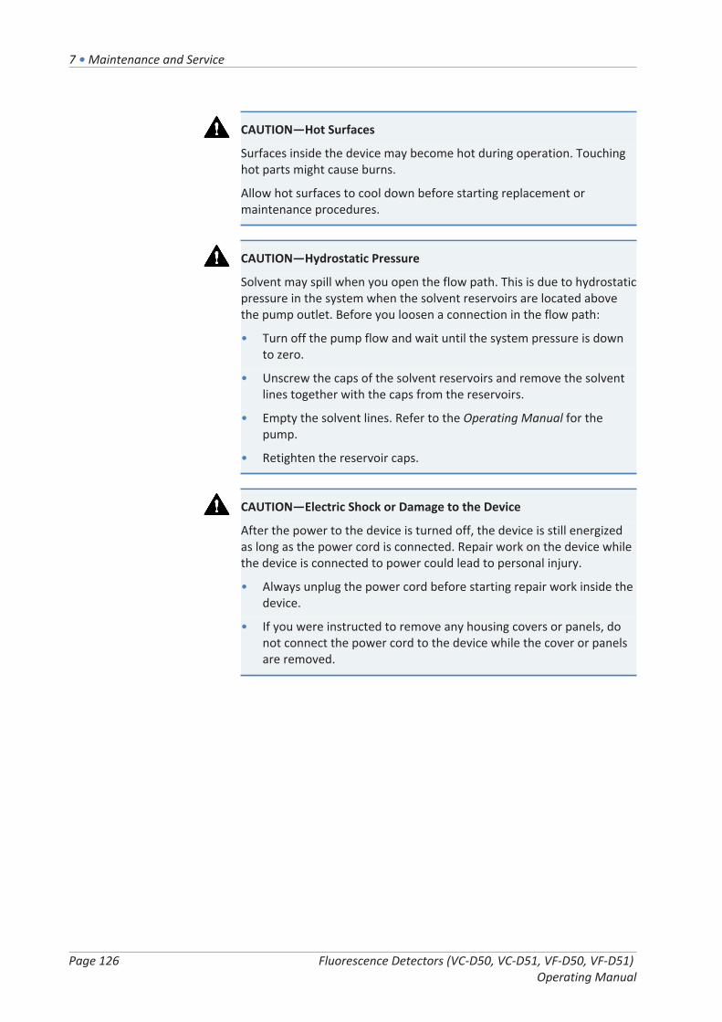
7 • Maintenance and Service
Page 126 Fluorescence Detectors (VC-D50, VC-D51, VF-D50, VF-D51) Operating Manual
CAUTION—Hot Surfaces
Surfaces inside the device may become hot during operation. Touchinghot parts might cause burns.
Allow hot surfaces to cool down before starting replacement ormaintenance procedures.
CAUTION—Hydrostatic Pressure
Solvent may spill when you open the flow path. This is due to hydrostaticpressure in the system when the solvent reservoirs are located abovethe pump outlet. Before you loosen a connection in the flow path:
• Turn off the pump flow and wait until the system pressure is downto zero.
• Unscrew the caps of the solvent reservoirs and remove the solventlines together with the caps from the reservoirs.
• Empty the solvent lines. Refer to the Operating Manual for thepump.
• Retighten the reservoir caps.
CAUTION—Electric Shock or Damage to the Device
After the power to the device is turned off, the device is still energizedas long as the power cord is connected. Repair work on the device whilethe device is connected to power could lead to personal injury.
• Always unplug the power cord before starting repair work inside thedevice.
• If you were instructed to remove any housing covers or panels, donot connect the power cord to the device while the cover or panelsare removed.

7 • Maintenance and Service
Fluorescence Detectors (VC-D50, VC-D51, VF-D50, VF-D51) Operating Manual
Page 127
7.3 General Rules for Maintenance and ServiceFor successful maintenance and service procedures, follow these rulesand recommendations:
• Before starting maintenance or service procedures, shut down thedevice when instructed to do so.
• Use only the replacement parts specifically authorized and qualifiedfor the device by Thermo Fisher Scientific.
• Follow all instructions step by step and use the tools recommendedfor the procedure.
• Before opening the flow path to replace capillaries in the system,turn off the pump flow and wait until the system pressure is down tozero.
• Dirty components can contaminate the chromatography system.Contamination leads to poor performance of the modules and entiresystem or can even cause damage to the modules and system.Therefore:
¨ Always wear appropriate gloves.
¨ Place the components only on a clean, lint-free surface.
¨ Keep your tools clean.
¨ Use only lint-free cloth for cleaning.
• If you need to return the device for depot repair, follow theinstructions in Transporting or Shipping the Device ( page 146).
See also
2 Consumables and Replacement Parts ( page 175)

7 • Maintenance and Service
Page 128 Fluorescence Detectors (VC-D50, VC-D51, VF-D50, VF-D51) Operating Manual
7.4 Routine and Preventive MaintenanceOptimum device performance, maximum uptime of the device, andaccurate results can be obtained only if the device is in good conditionand properly maintained.
7.4.1 Maintenance Plan
Perform the maintenance procedures in the table on a regular basis. Thefrequency given in the table is a suggestion. The optimum frequency formaintenance depends on several factors, such as the types and amountsof samples and solvents used with the device.
Frequency What you should do...
Daily • Inspect the flow connections for signs of leakage orblockage.
• When you use buffers or salt solutions, flush the devicethoroughly after use with an appropriate solvent thatdoes not contain buffers or salts. Monitor thebackpressure that the flow cell is exposed to.
Regularly • Inspect the flow connections for damage, such as cracks,nicks, cuts, or blockage.
• Perform operational qualification and check the lamp ageas required by the application.
• Check that all warning labels are still present on thedevice and clearly legible. If they are not, contact ThermoFisher Scientific for replacement.
Annually Have Thermo Fisher Scientific service personnel performpreventive maintenance once a year.
TIP The Chromeleon software supports functions for monitoring andrecording service and qualification information (see Monitoring theLamp Age ( page 131)).
7.4.2 Cleaning or Decontaminating the Device
Cleaning and decontamination must be performed by qualifiedpersonnel wearing suitable personal protective equipment. Alwaysobserve national and local regulations.
NOTICE
Wipe up all liquids spilled onto the system immediately. If surfaces areexposed for longer periods, these liquids can cause damage.

7 • Maintenance and Service
Fluorescence Detectors (VC-D50, VC-D51, VF-D50, VF-D51) Operating Manual
Page 129
Decontamination
Decontamination is required, for example, when leakage or spillage hasoccurred, or before service or transport of the device. Use a suitablecleaning detergent or disinfectant to ensure that the treatment rendersthe device safe to handle.
Parts required
• Suitable cleaning detergent (or disinfectant)
• Purified water
• Lint-free cloths or wipes
CAUTION—Explosive Gas Mixtures from Alcoholic Cleaning Detergents
Alcohol-containing cleaning detergents may form flammable andexplosive gas mixtures when exposed to air.
• Use such cleaning detergents only when required and only inadequately ventilated rooms.
• Avoid open flames or exposure to excessive heat during the cleaningprocess.
• Wipe the cleaned components thoroughly dry after cleaning. Do notoperate the device before it is completely dry.
NOTICE
Observe the following:
• Only use cleaning detergents that will not damage the surfaces ofthe system.
• Never use sharp tools or brushes for cleaning any surfaces.
• Do not use sprays for cleaning.
• Prevent cleaning detergent from entering the flow path.
• Do not use excessively wetted cloth or wipes for cleaning. Preventany liquids from entering the functional components of the device.Liquids can cause a short circuit when getting in contact with theelectronic components.
NOTICE—Flow Cell Opening
The optical ports and the contact pad for the identification chip in theflow cell opening are sensitive to electrostatic discharge, contaminationand scratches.
Do not touch any surfaces or optical ports in the flow cell opening.

7 • Maintenance and Service
Page 130 Fluorescence Detectors (VC-D50, VC-D51, VF-D50, VF-D51) Operating Manual
Preparations
1. Turn off the power to the device and disconnect the power cordfrom the power source.
Follow these steps
1. Wipe the surfaces clean with a clean, dry, soft, lint-free cloth orwipe. If necessary, slightly dampen the cloth or wipe with a solutionof lukewarm water and a suitable cleaning detergent.
2. Allow the cleaning detergent to react as recommended by themanufacturer.
3. Wipe the cleaned surfaces with purified water to ensure that allcleaning detergent residues have been removed.
4. Wipe the surfaces dry using a soft, lint-free cloth or wipe.
7.4.3 Predictive Performance
The Chromeleon software supports functions for monitoring andrecording service and qualification information about the device.
Monitoring service and qualification intervals
On special service and qualification panels, you can define intervals forservice procedures or qualification procedures. These functions, whichare called Predictive Performance, allow you to schedule theseprocedures based on the actual operating and usage conditions of thedevice. In addition, you can set limits to alert you before and when theservice or qualification is due.
Color-coded bars provide visual feedback, allowing you to easily checkand monitor the status. If a warning limit was set, a message in theChromeleon Audit Trail alerts you when the action is due.
Service and qualification counters can be reset to zero after the requiredaction was performed. To keep the Predictive Performance informationup-to-date, consider resetting the counter when a service, orqualification procedure has been performed.
For more information, refer to the Chromeleon Help.

7 • Maintenance and Service
Fluorescence Detectors (VC-D50, VC-D51, VF-D50, VF-D51) Operating Manual
Page 131
7.4.4 Monitoring the Lamp Age
The Chromeleon software supports functions for monitoring the lampage. This function can help to decide when a lamp is due to be replaced.
The flash lamp can produce about 1-1.5x10⁹ flashes before it needsreplacement only if the performance of the detector is no longersufficient. Thus, the lifetime for the flash lamp depends on the flashfrequency, and therefore the selected lamp mode. Based on the numberof lamp flashes, the Chromeleon software calculates a value thatindicates how many hours the lamp was operated. The value is based onthe assumption that the lamp was operated in Standard mode. For thecalculation of the expected lamp lifetime, one operating hour isweighted depending on the selected lamp mode.
Mode 1 operating hour is counted as ... Expected lamp lifetime
LongLife 0.25 hours approx. 16000 hours
Standard 1 hour approx. 4000 hours
HighPower 3 hours approx. 1300 hours
Example: If the lamp age in Chromeleon indicates 2000 hours, thismeans that the lamp has reached about the half of its lifetime. Thus, ifthe lamp is operated in LongLife mode, it is expected to operate foranother 8000 hours.
In Chromeleon, check the EffectiveLampAge parameter. If the valueexceeds 4000 hours, the lamp should be replaced. Note that the lampmust be replaced only by a Thermo Fisher Scientific service engineer.The service engineer will reset the lamp age counter to zero after thelamp was replaced.
TIP You can extend the lifetime of the xenon flash lamp by switchingbetween lamp modes during a chromatographic run.
See also
2 Lamp Mode ( page 115)

7 • Maintenance and Service
Page 132 Fluorescence Detectors (VC-D50, VC-D51, VF-D50, VF-D51) Operating Manual
7.5 Performing a Wavelength CalibrationA simple initialization procedure is performed after power-up of thedetector. This requires that a flow cell is installed in the detector. Fordetails, see Power On/Off Control ( page 95).
To ensure optimum performance and wavelength accuracy, perform awavelength calibration using water (Raman measurement). Duringwavelength calibration, the light spectrum of the xenon flash lamp isused to calibrate the excitation wavelength. Afterward, the emissionmonochromator is adjusted with the help of the maximum of the Ramanemission spectrum (397 nm).
When
• After the flow cell has been installed or replaced
• After the lamp has been replaced (performed by service engineer)
• If wavelength validation fails
Preparations
The following conditions must be met for both wavelength validationand Raman wavelength calibration:
• The system is equilibrated and environmental conditions are stable.
• There are no air bubbles in the flow cell. We recommend degassingthe water. Set a flow rate of 0.5 mL/min and wait about 15 minutesbefore you begin, until the baseline is stable.
• The water has no impurities. Always use fluorescence-grade waterand consider using a filter or a suitable column before the detector.
To perform a wavelength calibration
You can perform wavelength calibration via Chromeleon. Wavelengthcalibration can take a few minutes. During this time, data acquisition isnot possible.
1. Execute the CalibrateRaman command to start the calibration.The following message appears in Chromeleon:
Make sure that
¨ the system is equilibrated and conditions are stable
¨ fluorescence-grade water is flowing through the cell
¨ the water is degassed (no air bubbles) and free of particles

7 • Maintenance and Service
Fluorescence Detectors (VC-D50, VC-D51, VF-D50, VF-D51) Operating Manual
Page 133
2. Confirm with OK if you are sure that the above conditions are met.The calibration run may take up to five minutes. The new calibrationvalues are stored in the detector.
3. Perform wavelength validation.
See also
2 Performing a Wavelength Validation ( page 134)

7 • Maintenance and Service
Page 134 Fluorescence Detectors (VC-D50, VC-D51, VF-D50, VF-D51) Operating Manual
7.6 Performing a Wavelength ValidationYou can validate the wavelength calibration using water (Ramanmeasurement). If validation fails, that is, if the measured valuessignificantly deviate from the calibration values, you can perform awavelength calibration using water (Raman measurement). The lightspectrum of the xenon flash lamp is used to validate the excitationwavelength.
When
• After (re)installation of the detector
• After wavelength calibration
Preparations
The following conditions must be met for both wavelength validationand Raman wavelength calibration:
• The system is equilibrated and environmental conditions are stable.
• There are no air bubbles in the flow cell. We recommend degassingthe water. Set a flow rate of 0.5 mL/min and wait about 15 minutesbefore you begin, until the baseline is stable.
• The water has no impurities. Always use fluorescence-grade waterand consider using a filter or a suitable column before the detector.
To perform a wavelength validation
You can perform wavelength validation via Chromeleon. Wavelengthvalidation can take a few minutes. During this time, data acquisition isnot possible.
1. Execute the ValidateRaman command to start the validation.The following message appears in Chromeleon:
Make sure that
¨ the system is equilibrated and conditions are stable
¨ fluorescence-grade water is flowing through the cell
¨ the water is degassed (no air bubbles) and free of particles

7 • Maintenance and Service
Fluorescence Detectors (VC-D50, VC-D51, VF-D50, VF-D51) Operating Manual
Page 135
2. Confirm with OK if you are sure that the above conditions are met.The validation run may take up to five minutes. The result("passed"/"failed") is displayed in the Chromeleon Audit Trail.
¨ Passed: The wavelength accuracy is within specification. Theexact wavelength can be found under RamanValidationWL. Theideal value for the measurement is 397 nm.
¨ Failed: The calibration of the detector is not sufficient. Performa wavelength calibration. If wavelength validation fails againafter the recalibration, check the causes and remedial actionsoutlined below.
Possible Cause Remedial Action
Flow cell incorrectlyinstalled
Verify that the flow cell is seated correctly and thatthe screws are tightened finger-tight.
The system does not meetthe required conditions.
Observe the conditions for wavelength validation andcalibration. If the procedure is repeatedly interrupted,contact Service.
Flow cell contaminated Clean the flow cell.
See also
2 Performing a Wavelength Calibration ( page 132)
2 Cleaning the Flow Cell ( page 138)
7 • Maintenance and Service
Page 136 Fluorescence Detectors (VC-D50, VC-D51, VF-D50, VF-D51) Operating Manual
7.7 Flow CellThis section describes cleaning and replacement of flow cells. No toolsare required to remove and install a flow cell.
7.7.1 Guidelines for Handling Flow Cells
NOTICE
Flow cells are highly sensitive to dirt and dust. Observe the followingnotes when handling flow cells:
• When holding flow cells, do not touch the optical block of the flowcell or the sensitive electronics on the flow cell rear side.
• The optical ports of the flow cell are sensitive to contamination andscratches. Do not touch the optical ports of the flow cell or immersethem.
• To avoid damage to the optical ports of the flow cell, be carefulwhen inserting the flow cell into the flow cell opening of the device.
• On the rear side of the flow cell, the contact pads for theidentification chip are located. Never touch the contact pads. Avoiddamage to the electronics of the ID chip.
• Particulate matter, dust and debris can lead to contamination andclogging of the flow cell. If capillaries are removed from the flow cellinlet and outlet, install protective plugs to close the ports and toprevent particles from clogging the flow cell in the next application.Always use the plugs that were installed when the flow cell wasshipped.
• Use the dedicated packaging when storing or transporting the flowcell.
7.7.2 Removing the Flow Cell
Parts required
• Flow cell packaging
• Cover for the flow cell opening on the device
Preparations
1. Flush the flow cell, for example, with isopropanol to rinse out anysolvents.
2. Stop the pump flow.

7 • Maintenance and Service
Fluorescence Detectors (VC-D50, VC-D51, VF-D50, VF-D51) Operating Manual
Page 137
Follow these steps
CAUTION—Hot surface
The flow cell may become hot. Touching a hot flow cell might causeburns.
• Touch the flow cell briefly and carefully to find out if it is hot beforeyou remove the flow cell.
• If the flow cell is hot, allow the flow cell to cool down before youremove it. Make sure the flow cell temperature control is turned off.
1. Disconnect the capillaries from the flow cell inlet and outlet.
2. Close the flow cell inlet and outlet with the flow cell plugs that wereinstalled when the flow cell was shipped.
3. Loosen the two flow cell screws until they are loose. The screws arecaptive in the flow cell and do not need to be removed.
4. Remove the flow cell from the flow cell opening.
5. Install the flow cell cover to the flow cell opening. Tighten the twoscrews finger-tight (no tools required).
Figure 36: Installing the flow cell cover
No. Description
1 Flow cell cover screws
2 Flow cell cover
NOTICEThe flow cell opening on the device is sensitive to dust and debris.
If no flow cell is installed to the device, close the flow cell opening withthe cover for the flow cell opening.
6. To store or ship the flow cell, place it in its packaging.

7 • Maintenance and Service
Page 138 Fluorescence Detectors (VC-D50, VC-D51, VF-D50, VF-D51) Operating Manual
7.7.3 Cleaning the Flow Cell
When
When you suspect that eluent or sample components may havedeposited on the flow cell windows.
Parts required
• Flushing and injection kit for flow cells (optional)
• HPLC-grade water
• 0.1 M nitric acid
WARNING—Health Risk
The handling of solvents can pose health and safety risks.
Wear personal protective equipment as required by the hazard andfollow good laboratory practice. Refer to the material handling andsafety data sheet provided by the vendor.
Follow these steps
You can perform the following procedure by using the optional flushingand injection kit.
1. Flush the flow cell with HPLC-grade water.
2. Fill the flow cell with 0.1 M nitric acid using the optional flushing andinjection kit.
3. Flush the flow cell with HPLC-grade water until the solvent leavingthe flow cell is neutral (pH 7).
4. If cleaning the flow cell does not eliminate the problem, install a newflow cell.

7 • Maintenance and Service
Fluorescence Detectors (VC-D50, VC-D51, VF-D50, VF-D51) Operating Manual
Page 139
7.7.4 Installing the Flow Cell
Parts required
Flow cell
Follow these steps
1. Insert the flow cell straight into the flow cell opening.
Figure 37: Inserting the flow cell
2. Tighten the flow cell screws hand-tight.
3. Install the capillaries to the flow cell. Follow the instructions inSetting Up the Flow Connections ( page 64). Turn on the flow andcheck that all connections are tight.
4. Close the device doors to allow detection of the flow cell. As analternative, press the INIT button on the keypad.
5. Perform wavelength calibration.
See also
2 Performing a Wavelength Calibration ( page 132)

7 • Maintenance and Service
Page 140 Fluorescence Detectors (VC-D50, VC-D51, VF-D50, VF-D51) Operating Manual
7.8 Replacing the Main Power FusesWhen
Blown fuses
Parts required
Fuses (2 fuses, 3.15 AT, 250 V AC, slow-blow, 5 x 20 mm) from Fuses Kit
Tools required
Slotted screwdriver, any size between 3.3 mm and 5.5 mm isappropriate
Preparations
WARNING—Electric Shock
High voltages are present inside the device that could cause an electricshock or damage to the device.
• Turn off the device with its main power switch. Disconnect thepower cord from both the power source and the device.
• Use only the fuses of the type and current rating specified for thedevice by Thermo Fisher Scientific.
• Do not use repaired fuses and do not short-circuit the fuse holders.
Follow these steps
The fuse holder is located next to the main power switch.
Figure 38: Fuse holder
No. Description
1 Main power switch (on/off control)
2 Fuse holder
3 Power-inlet connector

7 • Maintenance and Service
Fluorescence Detectors (VC-D50, VC-D51, VF-D50, VF-D51) Operating Manual
Page 141
1. Use the screwdriver to remove the fuse holder.
2. Replace the two fuses with new fuses of the specified type andcurrent rating. Always replace both fuses.
3. Reinstall the fuse holder.
4. Reconnect the power cord to the power source and to the device.
5. Turn on the device with the main power switch.

7 • Maintenance and Service
Page 142 Fluorescence Detectors (VC-D50, VC-D51, VF-D50, VF-D51) Operating Manual
7.9 Updating the Device FirmwareWhen
Updating the device firmware might be required, for example, when anew firmware version is released that adds functionality or solvesproblems of a previous version.
Items required
Firmware version/Chromeleon version as appropriate
TIP When a new firmware version is released, the new version will beincluded in the next available Chromeleon version. The new firmwarewill not be transferred automatically to the device when you install theChromeleon version.
Preparations
1. Read the release notes provided with the firmware and/orChromeleon version.
2. Connect the device in the Chromeleon software.
3. Stop all operations on the Instrument that includes the device.
4. Wait until the Instrument is idle.
Follow these steps
1. Start the Instrument Configuration Manager program.
2. Perform a firmware update from the General tab page in theconfiguration dialog box for the device. For details, refer to theChromeleon Help.The firmware update may take several minutes.
NOTICE
A firmware downgrade or incomplete firmware update may result in lossof functionality or malfunctioning of the device.
• Do not interrupt communication between the Chromeleon softwareand the device at any time during the procedure.
• At the beginning of the update process, a message appears showingthe firmware version currently installed in the device and theversion that will be transferred from the Chromeleon software. Ifthe firmware installed in the device is a later version than theversion in the Chromeleon software, cancel the download.

7 • Maintenance and Service
Fluorescence Detectors (VC-D50, VC-D51, VF-D50, VF-D51) Operating Manual
Page 143
3. Monitor the Audit Trail of the Instrument Configuration Managerprogram to see whether the firmware update was successful orfailed.
¨ If the firmware update failed, turn the device off and on againand repeat the firmware update.
¨ If the firmware update fails repeatedly, contact Thermo FisherScientific Technical Support for assistance.
4. After a successful firmware update, requalification of the device maybe required. See the release notes for a recommendation.

7 • Maintenance and Service
Page 144 Fluorescence Detectors (VC-D50, VC-D51, VF-D50, VF-D51) Operating Manual
7.10 Replacing the DoorsWhen
Damage of door
TIP The maintenance procedures do not require that you remove thedoors. If this should ever be required for a specific reason or procedure,follow the related steps in this section.
Parts required
Replacement door
Follow these steps
NOTICE
To avoid damage to the door hinges, be careful when performing thefollowing sequence of steps and do not apply force.
1. To remove a door, push the door upward while opening.Open the door to a position in which the two hinges on the housingare aligned in the grooves on the door. You can remove the dooronly when the hinges are in the grooves.
Figure 39: Unhinging a door
No. Description
1 Hinge on the housing
2 Reception groove on the door
2. Slightly tilt the door to the outside, away from the housing, andremove the door.

7 • Maintenance and Service
Fluorescence Detectors (VC-D50, VC-D51, VF-D50, VF-D51) Operating Manual
Page 145
3. To install the door, align the door with the hinges on the housing. Becareful not to clamp tubing or capillaries between the door and theenclosure.
4. Insert the hinges in the groove, by pushing up and slightly turningthe door.
5. Push the door downward to lock it in place.You can close the door only when it is properly installed.

7 • Maintenance and Service
Page 146 Fluorescence Detectors (VC-D50, VC-D51, VF-D50, VF-D51) Operating Manual
7.11 Transporting or Shipping the DeviceIf you want to transport the device to a new location or if you need toship the device, first prepare the device for transport and then move orship the device as required. Follow the instructions in this section.
Observe the following safety guidelines:
CAUTION—Heavy Load, Bulky Device
The device is too heavy or bulky for one person alone to handle safely.To avoid personal injury or damage to the device, observe the followingguidelines:
• Physical handling of the device, including lifting or moving, requiresa team effort of two persons.
• A team effort is in particular required when lifting the device intothe system stack or when removing it.
• Use the carrying handles that were shipped with the device to moveor transport the device. Never move or lift the device by the frontdoors. This will damage the doors or the device.
Follow these steps
1. Prepare the device for transport. See Preparing the Device forTransport ( page 146).
2. The step depends as follows:
¨ To transport the device to a new location, follow the instructionsin Transporting the Device to a New Location ( page 147).
¨ To ship the device, follow the instructions in Shipping the Device( page 148).
7.11.1 Preparing the Device for Transport
To prepare the device for transport, follow these steps:
1. Perform a long-term shut down of the device (see Long-TermShutdown ( page 119)).
2. Turn off the device with its main power switch and disconnect thepower cord.
3. Remove all cables and flow connections to other devices.
7 • Maintenance and Service
Fluorescence Detectors (VC-D50, VC-D51, VF-D50, VF-D51) Operating Manual
Page 147
4. Remove the flow cell from the device and store it in its packaging.Ensure that you install the flow cell cover to the flow cell opening.Flow cells must be shipped in their original packaging.
NOTICE
The flow cell opening on the device is sensitive to dust and debris.
If no flow cell is installed to the device, close the flow cell opening withthe cover for the flow cell opening.
5. Remove the device or slide-in module from the system stack asrequired:Install the carrying handles and remove the device from theVanquish system. Follow the instructions on dismounting the systemstack in the Transporting or Shipping the System section of theVanquish System Operating Manual.
‑or‑
Remove the slide-in module from the device enclosure in the systemstack (see Removing the Slide-In Module ( page 149)).
See also
2 Removing the Flow Cell ( page 136)
7.11.2 Transporting the Device to a New Location
Preparations
Prepare the device for transport. See Preparing the Device for Transport( page 146).
Follow these steps
1. Observe the notes for handling and lifting the device safely.
2. Transport the device to the new location.
3. Install and set up the device in the system stack. Follow theinstructions on mounting the system stack in the Vanquish SystemOperating Manual.
4. Set up the device:
a) Connect the device and set up flow connections (see Installation( page 47)).
b) Prepare the device for operation (see Preparing the Device forOperation ( page 96)).
5. Before starting an analysis, let the device equilibrate and be surethat it is ready for operation.
7 • Maintenance and Service
Page 148 Fluorescence Detectors (VC-D50, VC-D51, VF-D50, VF-D51) Operating Manual
7.11.3 Shipping the Device
Preparations
Prepare the device for transport. See Preparing the Device for Transport( page 146).
Follow these steps
1. Follow the unpacking instructions in this manual in the reverseorder.Use only the original packing material and shipping container. If theoriginal shipping container is not available, appropriate containersand packing material can be ordered from the Thermo FisherScientific sales organization.
2. If you need to return the device to Thermo Fisher Scientific for depotrepair, contact your local Thermo Fisher Scientific supportorganization for the appropriate procedure.
CAUTION—Possible Contamination
Hazardous substances may have contaminated the device duringoperation and may cause personal injury to service personnel.
• Decontaminate all parts of the device that you want to return forrepair.
• Fill in and sign the Health and Safety Form. Thermo Fisher Scientificrefuses to accept devices for repair if the Health and Safety Form ismissing, incompletely filled in, or unsigned.
Restarting the Device after Shipping
To restart the device after shipping, follow these steps:
1. Follow the unpacking instruction in this operating manual.
2. Install and set up the device in the system stack. Follow theinstructions on mounting the system stack in the Vanquish SystemOperating Manual.
3. Set up the device:
a) Connect the device and set up flow connections (see Installation( page 47)).
b) Prepare the device for first-time operation (see Preparing theDevice for Operation ( page 96)).
4. Before starting an analysis, let the device equilibrate and be surethat it is ready for operation.

7 • Maintenance and Service
Fluorescence Detectors (VC-D50, VC-D51, VF-D50, VF-D51) Operating Manual
Page 149
7.12 Replacing the Slide-In Module
7.12.1 Removing the Slide-In Module
CAUTION—Heavy Load, Bulky Device
The device is too heavy or bulky for one person alone to handle safely.To avoid personal injury or damage to the device, observe the followingguidelines:
• Physical handling of the device, including lifting or moving, requiresa team effort of two persons.
• A team effort is in particular required when lifting the device intothe system stack or when removing it.
Tools required
Screwdriver, Torx T20
Preparations
1. Prepare the device for transport. See Transporting or Shipping theDevice ( page 146).
Follow these steps
1. Loosen the four captive screws on the front left and front right ofthe device.
Figure 40: Captive screws on the slide-in module
2. Push all tubing and capillaries, which are present in the tubing chaseof the Vanquish system modules, into the tubing chase. Otherwise,you will not be able to remove the slide-in module properly from theenclosure in the next step.
3. Grasp the slide-in module by the panel below the flow cell openingor the leak tray, and pull the module out of the enclosure byapproximately 10 cm.

7 • Maintenance and Service
Page 150 Fluorescence Detectors (VC-D50, VC-D51, VF-D50, VF-D51) Operating Manual
Figure 41: Pulling out the slide-in module
NOTICE
The slide-in module can fall down when pulling it out of the enclosuretoo far.
Pull out the slide-in module just far enough so that you can grasp it onboth sides from below.
4. Remove the slide-in module from the enclosure. The following stepsrequire a team effort:
a) Take the slide-in module on both sides from below.
b) Pull the slide-in module from the rails towards the front.
c) Place the slide-in module on a clean and stable surface.
7.12.2 Returning the Slide-In Module
Preparation
If not yet done: Remove the slide-in module from the enclosure. SeeRemoving the Slide-In Module ( page 149).
Follow these steps
1. Install the slide-in module to the enclosure of the replacementdevice. Follow the steps for inserting the slide-in module in theenclosure and tightening the captive screws in Installing the Slide-InModule ( page 151).
2. Follow the instructions in Shipping the Device ( page 148).
7 • Maintenance and Service
Fluorescence Detectors (VC-D50, VC-D51, VF-D50, VF-D51) Operating Manual
Page 151
NOTICE
Shipping the slide-in module improperly leads to damage to the device.
Always ship the slide-in module as described in this operating manual.
CAUTION—Possible Contamination
Hazardous substances may have contaminated the device duringoperation and may cause personal injury to service personnel.
• Decontaminate all parts of the device that you want to return forrepair.
• Fill in and sign the Health and Safety Form. Thermo Fisher Scientificrefuses to accept devices for repair if the Health and Safety Form ismissing, incompletely filled in, or unsigned.
7.12.3 Installing the Slide-In Module
CAUTION—Heavy Load, Bulky Device
The device is too heavy or bulky for one person alone to handle safely.To avoid personal injury or damage to the device, observe the followingguidelines:
• Physical handling of the device, including lifting or moving, requiresa team effort of two persons.
• A team effort is in particular required when lifting the device intothe system stack or when removing it.
Tools required
Screwdriver, Torx T20
Preparations
1. Unpack the replacement device. Remove the slide-in module fromits enclosure as described in Removing the Slide-In Module( page 149).
2. Verify that the device enclosure into which the slide-in module shallbe installed is clean. If required, clean the inner and outer surfacesof the enclosure. See Cleaning or Decontaminating the Device( page 128).
3. When installing the slide-in module to an enclosure in the systemstack, check that the enclosure is placed correctly in the stack.

7 • Maintenance and Service
Page 152 Fluorescence Detectors (VC-D50, VC-D51, VF-D50, VF-D51) Operating Manual
Follow these steps
1. Push all tubing and capillaries, which are present in the tubing chaseof the Vanquish system modules, into the tubing chase. Otherwise,you will not be able to insert the slide-in module properly into theenclosure in the next step.
2. On the slide-in module, check that you can move the captive screwsback and forth with your fingers. If you cannot, screw them in untilyou can.
3. Insert the slide-in module in the enclosure. The following stepsrequire a team effort:
a) Take the slide-in module on both sides from below.
b) Lift the slide-in module to the height of the enclosure.
c) Place the slide-in module in the enclosure so that the modulesits in the enclosure by approximately 25 cm.
d) Push the slide-in module onto the rails and into the enclosureuntil the slide-in module sits completely in the enclosure.
Figure 42: Inserting the slide-in module
4. To facilitate tightening the slide-in module in the enclosure, pull outthe module a few millimeters (approximately 2 to 5 mm).
5. With the screwdriver, move each captive screw back and forth whilepressing inward until the screw slips into the thread.
6. Push the slide-in module back into the enclosure as far as it goes in.
7. Gradually and evenly, tighten the four captive screws on the slide-inmodule hand-tight.

7 • Maintenance and Service
Fluorescence Detectors (VC-D50, VC-D51, VF-D50, VF-D51) Operating Manual
Page 153
NOTICE
• Verify that the screws are tightened. Pull the slide-in module by theleak tray towards the front and check whether the screws move. Ifthey do not move, the slide-in module is installed properly.
• If the screws move, tighten the screws further. With a torquewrench, the recommended torque is 1.2 Nm.
8. Set up and restart the device.
7.12.4 Setting Up the Slide-In Module
After you have reinstalled the slide-in module in the enclosure, set upand restart the device.
Follow these steps
1. Set up the slide-in module:
a) Connect the slide-in module and set up flow connections (seeInstallation ( page 47)).
b) Prepare the slide-in module for first-time operation (seePreparing the Device for Operation ( page 96)).
2. Prepare all other modules of the Vanquish system for operation andrestart them. Refer to the Operating Manuals for the modules.
3. Before starting an analysis, let the chromatography systemequilibrate and be sure that it is ready for operation.
4. In the Chromeleon software, run the device-specific PerformanceQualification (PQ) tests.
5. When the test is completed, update the QualificationDoneparameter.

7 • Maintenance and Service
Page 154 Fluorescence Detectors (VC-D50, VC-D51, VF-D50, VF-D51) Operating Manual
8 • Troubleshooting
Fluorescence Detectors (VC-D50, VC-D51, VF-D50, VF-D51) Operating Manual
Page 155
8 TroubleshootingThis chapter is a guide to troubleshooting issues that may arise duringoperation of the device.

8 • Troubleshooting
Page 156 Fluorescence Detectors (VC-D50, VC-D51, VF-D50, VF-D51) Operating Manual
8.1 General Information about TroubleshootingThe following features help you to identify and eliminate the source forproblems that may arise during operation of the device.
TIP For information about operating issues that might occur during theoperation of a Vanquish system, refer to the Vanquish System OperatingManual.
If you are unable to resolve a problem following the instructions givenhere or if you experience problems that are not covered in this section,contact Thermo Fisher Scientific Technical Support for assistance. Seethe contact information at the beginning of this manual.
To facilitate device identification, have the serial number and technicalname available when communicating with Thermo Fisher Scientific.
Status Indicators
The status indicator LED bar on the front side of the device and theSTATUS LED on the keypad inside provide quick visual feedback on theoperational status of the device. If the device firmware detects aproblem, the status indicators are red. The problem is reported to theChromeleon software and a message appears in the Audit Trail.
Alarms
Leaks are a potential safety issue. Therefore, if a leak sensor detectsleakage, beeping starts to alert you in addition to the message in theChromeleon Audit Trail and the status indicators changing to red. Followthe instructions in this manual to find and eliminate the source for theleakage.
Chromeleon Audit Trail Messages
If the device firmware detects a problem, the problem is reported to theChromeleon software.
The Chromeleon software logs information about all events related toinstrument operation for the current day in an Audit Trail. The AuditTrail is named with the current date, using the format yyyymmdd. Forexample, the Audit Trail for May 15, 2019, is named 20190515.
The Instrument Audit Trails can be found on the ePanel Set (AuditePanel). In addition, Audit Trails for each instrument are available in theConsole Data view, in the folder of the Instrument.

8 • Troubleshooting
Fluorescence Detectors (VC-D50, VC-D51, VF-D50, VF-D51) Operating Manual
Page 157
Messages in the Chromeleon Audit Trail are preceded by an icon. Theicon identifies the seriousness of the problem (refer to the ChromeleonHelp). For possible causes and remedial actions, see Messages( page 158).

8 • Troubleshooting
Page 158 Fluorescence Detectors (VC-D50, VC-D51, VF-D50, VF-D51) Operating Manual
8.2 MessagesThe table lists the most frequently observed messages for the deviceand provides troubleshooting assistance.
Each message consists of a code number and a text. The code number isthe unique identifier for the problem while the wording may change.Note the following:
• To facilitate finding a message, the table lists the messages sorted bycode.
• If you cannot find the code you are looking for, check the messagetext. The two messages "Unexpected module behavior" and"Module malfunction detected" can be assigned to different codes.See the beginning of the table for more information.
TIP If you are unable to resolve the problem following the instructions inthis manual, or if you encounter a message not listed in the table, writedown the code and wording of the message and contact us. For details,see the Contacting Us section at the beginning of this manual.
Message and Code Description and Remedial Action
Unexpected module behavior. Codexx
xx = Two-digit to four-digit code number.When the message appears, write down the message code and turnoff the module. Wait for 5 seconds and turn on the module again.TIP If the message appears with code 103, additional remedial actionsare available. See further down this table.If the message appears again, contact Technical Support.
Module malfunction detected. Codexx
xx = Two-digit to four-digit code number.When the message appears, write down the message code. Turn offthe module and contact Technical Support.
Code 33 Leak detected – eliminatewithin approx. xx seconds.
xx = the number of seconds within the leak must be resolvedFind and eliminate the source for the leakage (see Resolving LiquidLeaks ( page 162)).
Code 34 Leak detected. Find and eliminate the source for the leakage (see Resolving LiquidLeaks ( page 162)).
Code 36 Download failed. The firmware download has not been successful. Verify that thecorrect firmware file was selected. Repeat the download.
Code 37 Download firmwaremismatch.
The firmware download has not been successful. Verify that thecorrect firmware file was selected. Repeat the download.

8 • Troubleshooting
Fluorescence Detectors (VC-D50, VC-D51, VF-D50, VF-D51) Operating Manual
Page 159
Message and Code Description and Remedial Action
Code 89 Liquid leak sensor missing ordefective.
Verify that the leak sensor is installed and the cable connector isproperly connected. Contact Thermo Fisher Scientific TechnicalSupport for assistance if the leak sensor is defective.To operate the device nevertheless, you can disable the leak sensorfunctionality in the Chromeleon software by setting LeakSensorModeto Disabled.
Code 90 Download firmwaremismatch – invalid version.
You tried to download a firmware with an earlier version numberthan the firmware that is currently installed in the device.Downgrading the firmware may result in loss of functionality ormalfunctioning of the device. If required, repeat the download with afirmware version later than the version currently installed in thedevice.
Code 103 Unexpected modulebehavior – limited features available.
The firmware may be defective or a firmware downgrade has beenperformed.Update the firmware to the current revision. See Updating the DeviceFirmware ( page 142).
Code 118 USB Buffer Overflow. This is a software problem. The module produces data faster than thecomputer on which the Chromeleon software is running reads thedata.1. In the Chromeleon software, disconnect and reconnect themodule.2. If this does not solve the problem, update the firmware or theChromeleon software version.3. If the problem persists: Also, third-party software on the computer,for example, virus scanners, can cause the problem. Contact theonsite IT department.
Code 120 The request timed out. Communication with the module failed. The module did not respondin time.For the module for which the message appears:1. Turn on the module if it is not yet turned on.2. Check the system interlink cables for proper connection.
Code 8013 No flow cell detected Verify that the flow cell is properly installed. The lamp isautomatically turned off when a flow cell is missing.
Code 8032 Unexpected modulebehavior. Flow cellCode 8033 Unexpected modulebehavior. Flow cell
If the message indicates "Flow cell": Verify that the flow cell isproperly installed. Open and close the doors. Turn off the detector.Wait for 5 seconds and turn on the detector again. Replace the flowcell and try again. If the message appears again, contact TechnicalSupport.
Code 8035 Signal overflow in<channel name>
The reference signal is too low, or the PMT signal is too high. Check ifthe flow cell is contaminated. Consider cleaning or replacing the flowcell. Check if the sample concentration is too high, and make surethat the excitation wavelength is set to a wavelength above the UVcutoff wavelength of the eluent. The lamp may be too old and mayhave to be replaced.
Code 8036 Reference signal too lowin <channel name>
The reference signal is too low (high absorption). Check if the flowcell is contaminated. Consider cleaning or replacing the flow cell.Check if the sample concentration is too high, and make sure that theexcitation wavelength is set to a wavelength above the UV cutoffwavelength of the eluent. The lamp may be too old and may have tobe replaced.

8 • Troubleshooting
Page 160 Fluorescence Detectors (VC-D50, VC-D51, VF-D50, VF-D51) Operating Manual
Message and Code Description and Remedial Action
Code 8049 Command rejected - closefront door first
It is not possible to start data acquisition with the front doors open.Close the doors and try again.
Code 8051 Flow cell detected. It isrecommended executing thecommand CalibrateRaman
A new flow cell was found. It is recommended to perform a Ramanwavelength calibration (see Performing a Wavelength Calibration( page 132)); without calibration, wavelengths may deviate from theactual wavelength by up to a few nanometers.
Code 8064 PMT x signal overflow in<channel name>Code 8065 PMT x signal overflowduring scan
With x = PMT 1 or 2Signal overflow in PMT 1 or 2 occurred. Repeat the run or scan with alower sensitivity or lower concentration of the sample.
Code 8071 PMT Sensitivity autorangefor <channel name> -new Sensitivityis x
With x = The new sensitivity value after the adjustment.The detector had to automatically reduce the Sensitivity. Select asuitable Sensitivity (see Sensitivity (Detector Sensitivity) ( page 108))and repeat. x indicates the new sensitivity value after the adjustment.Use this value, or a smaller value, in your method when you expectsimilar concentrations.
Code 8078 PMT Autorange for<channel name> not possible -already minimal Sensitivity
The detector could not automatically reduce the Sensitivity, as theSensitivity setting is already set to a minimum. Repeat with a lowerconcentration of the sample, or smaller injection volume.
Code 8087 System Interlink error The System Interlink connection got lost. Check that all SystemInterlink cables on the Vanquish system are properly connected.
Code 8093 Not initialized The detector is not initialized. Verify that a flow cell is installedcorrectly and that the eluent composition in the flow cell does notchange and no air bubbles are present. Then open and close thedoors, or press INIT on the keypad.
Code 8100 - Code 8109 Calibration ofxx failed.
With x = Name of the component for which calibration failed.Cause details• Raman calibration failed.• The flow cell may be installed incorrectly.• The flow cell may be contaminated.Remedial actions• Observe the conditions for wavelength calibration (see Performing a
Wavelength Calibration ( page 132)) and wavelength validation(see Performing a Wavelength Validation ( page 134)).
• Verify that the flow cell is installed correctly and that the screws aretightened finger-tight.
• Clean the flow cell (see Cleaning the Flow Cell ( page 138)) ifnecessary.
• Make sure that the flow cell is properly equilibrated. Make sure thatyou use degassed solvents.
If the procedure is repeatedly interrupted, contact Technical Support.

8 • Troubleshooting
Fluorescence Detectors (VC-D50, VC-D51, VF-D50, VF-D51) Operating Manual
Page 161
Message and Code Description and Remedial Action
Code 8111 - Code 8115 Calibration ofxx failed.
With x = Name of the component for which calibration failedCause detailsRaman calibration failed.Remedial actions• Observe the conditions for wavelength calibration (see Performing a
Wavelength Calibration ( page 132)) and wavelength validation(see Performing a Wavelength Validation ( page 134)).
• Verify that the flow cell is installed correctly and that the screws aretightened finger-tight.
• Clean the flow cell (see Cleaning the Flow Cell ( page 138)) ifnecessary.
• Make sure that the flow cell is properly equilibrated and no airbubbles are present. Make sure that you use degassed solvents.
If the procedure is repeatedly interrupted, contact Technical Support.
Code 8116 and 8118 to 8121Initialization failed
Cause details• The detector could not initialize.• The flow cell may be contaminated.Remedial actions• Verify that a flow cell is installed correctly.• Verify that the eluent composition in the flow cell does not change
and no air bubbles are present. Make sure that you use degassedsolvents.
• Clean the flow cell (see Cleaning the Flow Cell ( page 138)) ifnecessary.

8 • Troubleshooting
Page 162 Fluorescence Detectors (VC-D50, VC-D51, VF-D50, VF-D51) Operating Manual
8.3 Operating IssuesThis section gives an overview of possible operating issues and remedialactions.
8.3.1 Resolving Liquid Leaks
When
The leak sensor is wet. The leak sensor reports leakage.
Parts and additional items required
• Replacement part as required
• Cloth or tissue
Preparations
When resolving leakage, observe the safety guidelines and general rulesfor maintenance and service as presented in Maintenance and Service( page 123).
Follow these steps
1. Locate the source of the leak. Leakage usually occurs at aconnection. However, leakage may also have occurred inside theflow cell.
Location of the leak Steps
Flow cell inlet and/or outlet 1. Tighten the connection where liquid isvisible.
2. If the connection seems tight but is stillleaking, remove the connection/fittingand check for damage.
3. If necessary, replace the inlet capillaryor waste line.
Leak tray but not flow cell inlet or outlet 1. Remove the flow cell from the detectorand inspect the flow cell for signs ofleakage.
2. If signs of leakage are present at theflow cell, carefully dry the flow cellopening in the detector and letremaining moisture evaporate beforeyou replace the flow cell.
3. With a cloth or tissue, thoroughly absorb all liquid that has collectedin the leak tray and under the leak sensor. Be careful not to bend thesensor.

8 • Troubleshooting
Fluorescence Detectors (VC-D50, VC-D51, VF-D50, VF-D51) Operating Manual
Page 163
4. Allow the sensor to adjust to the ambient temperature for a fewminutes.
5. If leakage is no longer reported, you can resume operation.
See also
2 Removing the Flow Cell ( page 136)
2 Installing the Flow Cell ( page 139)
8.3.2 Additional Device Operating Issues
This section provides additional issues that may arise during operation ofthe Vanquish device. Locate the table for the type of symptom you have,find the possible cause, and use the description of the solution to helpyou solve your problem quickly.
Also check the Chromeleon Audit Trail for a related message if anoperating problem occurs. The message may provide additionalinformation.
Note that this section provides information on symptoms and causesdirectly related to the Vanquish device. For information abouttroubleshooting for the Vanquish system, refer to the Vanquish SystemOperating Manual.
TIP If you are unable to resolve a problem following the instructionsgiven here or if you experience problems that are not covered in thissection, contact Thermo Fisher Scientific Technical Support forassistance.
Symptom Possible Cause Remedial Action
Peak tailing Fluorescence detectorflow cell inlet and outletexchanged
Verify that the flow cell inlet and outlet in afluorescence detector are connected correctly.
Negative peaks Absorption/fluorescenceof analyte lower than ofmobile phase
Select different UV or fluorescence detectionwavelengths.Use a mobile phase with less backgroundabsorption/ fluorescence.Dissolve the sample in mobile phase.
Fluorescence of thesubstance or eluent isquenched by othercomponents
Consider using the negative peaks forquantification.
Markers in fluorescencesignal
The Sensitivity wasautomatically reduced
Select a lower Sensitivity for your application. Thesample audit trail informs to which level theSensitivity was reduced to.
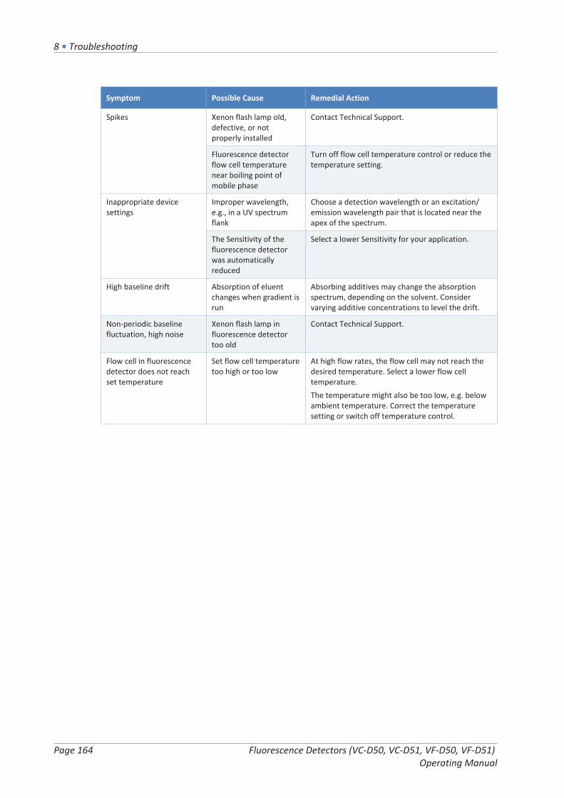
8 • Troubleshooting
Page 164 Fluorescence Detectors (VC-D50, VC-D51, VF-D50, VF-D51) Operating Manual
Symptom Possible Cause Remedial Action
Spikes Xenon flash lamp old,defective, or notproperly installed
Contact Technical Support.
Fluorescence detectorflow cell temperaturenear boiling point ofmobile phase
Turn off flow cell temperature control or reduce thetemperature setting.
Inappropriate devicesettings
Improper wavelength,e.g., in a UV spectrumflank
Choose a detection wavelength or an excitation/emission wavelength pair that is located near theapex of the spectrum.
The Sensitivity of thefluorescence detectorwas automaticallyreduced
Select a lower Sensitivity for your application.
High baseline drift Absorption of eluentchanges when gradient isrun
Absorbing additives may change the absorptionspectrum, depending on the solvent. Considervarying additive concentrations to level the drift.
Non-periodic baselinefluctuation, high noise
Xenon flash lamp influorescence detectortoo old
Contact Technical Support.
Flow cell in fluorescencedetector does not reachset temperature
Set flow cell temperaturetoo high or too low
At high flow rates, the flow cell may not reach thedesired temperature. Select a lower flow celltemperature.The temperature might also be too low, e.g. belowambient temperature. Correct the temperaturesetting or switch off temperature control.
9 • Specifications
Fluorescence Detectors (VC-D50, VC-D51, VF-D50, VF-D51) Operating Manual
Page 165
9 SpecificationsThis chapter provides the physical and performance specifications,including information about the materials used in the flow path of thedevice.

9 • Specifications
Page 166 Fluorescence Detectors (VC-D50, VC-D51, VF-D50, VF-D51) Operating Manual
9.1 Performance Specifications
9.1.1 Detector
The device performance is specified as follows:
Type Specification
Optical design Two monochromators with concave holographic gratings and ellipticmirrors for highest efficiency in light transmission
Light source Xenon flash lamp (15W);Three different flash frequencies (HighPower, Standard, LongLife) can beselected.
Reference system Reference sensor behind flow cell for compensation of lamp intensityfluctuations
Wavelength range VC-D50:Excitation: 200 nm - 630 nmEmission: 265 nm - 650 nmNumber of photomultipliers: 1VC-D51:Excitation: 200 nm - 880 nmEmission: 265 nm - 900 nmNumber of photomultipliers: 2VF-D50:Excitation: 200 nm - 630 nmEmission: 220 nm - 650 nmNumber of photomultipliers: 1VF-D51:Excitation: 200 nm - 880 nmEmission: 220 nm - 900 nmNumber of photomultipliers: 2
Spectral bandwidth Excitation: 20 nmEmission: 20 nm
Spectra scanning modes Single spectrum scan modes: Excitation, Emission, SynchronousUnder Chromeleon 7 software:FL Field Acquisition scan modes: Excitation, Emission, Synchronous
Emission filter VC-D50, VC-D51: fixed filter with 280 nmVF-D50, VF-D51: 5 programmable positions (Open, 280 nm, 370 nm,435 nm, 530 nm)
Excitation/emission wavelengthswitching time
< 250 ms
Number of channels VC-D50, VC-D51: single channelVF-D50, VF-D51: up to 4 signal channels

9 • Specifications
Fluorescence Detectors (VC-D50, VC-D51, VF-D50, VF-D51) Operating Manual
Page 167
Type Specification
Data collection rate Adjustable:up to 100 Hz (VC-D50, VC-D51)up to 200 Hz (VF-D50, VF-D51 under Chromeleon 7 software in single-channel mode)up to 4 Hz (VF-D50, VF-D51 in multi-channel mode)
Sensitivity PMT 1:Raman signal-to-noise ratio:>550 ASTM over the entire lifetime of the lamp; test conditions: standardflow cell, fluorescence grade water, excitation 350 nm, emission 397 nm(>2100 with dark current as reference); test conditions: standard flow cell,fluorescence grade water, excitation 350 nm, emission 450 nmPMT 2 (VF-D51 only):Raman signal-to-noise ratio:>225 ASTM; test conditions: standard flow cell, fluorescence grade water,excitation 350 nm, emission 397 nm(>1050 with dark current as reference); test conditions: standard flow cell,fluorescence grade water, excitation 350 nm, emission 450 nm
Wavelength accuracy ± 2 nm (over detector lifetime; excitation and emission monochromatorsindividually)
Wavelength repeatability ± 0.2 nm
Wavelength calibration Internal calibration, excitation monochromator with emission lines ofxenon flash lamp, emission monochromator with Raman shift of water andemission lines of xenon lamp.
Wavelength validation Internal validation, excitation monochromator with emission lines of xenonflash lamp, emission monochromator with Raman shift of water andemission lines of xenon lamp.As the wavelength reading of the Raman peak depends on both excitationand emission wavelength accuracy, the permitted deviation is ± 3 nm.
USB 1 USB port (USB 2.0, "B" type connector)1 USB hub with 3 ports (USB 2.0, "A" type connectors)
I/O Interface 2 digital I/O ports (mini-DIN), each providing one input and one relayoutput
System Interlink 2 System Interlink ports (RJ45-8 connectors)
Analog output 2 analog outputs via optional plug-in expansion board to output emissionchannelsResolution: 20 bitMaximum data rate: 50 HzOutputs can be configured via software (output voltage range 0 to 1 V or0 to 10 V, sensitivity and offset)
Control Chromeleon 7The device can be operated also with other data systems. For details,contact the Thermo Fisher Scientific sales organization.Keypad with 2 buttons for performing certain functions directly from thedevice
Materials in the flow path See the Specifications for the flow cells.
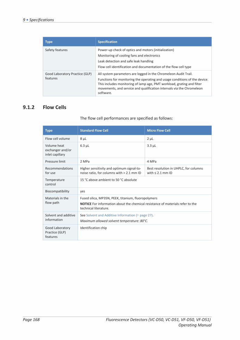
9 • Specifications
Page 168 Fluorescence Detectors (VC-D50, VC-D51, VF-D50, VF-D51) Operating Manual
Type Specification
Safety features Power-up check of optics and motors (initialization)Monitoring of cooling fans and electronicsLeak detection and safe leak handlingFlow cell identification and documentation of the flow cell type
Good Laboratory Practice (GLP)features
All system parameters are logged in the Chromeleon Audit Trail.Functions for monitoring the operating and usage conditions of the device.This includes monitoring of lamp age, PMT workload, grating and filtermovements, and service and qualification intervals via the Chromeleonsoftware.
9.1.2 Flow Cells
The flow cell performances are specified as follows:
Type Standard Flow Cell Micro Flow Cell
Flow cell volume 8 µL 2 µL
Volume heatexchanger and/orinlet capillary
6.3 µL 3.3 µL
Pressure limit 2 MPa 4 MPa
Recommendationsfor use
Higher sensitivity and optimum signal-to-noise ratio, for columns with > 2.1 mm ID
Best resolution in UHPLC, for columnswith ≤ 2.1 mm ID
Temperaturecontrol
15 °C above ambient to 50 °C absolute
Biocompatibility yes
Materials in theflow path
Fused silica, MP35N, PEEK, titanium, fluoropolymersNOTICE For information about the chemical resistance of materials refer to thetechnical literature.
Solvent and additiveinformation
See Solvent and Additive Information ( page 27).Maximum allowed solvent temperature: 80°C.
Good LaboratoryPractice (GLP)features
Identification chip

9 • Specifications
Fluorescence Detectors (VC-D50, VC-D51, VF-D50, VF-D51) Operating Manual
Page 169
9.2 Physical SpecificationsThe physical conditions of the device are specified as follows:
Type Specification
Range of use Indoor use only
Ambient operatingtemperature
5 °C - 35 °C
Ambient storage temperature -20 °C - 45 °C
Ambient operating humidity 20% - 80% relative humidity (non-condensing)
Ambient storage humidity Maximum 60% relative humidity (non-condensing)
Operating altitude Maximum 2000 m above sea level
Pollution degree 2
Power requirements Wide range, 100 – 240 V AC, ± 10 %; 50/60 Hz; max. 245 W / 255 VA
Overvoltage category II
Emission sound pressure level < 50 dB(A)
Dimensions(height x width x depth)
15.9 x 42 x 62 cm
Weight Approx. 21 kg

9 • Specifications
Page 170 Fluorescence Detectors (VC-D50, VC-D51, VF-D50, VF-D51) Operating Manual

10 • Accessories, Consumables and Replacement Parts
Fluorescence Detectors (VC-D50, VC-D51, VF-D50, VF-D51) Operating Manual
Page 171
10 Accessories,Consumables andReplacement PartsThis chapter describes the standard accessories that are shipped withthe device and the accessories that are available as an option. Thischapter also provides information for reordering consumables andreplacement parts.

10 • Accessories, Consumables and Replacement Parts
Page 172 Fluorescence Detectors (VC-D50, VC-D51, VF-D50, VF-D51) Operating Manual
10.1 General InformationThe device must be operated only with the replacement parts andadditional components, options, and peripherals specifically authorizedand qualified by Thermo Fisher Scientific.
Accessories, consumables, and replacement parts are always maintainedat the latest technical standard. Therefore, part numbers are subject tochange. If not otherwise stated, updated parts will be compatible withthe parts they replace.
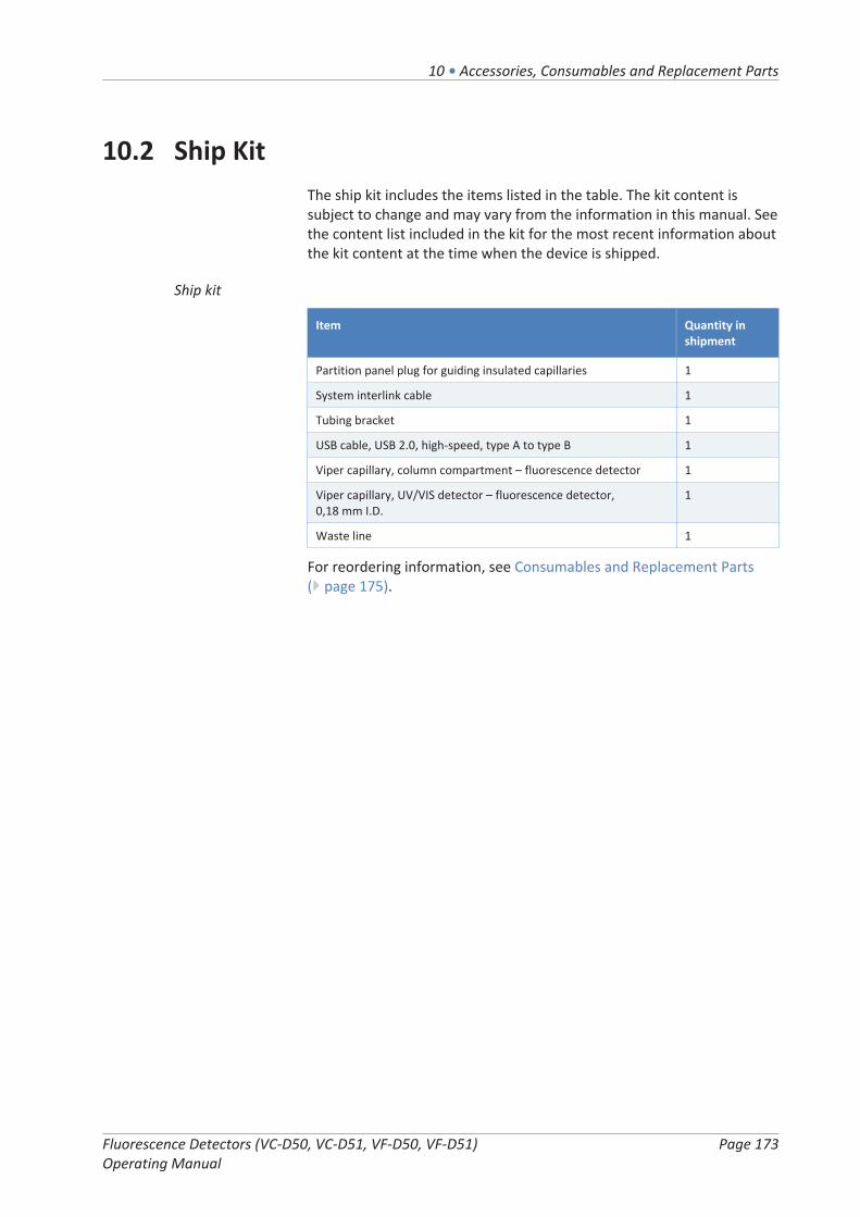
10 • Accessories, Consumables and Replacement Parts
Fluorescence Detectors (VC-D50, VC-D51, VF-D50, VF-D51) Operating Manual
Page 173
10.2 Ship KitThe ship kit includes the items listed in the table. The kit content issubject to change and may vary from the information in this manual. Seethe content list included in the kit for the most recent information aboutthe kit content at the time when the device is shipped.
Ship kit
Item Quantity inshipment
Partition panel plug for guiding insulated capillaries 1
System interlink cable 1
Tubing bracket 1
USB cable, USB 2.0, high-speed, type A to type B 1
Viper capillary, column compartment – fluorescence detector 1
Viper capillary, UV/VIS detector – fluorescence detector, 0,18 mm I.D.
1
Waste line 1
For reordering information, see Consumables and Replacement Parts( page 175).

10 • Accessories, Consumables and Replacement Parts
Page 174 Fluorescence Detectors (VC-D50, VC-D51, VF-D50, VF-D51) Operating Manual
10.3 Optional AccessoriesFlow cells and Flow cells accessories
Item Part No.
Standard flow cell, biocompatible 6079.4230
Micro flow cell, biocompatible 6079.4330
Flushing and injection kit for flow cells, including syringe 6078.4200
Viper capillary, I.D. x length 0.18 x 450 mm, stainless steelFor connecting column and flow cell inlet when usingUltiMate 3000 flow cells.
6040.2365
Overpressure relief valveSuitable to protect the Micro flow cell of the fluorescencedetector against overpressure. The valve opens at a pressure of 4 MPa (40 bar).
6079.9240
TIP UltiMate 3000 fluorescence detector flow cells have the inlet andoutlet on the left side. To connect the column outlet to the left side ofthe flow cell in a Vanquish fluorescence detector, we recommend usingthe capillary of 450 mm length listed in the table above.
Miscellaneous
Item Part No.
DAC boardProvides two analog outputs. Contact Thermo Fisher ScientificTechnical Support for installation.
6083.0900
Dual-PMT optionProvides a second PMT for the near infrared region as an upgrade.Contact Thermo Fisher Scientific Technical Support for installation.
6078.5360

10 • Accessories, Consumables and Replacement Parts
Fluorescence Detectors (VC-D50, VC-D51, VF-D50, VF-D51) Operating Manual
Page 175
10.4 Consumables and Replacement PartsCapillaries and tubing
Description Part No.
Viper capillary, 350 mm length, MP35N, for connection to thecolumn
6042.2340
Viper capillary, 300 mm length, MP35N, for connection from aUV/VIS detector to the fluorescence detector
6042.2322
Waste line 6036.2425
Flow cell plugs for inlet and outlet 6200.5502
For system capillaries, refer to the Vanquish System Operating Manual.
Miscellaneous
Description Part No.
Front door kit, including right door and left door 6083.3018
Fuses kit, Vanquish systemThe kit includes the appropriate fuses for the Vanquish systemmodules. For the detector, use only 3.15 AT, 250 V AC, slowblowfuses.
6036.0002
Packing material for detector with enclosure 6083.0090
Interface cables
Description Part No.
Digital I/O signaling cable, 6-pin, cable length: 5 m 6036.0006
System interlink cable 6036.0004
USB cable, type A to type B, high-speed, USB 2.0Cable length: 0.5 m
6720.8910
USB cable, type A to type B, high-speed, USB 2.0Cable length: 1 m
6035.9035
USB cable, type A to type B, high-speed, USB 2.0Cable length: 5 m
6911.0002
Power cords
Description Part No.
Power cord, Australia 6000.1060
Power cord, China 6000.1080
Power cord, Denmark 6000.1070
Power cord, EU 6000.1000
Power cord, India, SA 6000.1090

10 • Accessories, Consumables and Replacement Parts
Page 176 Fluorescence Detectors (VC-D50, VC-D51, VF-D50, VF-D51) Operating Manual
Description Part No.
Power cord, Italy 6000.1040
Power cord, Japan 6000.1050
Power cord, UK 6000.1020
Power cord, USA 6000.1001
Power cord, Switzerland 6000.1030

11 • Appendix
Fluorescence Detectors (VC-D50, VC-D51, VF-D50, VF-D51) Operating Manual
Page 177
11 AppendixThis chapter provides additional information about compliance,UV cutoff wavelengths, and the use of the digital I/O ports.
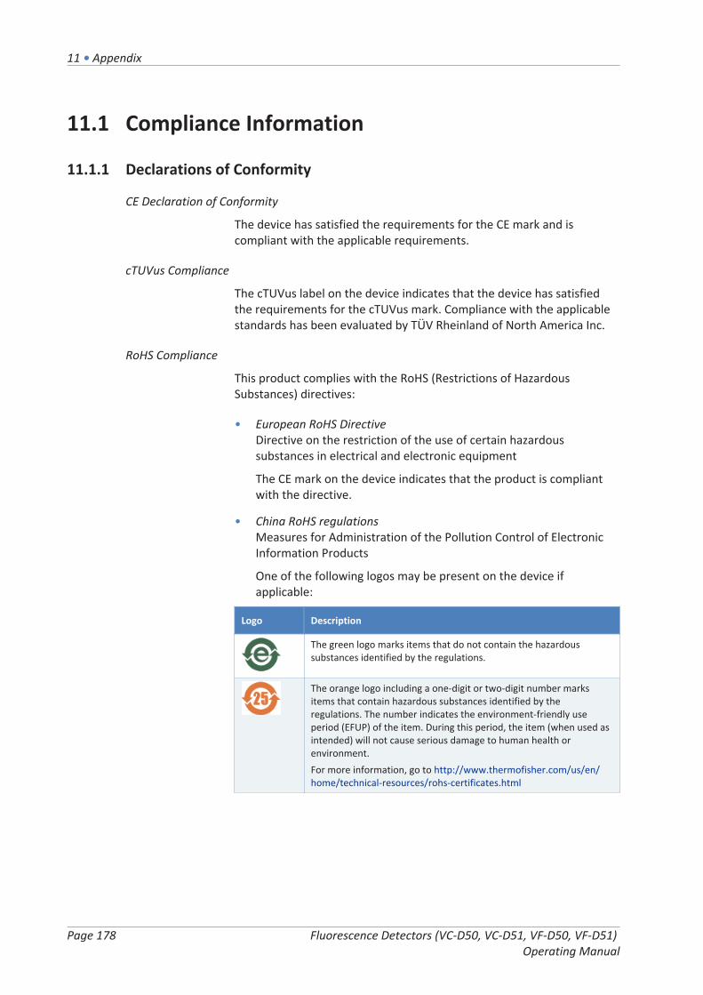
11 • Appendix
Page 178 Fluorescence Detectors (VC-D50, VC-D51, VF-D50, VF-D51) Operating Manual
11.1 Compliance Information
11.1.1 Declarations of Conformity
CE Declaration of Conformity
The device has satisfied the requirements for the CE mark and iscompliant with the applicable requirements.
cTUVus Compliance
The cTUVus label on the device indicates that the device has satisfiedthe requirements for the cTUVus mark. Compliance with the applicablestandards has been evaluated by TÜV Rheinland of North America Inc.
RoHS Compliance
This product complies with the RoHS (Restrictions of HazardousSubstances) directives:
• European RoHS DirectiveDirective on the restriction of the use of certain hazardoussubstances in electrical and electronic equipment
The CE mark on the device indicates that the product is compliantwith the directive.
• China RoHS regulationsMeasures for Administration of the Pollution Control of ElectronicInformation Products
One of the following logos may be present on the device ifapplicable:
Logo Description
The green logo marks items that do not contain the hazardoussubstances identified by the regulations.
The orange logo including a one-digit or two-digit number marksitems that contain hazardous substances identified by theregulations. The number indicates the environment-friendly useperiod (EFUP) of the item. During this period, the item (when used asintended) will not cause serious damage to human health orenvironment.For more information, go to http://www.thermofisher.com/us/en/home/technical-resources/rohs-certificates.html

11 • Appendix
Fluorescence Detectors (VC-D50, VC-D51, VF-D50, VF-D51) Operating Manual
Page 179
11.1.2 WEEE Compliance
This product is required to comply with the European Union’s WasteElectrical & Electronic Equipment (WEEE) Directive. It is marked with thefollowing symbol:
Figure 43: WEEE symbol
Thermo Fisher Scientific has contracted with one or more recycling ordisposal companies in each European Union (EU) Member State, andthese companies should dispose of or recycle this product. For furtherinformation, contact Thermo Fisher Scientific.
11.1.3 FCC Compliance
This equipment has been tested and found to comply with the limits fora Class A digital device, pursuant to part 15 of the U.S. FCC Rules.
These limits are designed to provide reasonable protection againstharmful interference when the equipment is operated in a commercialenvironment. This equipment generates, uses, and can radiate radiofrequency energy and, if not installed and used in accordance with theinstructions, may cause harmful interference to radio communications.Operation of this equipment in a residential area is likely to causeharmful interference, in which case the user will be required to correctthe interference at his expense.
11.1.4 Manual Release History
Revision Covering
2.0 VC-D50, VC-D51, VF-D50, VF-D51
1.2a VF-D50, VF-D51
1.2 VF-D50, VF-D51
1.1 VF-D50, VF-D51
The instructions were prepared in English (original instructions). Otherlanguage versions are translations based on the English originalinstructions.

11 • Appendix
Page 180 Fluorescence Detectors (VC-D50, VC-D51, VF-D50, VF-D51) Operating Manual
11.2 UV Cutoff Wavelengths of SolventsThe UV cutoff wavelength is the minimum effective wavelength for themeasurement. The mobile phase composition affects its UV cutoffwavelength.
In general, mobile phases are solvents, such as, water, acetonitrile,methanol, or other substances. They may also contain salts, such assodium hydroxide (NaOH).
Most solvents have a UV cutoff wavelength within the spectral range ofthe device. For optimum measurement results, perform quantitativemeasurements at a wavelength that is sufficiently above the UV cutoffwavelength. The UV cutoff wavelength also depends on the quality ofthe solvent. For information about the UV cutoff wavelength for asolvent, contact the manufacturer of the solvent.
The refractive index of different solvents can differ. Therefore, changingthe mobile phase composition can lead to baseline fluctuations.

11 • Appendix
Fluorescence Detectors (VC-D50, VC-D51, VF-D50, VF-D51) Operating Manual
Page 181
11.3 Digital I/OThe digital I/O ports (Dig I/O) can be used to exchange digital signalswith external devices. Each port provides:
• one digital input
• one relay output
Pin Assignment
Figure 44: Digital I/O port
Pin Description
1 Not used
2 Relay output — Relay_NC (Normally Closed contact)
3 Ground — GND
4 Digital input — Input
5 Relay output — Relay_COMCOM is the common contact for NO and NC. If the relay is not activated or ifthe device is turned off, the connection is between COM and NC. If the relayis activated, the connection is between COM and NO.
6 Relay output — Relay_NO (Normally Open contact)
The next table lists the functions assigned to the connector pins and thecolor of the cable wire connected to each pin.
Pin Wire Color Signal Name Signal Level Remarks
1 Pink Not used
2 Gray Relay output— Relay_NC
Potential free0-24 V, 0-100 mA
Opening contact
3 Green Ground —GND
Ground Reference potential

11 • Appendix
Page 182 Fluorescence Detectors (VC-D50, VC-D51, VF-D50, VF-D51) Operating Manual
Pin Wire Color Signal Name Signal Level Remarks
4 Yellow Digital input —Input
Input (low active):On: 0-0.4 VOff: 2.2-5 VPull-up resistor: 47 kΩ to 5 V
Digital input; reference potential isground. Note the following:• The maximum input voltage at the
input must not exceed +5 V withreference to ground.
• The minimum input voltage mustnot be lower than the groundpotential.
5 White Relay output— Relay_COM
Potential free Common contact for NO and NC
6 Brown Relay output— Relay_NO
Potential free0-24 V, 0-100 mA
Closing contact
Prerequisites
To use the digital I/O functionality, the following prerequisites must befulfilled:
• The digital I/O port must be connected to the external device withthe digital I/O signaling cable (part no. 6036.0006).
• The inputs and outputs that you want to use must be selected in theInstrument Configuration Manager.
Connecting a Digital I/O Port
1. Plug the 6-pin connector of the cable into the digital I/O port thatyou want to use.
2. For each relay output or digital input to be used, connect theappropriate signal wire and ground wire to the correspondingconnectors on the external device. For details, refer to thedocumentation provided with the external device.
Selecting the inputs and outputs in the Chromeleon software
1. In the dialog box for the device, on the Inputs and Outputs pages,select the inputs and outputs that you want to use. The numberingin the dialog box corresponds to the numbers on the port.

Index
Fluorescence Detectors (VC-D50, VC-D51, VF-D50, VF-D51) Operating Manual
Page 183
IndexA
accessories ............................................... 46, 171optional ..................................................... 174ship kit ....................................................... 173
additional detector operating issues.............. 163additives ........................................................... 27
information ................................................. 27audit trail ........................................................ 156Audit Trail messages ...................................... 158autozero ......................................................... 117
Bbaseline behavior ................................... 107, 117baseline noise................................................. 107baseline spectrum .......................................... 101buffers .............................................................. 27
concentration.............................................. 27information ................................................. 27
Ccalibration ...................................................... 132capillaries
guide ........................................................... 65install ........................................................... 69Viper............................................................ 69
CE mark .......................................................... 178chloride concentration ..................................... 28Chromeleon...................................................... 41
audit trail................................................... 156device setup ................................................ 87module setup .............................................. 87multiple channels ...................................... 100parameters................................................ 104Predictive Performance............................. 130set wavelengths ........................................ 108Smart Shutdown........................................ 118Smart Standby........................................... 118Smart Startup .............................................. 97
cleaning .......................................................... 128condensation.............................................. 52, 61connectors........................................................ 57consumables .......................................... 171, 175cTUVus mark .................................................. 178cutoff filter ..................................................... 112
Ddata collection rate ................................ 107, 114
guidelines .................................................. 114decontamination.................................... 128, 129delivery............................................................. 46detector
additional operating issues ....................... 163sensitivity .................................................. 108
detector waste line .......................................... 75determine wavelengths ................................. 107device
optimization .............................................. 106preparing for operation .............................. 96restart after long-term shutdown ............. 121shutdown .................................................. 118
Dig I/O ...................................................... 58, 181Digital I/O ................................................. 58, 181disk space ....................................................... 107door.................................................................. 53
open ............................................................ 53remove ...................................................... 124replace....................................................... 144unhinge ............................................. 124, 144
drain system..................................................... 76drainage ........................................................... 76
Eemission scan ................................................. 102emission wavelength...................................... 107equilibration..................................................... 96excitation scan ............................................... 101excitation wavelength .................................... 107
FFCC ................................................................. 179features overview ............................................ 32filter wheel ............................................. 107, 112firmware update ............................................ 142FL Field Acquisition......................................... 102flow cell ............................................................ 37
backpressure determination....................... 77clean.......................................................... 138connect inlet ............................................... 72connect outlet ............................................. 75

Index
Page 184 Fluorescence Detectors (VC-D50, VC-D51, VF-D50, VF-D51) Operating Manual
exchange ........................................... 136, 139flow connections ......................................... 71guidelines .................................................... 98handling .................................................... 136identification chip ....................................... 37initial installation......................................... 61install ......................................................... 139remove ...................................................... 136temperature control ................................... 38types............................................................ 38
flow cell temperature............................. 107, 115fluorescence intensity .................................... 107fuses ............................................................... 140
Ggloves ............................................................... 23guide hole......................................................... 65guidelines
flow cell handling ........................................ 98flow cell maintenance ............................... 136installation................................................... 48maintenance ............................................. 125operation..................................................... 91
HHighPower mode............................................ 116
Iidentification chip ............................................ 37
flow cell ....................................................... 37INIT button ....................................................... 93Initialize .......................................................... 105inlet capillary .................................................... 72install slide-in module .................................... 151installation........................................................ 47
capillaries and tubing .................................. 65safety guidelines ......................................... 48site requirements........................................ 51system ......................................................... 49
intended use..................................................... 20interior view ..................................................... 36Interlink ............................................................ 57
Kkeypad.............................................................. 92
Llamp ......................................................... 39, 131
lamp mode ................................................ 115replace....................................................... 131
lamp age......................................................... 131lamp lifetime .................................................. 131lamp mode ..................................................... 107leak detection........................................... 40, 105leak sensor ..................................................... 162leak sensor mode ........................................... 105leakage ........................................................... 162LED bar ............................................... 92, 93, 156limit of detection............................................ 107liquid leaks...................................................... 162LongLife mode................................................ 116long-term shutdown ...................................... 119
Mmain power fuses ........................................... 140maintenance .......................................... 123, 128
cleaning ..................................................... 128decontaminating ....................................... 128doors ......................................................... 144firmware update ....................................... 142flow cells ................................................... 136fuses .......................................................... 140general rules.............................................. 127interval ...................................................... 128introduction .............................................. 124lamp .......................................................... 131predictive performance............................. 130safety guidelines ....................................... 125wavelength calibration.............................. 132wavelength validation............................... 134wellness..................................................... 130
MaxPMTSaturation ........................................ 110messages ........................................................ 158method development .................................... 106move ................................................................ 50multi-channel mode ......................................... 99Multi-Channel Performance........................... 100multiple wavelength................................. 99, 100Mute Alarm ...................................................... 92
NNot initialized ................................................. 132

Index
Fluorescence Detectors (VC-D50, VC-D51, VF-D50, VF-D51) Operating Manual
Page 185
Ooperating issues ............................................. 162operating principle ........................................... 33operation.................................................... 41, 89
control elements ......................................... 92flow cells ..................................................... 98important parameters............................... 104interrupt.................................................... 118power on/off ............................................... 95safety guidelines ......................................... 91
operational modes ........................................... 99optimization ................................................... 106
data collection rate ................................... 114guidelines .................................................. 106parameters overview ................................ 107
optimum wavelength ..................................... 107outlet waste line............................................... 75overview (functional) ....................................... 31
Ppeak resolution .............................................. 107peak width...................................................... 107permitted wavelength range for emission..... 107pH range........................................................... 27PMT ........................................................ 107, 113power considerations................................. 51, 52power cord ....................................................... 51power on/off .................................................... 95power up .......................................................... 86Predictive Performance.................................. 130preparation
remove module......................................... 149protective clothing ........................................... 22
Rrating plate ....................................................... 19regulatory compliance ..................................... 29remove slide-in module ................................. 149reordering ...................................................... 171replacement parts .................................. 171, 175reproducibility ................................................ 107response time......................................... 107, 114restart device after long-term shutdown....... 121RoHS mark...................................................... 178
Ssafety class ....................................................... 21safety glasses.................................................... 22safety guidelines
case of emergency ...................................... 26electrical safety ........................................... 23general ........................................................ 21general hazards ........................................... 23installation................................................... 48maintenance ............................................. 125operation..................................................... 91power cord.................................................. 51protective equipment ................................. 22qualification of personnel ........................... 21servicing .................................................... 125
safety symbols............................................ 18, 19scans
FL Field Acquisition.................................... 102single spectrum ......................................... 101
second PMT.................................................... 113selectivity ....................................................... 107sensitivity ............................................... 107, 108service ............................................................ 123settings ........................................................... 104setup
hardware..................................................... 54software ...................................................... 87system arrangement ................................... 54
ship................................................................. 146ship kit ...................................................... 46, 173short-term shutdown ..................................... 118shutdown ....................................................... 118
long-term .................................................. 119short-term................................................. 118
signal words ..................................................... 18Single Spectrum Scan ..................................... 101single-channel mode ........................................ 99site requirements ............................................. 51
condensation......................................... 52, 61power considerations............................ 51, 52power cord.................................................. 51
slide-in module............................................... 149install ......................................................... 151remove ...................................................... 149return ........................................................ 150
Smart Shutdown............................................. 118Smart Standby ................................................ 118Smart Startup ................................................... 97

Index
Page 186 Fluorescence Detectors (VC-D50, VC-D51, VF-D50, VF-D51) Operating Manual
solventchloride concentration................................ 28information ................................................. 27pH range...................................................... 27
specifications.................................................. 165performance (detector) ............................ 166performance (flow cells) ........................... 168physical...................................................... 169
spectrum scans............................................... 101Standard lamp mode...................................... 116startup.............................................................. 96status indicator
LED bar .......................................... 92, 93, 156STATUS LED ................................... 92, 93, 156
STATUS LED ........................................ 92, 93, 156synchronous scan ........................................... 102system arrangement ........................................ 54system equilibration......................................... 96System Interlink................................................ 57
Ttemperature control ........................................ 38transport ........................................................ 146troubleshooting.............................................. 155
general information .................................. 156messages................................................... 158operating issues ........................................ 162
tubing ............................................................... 69tubing bracket .................................................. 65tubing chase ..................................................... 65tubing guides.................................................... 65type label.......................................................... 19
UUniversal Serial Bus .......................................... 58unpack.............................................................. 44USB ................................................................... 58UV cutoff wavelengths ................................... 180
VViper fitting system .......................................... 69
Wwaste line ......................................................... 75wavelength calibration................................... 132wavelength switching..................................... 108
wavelength validation .................................... 134WEEE .............................................................. 179
ZZero Order Mode ........................................... 100

Index
Fluorescence Detectors (VC-D50, VC-D51, VF-D50, VF-D51) Operating Manual
Page 187

Thermo Fisher Scientific Inc.168 Third AvenueWalthamMassachusetts 02451USA
www.thermofisher.com


