Instruction Manual andExperiment Guide for thePASCO scientificModel CI-6728
012-06619A
10/97
FLUORIDE ION SELECTIVEELECTRODE
Fluoride Ion Selective Electrode 012–06619A
Always use eye protection
and gloves when working
with chemicals.
012–06619A Fluoride Ion Selective Electrode
Table of ContentsIntroduction......................................................................................................................................... 1
Theory .................................................................................................................................................. 1
Measurement Procedure .................................................................................................................... 6Direct Measurement of Fluoride ................................................................................................... 6Direct Measurement of Fluoride in Water .................................................................................... 7Direct Measurement of Fluoride in Acid Solutions ...................................................................... 8Direct Measurement of Fluoride in Alkaline Solutions ................................................................ 8Low Level Fluoride Determination .............................................................................................. 8Titration ........................................................................................................................................ 9Titration Procedure for Fluoride Determination ......................................................................... 10
Technical Support ............................................................................................................................. 19
i
ii
Equipment Return
Should the product have to be returned to PASCOscientific for any reason, notify PASCO scientific byletter, phone, or fax BEFORE returning the product.Upon notification, the return authorization andshipping instructions will be promptly issued.
ä NOTE: NO EQUIPMENT WILL BEACCEPTED FOR RETURN WITHOUT ANAUTHORIZATION FROM PASCO.
When returning equipment for repair, the units mustbe packed properly. Carriers will not acceptresponsibility for damage caused by improperpacking. To be certain the unit will not be damaged inshipment, observe the following rules:
➀ The packing carton must be strong enough for theitem shipped.
➁ Make certain there are at least two inches of packingmaterial between any point on the apparatus and theinside walls of the carton.
➂ Make certain that the packing material cannot shift inthe box or become compressed, allowing theinstrument come in contact with the packing carton.
Address: PASCO scientific10101 Foothills Blvd.P.O. Box 619011Roseville, CA 95678-9011
The PASCO scientific 012-06619A manual iscopyrighted and all rights reserved. However,permission is granted to non-profit educationalinstitutions for reproduction of any part of theFluoride Ion Selective Electrode manual providing thereproductions are used only for their laboratories andare not sold for profit. Reproduction under any othercircumstances, without the written consent of PASCOscientific, is prohibited.
Limited Warranty
PASCO scientific warrants the product to be free fromdefects in materials and workmanship for a period ofone year from the date of shipment to the customer.PASCO will repair or replace at its option any part ofthe product which is deemed to be defective inmaterial or workmanship. The warranty does notcover damage to the product caused by abuse orimproper use. Determination of whether a productfailure is the result of a manufacturing defect orimproper use by the customer shall be made solely byPASCO scientific. Responsibility for the return ofequipment for warranty repair belongs to thecustomer. Equipment must be properly packed toprevent damage and shipped postage or freightprepaid. (Damage caused by improper packing of theequipment for return shipment will not be covered bythe warranty.) Shipping costs for returning theequipment after repair will be paid by PASCOscientific.
Copyright, Warranty, and Equipment Return
Please�Feel free to duplicate this manualsubject to the copyright restrictions below.
CreditsAuthor: Peter BoyleEditor: Steve Miller
012–06619A Fluoride Ion Selective Electrode
1
IntroductionThe PASCO scientific Fluoride Ion Selective Electrode is used to quickly, simply, accurately, and economicallymeasure fluoride ions in aqueous solutions.
TheoryThe PASCO scientific Fluoride Ion Selective Electrode consists of a single crystal of lanthanum fluoride as themembrane, bonded into a glass or an epoxy body. Only fluoride ions are mobile in the ionic conductor crystal. Whenthe membrane comes in contact with a solution containing fluoride ions, a potential develops across the membrane.This electrode potential is measured against a constant reference potential, using an ISE Amplifier and aScienceWorkshop computer interface, and depends on the level of free fluoride ions in the solution. The Nernstequation describes the level of fluoride ions in the solution corresponding to the measured potential:
E = E0 – S log X
where:
E = measured electrode potential
E0 = reference potential (a constant)
S = electrode slope ( ≈ 57 mVdecade
)
X = level of fluoride ions in solution
The activity, X, represents the effective concentration of free fluoride ions in the solution. Total fluorideconcentration, Ct, may include some bound as well as free fluoride ions. Since the electrode only responds to freeions, the concentration of the free ions, Cƒ, is found by:
Cf = Ct – Cb
where Cb represents the concentration of all bound or complexed fluoride ions.
The activity is related to the free ion concentration, Cƒ, by the activity coefficient, γ, by:
X = γCf
Activity coefficients vary, depending on total ionic strength, I, defined as:
I = 12
ΣCXZX2
where:
CX = concentrationof ion X
ZX = charge of ion XΣ = sum of all of the types of ions in the solution
Fluoride Ion Selective Electrode 012–06619A
2
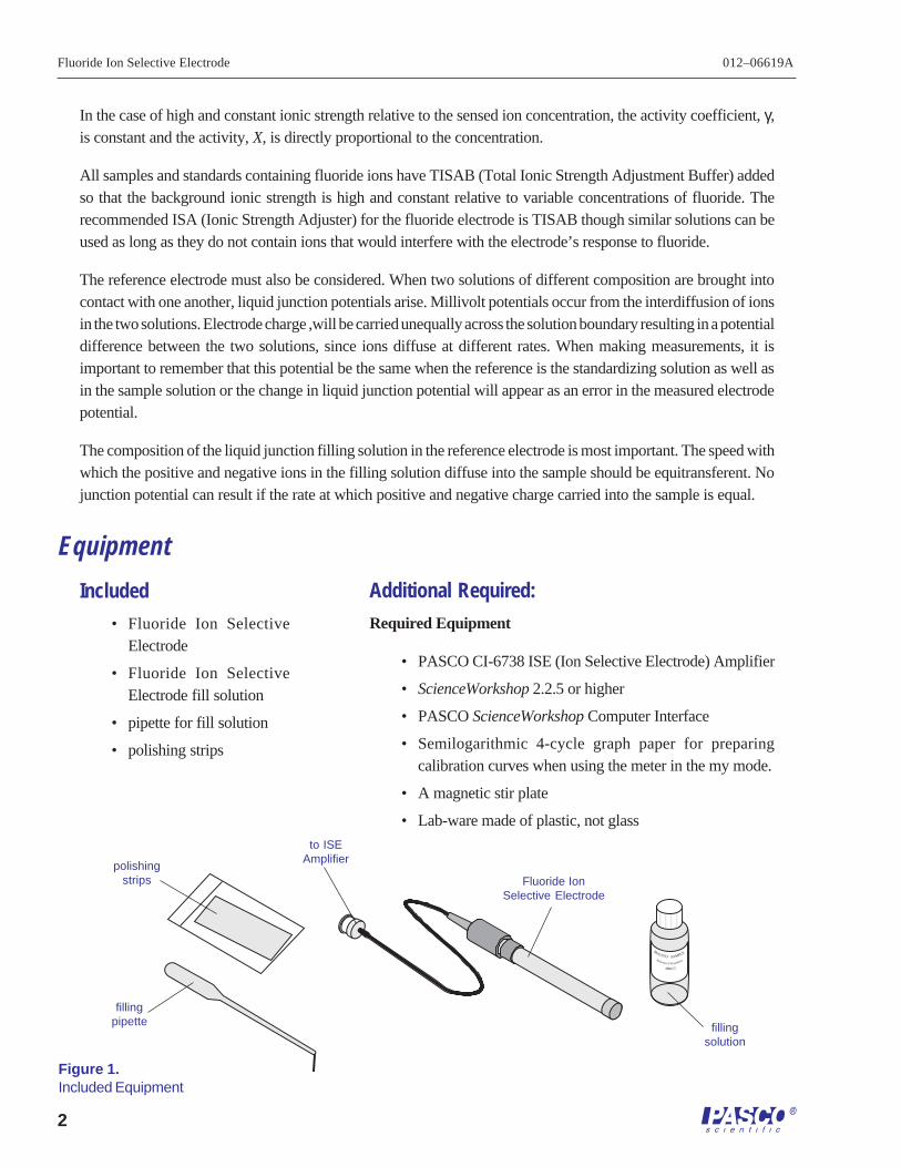
Additional Required:
Required Equipment
• PASCO CI-6738 ISE (Ion Selective Electrode) Amplifier
• ScienceWorkshop 2.2.5 or higher
• PASCO ScienceWorkshop Computer Interface
• Semilogarithmic 4-cycle graph paper for preparingcalibration curves when using the meter in the my mode.
• A magnetic stir plate
• Lab-ware made of plastic, not glass
ROO1013 SAMPLE
4MKCI
Reference Fill Solution
In the case of high and constant ionic strength relative to the sensed ion concentration, the activity coefficient, γ,is constant and the activity, X, is directly proportional to the concentration.
All samples and standards containing fluoride ions have TISAB (Total Ionic Strength Adjustment Buffer) addedso that the background ionic strength is high and constant relative to variable concentrations of fluoride. Therecommended ISA (Ionic Strength Adjuster) for the fluoride electrode is TISAB though similar solutions can beused as long as they do not contain ions that would interfere with the electrode’s response to fluoride.
The reference electrode must also be considered. When two solutions of different composition are brought intocontact with one another, liquid junction potentials arise. Millivolt potentials occur from the interdiffusion of ionsin the two solutions. Electrode charge ,will be carried unequally across the solution boundary resulting in a potentialdifference between the two solutions, since ions diffuse at different rates. When making measurements, it isimportant to remember that this potential be the same when the reference is the standardizing solution as well asin the sample solution or the change in liquid junction potential will appear as an error in the measured electrodepotential.
The composition of the liquid junction filling solution in the reference electrode is most important. The speed withwhich the positive and negative ions in the filling solution diffuse into the sample should be equitransferent. Nojunction potential can result if the rate at which positive and negative charge carried into the sample is equal.
Equipment
Figure 1.Included Equipment
to ISEAmplifier
Fluoride IonSelective Electrode
fillingpipette filling
solution
polishingstrips
Included
• Fluoride Ion SelectiveElectrode
• Fluoride Ion SelectiveElectrode fill solution
• pipette for fill solution
• polishing strips
012–06619A Fluoride Ion Selective Electrode
3
Required Solutions
The stock solutions described in this section may be created as described in the text or ordered directly from PASCO.The solutions available for order, and their respective prices are listed on the ‘ISE Working Solution Price List’.
• Deionized or distilled water for solution and standard preparation.
• Fluoride Standard Solution, 0.1 M NaF
To prepare this solution, half fill a one liter volumetric flask with distilled water and add 4.2 grams ofreagent-grade sodium fluoride. Swirl the flask gently to dissolve the solid. Fill the flask to the mark withdistilled water, cap, and upend several times to mix the solution.
• Fluoride Standard, 1000 ppm F-1
To prepare this solution, half fill a one liter volumetric flask with distilled water and add 2.21 grams ofreagent-grade sodium fluoride. Swirl the flask gently to dissolve the solid. Fill the flask to the mark withdistilled water, cap, and upend several times to mix the solution.
• Fluoride Standard, 100 ppm F-1
To prepare this solution, half fill a one liter volumetric flask with distilled water and add 0.22 grams ofreagent-grade sodium fluoride. Swirl the flask gently to dissolve the solid. Fill the flask to the mark withdistilled water, cap, and upend several times to mix the solution.
• Total Ionic Strength Adjuster Buffer, TISAB 1
TISAB 1 is used to adjust the pH of the solution, de-complex fluoride and provide a constant backgroundionic strength. To prepare this solution, half fill a four liter beaker with distilled water, place the beaker ona magnetic stirrer, add a large stirring bar, and begin stirring. Slowly add 230 ml of concentrated acetic acid,232 grams of reagent-grade sodium chloride, and 16 grams of reagent-grade CDTA. After the solids havedissolved, allow the solution to cool to room temperature. Slowly add 150 grams of reagent-grade sodiumhydroxide. After the solids have dissolved, allow the solution to cool to room temperature. Calibrate a pHelectrode and adjust the pH to 5.25 with small addition of 5 M NaOH. Fill to the mark with distilled water.
• Low Level Total Ionic Strength Adjuster Buffer, TISAB 2
Use when measuring in samples containing less than 2X10⁻⁵ M (0.4 ppm) fluoride and containing nofluoride complexing agents. To prepare this solution, place about 2000 ml distilled water in a four literbeaker. Add 57 ml glacial acetic acid and 55 grams sodium chloride. Place the beaker on a magnetic stirrer,add a stirring bar and begin stirring. Immerse a calibrated pH electrode into the solution. Slowly add 5 MNaOH until the pH is 5.25. Allow the solution to cool and fill to the mark with distilled water.
• Total Ionic Strength Adjuster Buffer, TISAB 3
TISAB 3 will complex more than 100 ppm of aluminum or iron in the presence of 1 ppm fluoride ion. Therewill be an error of approximately 5% in the measurement of 1 ppm fluoride in the presence of 200 ppmaluminum or iron. To prepare this solution, add about 2000 ml of distilled water to a four liter beaker. Placethe beaker on a magnetic stirrer, add a large stirring magnet, and begin stirring. Slowly add 336 ml ofconcentrated HCl (36 - 38%), 968 grams of TRIS (hydroxymethylaminomethane) and 920 grams ofsodium tartrate (Na2C4H4O6 2H2O). After the solid has dissolved, allow the solution to cool to roomtemperature. Fill to the mark with distilled water.
Fluoride Ion Selective Electrode 012–06619A
4
General Preparation
Electrode Preparation
1. Remove the rubber cap covering the electrode tip and the rubberinsert covering the filling hole of the reference electrode. Fill thecombination electrode or the reference electrode with the fillingsolution shipped with the electrode to a level just below the fill hole.
2. Connect the Fluoride Ion Selective Electrode to the ISE Amplifierand insert the DIN connector of the ISE Amplifier into analog channelA or B on a PASCO Computer Interface (Figures 2a and 2b).
Electrode Slope Check Using ScienceWorkshop(check electrodes each day)
1. To a 150 ml plastic beaker, add 50 ml of distilled water and 50 ml ofTISAB. Place the beaker on a magnetic stirrer and begin stirring at aconstant rate. Start the ScienceWorkshop software, select the IonSelective Electrode sensor, open a Digital display, change the numberof digits to the right of the decimal from 1 to 3, and begin monitoringdata. Lower the electrode tip into the solution.
2. Using a pipette, add 1 ml of 0.1 M, 1000 ppm, or 100 ppm fluoridestandard to the beaker. When the reading has stabilized, record theVoltage reading in the Digits display.
3. Using a pipette, add 10 ml of the same fluoride standard used aboveto the beaker. When the reading has stabilized, record the Voltagereading in the Digits display.
4. Determine the difference between the two readings. The electrode isoperating correctly if the potential has changed by 57±2mV, assumingthe solution temperature is between 20 °C and 25 °C. See theTroubleshooting section if the potential change is not within thisrange.
➤ Note: Slope is defined as the change in potential observedwhen the concentration changes by a factor of 10.
Figure 2Equipment Setup. a: filling the electrodewith filling solution; b & c : connecting theelectrode to the ISE Amplifier and to thecomputer interface
b
c Rotate ringone-quarterturn to secure
electrodeconnector
ISE Amplifier
Insert DINconnector intoanalog channelA or B .
a
fill hole
rubbersleeve
rubber cap
012–06619A Fluoride Ion Selective Electrode
5
Measurement
Measuring Hints
• All samples and standards should be at the same temperature for precise measurement. A difference of l °Cin temperature will result in a 2% measurement error.
• Constant, but not violent, stirring is necessary for accurate measurement. Magnetic stirrers can generatesufficient heat to change the solution temperature. To counteract this effect, place a piece of insulatingmaterial, such as a styrofoam sheet, between the stirrer and the beaker.
• Always rinse the electrodes with distilled water and blot dry between measurements. Use a clean, dry tissueto prevent cross-contamination.
• For samples with high ionic strength, prepare standards whose composition is similar to the sample.
• Always check to see that the membrane is free from air bubbles after immersion into standard or sample.
Sample Requirements
• All samples must be aqueous and not contain organics which can dissolve the epoxy electrode body and/or the cement bonding the sensing crystal to the electrode body. Inorganic solutions will not effect theelectrode. Infrequent measurements in solutions containing methanol, acetone, or dioxane are permitted.Highly polar solvents, such as CHC13 or DMF, should not be contained in the samples.
• The addition of TISAB to samples and standards will adjust the pH to 5.0 - 5.5. Samples must be above pH5 to avoid forming complexes with hydrogen ions and below pH 7 to avoid interference by hydroxide ions.
• The temperature of the standard solutions and of the sample solutions should be the same and below 80 °C.
• The use of TISAB 1 also preferentially forms complexes with aluminum and with iron, breaking thecomplexes that fluoride forms with these ions. With 1 ppm fluoride present, up to 3 - 5 ppm aluminum oriron is complexed. If higher levels of aluminum or iron are present, use TISAB 3.
Units of Measurement
Fluoride concentrations are measured in units of ppm as fluoride, moles per liter, or any other convenientconcentration unit. Table 1 indicates some concentration units and conversion factors.
TABLE 1: Concentration Unit Conversion Factors
ppm F-1 moles/liter
190.00 1.0 X 10⁻² M19.00 1.0 X 10⁻³ M1.90 1.0 X 10⁻⁴ M
Fluoride Ion Selective Electrode 012–06619A
6
Measurement Procedure
Direct Measurement
Direct measurement is a simple procedure for measuring a large number of samples. A single reading is all that isrequired for each sample. The ionic strength of samples and standards should be made the same by adjustment withTISAB for all fluoride solutions. The temperature of both sample solution and standard solution should be madethe same.
Direct Measurement of Fluoride
äNote: A calibration curve is constructed on semilogarithmic paper. The measuredelectrode potential (linear axis) is plotted against the standard concentration (log axis). Inthe linear region of the curve, only two standards are necessary to determine a calibrationcurve. Calibration solutions close to the anticipated value of the “unknown” should bechosen. In the nonlinear region, additional points must be measured. The directmeasurement procedures given are for the linear portion of the curve. The nonlinearportion of the curve requires the use of low level procedures.
1. By serial dilution, prepare three standard solutions from the 0.l M, 1000 ppm, or the 100 ppm stockstandard. The resultant concentrations should be l0-2 M, l0-3 M, and l0-4 M or 100, 10, and 1 ppm. Add50 ml of TISAB 1 or TISAB 3 to each 50 ml of standard. When Calibrating, assume that the added TISABhas no effect on the standard concentration.
2. Place the most dilute solution on the magnetic stirrer and begin stirring at a constant rate. After assuringthat ScienceWorkshop is operating, lower the electrode tip into the solution. When the reading hasstabilized, record the voltage reading indicated in the Digits display.
3. Place the mid-range solution on the magnetic stirrer and begin stirring. After rinsing the electrodes withdistilled water, blot dry, and immerse the electrodes in the solution. When the reading has stabilized,record the voltage reading indicated in the Digits display.
4. Place the most concentrated solution on the magnetic stirrer and begin stirring. After rinsing theelectrodes with distilled water, blot dry, and immerse the electrodes in the solution. When the readinghas stabilized, record the voltage reading indicated in the Digits display.
5. Using the semilogarithmic graph paper, plot the voltage reading (linear axis) against the concentration.(log axis). Extrapolate the curve down to about 1.0Xl0-5 M. A typical calibration curve can be found inFigure 3.
012–06619A Fluoride Ion Selective Electrode
7
6. To a clean, dry, 150 ml plastic beaker, add 50 ml of sample and 50 ml of TISAB 1 or TISAB 3. Placethe beaker on the magnetic stirrer and begin stirring. Rinse the electrodes with distilled water, blot dry,and lower the electrode tip into the solution. When the reading has stabilized, record the Voltage readingin the Digits display. Using the calibration curve, determine the sample concentration.
7. The calibration should be checked every 1 - 2 hours. Assuming no change in ambient temperature, placethe electrode tip in the mid-range standard. After the reading has stabilized, compare it to the originalreading recorded in Step 3 above. A reading differing by more than 0.5 mV or a change in the ambienttemperature will necessitate the repetition of Steps 2 - 5 above. A new calibration curve should beprepared daily.
Direct Measurement of Fluoride in Water (ASTM D1179, Method B)
The procedure is used to determine total fluoride concentration in water in ppm. TISAB is added to standards andto samples in order to break fluoride complexes of iron and aluminum, adjust the pH, and provide a constant ionicstrength. Fluoride sample concentration is determined, using this method, independent of the level or nature ofdissolved minerals.
1. Prepare 2, 1, and 0.5 ppm fluoride standards by serial dilution of the 100 ppm fluoride standard.
2. To each 50 ml of standard, add 50 ml of TISAB 1 or TISAB 3.
3. Calibrate the meter as previously described by using the 2, 1, and 0.5 ppm standards. The calibration curveshould be drawn on semi-logarithmic 2-cycle graph paper or ScienceWorkshop.
Direct Measurement of Fluoride in Acid Solutions
Hydrogen ion complexes a portion of the fluoride ion in solutions with a pH below 5, forming HF or HF2-1, which
cannot be detected by the electrodes. Adjustment to weakly acidic/weakly basic range before making the fluoridedetermination is necessary, but not with strongly basic solutions. The use of sodium acetate buffers the pH above5 and helps fix the total ionic strength of standards and samples to the same level.
-140
10-5 10-4 10-2 10-1
0.1 1 10(ppm)
100
-100
-60
-20
+20
+60
1,000
~57 mV
10-3
-180
10-fold change
electrodepotential(mV)
F- concentration (M)Figure 3Typical Fluoride Ion Selective Electrode calibration curve
Fluoride Ion Selective Electrode 012–06619A
8
1. Dissolve reagent grade sodium acetate (CH3COONa) in distilled water to prepare a 15% solution. Preparea sufficient quantity to dilute all standards and samples.
2. Prepare a blank solution containing all components of the sample except fluoride. This solution will beused to prepare standards.
3. Add fluoride to the blank solution to prepare standards in the concentration range of the unknownsolutions. Prepare three standards and a calibration curve as previously described. Add 9 parts of sodiumacetate to each 1 part of standard. Fresh standards should be prepared every two weeks if the standardcontains less than 10 ppm fluoride.
4. Calibrate the electrodes as described in the section Electrode Slope Check.
5. After diluting each unknown sample 10:1 with sodium acetate (as in step 3 above), measure the electrodepotential and determine the fluoride concentration.
Direct Measurement of Fluoride in Alkaline Solutions
Hydroxide ions interfere with fluoride measurements in basic solutions with a low fluoride content. At a fluorideconcentration less than 1.0Xl0-4 M and at a pH of 9.5 or above, the electrode potential reading, caused by theconcentration of both hydroxide and fluoride ions, is higher than it would be if fluoride alone were present. (Seesection entitled pH Effects.)
Using a 4 M buffered potassium acetate solution to adjust the pH to between 5 and 6 eliminates hydroxide ion errorand raises the total ionic strength of both standards and samples to the same value. The fluoride ion concentrationcan be determined in the usual manner after both standards and samples are diluted 10:1 with the buffer solution.
1. To prepare a 4 M buffered potassium acetate solution, add one part of distilled water, slowly, to two parts of 6 Macetic acid, CH3COOH, in a large beaker surrounded by a water bath. Slowly add 50% KOH solution to the aceticacid mixture, with constant stirring, until a pH of 5 is reached. Prepare enough buffer to dilute all standards andsamples 10:1.
2. Following the directions given in the preceding section (Determination of Fluoride in Acid Solutions), preparestandards, calibrate the electrodes and measure the unknown samples.
Low Level Fluoride Determination
Use the following low level fluoride measurement procedure in the non-linear portion of the calibration curve. (SeeFigure 1.) This procedure is used for fluoride samples containing less than 2Xl0-5 M or 0.4 ppm fluoride andcontaining no fluoride complexing agents. Use low level TISAB 2 for both samples and standards. A longerresponse time should be expected for low level fluoride measurements.
1. By serial dilution, prepare a l.0Xl0-3 M or 10 ppm fluoride standard by diluting the 0.1 M, 1000 ppm, or 100ppm standard solution. Add 50 ml low level TISAB 2 to 50 ml of standard solution.
2. Using a 150 ml beaker, add 50 ml of distilled water and 50 ml of low level TISAB 2. Place the beaker on themagnetic stirrer and begin stirring at a constant rate. Lower the electrode tip into the solution. Start theScienceWorkshop software, select the Ion Selective Electrode sensor, open a Digital display, and begin monitoringdata.
012–06619A Fluoride Ion Selective Electrode
9
3. Increments of the standard should be added to the beaker according to the steps outlined in Table 2 below. Afterthe reading stabilizes, record the Voltage reading in the Digits display after each addition.
TABLE 2: Low Level Measurement Calibration Curve
Added ConcentrationStep Pipette Volume (ml) ppm M
1 A 0.1 0.01 l.0 X l0-6
2 A 0.1 0.02 2.0 X l0-6
3 A 0.2 0.04 4.0 X l0-6
4 A 0.2 0.06 6.0 X l0-6
5 A 0.4 0.10 1.0 X 10⁻⁵
6 B 2.0 0.29 2.9 X l0-5
7 B 2.0 0.48 4.8 X l0-5
Pipette A = 1 ml graduated pipettePipette B = 2 ml pipetteSolutions: additions of standard/TISAB 2 to 50 ml of distilled water and 50 ml of low level TISAB 2.
4. On semi-logarithmic graph paper, plot the concentration (log axis) against the millivolt reading (linear axis) asin Figure 1. Keep the final solution for checking the electrode calibration.
5. To a 150 ml plastic beaker, add 50 ml of sample and 50 ml of low level TISAB 2. Place the beaker on a magneticstirrer and begin stirring. After rinsing the electrode and blotting dry, place the electrode tip into the solution. Afterstabilization of the reading, read the electrode potential and determine the concentration from the calibration curve.A new low level calibration curve should be prepared daily using fresh standards.
Titration
Titration is a very accurate determination of fluoride. The PASCO Fluoride Ion Selective Electrode can be used asa highly sensitive endpoint detector for titrations of a fluoride-containing sample. Though titrations are more timeconsuming than direct ion measurements, the results are more accurate and reproducible. Titrations accurate to±0.2% of the total fluoride concentration of the sample can be performed using lanthanum nitrate as the titrant. Totalfluoride concentration should be at least l.0Xl0-3 M for endpoint detection. Low results are given if aluminum, iron,or trivalent chromium are present at a level of 1% or higher.
Special titration procedures for aluminum, lithium, lanthanum, and thorium also makes use of the fluoride electrodeas an endpoint indicator.
Titration Procedure for Fluoride Determination
1. Dissolve 43.3 grams of reagent grade lanthanum nitrate, La(NO3)3• 6H2O, in about 500 ml distilled waterin a 1 liter volumetric plastic flask. Fill to the mark with distilled water. This 0.10 M lanthanum solutionwill be used for all titrations.
Fluoride Ion Selective Electrode 012–06619A
10
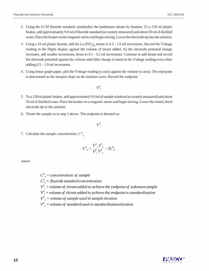
2. Using the 0.l M fluoride standard, standardize the lanthanum nitrate by titration. To a 150 ml plasticbeaker, add approximately 9.0 ml of fluoride standard (accurately measured) and about 50 ml of distilledwater. Place the beaker on the magnetic stirrer and begin stirring. Lower the electrode tip into the solution.
3. Using a 10 ml plastic burette, add the La (NO3)3 titrant in 0.5 - 1.0 ml increments. Record the Voltagereading in the Digits display against the volume of titrant added. As the electrode potential changeincreases, add smaller increments, down to 0.1 - 0.2 ml increments. Continue to add titrant and recordthe electrode potential against the volume until little change is noted in the Voltage reading even whenadding 0.5 - 1.0 ml increments.
4. Using linear graph paper, plot the Voltage reading (y-axis) against the volume (x-axis). The end-pointis determined as the steepest slope on the titration curve. Record the endpoint.
V0t
5. To a 150 ml plastic beaker, add approximately 9.0 ml of sample solution (accurately measured) and about50 ml of distilled water. Place the beaker on a magnetic stirrer and begin stirring. Lower the rinsed, driedelectrode tip in the solution.
6. Titrate the sample as in step 3 above. The endpoint is denoted as:
VXt
7. Calculate the sample concentration, C xs
CXS =
VXt V0
f
V0t VX
f
– 2C0S
where:
CXS = concentration of sample
C0S = fluoride standard concentration
VXt = volume of titrant added to achieve the endpoint of unknownsample
V0t = volume of titrant added to achieve the endpoint in standardization
VXf = volume of sample used in sample titration
V0f = volume of standard used in standardizationtitration
012–06619A Fluoride Ion Selective Electrode
11
A typical titration curve is shown in Figure 4.
Electrode Characteristics
Reproducibility
Electrode measurements reproducible to ±2% can be obtained if the electrode is calibrated every hour. Factors suchas temperature fluctuations, drift, noise, and variations in illumination limit reproducibility. Reproducibility isindependent of concentration within the electrode’s operating range.
Interferences
The hydroxide ion, OH-1, is an electrode interference. Anions which make the sample more basic, such as CO3-2
or PO4-3 would increase the OH-1 interference, but do not interfere with direct electrode operation. Other anions
commonly associated with fluoride, such as Cl-1, Br-1, I -1, SO4-2, HCO3
-l, NO3-1 and acetate, do not interfere with
correct electrode operation. Most cations do not interfere with the response of the fluoride electrode to fluoride ion.
Complexation
Hydrogen ion, as well as some other multivalent cations, aluminum, silicon, iron+3, will form complexes withfluoride. The total ionic strength of the solution, the pH of the solution, the total fluoride concentration, and theconcentration of the complexing agent all contribute to the degree of complexation. TISAB 1 and TISAB 2 complexabout 5 ppm aluminum or iron in a 1 ppm fluoride solution. TISAB 3 complexes higher levels of iron and aluminum.
5 10 20 25
+100
+50
0
-50
-100
15
ml of 0.1 M La(NO3)
3
electrodepotential(mV)
Figure 4Titration of 25 ml of 0.112 M F- with 0.100 M La (NO
3)
3
Fluoride Ion Selective Electrode 012–06619A
12
Temperature Influences
Samples and standards should be within ±l °C of each other, since electrode potentials are influenced by changesin temperature. Because of solubility equilibria on which the electrode depends, the absolute potential of thereference electrode changes slowly with temperature. The slope of the electrode, as indicated by the factor “S” inthe Nernst equation, also varies with temperature. Table 3 gives values for the ‘S” factor in the Nernst equation forthe fluoride ion.
TABLE 3: Temperature vs. Theoretical Values for the Electrode Slope
Temperature (ºC) “S”0 54.2010 56.1820 58.1625 59.1630 60.1540 62.1350 64.11
The temperature range for the PASCO scientific Fluoride Ion Selective Electrode is 0 °C - 80 °C, provided thattemperature equilibrium has occurred. Only intermittent use is recommended at temperatures from 80 °C - l00 °C.If the temperature varies substantially from room temperature, equilibrium times up to one hour are recommended.
Electrode Response
Plotting the electrode potential against the fluoride concentration on semi-logarithmic paper results in a straight linewith a slope of about 57 mV per decade. (Refer to Figure 1.)
The time needed to reach 99% of the stable electrode potential reading, the electrode response time, varies fromone minute or less in highly concentrated solutions to several minutes near the detection limit. See Figure 5.
A drifting potential reading or a decrease in electrode slope may mean that the electrode membrane needs polishing.
-160
-80
0
+80
1 2 3 4
10-3 M to 10-6 M NaF
10-3 M to 10-5 M NaF
10-3 M to 10-4 M NaF
10-3 M to 10-2 M NaF
Figure 5Typical electrode time response to step changes in NaF-
time (minutes)
electrodepotential(mV)
012–06619A Fluoride Ion Selective Electrode
13
Limits of DetectionFluoride concentration down to l.0Xl0-6 M (0.02 ppm) fluoride can be measured in neutral solutions. Since samplecontamination can be a factor in low level fluoride measurements, care must be taken in making determinationsbelow l.0Xl0-5 M. The upper limit of detection is a saturated fluoride solution.
pH EffectsHydrogen complexes a portion of fluoride in solution, forming the un-dissociated acid HF and the ion HF2
-1 in acidsolutions with a pH below 5. The proportion of free fluoride ion in acid solutions is shown in Figure 6.
When the level of hydroxide is greater than one-tenth the level of fluoride ion present, hydroxide ion interferes withelectrode response to fluoride. As an example, no hydroxide interference with fluoride measurements take placeat pH 7 when the hydroxide concentration is l.0Xl0-7 or less. As the pH increases, the hydroxide interferencebecomes appreciable. At pH 10, the hydroxide ion concentration is l.0x10-4 M and no error is found in measurementsof l.0Xl0-2 M fluoride. At the same hydroxide ion concentration and a fluoride concentration of l.0xl0-4 M, abouta 10% measurement error appears. At a fluoride concentration of l.0Xl0-5 M, considerable error exists in a pH 10solution. Figure 7 illustrates these errors.
1 2 4 50
20
40
60
80
3
HF
6
100
Figure 6Fraction of free F - as a function of solution pH, where the hydrogen is the only complexing agent
pH
% ofspecies
+50
+25
0
-25
7 8 9 11
+75
+100
10
10-3 M F-
10-4 M F-
10-5 M F-
Figure 7Electrode response in alkaline solution
solution pH
electrodepotential(mV)
Fluoride Ion Selective Electrode 012–06619A
14
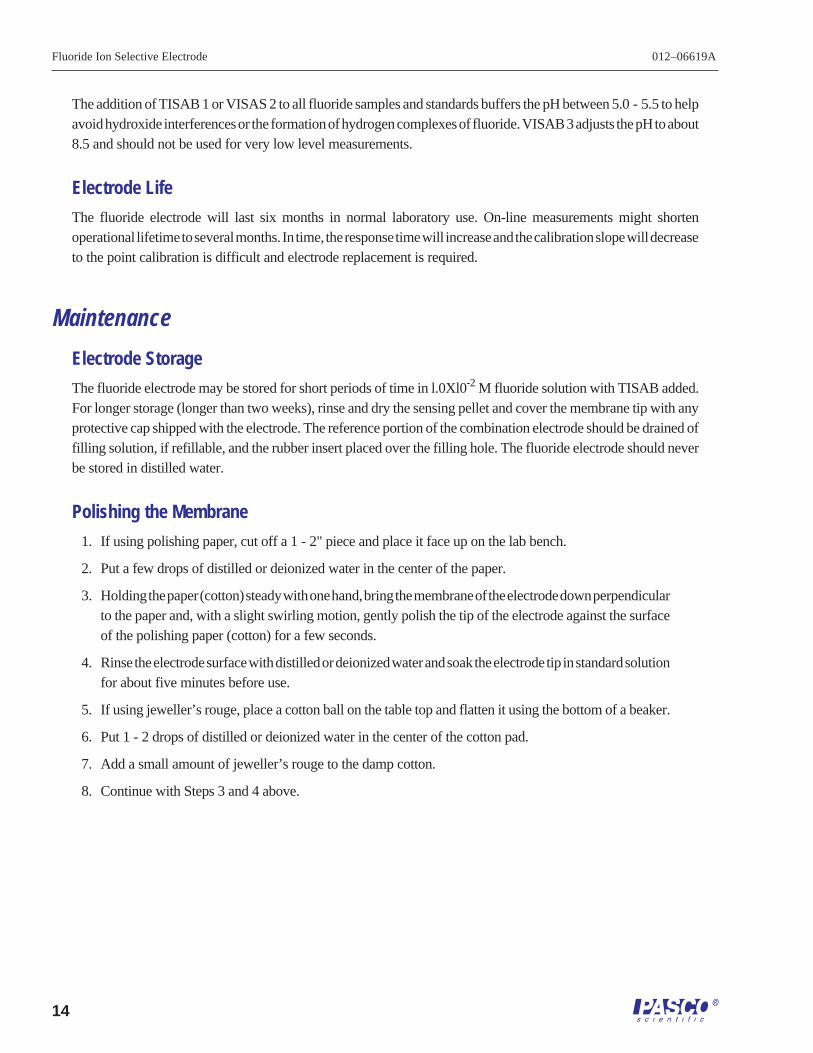
The addition of TISAB 1 or VISAS 2 to all fluoride samples and standards buffers the pH between 5.0 - 5.5 to helpavoid hydroxide interferences or the formation of hydrogen complexes of fluoride. VISAB 3 adjusts the pH to about8.5 and should not be used for very low level measurements.
Electrode Life
The fluoride electrode will last six months in normal laboratory use. On-line measurements might shortenoperational lifetime to several months. In time, the response time will increase and the calibration slope will decreaseto the point calibration is difficult and electrode replacement is required.
Maintenance
Electrode Storage
The fluoride electrode may be stored for short periods of time in l.0Xl0-2 M fluoride solution with TISAB added.For longer storage (longer than two weeks), rinse and dry the sensing pellet and cover the membrane tip with anyprotective cap shipped with the electrode. The reference portion of the combination electrode should be drained offilling solution, if refillable, and the rubber insert placed over the filling hole. The fluoride electrode should neverbe stored in distilled water.
Polishing the Membrane
1. If using polishing paper, cut off a 1 - 2" piece and place it face up on the lab bench.
2. Put a few drops of distilled or deionized water in the center of the paper.
3. Holding the paper (cotton) steady with one hand, bring the membrane of the electrode down perpendicularto the paper and, with a slight swirling motion, gently polish the tip of the electrode against the surfaceof the polishing paper (cotton) for a few seconds.
4. Rinse the electrode surface with distilled or deionized water and soak the electrode tip in standard solutionfor about five minutes before use.
5. If using jeweller’s rouge, place a cotton ball on the table top and flatten it using the bottom of a beaker.
6. Put 1 - 2 drops of distilled or deionized water in the center of the cotton pad.
7. Add a small amount of jeweller’s rouge to the damp cotton.
8. Continue with Steps 3 and 4 above.
012–06619A Fluoride Ion Selective Electrode
15
SpecificationsConcentration Range: saturated solutions to 1.0Xl0-6 M (0.02 ppm)
pH Range: 5 to 7 at 1.0Xl0-6 M F -1 (0.02 ppm F-1)5 to 11 at 1.0Xl0-1 M F -1 (1900 ppm F-1)
Troubleshooting GuideThe goal of troubleshooting is the isolation of a problem through checking each of the system components in turn:the meter, the plastic-ware, the electrodes, the standards & reagents, the sample, and the technique.
Plastic-ware
Clean plastic-ware is essential for good measurement. Be sure to wash the plastic-ware well with a mild detergentand rinse very well with distilled or deionized water.
Electrode
The electrode may be checked by using the procedure found in the sections entitled Electrode Slope Check.
1. Be sure to use distilled or deionized water when following the procedures given in Electrode SlopeCheck.
2. If the electrode fails to respond as expected, see the sections Measuring Hints and Electrode Response.Repeat the slope check.
3. If the electrodes still fail to respond as expected, substitute another Fluoride Ion Selective Electrode (ifavalable) that is known to be in good working order for the questionable electrode.
4. If the problem persists, the reagent may be of poor quality, interferences in the sample may be presentor the technique may be faulty. (See Standards & Reagents, and Technique sections below.)
Fluoride Ion Selective Electrode 012–06619A
16
5. If another electrode is not available for test purposes, or if the electrode in use is suspect, review theinstruction manual and be sure to:
- Clean and rinse the electrodes thoroughly.
- Prepare the electrodes properly.
- Use the proper filling solution.
- Adjust the pH and the ionic strength of the solution by the use of the proper TISAB.
- Measure correctly and accurately.
- Review Troubleshooting Hints.
Standards & Reagents
Whenever problems arise with the measuring procedure that has been used successfully in the past, be sure to checkthe standard and reagent solutions. If in doubt about the credibility of any of the solutions, prepare them again. Errorsmay result from contamination of the TISAB, incorrect dilution of standards, poor quality distilled/deionized water,or a simple mathematical miscalculation.
Sample
Look for possible interferences, complexing agents, or substances which could affect the response or physicallydamage the sensing electrode if the electrode works perfectly in the standard, but not in the sample.
Try to determine the composition of the samples prior to testing to eliminate a problem before it starts. (SeeMeasuring Hints, Sample Requirements, and Interferences.)
Technique
Be sure that the electrode’s limit of detection has not been exceeded. Be sure that the analysis method is clearlyunderstood and incompatible with the sample.
Refer to the instruction manual again. Reread General Preparation and Electrode Characteristics.
If trouble still persists, call PASCO scientific Technical Support.
012–06619A Fluoride Ion Selective Electrode
17
Troubleshooting Hints
Symptom Possible Causes Next Step
Out of Range Reading defective electrode check electrode operation
electrodes not plugged in unplug electrodes and reseat electrodesproperly
reference electrode not filled replenish reference filling solution
electrodes not in solution put electrodes in solution
air bubble on membrane remove bubble by re-dipping electrode
Noisy or Unstable electrode exposed to interferences soak electrode in fluoride standardReadings (readings with added TISABcontinuously or rapidlychanging) defective electrode replace electrode
TISAB not used use recommended TISAB
stirrer not grounded ground stirrer
air bubble on membrane remove bubble by re-dipping electrode
Drift (reading slowly samples and standards at different allow solutions to come to room temperaturechanging in one direction) temperatures before measurement
electrode exposed to complexing check section entitled Complexationagents
incorrect reference filling solution use recommended filling solution
Fluoride Ion Selective Electrode 012–06619A
18
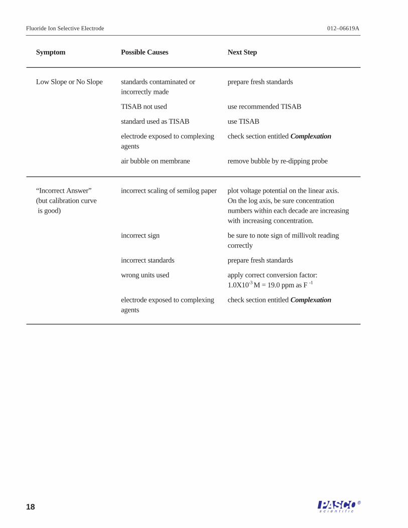
Symptom Possible Causes Next Step
Low Slope or No Slope standards contaminated or prepare fresh standardsincorrectly made
TISAB not used use recommended TISAB
standard used as TISAB use TISAB
electrode exposed to complexing check section entitled Complexationagents
air bubble on membrane remove bubble by re-dipping probe
“Incorrect Answer” incorrect scaling of semilog paper plot voltage potential on the linear axis.(but calibration curve On the log axis, be sure concentration is good) numbers within each decade are increasing
with increasing concentration.
incorrect sign be sure to note sign of millivolt readingcorrectly
incorrect standards prepare fresh standards
wrong units used apply correct conversion factor:1.0X10⁻³ M = 19.0 ppm as F-1
electrode exposed to complexing check section entitled Complexationagents
Technical Support
Feedback
If you have any comments about the product ormanual, please let us know. If you have anysuggestions on alternate experiments or find a problemin the manual, please tell us. PASCO appreciates anycustomer feedback. Your input helps us evaluate andimprove our product.
To Reach PASCO
For technical support, call us at 1-800-772-8700(toll-free within the U.S.) or (916) 786-3800.