FOCUS Program Overview B. PROGRAM OVERVIEW 1. SUMMARY Through the FOCUS Program, ARPA-E will fund the development of disruptive new technologies to optimally exploit the full solar spectrum and reduce the cost of solar energy when the sun is not shining. Figure 2 schematically illustrates the two technologies addressed by the FOCUS FOA. One category of awards is for new hybrid solar converter technologies to provide both heat, which can be stored at low-cost for later use, and electricity. A second category of awards is for new hybrid storage technologies that can leverage the simultaneous availability of both solar electricity and heat to dispatch solar electricity whenever needed. The devices and technologies that emerge from the FOCUS Program have the potential to go beyond photovoltaic, concentrating solar power and electricity storage paradigms, to dramatically increase the penetration of solar energy into the U.S. energy mix. Figure 2. Schematics of technology areas addressed by the FOCUS FOA. a) Hybrid solar converter (award Categories 1A and 1B). b) Hybrid storage system (award Category 2). The term “dispatchable” indicates availability as needed. 2. MOTIVATION High utilization of solar energy is an important component of future energy scenarios with reduced carbon-dioxide emissions. 1 Solar energy systems can also provide secure energy with predictable future costs, largely unaffected by geopolitics and global energy markets, because sunshine is widely available and free. Despite the impressive technology and deployment advances made by solar photovoltaics (PV), today’s high-cost electricity storage options will likely limit PV penetration to less than about 5% of U.S. primary energy before significant PV curtailments will be needed at times of high solar availability. 2, 3 Meanwhile, concentrating solar power (CSP), solar heating and solar hot water applications together contribute less than 0.1% of U.S. primary energy, and their deployment is growing only slowly. The primary goal of this FOA is to provide disruptive new solar conversion and storage technology options to enable much higher penetration of solar energy generation into the U.S. energy mix. Electricity generation from sunlight by photovoltaics, through direct conversion using a semiconductor absorber, has grown into a $100 billion per year global industry. This growth is fueled by the availability of increasingly efficient PV modules at rapidly falling prices. In sunny locations with moderate or high electricity costs, PV now provides electricity at prices at or below parity with grid electricity. This “grid parity” is becoming more geographically widespread, accelerating the deployment of PV in the U.S. and globally. Photovoltaics now generate about 0.1% of U.S. electricity, and PV generation is projected to reach 3% penetration in California by 2015. 4 The DOE’s SunShot Program supports research 1 O. Edenhofer, et al. (eds), Intergovernmental Panel on Climate Change, “Special Report on Renewable Energy Sources and Climate Change Mitigation.” (2011) Prepared by Working Group III of the Intergovernmental Panel on Climate Change (IPCC), Cambridge Universi ty Press, Cambridge, United Kingdom, 1075 pp. 2 PV limited to about 10% of electricity without curtailments. IPCC, “Special Report on Renewable Energy Sources and Climate Change Mitigation,” (2011) Ch. 8. 3 Electricity provides about 40% of U.S. primary energy, U.S. Energy Information Administration, Monthly Energy Review (April 2012), Tables 1.3,2.1- 2.5. 4 U.S. Energy Information Administration, Annual Energy Outlook (2013)
Transcript
FOCUS Program Overview
B. PROGRAM OVERVIEW
1. SUMMARY
Through the FOCUS Program, ARPA-E will fund the development of disruptive new technologies to optimally exploit the full solar spectrum and reduce the cost of solar energy when the sun is not shining. Figure 2 schematically illustrates the two technologies addressed by the FOCUS FOA. One category of awards is for new hybrid solar converter technologies to provide both heat, which can be stored at low-cost for later use, and electricity. A second category of awards is for new hybrid storage technologies that can leverage the simultaneous availability of both solar electricity and heat to dispatch solar electricity whenever needed. The devices and technologies that emerge from the FOCUS Program have the potential to go beyond photovoltaic, concentrating solar power and electricity storage paradigms, to dramatically increase the penetration of solar energy into the U.S. energy mix.
Figure 2. Schematics of technology areas addressed by the FOCUS FOA. a) Hybrid solar converter (award Categories 1A and 1B). b) Hybrid storage system (award Category 2). The term “dispatchable” indicates availability as needed.
2. MOTIVATION
High utilization of solar energy is an important component of future energy scenarios with reduced carbon-dioxide emissions.
1 Solar energy systems can also provide secure energy with predictable future costs, largely unaffected by
geopolitics and global energy markets, because sunshine is widely available and free. Despite the impressive technology and deployment advances made by solar photovoltaics (PV), today’s high-cost electricity storage options will likely limit PV penetration to less than about 5% of U.S. primary energy before significant PV curtailments will be needed at times of high solar availability.
2, 3 Meanwhile, concentrating solar power (CSP), solar heating and solar hot water applications
together contribute less than 0.1% of U.S. primary energy, and their deployment is growing only slowly. The primary goal of this FOA is to provide disruptive new solar conversion and storage technology options to enable much higher penetration of solar energy generation into the U.S. energy mix. Electricity generation from sunlight by photovoltaics, through direct conversion using a semiconductor absorber, has grown into a $100 billion per year global industry. This growth is fueled by the availability of increasingly efficient PV modules at rapidly falling prices. In sunny locations with moderate or high electricity costs, PV now provides electricity at prices at or below parity with grid electricity. This “grid parity” is becoming more geographically widespread, accelerating the deployment of PV in the U.S. and globally. Photovoltaics now generate about 0.1% of U.S. electricity, and PV generation is projected to reach 3% penetration in California by 2015.
4 The DOE’s SunShot Program supports research
1 O. Edenhofer, et al. (eds), Intergovernmental Panel on Climate Change, “Special Report on Renewable Energy Sources and Climate Change
Mitigation.” (2011) Prepared by Working Group III of the Intergovernmental Panel on Climate Change (IPCC), Cambridge University Press, Cambridge, United Kingdom, 1075 pp. 2 PV limited to about 10% of electricity without curtailments. IPCC, “Special Report on Renewable Energy Sources and Climate Change Mitigation,”
(2011) Ch. 8. 3 Electricity provides about 40% of U.S. primary energy, U.S. Energy Information Administration, Monthly Energy Review (April 2012), Tables 1.3,2.1-
2.5. 4 U.S. Energy Information Administration, Annual Energy Outlook (2013)
2 FOCUS Program Overview
and development (R&D) for continued cost reductions and improvements in PV sunlight-to-electricity conversion efficiencies. Despite this momentum, storage of PV electricity remains expensive. The high cost of grid electricity storage makes it best suited for high-value, short-term, frequency regulation; the lower value market for peak-shifted photovoltaic electricity is largely unprofitable, except where geography provides suitable reservoirs for lower-cost pumped-storage hydroelectricity.
5
Penetration of PV will ultimately be limited unless breakthrough technologies enable hours of electricity generated by PV to be cost-effectively stored. Models of the solar-resource-rich California electricity grid show that PV curtailments will begin at penetrations as low as 12%, while about one-third of PV electricity would be curtailed at penetrations of ~28%.
6
The marginal economic value of installing PV is predicted to fall by half when PV meets more than 20% of the California utility load.
7 The current state of the German electrical grid provides a glimpse into the likely future of grid-parity PV in the
United States. In Germany, about 5% of annual electrical energy production is now from solar resources, and solar energy frequently contributes more than 20% of the required grid power on a summer day.
8 This level of solar penetration is
enabled only through a combination of demand-side management, trading of surplus power at low cost to neighboring jurisdictions, and dispatch of expensive natural gas peaking or load-following plants. Higher penetration of solar energy would require either slowdowns of generation from baseload plants, a function that they are not designed to perform efficiently, or dumping of surplus solar electricity. A recent analysis finds that a new German program offering up to 660 EUR/kW subsidy for storage tied to PV will not lower battery payback periods enough to induce new investment.
9
Germany’s solar incentives now require PV systems to have a curtailment capability, to allow shut-off during periods of grid instability.
10
Concentrating solar power systems have long been seen as a potentially attractive alternative to PV from the standpoint of grid integration. CSP generates solar electricity by focusing the direct component of sunlight and collecting the heat to power an electricity-generating turbine. Today, the levelized cost of electricity (LCOE) from CSP is roughly twice that of PV electricity. However, CSP systems have a low incremental cost of heat storage that enables dispatch of electricity when it is most needed. The heat collected is typically stored as sensible heat in molten salts, where the stored thermal energy can be extracted later with almost no loss. Today’s cost of this thermal energy storage (TES) is approximately $30/kWhth,
11 equivalent to ~$75/kWhe
12 and already lower than the aggressive $100/kWhe research goals for short-term
electrical storage.5 As PV penetration into electricity generation grows, the periods of greatest demand (and highest value) for electricity on the grid will increasingly move outside of PV operating hours.
13 As a result, some U.S. jurisdictions have already
bypassed less expensive PV projects in favor of CSP equipped with thermal energy storage, such as Arizona Public Service Company’s procurement of 280 MW of CSP capacity.
13 Similarly, in early 2013 the California Public Utilities
Commission authorized a utility power purchase agreement from a CSP plant with TES. Although the kWhe cost was higher than competing PV systems, the Commission deemed the project more valuable because of its operational flexibility.
14 Despite the advantages of low-cost thermal energy storage, however, only about 2 GW of CSP is installed
worldwide, compared to about 100 GW of PV. Today’s PV and CSP solutions alone cannot provide the combination of low LCOE and dispatchable output that will be required to enable large-scale solar energy utilization outside daytime hours. Figure 3 schematically illustrates today’s low cost of PV electricity, the lack of PV dispatchability, the higher cost of dispatchable CSP electricity, and the high cost of adding electrical storage to increase the dispatchability of PV electricity. The FOCUS Program aims to develop solar energy conversion and storage innovations to economically address energy needs at times when PV electricity is unavailable (“FOCUS” in Figure 3). To succeed, multidisciplinary efforts must develop innovative technologies based on
5 ARPA-E GRIDS Funding Opportunity Annoucement,
https://arpa-e-foa.energy.gov/FileContent.aspx?FileID=98c6222e-471c-4216-a377-024dbdb45549 6 Denholm, P.; Mehos, M. “Quantifying the Value of CSP with Thermal Energy Storage” Phoenix: SunShot CSP Program Review. (2013) Slide 27
7 Mills, A.; Wiser, R. “Changes in the Economic Value of Variable Generation at High Penetration Levels: A Pilot Case Study of California.”LBNL-5445E
(2012). 8 Burger, B. “Electricity production from solar and wind in Germany in 2012”. Freiburg: Fraunhofer Institute for Solar Energy Systems ISE. (2013)
9 Bloomberg New Energy Finance. “Will Germany’s energy storage subsidy spur investment?”. London. (2013) p. 1.
10 Fulton, M. and Capalino, R., “The German Feed-in Tariff: Recent Policy Changes.” New York: Deutsche Bank (2012) p. 21
11 Kolb, G.; Ho, C.; Mancini, T.; Gary, J. “Power Tower Technology Roadmap and Cost Reduction Plan.’ SAND2011-2419. (2011)
12 ARPA-E Calculation: Assumes an average CSP steam Rankine turbine efficiency of 40%.
13 Alpert, B. “Integrating CSP w/ TES into a Utility System” Phoenix: SunShot CSP Program Review. (2013)
14 California Public Utilities Commission, Resolution E-4545. Pacific Gas and Electric Company requests approval of an amended and restated power
purchase agreement with Rice Solar Energy, LLC which is a subsidiary of SolarReserve, LLC. San Francisco. (2013) p. 4
3 FOCUS Program Overview
advanced ideas from CSP, PV, storage and other technologies. However, there is scant history of joint work between separate PV and CSP communities that are mainly comprised of scientists and engineers with little overlap in their training and fields of interest. A secondary goal of the FOCUS Program is to promote collaborations among diverse communities of researchers to develop systems that generate inexpensive dispatchable solar energy.
Figure 3. Schematic comparing the cost and dispatchability of PV to CSP with thermal storage. The “PV+Storage” box includes the high cost of electrical storage for PV. The FOCUS Program target zone for electricity generation is indicated.
Finally, ARPA-E has noted a significant barrier that slows the development of current solar power systems with storage capability: new thermal solar plants have extremely high capital costs, often in the billion dollar range, driven by economies of scale in turbines and field construction, as well as the fixed costs of planning and permitting CSP systems. Only about 100 CSP plants are installed worldwide,
15 sharply limiting technology trials and learning cycles. While
innovation in utility-scale solar generation remains its central goal, the FOCUS Program also provides opportunities to develop smaller hybrid solar converters and storage systems that can be deployed in lucrative entry markets. Such entry markets enable increased R&D, stimulate mass manufacturing of system components and allow for rapid learning by
engineering design iteration all keys to rapid technology improvement and energy-significant deployment. The landscapes of future energy generation, distribution, pricing and consumption are complex, but key themes emerge from ARPA-E technology analysis and motivate the FOCUS Program: 1) PV technology is rapidly advancing and has enormous growth potential, but in less than a decade the lack of PV electricity dispatchability will slow solar deployment growth; 2) there is a high risk that conventional electrical storage will be unable to shift significant amounts of PV electricity to evening and night hours; 3) although CSP can integrate inexpensive thermal energy storage, the cost of CSP solar energy capture is high; and 4) the scale of capital investment associated with CSP is a significant barrier to iteration of designs and rapid innovation.
A. PROGRAM OBJECTIVES The overarching objective of the FOCUS Program is to create disruptive new solar energy conversion and storage technology options that enable far higher penetration of solar energy into the U.S. energy system than could be expected using only today’s PV, CSP and electrical storage options. Technical pathways to this goal include: 1) concentrating hybrid solar energy converters that optimize the utilization of the entire solar spectrum by inexpensively converting sunlight to both heat and electricity; and 2) inexpensive hybrid energy storage devices that require both electricity and heat as inputs, with electricity as the output. At technology maturity, energy systems incorporating these advanced converters and storage devices will be cost-competitive with other solutions: for example, electricity projects at utility scale will make dispatchable solar electricity competitive with conventional generation. A subsidiary objective of the FOCUS Program is to form a diverse research community (including, e.g., CSP mechanical engineers, PV semiconductor materials and device scientists, optics/photonics experts, chemists, low-cost manufacturing experts and system integrators) who will innovate together. Successful FOCUS projects will reduce energy-related emissions, decrease U.S. dependence on foreign energy sources, and provide U.S. leadership in advanced solar energy technology.
B. TECHNICAL BACKGROUND
1. Introduction
To stimulate interdisciplinary collaboration among Applicants to the FOCUS FOA, this Section presents technical background to the goals of the FOCUS Program, including calculated efficiencies of some simple technical approaches. The technical examples are meant only to illustrate principles; they are not meant to prescribe or limit the technical approaches that might receive an award through the FOCUS Program. ARPA-E is most interested in making awards to Applicants that effectively address a Technical Category of Interest described in Section I.E of the FOA and leads to the development of technology that can meet or exceed the associated Technical Performance Targets specified in Section I.F of the FOA. ARPA-E will make awards only to disruptive solutions that go beyond the state-of-the-art.
2. Solar Resource
The amount of solar energy striking the earth in one hour is roughly equal to the amount of primary energy humans use in a year. However, at ~ 1 kW/m
2 power density at the earth’s surface, sunlight must be intercepted and then converted to
usable energy at high efficiency and extremely low cost per unit collection area. A second challenge lies in the broad spectrum of incident sunlight, which spans nearly an order of magnitude in wavelength, from about 0.25 to 2.5 µm (0.5 to 5 eV photons). Efficient solar energy systems will require optimal use of the entire solar spectrum. A third challenge is presented by the angular distribution of the sunlight reaching Earth’s surface: even the direct component of sunlight has a finite angular width of about 5 degrees,
16 and a significant fraction of sunlight is diffuse in every geographic area, reaching
Earth’s surface only after scattering in the atmosphere.
3. Exergy and Hybrid Solar Converters
Exergy (X) is the maximum usable work that can be extracted from a system at elevated temperature (T) as it comes to equilibrium with a cooler heat reservoir. CSP systems focus and collect heat energy, Q, from a broad spectrum of incident solar photons at a sunlight-to-heat energy efficiency of 50 to 80%. Ideally, this solar heat could be converted to electricity by a heat engine at the Carnot efficiency limit of (1 – Tc/Th) that depends on the ratio between the hot (Th) and cold (Tc) Kelvin temperatures driving the heat engine. Thus, the exergy content, Xth, of solar heat collected at Th is Q(1-Tc/Th). To calculate exergy, the FOCUS Program assumes Tc = 310K, as in typical hybrid-cooled heat engines. One promising path to increasing the efficiency in solar heat-to-electricity systems is to increase the maximum temperature reached by the heat-collecting fluid. The solar spectrum reaching the earth is characteristic of a blackbody with an effective temperature of ~5500°C. Simply collecting solar heat in a thermal fluid at Th =600°C immediately wastes more than 35% of the incident solar exergy. The DOE SunShot Program and ARPA-E support a range of technologies
16
ASTM E816 - 05, Standard Test Method for Calibration of Pyrheliometers by Comparison to Reference Pyrheliometers (2010)
5 FOCUS Program Overview
that could raise Th in CSP above 600°C, to as high as 1200°C. Increasing Th would raise the exergy content of the captured solar heat and improve CSP heat engine efficiencies. However, developing systems with Th above 600°C presents high technical risk. Key technical challenges to overcome include: large heliostat mirror fields that have inherently low optical efficiency and must therefore be extremely low cost; stable thermal fluids; low-cost robust materials for piping, pumping and storing these high T fluids; advanced high T engines (e.g., based on supercritical CO2); and high efficiency thermal receivers that overcome the problem of radiation losses at high T. Alternatively, high sunlight-to-exergy efficiency could be obtained with a hybrid solar “topping” converter, while still providing a high fraction of inexpensively stored solar heat. A topping collection device interposed between the sun and the thermal fluid would enable the solar converter to capture more of the solar exergy. For example, photovoltaic cells can collect photoexcited carriers before they relax to thermal equilibrium; the carriers remain at an extremely high “effective temperature” when they are collected as electricity. With effective heat transfer to a thermal fluid, conversion losses in the topping device could be collected as heat for use in a more conventional thermal “bottoming” cycle. Thus, a hybrid solar converter delivers its energy in two forms: as topping electricity produced when the sun is shining and as heat that can be efficiently stored. The simplest hybrid solar converter to analyze has a topping device illuminated by concentrated sunlight, which provides its waste heat to an underlying thermal fluid (inset to Figure 4b). The electricity produced directly from sunlight in the topping device is fully available as exergy.
17 Thus, the exergy efficiency ηX of a hybrid solar converter with a topping
device providing electric power Ptop and collecting thermal energy at a rate given by dQ/dt is
𝜂X =[𝑃top+
𝑑𝑄
𝑑𝑡 (1−
𝑇c𝑇h
⁄ )]
𝑃sun ,
Eqn. (1)
where Psun is the solar power incident on the converter and the topping device efficiency is top =Ptop/Psun. Assuming that all incident solar energy not converted to electricity is collected as heat, dQ/dt = (1- top) Psun and the maximum exergy efficiency
18 of this hybrid solar converter is
𝜂X = 𝜂top + (1 − 𝜂top) (1 −𝑇c
𝑇h⁄ ) . Eqn. (2)
This exergy efficiency expresses the fraction of the solar energy collected that can be used to do work without violating the Second Law of Thermodynamics, given top. However, practical heat engines typically operate at a maximum efficiency of roughly 2/3 the Carnot limit above about 300°C (e.g., ~36% and 42% for engines using Th = 400°C and 600°C heat, respectively).
19 Therefore, the practical sunlight-to-electricity energy efficiency of a hybrid solar converter is
𝜂E = 𝜂top + 2
3(1 − 𝜂top) (1 −
𝑇c𝑇h
⁄ ) . Eqn. (3)
17
There is typically a 2- 4 % loss if the power is converted from DC output to grid AC electricity 18
Exergy efficiency is ARPA-E’s preferred figure of merit for hybrid solar converters. A practical heat engine could convert only ~2/3 of the exergy in heat to electricity, so Eqn (2) effectively increases the value of the electricity from heat by a factor of ~3/2. While it is impossible to foresee the future time-of-day pricing structure of electricity, a premium factor of at least ~1.5 for dispatchability is likely once local PV penetration is substantial and the peaks of net demand for additional solar electricity (subtracting PV electricity from actual demand) shift to the evening and morning hours. 19
Sunshot Vision Study (2012), p.115, http://www1.eere.energy.gov/solar/sunshot/vision_study.html
4. Example: PV Topping Devices and System Efficiency
High temperature photovoltaic, thermoelectric, and photothermionic
20,21 devices are some candidates for use as the high
T topping devices in concentrating hybrid solar converters. In this sub-section, the potential of single-junction PV as a topping device is analyzed, because PV cells are the most industrially-advanced of these candidate devices. Today, concentrating photovoltaic systems focus direct sunlight onto efficient solar cells to generate electricity. The CPV solar cells are normally operated well below 80°C to maintain high efficiency. To withstand high operating temperatures, re-imagined topping PV cells would need to incorporate robust dopant profiles and contacts, employ features to minimize dark current losses and avoid low-bandgap absorbers. PV cells could be remarkably efficient at elevated T if the bandgap is appropriately chosen and the cell is under optical concentration. Recently, device physics models were employed to estimate the dependence of single-junction PV cell recombination-limited efficiency over their operating T (from 100 to 800°C) and their operating bandgap, at optical concentrations between 100X and 2000X.
22 , 23 The calculations are consistent with measurements taken across a
narrower T range under 1-sun AM0 illumination.24
Figure 4 shows quadratic curve fits to 100X concentration efficiencies in the Shockley-Queisser (S-Q) limit
25 and for a “moderate”-recombination cell that has roughly 2%-absolute lower 1-sun
efficiency than today’s world record single-junction GaAs solar cell.26
Both the S-Q and moderate-recombination cells are dominated by radiative recombination. Note that the PV curves in Figure 4 are not representative of a single solar cell: they show the optimum modeled efficiency at each T with operating bandgap as a free parameter. For example, the moderate-recombination cell at 100°C has an operating bandgap of about 1.38 eV and the 400°C cell on the same curve has an operating bandgap of about 1.63 eV.
27
20
Schwede, J., et al. “Photon-enhanced thermionic emission for solar concentrator systems” Nature Materials (2010) 9, p. 762. 21
Tianyin, S.; Koeck, F.; Zhu, C.; Nemanich, R. “Combined visible light photo-emission and low temperature thermionic emission from nitrogen doped diamond films.” Applied Physics Letters (2011), 99, p. 202101. 22
Gray, J., ARPA-E Workshop: “Solar Beyond Grid Parity: Spectrum-Efficient Solar Energy for Dispatchable Electricity or Fuels,” (2013), http://www.arpa-e.energy.gov/sites/default/files/documents/files/SolarBeyondGridParity_Gray.pdf 23
Wilcox, J; Gray, J. , unpublished (2013) 24
Landis, G. A., et al. “High Temperature Solar Cell Development,” NASA John Glenn Research Center, Technical Report (2005), 2005-213431, p. 241. 25
Shockley, W.; Queisser, H. "Detailed Balance Limit of Efficiency of p-n Junction Solar Cells." Journal of Applied Physics (1961) 32, p. 510. 26
Green, M. A., Emery, K., Hishikawa, Y., Warta, W. and Dunlop, E. D. “Solar cell efficiency tables (version 39).” Progress in Photovoltaics: Research and Applications (2012), 20, p. 12. 27
This T range and variation in bandgap could be achieved in the III-V system or with other semiconductors. If epitaxial materials were used, lift-off cells would likley be needed. As with all concentrator PV cells, the allowed cell cost would increase with concentration ratio.
a)
7 FOCUS Program Overview
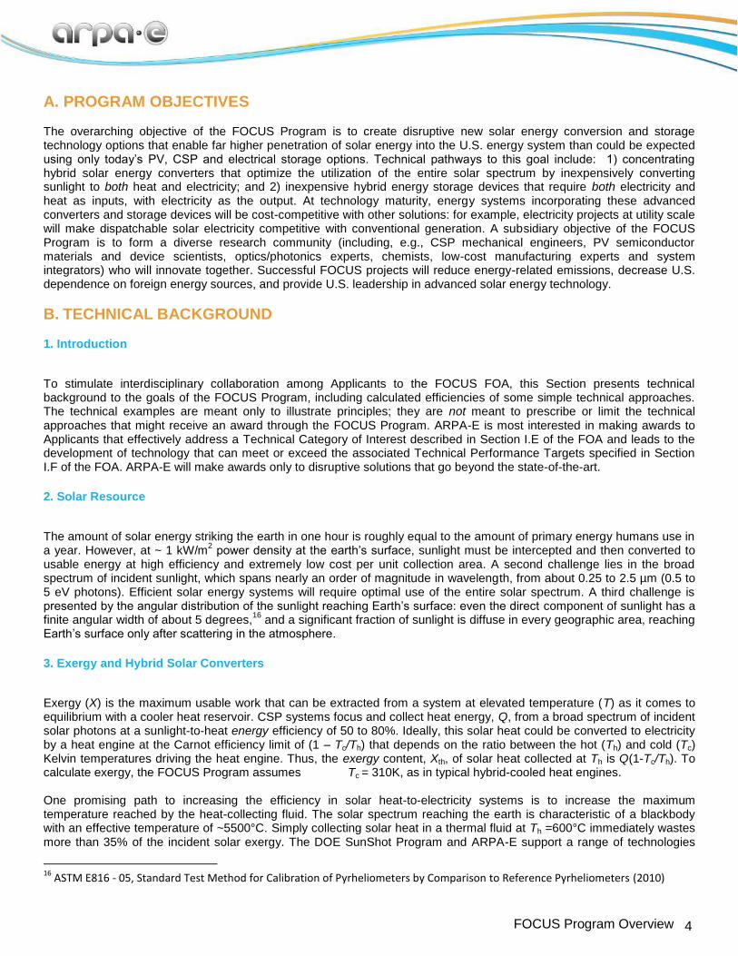
Figure 4. Calculated hybrid solar converter efficiencies versus T, using a PV topping device under 100X concentration and assuming 100% optical efficiency. Single-junction PV cells at the Shockley-Queisser limit (red) and with moderate recombination assumptions (black). a) Exergy efficiency at the Carnot limit. b) Electrical energy production efficiency with a practical heat engine at Th. The inset shows the simple hybrid solar converter modeled, with PV waste heat collected in a thermal fluid.
Figure 4 also shows the results of efficiency calculations using Eqns. (2) and (3) for the simple PV-topped hybrid solar converter system shown in the inset to Figure 4b, under 100X concentration. Perfect optical efficiency is assumed, including ideal PV anti-reflection. The only solar heat flowing into the thermal-fluid loop is waste heat from this PV, which must operate at the highest temperature in the system. Figure 4a shows the sunlight-to-exergy efficiency calculated from Eqn. (2) as a function of T for bandgap-optimized PV cells. The exergy efficiency varies from about 50% at 150°C to above 70% at 600°C with the S-Q limited PV cell, and is roughly 5%-absolute lower with the moderate-recombination PV topping cell. Figure 4b shows the Eqn. (3) sunlight-to-electrical energy efficiency for the same PV-based hybrid solar converter, now assuming practical heat engines. The energy efficiency limit calculated from Eqn. (2), for moderate-recombination PV, varies from about 40% at 150°C to nearly 50% at 600°C. It is worth noting that the converter reaches the same 46% energy efficiency at 400°C as could be reached by a purely thermal CSP system at 700°C. Hybrid solar converters reach high efficiency by utilizing the solar spectrum more fully than either CSP or PV systems alone.
28 PV cells are extremely efficient in converting photons with energies just above their bandgap into electricity. For
example, single-junction GaAs cells illuminated with laser monochromatic light have exceeded 50% efficiency29
and could be more than 60% efficient.
30 ,31 However, there is no absorption of photons with energy below the semiconductor
bandgap, and thermalization losses to the band edge reduce the efficiency in the blue and ultraviolet.32
Although increasing the operating T lowers the topping PV efficiency, the broad spectrum thermal collection compensates. By converting captured solar heat to electricity, 20-40% of PV losses at every wavelength are recovered. It is possible to envision many improvements that would raise the converter exergy output above that of the simple hybrid
28
Branz, H.M., ARPA-E Workshop: “Solar Beyond Grid Parity: Spectrum-Efficient Solar Energy for Dispatchable Electricity or Fuels,” (2013), http://www.arpa-e.energy.gov/sites/default/files/documents/files/SolarBeyondGridParity_Branz.pdf 29
Olsen, L.; Huber, D.; Dunhum, G.; Addis, F.; Anheier, N. “High efficiency monochromatic GaAs solar cells.” In: Proceedings of 22nd
IEEE Photovoltaic Specialist Conference. (1991) p. 419. 30
Green, M. “Limiting photovoltaic monochromatic light conversion efficiency.” Progress in Photovoltaics: Research and Applications (2001), 9, p. 257. 31
Henley, M.; Fikes, J.; Howell, J.; Mankins, J. “Space solar power technology demonstration for lunar polar applications: laser-photovoltaic wireless power transmission” (2002) Presentation to the World Space Congress, Houston, TX, http://ntrs.nasa.gov/archive/nasa/casi.ntrs.nasa.gov/20020091885_2002153397.pdf 32
Conversion of a wider spectral range of photons in multijunction cells has enabled 44% efficient triple junction cells under concentration. However, voltage loss mechanisms are nearly bandgap-independent [King, R.R., et al, “Bandgap engineering in high-efficiency multijunction concentrator cells.” Intl. Conf. on Solar Concentrators for the Generation of Electricity or Hydrogen. (2005), Scottsdale, AZ] and limit the ability of lowgap cells to efficiently use solar photons below 1 eV.
solar converter analyzed in Figure 4. Increasing the concentration ratio to 1000X would increase the 1-junction PV cell efficiency by about 2.5%-absolute,
23 and significant increases in topping efficiency could also be achieved by using
multijunction cells. With different converter design, PV cells could be placed in the highest T zones but also in illuminated zones where the thermal collection fluid is at a lower T and the PV efficiency would be higher. Spectral splitting approaches
33,34 can divert wavelengths converted poorly by PV to a secondary thermal receiver operating at a higher T
than the PV. In this case, the thermal fluid could reach temperatures higher than the topping PV. Spectral splitting could be implemented by use of PV that reflects photons it does not process efficiently, as in concentrating PV cavity converters,
35 or by spectrum splitting photonics.
5. HYBRID STORAGE OF HEAT AND ELECTRICITY FOR DISPATCHABLE ELECTRICITY
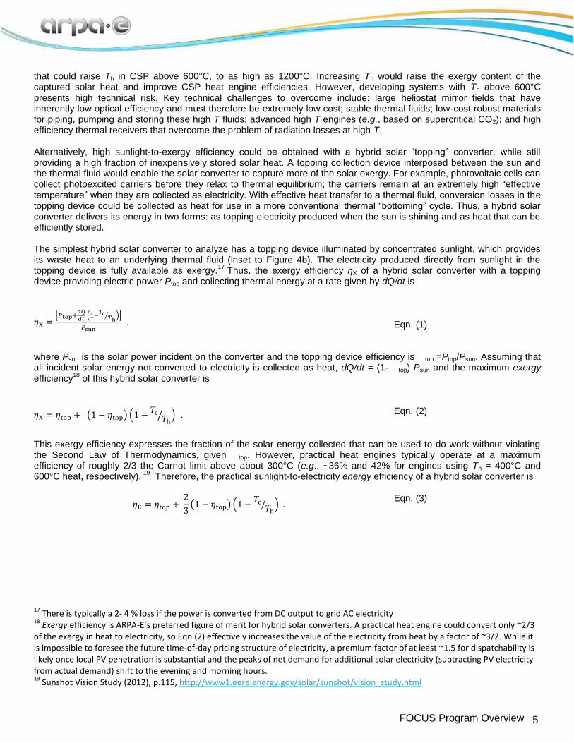
As described above, hybrid solar converters can be used in systems that produce some dispatchable electricity by storing solar heat. Better storage options for the topping electricity would enable dispatch of all the collected solar energy when needed. The simultaneous availability of the solar heat could help store the topping electricity by use of a hybrid storage system, shown schematically in Figure 2b. This system can be viewed as heat-enabled electricity storage and therefore presents different technical opportunities and challenges than the electricity-to-electricity paradigm exemplified by batteries, pumped hydroelectric and flywheel storage. Hybrid storage systems could also be used to enable high penetration of conventional PV into electricity generation. In conjunction with conventional thermal CSP systems or natural gas heat, hybrid storage systems could accept and store grid electricity during sunny hours and dispatch this electricity at any time of day. High-value hybrid storage systems must be more efficient than a side-by-side combination of today’s optimal heat-storage/generation and electrical-storage systems. Quantitatively, for a given ratio of heat to electrical exergy input, the hybrid storage system should return more electrical energy than could be output by a) storing the heat in a 65%-exergy-efficient TES/turbine system
36 and b) independently storing the electricity in an electrical storage system with a round-trip
efficiency of 75%. For a given ratio of exergy from electricity to total input exergy, Xelec/Xin, the desired exergetic efficiency is therefore greater than the weighted average between thermal and electrical storage systems (above the dotted line in Figure 5).
33
Kirkpatrick, D.; Eisenstadt, E.; Haspert, A. “DARPA’s Push for Photovoltaics,” Conference Record of the 2006 IEEE 4th World Conference on Photovoltaic Energy Conversion (2006), 2, p. 2556. 34
Groβ, B.; Peharz, G.; Siefer, G.; Peters, M.; Goldschmidt, J.; Steiner, M.; Guter, W.; Klinger, V.; George, B.; Dimroth, F. “Highly efficient light splitting photovoltaic receiver.” Proceedings of the 24
th European Photovoltaic Solar Energy Conference (2009), p. 130.
35 Ortabais, U. U.S. Patent No. 6690049 (2004)
36 Assumes a steam Rankine turbine operating at about 2/3 of its Carnot limit (vs. 310K) and a TES round-trip exergy efficiency of
97%.
9 FOCUS Program Overview
Figure 5. Round-trip exergy efficiency for heat and electricity hybrid storage, competitive with a combination of conventional pure heat and pure electricity storage. The dotted line shows the target of equivalent performance to a weighted average of TES with a steam Rankine and an electrochemical battery. An industrial compressed-air storage plant (CAES)
37 is plotted as an example of a system using electricity and
heat inputs to produce dispatchable electricity.
Thermomechanical systems that store electricity by compressing air, but add heat to raise the round-trip efficiency, provide a working example of hybrid storage today.
37 However, the present state-of-the art has not reached the required
round-trip exergy efficiency. The black square in Figure 5 shows the exergy efficiency of approximately 50% reached by a commercial system for an exergy input that is about 40% electricity. The system uses the electricity to compress air and, upon discharge, burns natural gas to add heat before expanding the air to drive a turbine. There are also technical opportunities using electrochemical reactions to produce storable energetic molecules, while also incorporating significant heat inputs. These energetic molecules could be used to generate dispatchable electricity. Many fuel-producing reactions have ∆Srxn> 0, which allows for the input of heat (T∆Srxn) in addition to electricity (∆Grxn). For example, a high-temperature electrolysis reaction operating with low overpotential could incorporate external heat into the reaction.
38,39 In this case, the conventional heat engine could be replaced by a fuel cell that might also function, reversibly,
as an electrolysis unit. Alternatively, hybrid chemical cycles, which employ a sequence of electrochemical and thermally-driven reactions to perform an overall reaction, have been developed.
40 Research on these hybrid chemical cycles has
focused almost exclusively on producing hydrogen transportation fuel, but the approach could be extended to other chemical systems to develop closed, chemically reversible cycles.
E. TECHNICAL CATEGORIES OF INTEREST
1. OVERVIEW
Applications to the FOCUS FOA must demonstrate convincingly that they will provide disruptive technology advancement in one or more of the Technical Categories of Interest described in this Section. Section I.F of the FOA contains the specific technical and cost targets that the proposed technologies must meet. Exceptional systems that combine the
37
EPRI Report TR-101751-V2, “History of First U.S. Compressed-Air Energy Storage (CAES) Plant (110 MW 26h): Volume 2: Construction”, S-3 (1994),
Hauch, A.; Ebbesen, S.; Jensen, S.; Mogensen, M. “Highly efficient high temperature electrolysis.” Journal of Materials Chemistry (2008), 18, p. 2331 39
O'Brien, J. “Thermodynamics and Transport Phenomena in High Temperature Steam Electrolysis Cells.” Journal of Heat Transfer (2012), 134, p.
031017. 40 Perret, R. “Solar Thermochemical Hydrogen Production Research (STCH): Thermochemical Cycle Selection and Investment Priority”, SAND2011-3622 (2011)
10 FOCUS Program Overview
functions and targets of both Categories 1A and 2 to meet the overall performance and cost goals of the FOA will also be considered for award. Section I.G of the FOA lists specific technologies that will not be considered for awards. Technical Category of Interest 1 is the development of critical technologies needed for high sunlight-to-exergy efficiency hybrid solar converters (see Figure 2a) that generate both heat and electricity. Category 1A applicants must describe the development of advanced hybrid solar converter technologies and prototypes. Applicant must also describe how the hybrid converter will be deployable, at technology maturity, as part of a complete solar system that addresses an energy-significant application space at prices competitive with today’s lowest energy costs. Category 1B applicants must describe the development of novel topping devices that can efficiently convert solar energy directly to electricity at operating temperatures above 400°C. These high-temperature topping devices will enable a second generation of hybrid solar converters. The FOCUS Program does not require integration of Category 1B topping devices into a complete hybrid solar converter, though Applicants should convincingly describe how the device could be integrated into a converter. Technical Category of Interest 2 is development of hybrid storage systems for heat and electricity (see Figure 2b) and the critical enabling technologies. These hybrid storage systems must generate electricity at higher round-trip exergy efficiency than is possible today using side-by-side combinations of purely electrical and purely thermal energy storage systems. The cost of a mature hybrid storage system must be low enough to permit topping electricity or PV electricity from the grid to be economically stored for later dispatch.
2. Details on Each Technical Category of Interest
2.1a. Category of Interest 1A: Applicants to Category 1A should demonstrate critical technology improvements to enable hybrid solar converters in which the highest temperature of the thermal energy collection is between 150°C and 600°C. This range provides a disruptive change to the state-of-the-art, yet avoids the complications and expense of materials for Th > 600°C. Utility-scale electricity generation is of particular interest to ARPA-E. Applicants should propose designs for durable hybrid solar converters that integrate optics, topping devices and thermal receivers, with an optimized balance between heat and topping electricity production, considering both the impacts on system costs and the proposed system application. ARPA-E is interested in proposals that incorporate one or more of the following technological advances to maximize hybrid solar converter exergy efficiency:
Hybrid solar converters in which a PV topping device is used at an intermediate temperature of a thermal
energy collection loop that has a peak Th incompatible with the efficient use of PV. Integrated spectrum-splitting approaches that place a spectrum-sensitive topping device on a secondary
reflector that is in contact with the thermal collection loop. The secondary reflector would divert certain wavelength photons (e.g., IR or UV for PV topping) to a higher T part of the thermal collection system.
I. Spectrally-selective thermal fluids flowing in front of the topping device to selectively absorb photons otherwise poorly
utilized in the topping device, including fluids working through nanoparticle absorption.
II. Hybrid solar converters that use a topping device other than PV cells, either alone or in conjunction with PV at lower T, to raise the system efficiency.
III. High-efficiency single-crystal PV cells that are lifted-off reusable substrates for use as topping devices at high T.
Such PV cells must be designed and tested for 25-year reliability under high T cycling or else be extremely inexpensive and incorporated in a converter that allows them to be economically replaced before they degrade.
IV. Efficient heat extraction from topping devices into the thermal collection medium with minimal loss of exergy.
V. Topping devices that are highly efficient within a particular spectral band and are integrated with a hybrid solar converter optical design to selectively direct those wavelengths to the topping devices.
11 FOCUS Program Overview
VI. Optics that economically collect and convert diffuse sunlight to electricity while also concentrating direct sunlight to a
hybrid topping converter.
Applicants to Category 1A may benefit from formation of interdisciplinary teams with expertise in more than one of the following areas: non-imaging optics, advanced optics and photonics, mechanical engineering, heat transfer, topping device design and fabrication, low-cost manufacturing, systems integration, reliability and solar system deployment. Applicants to Category 1A must describe how their proposed hybrid solar converters can be deployed in systems that would scale to provide energy at lower cost than competing technologies. In addition, they must designate a System Subcategory (see below) and provide cost data about the converter and the system in which the converter could be deployed. Section IV.D.1 of the FOA describes the different information that is required to be included in the Technical Volume for each System Subcategory. This system application should be described in sufficient detail for evaluation by reviewers and developed further during the award performance period System Subcategories. System applications of the hybrid solar converters in Category 1A must address one of the following System Subcategories:
A. System Subcategory UE: Systems that generate only utility-scale electricity (UE), as both variable topping electricity and collected heat used to generate electricity. Full Applications are required to include data about the complete system costs, as detailed in the Technical Volume guidelines (Section IV.D.1).
B. System Subcategory SE: Small- or intermediate-scale (SE) systems that generate only distributed electricity,
from hybrid solar converter units that are less than 1000 m2 in area. Individual units must support promising
systems applications. For rapid learning, the applicant must identify a promising market with potential for scale-up. Full Applications are required to include data about the complete system costs, as detailed in the Technical Volume guidelines (Section IV.D.1).
C. System Subcategory H: Small-or-intermediate scale systems that directly use the collected heat from hybrid
solar converter units which are less than 1000 m2 in area. For example, a system could use direct solar
electricity and heat (without converting solar heat to electricity) to serve distributed applications such as industrial process heat, district heating, cooling or desalinization. The system described in the application must have an energy-significant market potential in proximity to locations of high direct solar insolation.
41 The
system must also efficiently exploit the exergy of the collected solar heat by matching the collection and use temperatures. The system payback time must be estimated and described in the Full Application, using a credible retail value of the electricity and natural gas heat that would be replaced.
2.1b. Category of Interest 1B: Applicants to Category 1B should propose to develop prototypes of advanced technology concepts for efficient high temperature topping devices that can produce electricity from incident solar energy while achieving high effectiveness in transferring the waste heat to a thermal fluid at T≥400°C. The devices should operate under solar concentration and eventually be manufacturable at costs compatible with a hybrid solar converter that produces exergy at below $1/W. The solar-to-electricity targets specified in Section I.F are set to ensure these devices could improve the efficiency of a second-generation of hybrid solar converter. Within Category 1B, ARPA-E is interested in proposals that incorporate one of the following technological advances:
1. Innovation to enable efficient PV in this temperature range;
41
Fox, D.; Sutter, D.; Tester, J. “The thermal spectrum of low-temperature energy use in the United States.” Energy & Environmental Science (2011) 4, 3731-3740 and associated “Supplementary Information”
12 FOCUS Program Overview
2. Devices exploiting photothermionic emission or other high temperature effects to convert sunlight to electricity; and/or
3. Novel approaches to high T solar conversion.
2.2 Category of Interest 2: Category 2 applicants should propose innovative systems that co-store heat and electricity and later output electricity, while demonstrating the performance of critical enabling components for the system. These systems must provide high round-trip exergy-to-electricity efficiency with the cost of storage below the cost available from a combination of today’s TES/turbine systems and advanced grid-scale electricity storage. The desired hybrid system should be technologically distinct from pure solar heat storage/generation with a heat engine, and also distinct from pure solar electricity storage (e.g., batteries or flywheels). The most useful systems will be flexible enough to accept a range of heat-to-electricity ratios of the exergy input. ARPA-E is interested in proposals for storage systems able to accept solar heat input, including systems that may share some elements with today’s CSP plants (e.g., inexpensive molten salt storage and/or the use of a steam Rankine turbine). In this case, novel technology elements must be added to efficiently store electricity at the same time. ARPA-E is also interested in hybrid storage systems with non-turbine-based but cost-competitive methods of electricity generation. The hybrid storage system cost target is set in Section I.F of the FOA at ~$100/kWhe.
42
Within Category 2, ARPA-E is interested in proposals that incorporate one or more of the following technological advances:
A. Thermomechanical approaches for mechanical storage with advanced heat management.
B. Thermomechanical approaches utilizing both cold storage and hot storage, to raise the system Carnot efficiency
C. Chemical approaches that make energetic molecules by alternating thermal and electrochemical reactions.
D. Chemical approaches that make energetic molecules by high-temperature endothermic electrochemistry.
E. Storage systems incorporating solar photochemical inputs to reactions driven mainly by heat and electricity.
F. Chemical approaches that make non-gaseous molecules, for ease of storage.
F. TECHNICAL PERFORMANCE TARGETS
Proposed technical plans must show a well-justified, realistic potential for the technology to meet or exceed the quantitative Technical Performance Targets described below. The Performance Targets in each Category are supplemented by explanations below each Table in this Section. Prototypes developed under the work plan should credibly approach all the listed technical targets.
42
ARPA-E electricity cost calculation follows the ARPA-E GRIDS FOA, https://arpa-e-foa.energy.gov/FileContent.aspx?FileID=98c6222e-471c-4216-a377-024dbdb45549, $100/kWhe storage cost needed to shift $0.06/kWhe PV electricity to $0.09/kWhe. This assumes a 30-year daily cycling for ~11,000 cycles, round-trip efficiency (RTE) of ~0.75, and storage system costs including both power-proportional (Cp)and energy-proportional (CE) costs:
Total capital cost target of $100/kWhe = Cp ($/kWe)/10h + CE ($/kWhe) Storage cost per cycle = [Cp ($/kWe)/10h + CE ($/kWhe)/RTE]/(# of cycles)
Hybrid solar converters Table 1. Performance Targets for Technical Category 1A
ID Category Value (Units)
1A.1 Exergy efficiency of converter with output heat temperature of Th (°C) > 30 + [(Th-200)/40] (%)
1A.2 Fraction, fth=Xth/Xtot , of delivered exergy as heat 0.50 < fth < 0.90
1A.3 Temperature of heat provided by converter, Th 150 – 600 °C
1A.4 Collection area of prototype converter 0.5 to 25 m2
1A.5 Cost per unit of delivered exergy from converter < $1/W
1A.6 Field life of manufactured converter 25 years
1A.7 *Intermediate-scale application unit area* < 1000 m2
Supplementary Explanations of Category 1A Metrics 1A.1. For example, if Th=400°C, the converter exergy efficiency must be at least 35%. The hybrid solar converter
provides heat at Th and electricity with its primary aperture exposed to 1000 W/m2 of direct AM1.5D light and 150
W/m2 of diffuse AM1.5G light. Assume Psun =1000 W/m
2 in Eqn. (1), even if the converter produces power from
the diffuse component. Assume Tc= 37°C and calculate thermal exergy as Xth= Q(1-Tc/Th). Realistic (not ideal) treatment of thermal and optical losses must be included.
1A.2. The total exergy delivered from the converter is Xtot=Xelec+Xth. 1A.3. Temperature of thermal fluid exiting converter during operation. 1A.4. Collection area refers to the primary solar aperture of the reflector or lens. Within this size range, the prototype
must be large enough to demonstrate key technical concepts and enable modeling of a full-size unit. Small prototype hybrid converters are acceptable if they reach the required temperature, Th.
1A.5 Cost of converter per unit exergy produced when the primary aperture is exposed to 1000 W/m
2 of direct AM1.5D
light and 150 W/m2 of diffuse AM1.5G light. Converter cost includes a mechanism that allows collection of a full
day’s solar energy, with solar tracking accuracy of < 4 mrad, unless otherwise justified. Full Applications are required to estimate of the cost per unit exergy delivered by the converter, following the example of Table 4 (See Section I.H).
1A.6 Full Applications must provide a realistic estimate of component and hybrid solar converter lifetime (field life until
efficiency is reduced by 20% from the rated performance) and describe features promoting longevity. Full Applications should also describe testing plan to ensure long life and accurate solar tracking against daily cycling to Th, sustained winds of 85 mph, and optical surface cleaning.
1A.7 Size of hybrid converter unit meeting 1A.1-1A.6 targets. *This constraint applies only if the proposed system
application of the hybrid solar converter application is distributed generation by small- or intermediate-size systems
14 FOCUS Program Overview
(Subcategories SE and H). No size limits apply to the converter if it is intended only for utility-scale generation systems (Subcategory UE).
2. Category of Interest 1B
High temperature topping devices Table 2. Performance Targets for Technical Category 1B
ID Category Value (Units)
1B.1 Operating temperature of solar topping device > 400°C
1B.2 Sunlight-to-electricity efficiency of topping device > 25%
1B.3 Cost per unit area of sunlight intercepted < $20 x C ($/m2 )
1B.4 Field lifetime of device 25 years
Supplementary Explanations Category 1B Metrics 1B.1. Applicants must specify how the device can be integrated into a hybrid solar converter to effectively transfer its
waste heat at above 400°C to a thermal fluid or other medium from which it can be utilized. 1B.2. Solar power conversion efficiency to electrical power when the topping device is exposed to C x 1000 W/m
2 of
AM1.5D spectrum at the operating T. Realistic (not ideal) treatment of optical and thermal losses must be included. Concentration factor C must be between 100X and 1000X. Full Applications should specify how this efficiency will be measured.
1B.3. Cost of manufactured topping device per unit area of sunlight intercepted. C is the concentration ratio at which 1B.2
efficiency exceeds the target of 25%. For example, if C=100, topping device cannot exceed $2000/m2. ARPA-E
understands that not all Applicants will have access to sophisticated cost modeling, but Full Applications must provide a good estimate of eventual mass-production costs based on materials costs and comparable manufacturing processes.
1B.4. Full Applications must make an estimate of device field lifetime to loss of 20% of rated efficiency at the operating T,
describe features providing longevity and propose a timely testing plan.
CATEGORY OF INTEREST 2 Hybrid storage of heat and electricity providing electricity as the output Table 3. Performance Targets for Technical Category 2
ID Category Value (Units)
2.1 Rated output electric power of system prototype > 20 kW
2.2 Electrical fraction of input exergy, fel = Xelec/Xin 0.30 < fel < 0.80
15 FOCUS Program Overview
2.3 Round-trip exergy efficiency Xout/Xin of system 65 +10 fel (%)
2.4 Charge and discharge time of storage 10 hours
2.5 Scalability of system for grid-scale application >10 MW
2.6 Full-scale system capital cost per unit of rated output of stored energy < 100 $/kWhe
2.7 Temperature of heat input > 200°C
2.8 Cycle life of full-scale system > 10,000
2.9 Field lifetime of full-scale system 25 years
Supplementary Explanations of Category 2 Metrics 2.1. Applicant must propose to make a prototype system with at least 20 kW power rating, but should prototype and test
a larger system if it is needed to provide high confidence in the performance of the eventual full-scale system. If prototype of the required size would require great expense for well-understood components, Applicants may prototype only the high-risk and novel system components at large scale. Full Applications must specify how demonstration of these elements will ensure full system success through a program of test and modeling.
2.2 Total exergy input to the system is Xin=Xelec+Xth (see Fig. 1b). Assume Tc= 37°C and calculate thermal exergy as
Xth= Q(1-Tc/Th). 2.3 Target for the systems depends on the fraction of input exergy that is from electricity, as shown by dashed line in
Fig. 4. Total system exergy input is Xin=Xelec+Xth. Loss of stored exergy from fully-charged state must also be less than 4% during 24 hours storage without intentional discharge.
2.4 System should have at least 10 hours of storage capacity at the rated power. The maximum time allowed to fully
charge system is also 10 hours. 2.5 System must be scalable at full size to at least 10 MW rated power. 2.6 Cost projected for a full-scale system with rated power of at least 10 MW, with exactly 10 hours of storage capacity.
Capital cost includes a) components with cost proportional to power generated (Cp, in $/kWe), including power conditioning to grid electricity, and b) components with cost proportional to stored energy (CE in $/kWhe) including energy storage media. Capital cost calculated as [Cp/10h + CE]. ARPA-E understands that not all Applicants will have access to sophisticated energy storage systems cost modeling. It is expected that all Applicants will make a strong effort to justify how the technology holds promise to reach this cost target. This system defines a common basis for cost estimation; however, applicants may anticipate commercializing full systems with different or flexible storage capacity, depending upon the application.
2.8 Projected cycle life of full-scale system based on testing of novel components and documented industrial
experience for widely-used components. Cycle life is defined as the number of cycles before suffering a >20% reduction in energy or power capability.
2.9 Full Applications must make a realistic estimate of the full-scale system field lifetime before loss of 20% of rated
performance and describe features providing longevity.
4. Seedling Awards for Proof-of-Concept of Novel Partial Solutions
16 FOCUS Program Overview
ARPA-E recognizes that there may be new high-impact ideas related to these Technical Categories that are exploratory in nature and may not yet be mature enough to meet the scale and degree of validation to approach the Technical Performance Targets, above. For such unproven and yet promising ideas, the FOCUS program may fund smaller Seedling applications to conduct experiments to achieve a proof-of-concept. In Seedlings, the proof-of-concept experiments must be designed in a way that the results obtained clearly indicate paths to approach full system applicability. The full application must describe how the proposed innovation will enable development of disruptive technologies that can meet the Performance Targets (above) in the relevant Technical Category. See Section II.A, below, for further Seedling Award information.
G. APPLICATIONS SPECIFICALLY NOT OF INTEREST The following types of applications will be deemed nonresponsive and will not be reviewed or considered (see Section III.C.2 of the FOA):
Solar converters that collect heat from sunlight without an integrated topping device or cycle.
Solar converters that produce only non-dispatchable electricity from sunlight (for example, purely photovoltaic systems).
Improvement to thermal fluids or other heat storage materials that are not integrally incorporated into a hybrid
solar converter.
Improvement to heat engines that are not integrally incorporated into a hybrid solar converter or hybrid storage system.
Hybrid solar converters with maximum thermal fluid or other storage temperatures outside the range from 150 to
600°C.
Improvements to 1-sun silicon photovoltaic cells or their manufacturing processes
Improvements to 20 – 80°C solar cells or any solar cells not intended for integral incorporation in a hybrid solar converter system.
Improvements to existing technologies utilizing heat inputs, including cooling and desalinization, that are not
integrally incorporated into a hybrid solar collector or hybrid storage system.
Thermomechanical storage systems utilizing electricity only for parasitic loads such as pumping or monitoring electronics.
Thermochemical storage systems utilizing electricity only for parasitic loads such as pumping or monitoring
electronics, without significant electrical input to the reactions.
Electrical storage systems that do not accept significant heat inputs, for example conventional flow batteries operating near room temperature, or conventional flywheels.
Applications that fall outside the technical categories of interest and technical parameters specified in Section I.E
and Section I.F of the FOA.
Applications that were already submitted to pending ARPA-E FOAs.
Applications that are not scientifically distinct from applications submitted to pending ARPA-E FOAs.
Applications for basic research aimed at discovery and fundamental knowledge generation.
Applications for large-scale demonstration projects of existing technologies.
17 FOCUS Program Overview
Applications for proposed technologies that represent incremental improvements to existing technologies.
Applications for proposed technologies that are not based on sound scientific principles (e.g., violates a law of
thermodynamics).
Applications that do not address at least one of ARPA-E’s Mission Areas (see Section I.A of the FOA).
Applications for proposed technologies that are not transformational, as described in Section I.A of the FOA and as illustrated in Figure 1 in Section I.A of the FOA.
Applications for proposed technologies that do not have the potential to become disruptive in nature, as
described in Section I.A of the FOA. Technologies must be scalable such that they could be disruptive with sufficient technical progress (see Figure 1 in Section I.A of the FOA).
Applications that are not scientifically distinct from existing funded activities supported elsewhere, including