18
Foot Type Measurement System by Image Processing by Xu Chang Advised by Prof. David Rossiter

Foot Type Measurement System by Image
Processing
by
Xu Chang
Advised by
Prof. David Rossiter

Content
1.Introduction ................................................................................................................. 3
1.1 Background ...................................................................................................... 3
2.1 Overview .......................................................................................................... 3
2. Analysis and Design of Foot Measurement System .................................................. 4
2.1 Analysis of Foot Measurement System............................................................ 4
2.1.1 Basic Function ...................................................................................... 4
2.1.2 Introduction of OpenCV and MFC ....................................................... 4
2.2 Design of Foot Detection System .................................................................... 5
2.2.1 Skin Detection ....................................................................................... 5
2.2.2 Boundary Line ...................................................................................... 6
2.2.3 Tag Detection ........................................................................................ 7
2.2.4 Auxiliary line ........................................................................................ 8
2.3 Activity diagram............................................................................................... 9
3. Implementation of Foot Measurement System ........................................................ 10
4 Software and Hardware Requirements ..................................................................... 13
4.1 Hardware ........................................................................................................ 13
4.2 Software ......................................................................................................... 13
5. Conclusion ............................................................................................................... 14
6.Appendix ................................................................................................................... 15
6.1 Meeting Minutes ............................................................................................ 15
1.Introduction
1.1 Background
In Hong Kong Shoe shops like Dr. Kong specialized to help customer choose shoes
appropriate for their own feet condition. Traditionally, feet are classified as being high,
normal, or low arched. A high-arched foot is supposed to be at increased risk for injury
to the bony structures on the lateral side of the foot (oversupinated), whereas a
low-arched foot can be at greater risk for soft-tissue damage on the medial side of the
foot (overpronated). It is, therefore, important to have a relatively easy and reliable way
to classify the foot arch []. However, presently, in these shops the classification of arch
type is base on the eye assessment. The accuracy only depend on the experience of
people which posing a potential threat for the qualification of shoes with the shop
expanding in the future. An automatic measurement turns to be a necessary substitute.
2.1 Overview
In order to solve the problem mentioned above, we use the image processing to extract
foot information replace the eye assessment. One direct way to obtain the foot arch is
measuring the length between navicular bone to the ground. Another way, the midfoot
dorsal angle, proposed in Foot Arch Characterization: A Review, a New Metric, and a
Comparison prove to be a quick and easy way to characterize the arch of a foot. Both of
the two way can be achieved by image processing through locating the feature point on
feet image. However, due to the feature point is unable to detect from feet image
directly, we stick two sticker on the foot indicate the position of feature point which
facilitate the processing step later.
The processing step consist of two main part, skin detection and tag detection. Skin
detection used to determine the rough position of foot and tag detection aim to locate
the right position of two tags. Once user loading feet image the system will
automatically generate two sets of picture. The first set is the skin image which only
display the object believed to have skin color. The other set is output image which show
the mark on the original image indicating the feature point and auxiliary line for
calculating the foot information. Because of the lightness problem, the system is unable
to generate a good image. User need to adjust two threshold in order to get entire foot in
skin image and right tag position in output image

2. Analysis and Design of Foot Measurement System
2.1 Analysis of Foot Measurement System
2.1.1 Basic Function
The foot Measurement system is the system can load picture from user's disc, display
the original picture and post-processed picture on the screen, detect the feature
point(tag) on the foot and mark it, draw the measurement auxiliary line on the picture
and automatically calculate and display the result of final measurement information.
Base on the above analysis, we decide use the openCV and MFC to achieve the
system function and frame respectively.
2.1.2 Introduction of OpenCV and MFC
OpenCV:
OpenCV [OpenCV] is an open source (see http://opensource.org) computer vision
library available from http://SourceForge.net/projects/opencvlibrary. The library is
written in C and C++ and runs under Linux, Windows and Mac OS X. There is active
development on interfaces for Python, Ruby, Matlab, and other languages.
OpenCV was designed for computational efficiency and with a strong focus on
realtime applications. OpenCV is written in optimized C and can take advantage of
multicore processors.
MFC:
The Microsoft Foundation Class Library(MFC Library) is a C++ class library released
with Microsoft Visual C++ to support application development on Microsoft
Windows. Although MFC is most often used in GUI applications, it can be used to
develop any type of application. The MFC Library consists of numerous classes that are
thin wrappers for high level Application Programming Interfaces(APIs) such as
WinSock and ODBC. All the Win32 Kernel, GDI, and User Objects have associated
MFC classes.
2.2 Design of Foot Detection System
2.2.1 Skin Detection
A foot picture apart from foot image also contains other extra information like the
background and reflection. In order to locate the foot image fast and efficiently, we use
skin detection function to tackle this issue at the very begining.
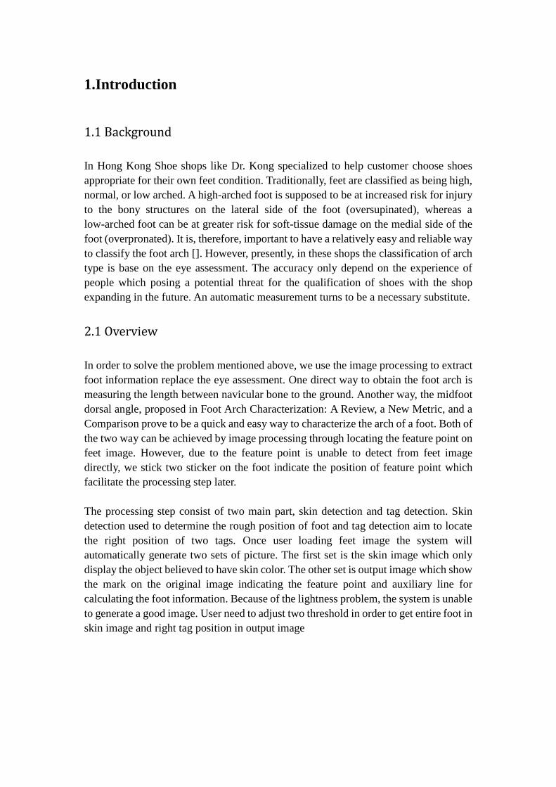
The skin detection function first find the ellipse which fitting the skin color distribution
in Cb, Cr coordinate, then mark the pixel of image which reside in the ellipse area.
figure 1: ellipse area
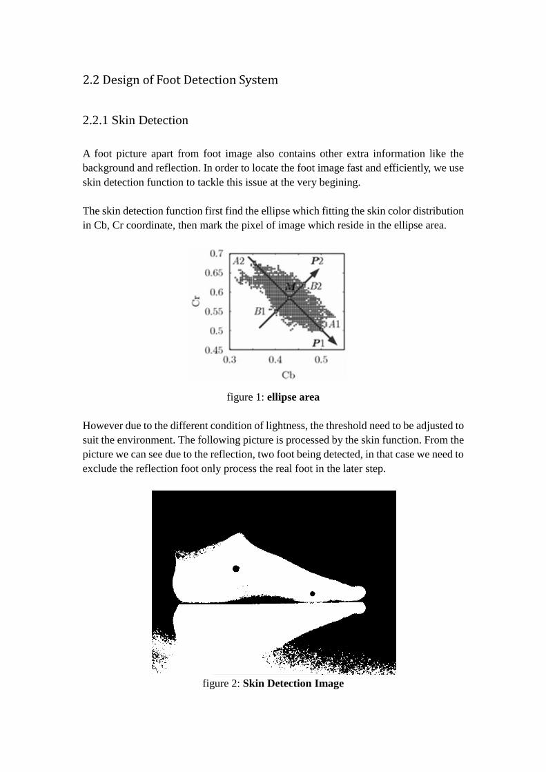
However due to the different condition of lightness, the threshold need to be adjusted to
suit the environment. The following picture is processed by the skin function. From the
picture we can see due to the reflection, two foot being detected, in that case we need to
exclude the reflection foot only process the real foot in the later step.
figure 2: Skin Detection Image
2.2.2 Boundary Line
In order to divide the picture into real foot and reflection. I use the boundary line to
break the whole skin picture into two parts. All the later procedure will only process the
image above the boundary line.
Observing the picture, you can easily find a gap between real foot and reflection, and
that's where the boundary line should be. In order to locate the gap, I search the whole
picture from bottom to top for the reflection generating a large area of white pixels in
the bottom of skin picture. Fixing the x coordinate in the left bottom of picture then
scanning each pixel along y axis until finding the black pixel. In order to determine the
pixel is the one in gap area then scanning each pixel along x axis. If the number of white
pixels is less than the threshold, we can believe the black pixel indeed locate in the gap
area. And the y coordinate of boundary line can be confirmed.
Whereas due to the foot picture may not always prefect horizontal, no line can satisfy
the threshold. Hence, we cannot scan the x axis only from one direction. Instead we first
fix two x coordinate in the bottom, one in the right bottom, the other in the left bottom.
Then repeat the procedure mentioned above, after finding each black pixel along y axis,
we scan the pixel from left to center for the left pixel and right to center for the right
pixel. In that case two y coordinates can be determined so does the boundary line. From
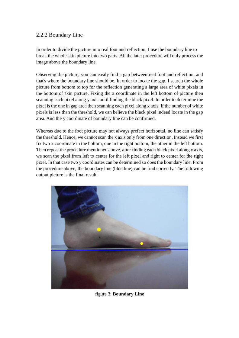
the procedure above, the boundary line (blue line) can be find correctly. The following
output picture is the final result.
figure 3: Boundary Line
2.2.3 Tag Detection
Before we process the image, two tags already stick on the foot Which form two hollow
on the foot in skin image once we adjusting the threshold to successfully generate a
complete real foot image. Two tags position then can be easily obtained.
First we need to generate another picture which only contains the edge information. We
use the built-in function cvCanny() to achieve the result. Next we use the
cvFindContours() to extract the whole contours in edge image. Then using the fit
function we can finally detect the two tags.
Because the shape of two tags is circle, cvHoughCircles() seem to be a quick and direct
way to locate the tag position. However, the experiment result is not so good, the
accuracy far from the requirement we need. A substitute way therefore need to be
proposed. We solve the problem by using the cvFitEllipse2(), the applicability is
enhanced in a large scale. For the tag now is no longer limited to the circle, but also the
ellipse.
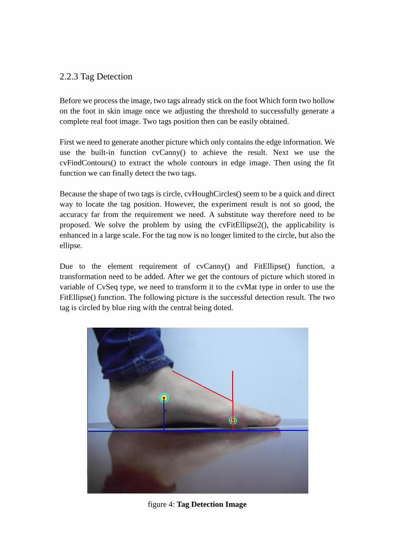
Due to the element requirement of cvCanny() and FitEllipse() function, a
transformation need to be added. After we get the contours of picture which stored in
variable of CvSeq type, we need to transform it to the cvMat type in order to use the
FitEllipse() function. The following picture is the successful detection result. The two
tag is circled by blue ring with the central being doted.
figure 4: Tag Detection Image
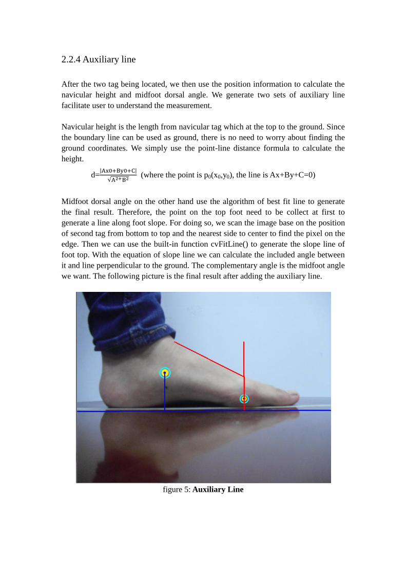
2.2.4 Auxiliary line
After the two tag being located, we then use the position information to calculate the
navicular height and midfoot dorsal angle. We generate two sets of auxiliary line
facilitate user to understand the measurement.
Navicular height is the length from navicular tag which at the top to the ground. Since
the boundary line can be used as ground, there is no need to worry about finding the
ground coordinates. We simply use the point-line distance formula to calculate the
height.
d=
(where the point is p0(x0,y0), the line is Ax+By+C=0)
Midfoot dorsal angle on the other hand use the algorithm of best fit line to generate
the final result. Therefore, the point on the top foot need to be collect at first to
generate a line along foot slope. For doing so, we scan the image base on the position
of second tag from bottom to top and the nearest side to center to find the pixel on the
edge. Then we can use the built-in function cvFitLine() to generate the slope line of
foot top. With the equation of slope line we can calculate the included angle between
it and line perpendicular to the ground. The complementary angle is the midfoot angle
we want. The following picture is the final result after adding the auxiliary line.
figure 5: Auxiliary Line
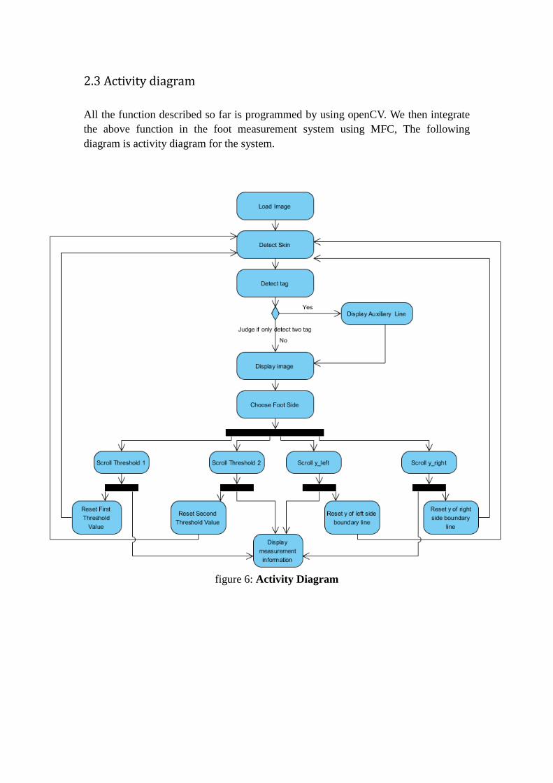
2.3 Activity diagram
All the function described so far is programmed by using openCV. We then integrate
the above function in the foot measurement system using MFC, The following
diagram is activity diagram for the system.
figure 6: Activity Diagram
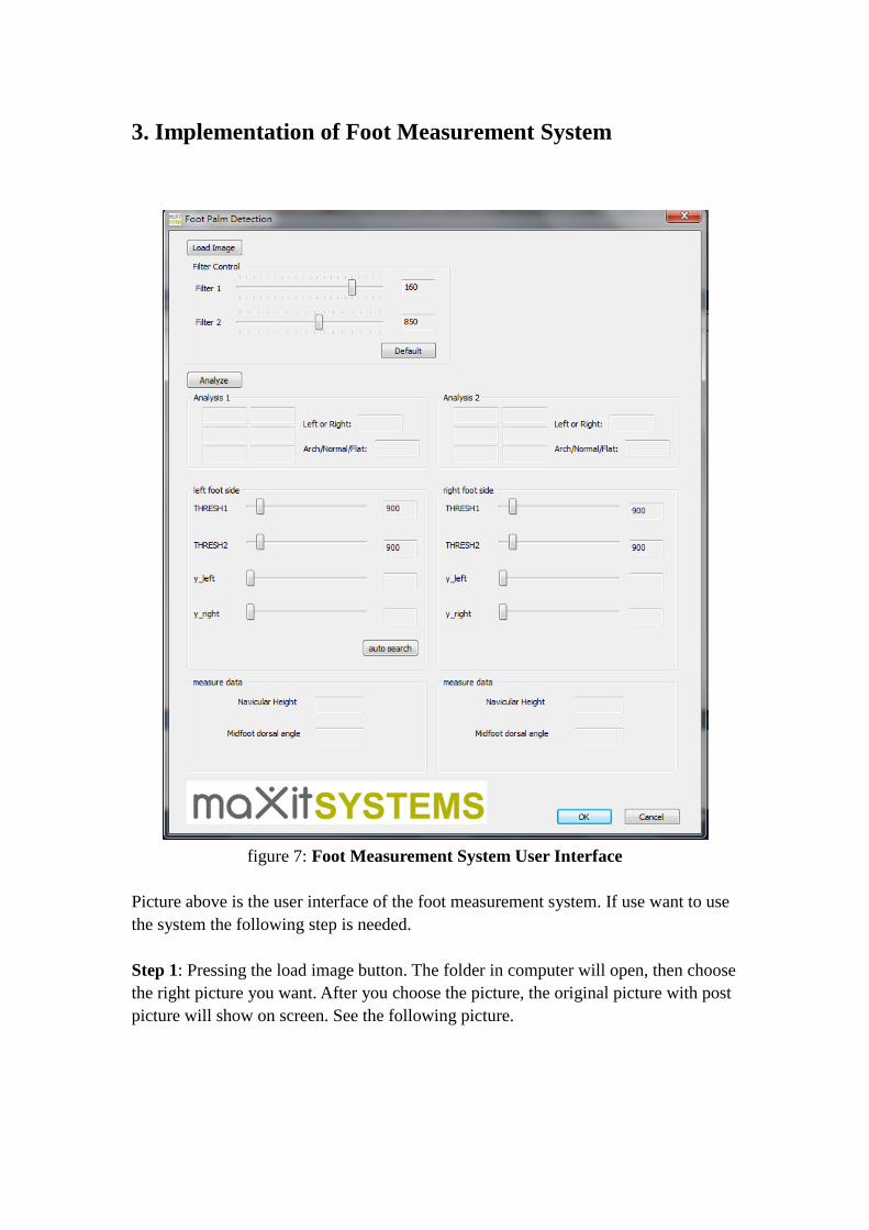
3. Implementation of Foot Measurement System
figure 7: Foot Measurement System User Interface
Picture above is the user interface of the foot measurement system. If use want to use
the system the following step is needed.
Step 1: Pressing the load image button. The folder in computer will open, then choose
the right picture you want. After you choose the picture, the original picture with post
picture will show on screen. See the following picture.
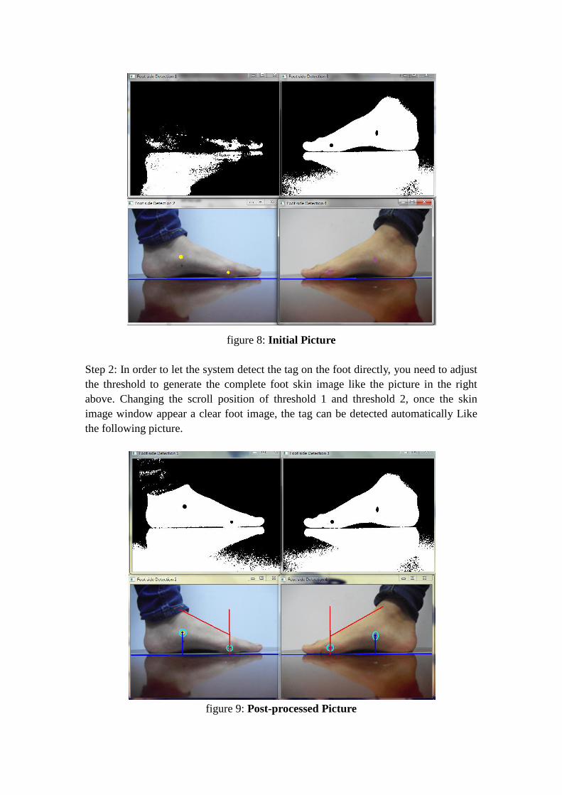
figure 8: Initial Picture
Step 2: In order to let the system detect the tag on the foot directly, you need to adjust
the threshold to generate the complete foot skin image like the picture in the right
above. Changing the scroll position of threshold 1 and threshold 2, once the skin
image window appear a clear foot image, the tag can be detected automatically Like
the following picture.
figure 9: Post-processed Picture
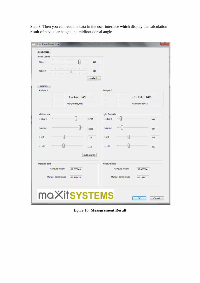
Step 3: Then you can read the data in the user interface which display the calculation
result of navicular height and midfoot dorsal angle.
figure 10: Measurement Result

4 Software and Hardware Requirements
The following is the requirement for Foot Measurement System.
4.1 Hardware
The Foot Measurement System has a lax requirements for the hardware.
4.2 Software
Software requirements include the following:
Development platform: Visual Studio
Language: C++
API: OpenCV, MFC
5. Conclusion
The Foot Measurement system integrate many algorithms for tag detection. The most
difficult problem for the system is to locate the position of feature point. Due to the
difficulty for direct detection, the tag is required to be stick on the foot which is also
the drawback of the system. However, present measure method may cannot avoid the
tag being added. The other problem of the system is it cannot detect the tag directly
without adjust the threshold of skin image. We tried to using automatic search,
whereas the calculation consumes a much time which decrease the efficiency of the
system.
Despite of the fact, the Foot Measurement System successful achieved the tag
detection and measurement of foot. Using the bulit-in function, OpenCV provide a
easy way for the shape detection and contour generation. Before we integrate the
whole function in the system, three kinds of picture actually being generate instead of
two showing in the implementation part: Skin picture, edge picture and output picture.
Those three pictures is generated one by one in the sequence above. Considering the
edge picture is no need to provide for the user, we delete it from the actual system
design. The output picture which is the original picture being added with mark and
auxiliary line cannot be generate without extract the contours in edge picture.
In conclusion, The final result generated by Foot Measurement System is satisfied and
meet the requirement being proposed at beginning.

6.Appendix
6.1 Meeting Minutes
Minutes of 1st Meeting
Date: 20/02/2012
Time: 11:30 a.m
Place: Rm.3512
Attending: Prof. Rossiter, Xu Chang
Absent: None
Recorder: Xu Chang
1. Approval of Minutes
Since this is the first meeting, there is no approval of minutes of previous meeting.
2. Report on Progress
Since this is the first meeting, there is no progress to be reported.
3. Discussion Items and Things To Do
• Project idea
• Development platform for the Foot Measurement System
4. Meeting Adjournment
The meeting was adjourned at 12:00 a.m.

Minutes of 2nd Meeting
Date: 12/03/2012
Time: 11:20 a.m
Place: Rm.3512
Attending: Prof. Rossiter, Xu Chang
Absent: None
Recorder: Xu Chang
1. Approval of Minutes
The minutes of the last meeting were approved without amendment.
2. Report on Progress
Xu Chang achieve the skin detection and generate edge picture using OpenCV .
3. Discussion Items and Things To Do
•Division the area into processing part and reflection part
•Generating the boundary line on foot image
4. Meeting Adjournment
The meeting was adjourned at11:45 a.m.

Minutes of 3rd Meeting
Date: 22/03/2012
Time: 11:00 a.m
Place: Rm.3512
Attending: Prof. Rossiter, Xu Chang
Absent: None
Recorder: Xu Chang
1. Approval of Minutes
The minutes of the last meeting were approved without amendment.
2. Report on Progress
Xu Chang achieve the naviculer height measurment.
3. Discussion Items and Things To Do
•Stick another tag on the foot facilitate the midfoot dorsal angle measurement
•Using the best fit line to generate the slope line of foot top
4. Meeting Adjournment
The meeting was adjourned at11:20 a.m.

Minutes of 4th Meeting
Date: 23/4/2012
Time: 11:00 a.m
Place: Rm.3512
Attending: Prof. Rossiter, Xu Chang
Absent: None
Recorder: Xu Chang
1. Approval of Minutes
The minutes of the last meeting were approved without amendment.
2. Report on Progress
Xu Chang finished all the function of Foot Measurement system required and
integrate the function in the system developed by MFC.
3. Discussion Thing To Do
•Finish the report
•Record a vedio
4. Meeting Adjournment
The meeting was adjourned at11:20 a.m.


![Reliability of ultrasound for measurement of selected foot ...usir.salford.ac.uk/id/eprint/33081/4/Reliability of ultrasound for measurement of...morphology [4, 5] and various foot](https://static.documents.pub/doc/80x56/5f2da072da7bbd4f13135e51/reliability-of-ultrasound-for-measurement-of-selected-foot-usir-of-ultrasound.jpg)


