Molten Salt Reactors (MSRs) For Electricity and Waste Destruction Dr. Charles Forsberg Oak Ridge National Laboratory P.O. Box 2008; Oak Ridge, TN 37831-6180 Tel: (865) 574-6783; E-mail: [email protected]Presentation of Generation IV Nuclear Energy System Concept to Office Of Nuclear Energy (DOE/NE-1) U.S. Department of Energy Washington, D.C. June 7, 2002 The submitted manuscript has been authored by a contractor of the U.S. Government under contract DE-AC05-00OR22725. Accordingly, the U.S. Government retains a nonexclusive, royalty-free license to publish or reproduce the published form of this contribution, or allow others to do so, for U.S. Government purposes. File name: MSR.NCTWG.March.2000
Transcript
Molten Salt Reactors (MSRs)For Electricity and Waste Destruction
Presentation of Generation IV Nuclear Energy System Conceptto Office Of Nuclear Energy (DOE/NE-1)
U.S. Department of EnergyWashington, D.C.
June 7, 2002
The submitted manuscript has been authored by a contractor of the U.S. Government under contract DE-AC05-00OR22725. Accordingly, the U.S. Government retains a nonexclusive, royalty-free license to publish or reproduce the published form of this contribution, or allow others to do so, for U.S. Government purposes. File name: MSR.NCTWG.March.2000
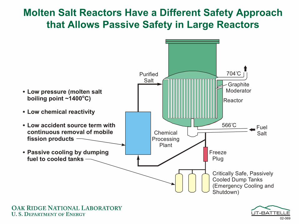
Molten Salt Reactors (MSRs) Use a Molten Salt Coolant Containing Dissolved Fuel
• Thermal Neutron Reactor− Molten salt (71.6% 7LiF, 16% BeF2, 12% ThF4, 0.4% UF4)− Fuel and fission products dissolved in fluoride salt− Graphite moderator
• The Molten Salt Breeder Reactor (MSBR) was the backup for the LMFBR (1960s)− 1000-MW(e) conceptual design developed− Lower breeding ratio (1.033) compared with the LMFBR
• Fuel cycle (primarily at reactor site)− 233U–Thorium fuel cycle (breeder fuel cycle)− Other possible fuel cycles (actinide burner, once-through)− Batch or on-line removal of selected fission products− No fuel fabrication, qualification, or irradiation damage
Traditional Molten Salt Reactor
ORNL DWG 99C-6888R
HeatExchanger
Reactor
GraphiteModerator
SecondarySalt Pump
Off-gasSystem
PrimarySalt Pump
PurifiedSalt
ChemicalProcessing
Plant
Turbo-Generator
FreezePlug
Critically Safe, Passively Cooled Dump Tanks(Emergency Cooling and Shutdown)
Steam Generator
NaBF _NaFCoolant Salt
4
72LiF _Th
Fuel Salt_BeF F _UF4 4
566 Co
704 Co
454 Co
621 Co
538 Co
The Molten Salt Reactor Experiment Demonstrated the Concept
U-235 fuel operation• Critical June 1, 1965• Full power May 23, 1966• End operation Mar 26, 1968
U-233 fuel operation• Critical Oct 2, 1968• Full power Jan 28, 1969• Reactor shutdown Dec 12, 1969
• Choice of salt depends upon mission− Breeder (low absorption cross section: Li, Be
fluorides− Waste burner (high solubility: all actinides)− Hydrogen production (low tritium production: Zr,
Na fluorides)• Extensive industrial experience
− Aluminum metal made using molten fluoride salt
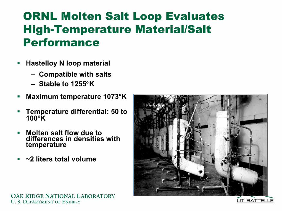
ORNL Molten Salt Loop Evaluates High-Temperature Material/Salt Performance
Hastelloy N loop material– Compatible with salts– Stable to 1255°K
Maximum temperature 1073°K
Temperature differential: 50 to 100°K
Molten salt flow due to differences in densities with temperature
~2 liters total volume
Thermal Convection Loop Establishes Compatibility for the
Most Realistic Conditions
Insert line drawing A and Picture B
Rationale for Using MSRs for Waste Burning Is Based on Engineering,
Cost, and Operational Issues• Recycle and fabrication of minor-actinide solid fuels are
very expensive and difficult• Waste burning has excessive impacts on conventional
reactors (high actinide inventory to destruction rate)• Molten Salt Reactors
− Add actinides to salt− Actinides remain in salt until full burnout − Fission products removed from salt− For waste burner applications, ~10% of nuclear
electricity from MSRs used for waste destruction• R&D is required to define the best waste burning strategy
The Proliferation-Resistant Characteristics of the MSR Are
Different Than Those of Other Systems
• Low total fissile inventory• With added 238U, 233U made non-weapons-
usable• Very poor plutonium isotopics (primarily
242Pu)
Advanced High-Temperature Reactor (AHTR):(Solid Fuel and Salt Coolant for Hydrogen Production)
• Goals− Hydrogen production− Efficient electricity production
• Requirements for hydrogen production define reactor design− Low pressure− Heat delivered at a high, almost-constant temperature− No tritium− Isolation of reactor from chemical facility
• AHTR design characteristics− Solid coated-particle fuel (similar to gas-cooled reactors)− Molten salt coolant (Na/Zr fluoride, etc.)
The AHTR Uses a Multi-Reheat Brayton Cycle for High-Efficiency Electricity Production


![Electricity generation potential from solid waste in three … · 2018-12-20 · Electricity generation potential from solid waste in three Colombian municipalities [112] TecnoLógicas,](https://static.documents.pub/doc/80x56/5f0aec537e708231d42e0134/electricity-generation-potential-from-solid-waste-in-three-2018-12-20-electricity.jpg)


