+ All Categories
Home > Documents > Foundation Engineering, Inc. Memorandum Professional ...

Foundation Engineering, Inc. Memorandum Professional ...

Date post: 15-Oct-2021
Category:
Upload: others
View: 2 times
Download: 0 times
Share this document with a friend
29
Foundation Engineering, Inc. Memorandum Professional Geotechnical Services Date: To: From: Subject: Project: July 16, 2020 Charles Wright, P.E. Senior Associate Engineer Kennedy Jenks Erin J. Gillaspie, P.E. James K. Maitland, P.E., G.E. Geotechnical Investigation City of Albany, Class A Biosolids Composting Project Project No.: 2191137 We have completed above-referenced project. below. the requested geotechnical investigation for the Details of our findings and recommendations are provided BACKGROUND The City of Albany plans to build a new biosolids processing facility at its Water Reclamation Facility (WRF) Solids Handling site near the intersection of NE Willamette Avenue and NE Davidson Street in Albany, Oregon. The site location is shown in Figure 1 A (Appendix A). The planned site layout is shown in Figure 2A (Appendix Al and an aerial photograph showing existing facilities is shown in Figure 3A (Appendix Al. The WRF is located immediately south of the Willamette River. New fill will be required to raise the site above the 1 00-year flood elevation. The City of Albany (City) is the owner. Kennedy Jenks is the prime consultant and retained Foundation Engineering as the geotechnical consultant. Our scope of work was outlined in a proposal dated September 1 7, 201 9, and authorized by a signed agreement dated January 6, 2020. Foundation Engineering has completed previous investigations within the existing facility. Results from those investigations have been used to supplement the current work, where appropriate. Primary current and future project elements include: A new ± 9,000 square foot (SF) Composting Building with a fabric-type cover over the composting system. This type of structure with captions provided by Kennedy Jenks is depicted in Photo 1A (Appendix A). The Composting Building will have a slab-on-grade concrete floor over ± 3 to 6 feet of new fill. The structure will have a concrete backwall and large concrete ecology block side walls and dividers. A future Secondary Composting Building similar to the Composting Building built on ± 1 foot of new fill. 820 NW Cornell Avenue Corvallis, Oregon 97330 541-757-7645 7857 SW Cirrus Drive, Bldg 24 Beaverton, Oregon 97008 503-643-1541
Transcript

Foundation Engineering, Inc. Memorandum Professional Geotechnical Services

Date:

To:

From:

Subject:

Project:

July 16, 2020

Charles Wright, P.E. Senior Associate Engineer Kennedy Jenks

Erin J. Gillaspie, P.E. James K. Maitland, P.E., G.E.

Geotechnical Investigation

City of Albany, Class A Biosolids Composting Project Project No.: 2191137

We have completed above-referenced project. below.

the requested geotechnical investigation for the Details of our findings and recommendations are provided

BACKGROUND

The City of Albany plans to build a new biosolids processing facility at its Water Reclamation Facility (WRF) Solids Handling site near the intersection of NE Willamette Avenue and NE Davidson Street in Albany, Oregon. The site location is shown in Figure 1 A (Appendix A).

The planned site layout is shown in Figure 2A (Appendix Al and an aerial photograph showing existing facilities is shown in Figure 3A (Appendix Al. The WRF is located immediately south of the Willamette River. New fill will be required to raise the site above the 1 00-year flood elevation.

The City of Albany (City) is the owner. Kennedy Jenks is the prime consultant and retained Foundation Engineering as the geotechnical consultant. Our scope of work was outlined in a proposal dated September 1 7, 201 9, and authorized by a signed agreement dated January 6, 2020. Foundation Engineering has completed previous investigations within the existing facility. Results from those investigations have been used to supplement the current work, where appropriate.

Primary current and future project elements include:

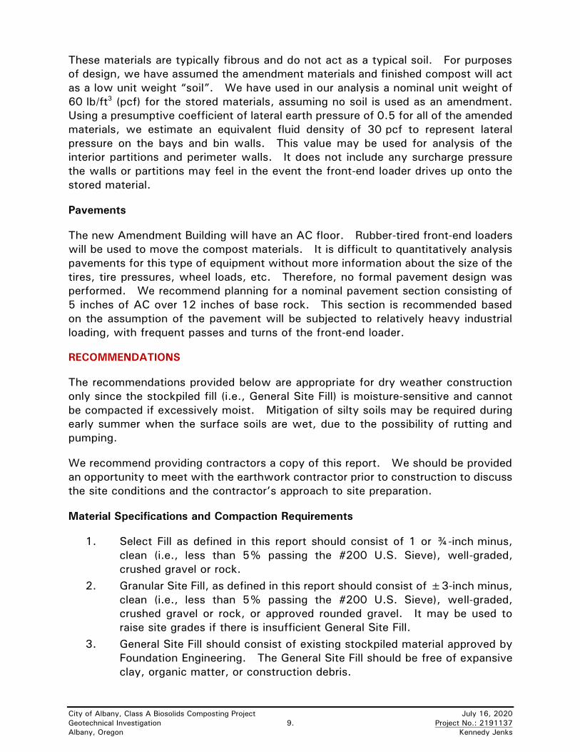
• A new ± 9,000 square foot (SF) Composting Building with a fabric-type cover over the composting system. This type of structure with captions provided by Kennedy Jenks is depicted in Photo 1 A (Appendix A). The Composting Building will have a slab-on-grade concrete floor over ± 3 to 6 feet of new fill. The structure will have a concrete backwall and large concrete ecology block side walls and dividers.

• A future Secondary Composting Building similar to the Composting Building built on ± 1 foot of new fill.

820 NW Cornell Avenue • Corvallis, Oregon 97330 • 541-757-7645 7857 SW Cirrus Drive, Bldg 24 • Beaverton, Oregon 97008 • 503-643-1541

City of Albany, Class A Biosolids Composting Project July 16, 2020

Geotechnical Investigation 2. Project No.: 2191137

Albany, Oregon Kennedy Jenks

• A new ±9,000-SF Amendment Building with a fabric-type cover. This type

of structure with captions provided by Kennedy Jenks is depicted in Photo 2A

(Appendix A). The Amendment Building will be supported on columns with

spread footings and have an asphaltic concrete (AC) paved floor. No new fill

is anticipated for the Amendment Building.

• A new Biofilter with a concrete slab-on-grade and short curbs built on ±4 to

6 feet of new fill north of the Composting Building.

FIELD EXPLORATION

We excavated six exploratory test pits (TP-1 through TP-6) at the site on

January 8, 2020, using a Takeuchi TB290 mini excavator. The test pit locations

were selected, in part, to avoid underground utilities and paved areas. The

approximate test pit locations are shown on Figure 2A and 3A (Appendix A).

The test pits extended to maximum depths ranging from ±4.5 to 11 feet. Disturbed

soil samples were obtained at selected depths for possible laboratory testing and

observation in our office. The soil profiles, sampling depths and strength

measurements are summarized on the test pit logs (Appendix B). A deeper soil

profile was estimated based on previous borings at the site. The subsurface

conditions are discussed below.

LABORATORY TESTING

The laboratory work included moisture content and Atterberg Limits tests on selected

soil samples to help classify the soils according to the Unified Soil Classification

System (USCS) and estimate their overall engineering properties. Laboratory tests

were limited to the fine-grained soils encountered in the current explorations.

Non-tested samples were visually classified in accordance with ASTM D2488-09a

and ASTM D2487-11. The laboratory test results are summarized in Table 1.

Table 1. Laboratory Test Results

Sample Sample

Depth (ft.)

Moisture

Content (%)

Liquid

Limit

Plastic

Limit

Plasticity

Index

USCS

Designation

S-4-2 4.0 – 5.0 40.3 52 17 35 CH

S-6-1 3.0 – 4.0 31.0 57 30 27 CH

City of Albany, Class A Biosolids Composting Project July 16, 2020

Geotechnical Investigation 3. Project No.: 2191137

Albany, Oregon Kennedy Jenks

SITE CONDITIONS

Surface Conditions and Topography

AC pavement surrounds the existing clarifiers and extends into the portion of the site

where the proposed structures are planned. The western portion of the site is

typically covered with crushed gravel and/or grass. A large stockpile of soil

currently occupies the northeast portion the planned composting facility. Site

conditions at the time of our field exploration are shown in Photos 3A and 4A

(Appendix A).

Most of the planned composting site is relatively flat but slopes down to the north

along the north side of the WRF site (i.e., the south bank of the Willamette River).

A topographic map provided by Kennedy Jenks indicates typical ground surface

elevations in the vicinity of the proposed Composting and Biofilter structures ranging

from ±El. 202 in the south to ±El. 198 in the northeast. The ground surface slopes

down ±3:1 (H:V) to the north and northwest, and the ground surface at TP-1 is

±El. 198. The ground surface at the auxiliary area (i.e., in the vicinity of TP-6)

slopes down ±15:1 (H:V) to the northeast, with ground surface elevations ranging

from ±El. 201 to 212.

Subsurface Conditions

The following soil units were encountered in the test pits. Additional description of

the individual layers is provided in the logs (Appendix B).

Silty sandy gravel (fill). Test pits TP-1 through TP-5 encountered surficial silty sandy

gravel (fill). TP-6 encountered this unit below ±4 feet. The gravel fill was typically

moist, medium dense to very dense, and subrounded to rounded. The gravel

becomes clayey with depth at some locations, and often contains cobbles. At TP-2

and TP-4, the site fill contains varying amounts of scattered construction debris,

wood, and cobbles. The site fill extends to the maximum depth of most test pits.

The gravel below ±6 feet in TP-2 contains some cobbles up to ±10 inches in

diameter and may represent native alluvium.

Clay to silty clay (fill). Brown, medium to high plasticity silty clay was encountered

to ±4 feet in TP-6. High plasticity clay was also encountered from ±4.5 to

6.5 feet (the limit of the test pit) in TP-4. These fill units were moist and stiff to

very stiff at the time of the exploration.

A review of previous explorations by Foundation Engineering and others suggests

the existing fill is underlain by fine-grained alluvium consisting of primarily clay to

sandy clay to at least ±70 feet.

Stockpiled fill. The existing stockpile is planned for use as new General Site Fill.

This material was generated during a recent sewerline project and consists of variable

mixtures of silt, sand, gravel, and cobbles.

City of Albany, Class A Biosolids Composting Project July 16, 2020

Geotechnical Investigation 4. Project No.: 2191137

Albany, Oregon Kennedy Jenks

Ground Water. No seepage or groundwater was encountered in the explorations.

We anticipate a good hydraulic connection between the ground water elevation at

the site and the water elevation in the Willamette River. Therefore, the water level

beneath the site will fluctuate seasonally and closely correspond to the water level

in the river. Well logs suggest the static ground water level at the site is ±20 to

25 feet below current grades. Based on the lack of planned below-grade structures

and the available information, ground water should not be a geotechnical issue for

this project.

DISCUSSION OF GEOTECHNICAL CONSIDERATIONS

A general discussion of geotechnical considerations is provided in this section as

they pertain to the proposed expansion. Specific construction recommendations for

these items are provided in the recommendations section.

Re-Use of Stockpiled Fill as General Site Fill

Up to ±6 feet of fill will be required to raise the site grade above the100-year flood

plain where new structures are planned. The City proposes to use the existing

stockpiled fill for the build of the site grading. Based on our evaluation of the

stockpiled material, we believe most of it will be suitable as General Site Fill, as

described in the Recommendations section of this report. However, the fill is

variable. Therefore, the fill should be re-evaluated as it is excavated as well as prior

to placement to confirm its condition and suitability. The fill should be free of

construction debris, organics, expansive clay, and/or other deleterious materials.

Adequate moisture-conditioning and compaction of the fill should also be confirmed

by a Foundation Engineering representative.

The stockpiled fill contains significant fine-grained soil. These soils will be

moisture-sensitive and will soften considerably when wet and disturbed by

construction traffic. Also, adequate compaction of the new fill will only be possible

during dry weather, when moisture-conditioning (aeration) is possible. Therefore,

we recommend completing the site grading and foundation construction during the

dry summer months (typically mid-June through mid-October).

Beneath new structures, the approved General Site Fill should also be capped with

compacted crushed gravel or rock (i.e., Select Fill, as defined below) to construct a

building pad (see further discussions below).

City of Albany, Class A Biosolids Composting Project July 16, 2020

Geotechnical Investigation 5. Project No.: 2191137

Albany, Oregon Kennedy Jenks

Expansive Soils

Atterberg Limits tests (see Table 1, above) indicate the fine-grained fil encountered

at TP-4 has a Liquid Limit of 52 and a Plasticity Index (PI) of 35. These limits

correspond to a high plasticity clay (CH) designation according to the Unified Soil

Classification System (USCS). CH soils are typically associated with a relatively

high risk of swelling and shrinking due to seasonal changes in moisture content.

However, at TP-4, the plastic clay is buried under ±4 feet of gravel and addition site

fill is planned. Therefore, the risk of subgrade movement due to seasonal changes

in moisture is minor. Future development in the grassy field surrounding TP-6 will

likely require significant grading. The need for any mitigation of expansive soil at

that location should be confirmed when the FFE and foundation depths are

confirmed.

Full mitigation of the high plasticity clay would require full-depth removal and

replacement with non-expansive soil (e.g., crushed rock or gravel). However, full

mitigation may be costly depending on the depth and extent of the high plasticity

clay, and we do not anticipate the planned structures will be particularly sensitive to

minor differential movements. Therefore, we have recommended partial mitigation

measures (described below) if high plasticity material is exposed at the subgrade

level of slabs, foundations, or pavements to help further mitigate the risk to

structures.

Existing Site Fill

The existing granular fill observed in the test pits at or below the proposed foundation

level appears suitable to support new foundations and slabs in its current state.

However, field confirmation of the suitability of the fill should be made at the time

of construction because it may be more variable across the site. The existing clay

fill encountered in TP-4 and TP-6, has relatively high plasticity and expansive if similar

clay fill is encountered at the foundation level for any of the new structures, it should

be mitigated by overexcavation and placement of at least 2 feet of compacted

granular fill, as detailed in the Recommendations section of this report.

Foundation Soils

The soil encountered at the anticipated foundation elevation (where little or no new

fill is anticipated) consists of silty sandy gravel. The foundation soils at the time of

the exploration were typically moist to wet and medium dense to very dense. The

existing foundation soils are suitable for supporting the planned buildings using

conventional shallow spread footings and continuous wall footings. Existing

granular fill at the subgrade level of planned structures should be compacted prior to

construction.

In areas where additional fill is required for site grading, the ground surface should

be stripped of any organics, if present, and recompacted prior to pacing ne fill. New

fill should consist of Select Fill or approved General Site Fill, placed and compacted

as described in the Recommendations section of this report.

City of Albany, Class A Biosolids Composting Project July 16, 2020

Geotechnical Investigation 6. Project No.: 2191137

Albany, Oregon Kennedy Jenks

Footings should also be underlain by ±12 inches of Select Fill. This fill thickness

may need to be reduced to ±6 inches beneath the Amendment Building footings (to

be confirmed during construction).

Building pads consisting of a minimum of 12 inches of Select Fill should be

constructed beneath all new structures.

ENGINEERING ANALYSIS AND CONSTRUCTION CONSIDERATIONS

SEISMIC DESIGN

Site Response Spectrum. We developed a design spectral acceleration response

spectrum for the site in accordance with the Oregon Structural Specialty Code

(OSSC 2019), which is based on Section 1613 of the International Building Code

(IBC 2018) and ASCE 7-16. Our current and previous explorations and local water

well logs indicate the upper ±100 feet of the subsurface profile consist primarily of

alternating layers of stiff fine-grained soil (i.e., silts and clays). Therefore, we have

concluded a Site Class D (stiff soil profile) is appropriate for design.

When developing the design response spectrum for a Site Class D, ASCE 7-16

Section 11.4.8 requires a ground motion hazard analysis be performed in accordance

with ASCE 7-16 Section 21.2 at sites where the 1.0 second spectral acceleration on

rock (S1) is greater than or equal to 0.2g. However, an exception in Section 11.4.8

stipulates a ground motion hazard analysis is not required when the seismic response

coefficient Cs is calculated based on Eq. 12.8-2 for values of T ≤ 1.5TS and taken as

equal to 1.5 times the value computed using either Eq. 12.8-3 for T > 1.5TS or

Eq. 12.8-4 for T ≥ 1.5TL (where TS = SD1/SDS and TL is the long-period transition

period shown on Figure 22-14 in Chapter 22). The TL value for Oregon is

16 seconds.

The adjustment in the Cs value is intended to better model long-period spectral

accelerations for softer soils coupled with strong ground motions. However, the

adjustment applies only to the design of long-period structures (i.e., typically

structures with a height of five stories or greater). For the proposed ±20-foot tall

structures, we anticipate the period of interest will be less than 1.5TS and no Cs

adjustment will be necessary when using the exception in Section 11.4.8.

Therefore, we developed the site response spectrum shown on Figure 4A

(Appendix A) using the mapped risk-targeted maximum considered earthquake

(MCER) ground motions and the general procedure in Section 11.4.6 with Fa selected

based on Table 11.4-1 and Fv selected based on Table 11.4-2. The risk-targeted

maximum considered earthquake (MCER) ground motions were obtained from

modified USGS 2014 maps with a 2% probability of exceedance in 50 years

(i.e., a ±2,475-year return period). The modifications include factors to adjust the

spectral accelerations to account for directivity and risk.

City of Albany, Class A Biosolids Composting Project July 16, 2020

Geotechnical Investigation 7. Project No.: 2191137

Albany, Oregon Kennedy Jenks

Liquefaction and Liquefaction-Induced Settlement. Liquefiable soils typically consist

of saturated, loose sand and non-plastic silt. The risk of liquefaction and resulting

settlement or lateral spread is considered very low due to the density of the shallow

granular fill and the stiffness and plasticity of the deeper, (native) fine-grained soils

that underlie the site.

Discussion of Anticipated Loads, Foundation Conditions, and Foundation Type

Anticipated foundation loads were not available at the time this report was prepared.

However, we assumed the fabric-style structures will have a maximum column loads

not exceeding 50 kips. We understand the perimeter of the structures will consist

of precast concrete blocks to form bays that can be accessed from several directions.

Based on the existing site conditions, we anticipate conventional shallow foundations

(i.e., spread footings and continuous strip footings) are adequate to support the new

structures. We anticipate resistance to wind uplift, rather than structural load, will

likely dictate the size of the foundations.

Bearing Capacity

The soil stockpiled in the northeastern portion of the site is expected to be used as

General Site Fill. This stockpile represents material generated from local sewerline

trenching consists of a variable mixture of silt, sand, clay, and gravel with scattered

cobbles. Kennedy Jenks estimated that ±3 to 6 feet of new site fill will be required

under the new Composting Building and ±1 foot of site fill will be required under the

future Secondary Composting Building. The new Biofilter will require ±4 to 6 feet

of new site fill. No significant filling is anticipated for the Amendment Building.

Assuming the stockpiled material is placed and compacted as specified herein, we

recommend a presumptive (allowable) bearing capacity of 2,000 lb/ft2 (psf) for the

design of new footings. For planning purposes, this value may also be used for

future construction in the grassy field (in the vicinity of TP-6). However, at that

location, a significant amount of site grading will be required. Therefore, the

allowable bearing pressure for new construction is this area should be confirmed

based on the actual foundation conditions.

No significant new site fill is planned under the Amendment Building. If desired, an

allowable bearing pressure of 3,000 psf may be used for footing design of the

Amendment Building.

City of Albany, Class A Biosolids Composting Project July 16, 2020

Geotechnical Investigation 8. Project No.: 2191137

Albany, Oregon Kennedy Jenks

Settlement

The type of structures, construction materials, and intended use of the new facility

suggest the new structures are not particularly settlement sensitive. Settlement due

to consolidation of clay beneath the new building foundations is expected to be

relatively small given the anticipated modest foundation loads, relatively small live

loads from the stockpiled compost, and the observed stiffness of the fine-grained fill

in TP-4. For the allowable bearing pressures discussed above, we anticipate a

maximum foundation settlement of ±½ inch or less where the foundations are

underlain by fine-grained soil. No appreciable settlement is expected where

foundations are underlain by dense gravel. Therefore, differential settlement

between adjacent footings may also be up to ±½ inch.

Sliding Coefficient and Passive Resistance for Footings

We have recommended below that all new footings be underlain by a nominal 6 to

12 inches of compacted Select Fill, as defined below. A sliding coefficient of 0.5 is

recommended to analyze the sliding resistance of new footings constructed on the

compacted Select Fill.

Passive resistance of the soil in front of buried footings was calculated as an

equivalent fluid density. An equivalent fluid density of 150 pcf is recommended for

the evaluation of new footings, assuming the backfill around the footings will consist

of compacted Select Fill. A factor of safety has been applied to these values, since

it is unlikely the footings will move lateral enough to mobilize the full passive

resistance.

Floor Slab Design

We recommend the concrete floor slab for the Composting Building and Biofilter be

designed using a modulus of subgrade reaction of 200 lb/in3 (pci). This value

assumes the floor slab will be constructed on a minimum of 12 inches of compacted

crushed rock (i.e., Select Fill) over approved General Site Fill or over dense gravel

(existing site fill). We recommend the concrete floor slab be reinforced due to

anticipated heavy wheel loads from front-end loaders.

Lateral Loads

The materials to be stored will consist of raw compost (a mix of biosolids and carbon

amendment) that will be placed in bays of the Composting Building. The carbon

amendment (woodchips and yard debris) will be stored in the Amendment Building,

as well as finished compost.

City of Albany, Class A Biosolids Composting Project July 16, 2020

Geotechnical Investigation 9. Project No.: 2191137

Albany, Oregon Kennedy Jenks

These materials are typically fibrous and do not act as a typical soil. For purposes

of design, we have assumed the amendment materials and finished compost will act

as a low unit weight “soil”. We have used in our analysis a nominal unit weight of

60 lb/ft3 (pcf) for the stored materials, assuming no soil is used as an amendment.

Using a presumptive coefficient of lateral earth pressure of 0.5 for all of the amended

materials, we estimate an equivalent fluid density of 30 pcf to represent lateral

pressure on the bays and bin walls. This value may be used for analysis of the

interior partitions and perimeter walls. It does not include any surcharge pressure

the walls or partitions may feel in the event the front-end loader drives up onto the

stored material.

Pavements

The new Amendment Building will have an AC floor. Rubber-tired front-end loaders

will be used to move the compost materials. It is difficult to quantitatively analysis

pavements for this type of equipment without more information about the size of the

tires, tire pressures, wheel loads, etc. Therefore, no formal pavement design was

performed. We recommend planning for a nominal pavement section consisting of

5 inches of AC over 12 inches of base rock. This section is recommended based

on the assumption of the pavement will be subjected to relatively heavy industrial

loading, with frequent passes and turns of the front-end loader.

RECOMMENDATIONS

The recommendations provided below are appropriate for dry weather construction

only since the stockpiled fill (i.e., General Site Fill) is moisture-sensitive and cannot

be compacted if excessively moist. Mitigation of silty soils may be required during

early summer when the surface soils are wet, due to the possibility of rutting and

pumping.

We recommend providing contractors a copy of this report. We should be provided

an opportunity to meet with the earthwork contractor prior to construction to discuss

the site conditions and the contractor’s approach to site preparation.

Material Specifications and Compaction Requirements

1. Select Fill as defined in this report should consist of 1 or ¾-inch minus,

clean (i.e., less than 5% passing the #200 U.S. Sieve), well-graded,

crushed gravel or rock.

2. Granular Site Fill, as defined in this report should consist of ±3-inch minus,

clean (i.e., less than 5% passing the #200 U.S. Sieve), well-graded,

crushed gravel or rock, or approved rounded gravel. It may be used to

raise site grades if there is insufficient General Site Fill.

3. General Site Fill should consist of existing stockpiled material approved by

Foundation Engineering. The General Site Fill should be free of expansive

clay, organic matter, or construction debris.

City of Albany, Class A Biosolids Composting Project July 16, 2020

Geotechnical Investigation 10. Project No.: 2191137

Albany, Oregon Kennedy Jenks

4. The Separation Geotextile should meet the minimum requirements of an

AASHTO M 288-17 geotextile for separation and have Mean Average Roll

Value (MARV) strength properties meeting the requirements of an AASHTO

M 288-17 Class 2, woven geotextile. We should be provided a

specification sheet on the selected geotextile for approval prior to delivery

to the site.

5. Compact all fill in loose lifts not exceeding 12 inches. Thinner lifts of

8 inches or less will be required if light or hand-operated equipment is used.

Compact all fill to a minimum of 95% relative compaction, unless otherwise

specified. The maximum dry density of ASTM D 698 should be used as

the standard for estimating relative compaction, unless otherwise specified.

Field density tests should be run frequently to confirm adequate

compaction of the fill.

6. The stockpiled General Site Fill is variable and contains oversized gravels

and cobbles. Therefore, confirmation of adequate compaction of this

material will require proof rolling. The proof rolling should be completed

using a loaded water truck, dump truck or other approved vehicle and

should be observed by a Foundation Engineering representative.

7. Shoring should be provided in any utility trenches according to OR-OSHA

Standards to protect workers from sloughing or caving soils. Soil

conditions encountered in the test pits typically correspond to OSHA Type

C soils. Shoring and worker safety are the sole responsibility of the

contractor.

Foundation Design and Construction

Foundation design and construction for all of the structures should be in general

accordance with the following recommendations.

8. Design the foundations using an allowable bearing pressure of 2,000 psf.

This value may be used for all new footings and for interior partitions and

perimeter walls built using precast eco-blocks. An allowable bearing

pressure of 3,000 psf may be used for the Amendment Building, if no

General Site Fill is placed in this area.

9. Assume total and differential settlements of ½ inch or less, if the footings

are designed and built as specified herein.

10. Design the structure using OSSC 2019 seismic parameters and response

spectrum shown in Figure 4A (Appendix A).

11. Where practical, embed the base of all concrete ecology blocks at least

1 foot below finish grades. If blocks are to rest directly on the floor slab,

they should be designed to resist sliding due to lateral forces from the

retained materials. We assume new CIP footings will be extend a nominal

2 feet below floor slabs or AC surfaces.

City of Albany, Class A Biosolids Composting Project July 16, 2020

Geotechnical Investigation 11. Project No.: 2191137

Albany, Oregon Kennedy Jenks

12. Provide at least 12 inches of compacted Select Fill under new footings and

ecology block walls underlain by General Site Fill. The Select Fill should

extend at least 6 inches beyond the edges of all footings and blocks. The

Select Fill beneath the footings may be reduced to a leveling course (±4

to 6 inches thick) where the footings extend to existing dense gravel site

fill (e.g., at the Amendment Building). Any reduction of the Select Fill

should be confirmed during construction.

13. Use an equivalent fluid density of 30 pcf to model the lateral pressure from

stored materials on interior partitions or bins and perimeter walls. This

value is likely an upper bound, but does not include any surcharge that

could occur if the front-end loader is driven onto the stored material, near

the bays or the perimeter walls.

14. Use a modulus of subgrade reaction, ks, of 200 pci for floor slab design.

This value assumes the slabs will be supported on a minimum of 12 inches

of compacted Select Fill underlain by compacted subgrade. Reinforce all

floor slabs to reduce the risk of cracking and warping. The thickness of

the Select Fill may be reduced to 6 inches under the Amendment Building,

if the subgrade condition is confirmed by a Foundation Engineering

representative.

Site Preparation for New Structures. We recommend the site grading be completed

in dry weather only. The soil stockpiled on site contains a significant amount of

fines. Proper moisture-conditioning and compaction will require dry weather

conditions. The site preparation should be done using the following guidelines:

15. Strip the foundation areas as required to remove concentrated roots and

sod, existing pavements, or other construction debris. Dispose of all

strippings outside of construction areas. Deeper stripping or excavation

may be required if loose/unsuitable fill or debris is encountered. The

condition of the stripped subgrade should be evaluated at the time of

construction.

16. Excavate the existing backfill in the exploratory test pits that are within

building footprints and replace with compacted Select Fill. Figures 2A and

3A show the approximate locations of the test pits. A Foundation

Engineering representative is available to locate these test pits, if needed.

17. Compact the stripped surface prior to placing backfill. Proof roll the

prepared subgrade prior to placing any new site fill. Overexcavate any

disturbed or pumping areas and replace it with approved General Site Fill,

Select Fill, or Granular Site Fill (if additional imported fill is required).

City of Albany, Class A Biosolids Composting Project July 16, 2020

Geotechnical Investigation 12. Project No.: 2191137

Albany, Oregon Kennedy Jenks

18. Where new site fill is required, place General Site Fill or Granular Site Fill in

lifts and mechanically compact as specified above during dry weather only.

The suitability of the stockpiled fill for use as General Site Fill should be

confirmed by Foundation Engineering as it is placed. If needed, remove

pockets of plastic clay, debris, or over-sized cobbles. Individual lifts

should be constructed at slopes no steeper than 10:1 (H:V). Where

practical, finished slopes should be graded at 3:1 (H:V), or flatter. In areas

of limited space, the finished slope can be steepened to 2:1 (H:V).

19. Proof roll the new fill as it is placed using an approved truck or vehicle.

Where more than 2 feet of fill is required, the fill should be proof rolled in

lifts. The proof roll should be observed by Foundation Engineering. If

excessive deflection or rutting is observed, the fill should be removed,

moisture-conditioned (dried), re-compacted, and proof rolled again.

20. Cap General Site Fill and Granular Site Fill under all floor slabs or AC

surfaces with at least 12 inches of Select Fill. Compact the Select Fill as

recommended above. Do not allow heavy trucks on the building pads.

Where no General Site Fill is required, the thickness of the Select Fill

beneath the slab or AC surface can be reduced to 6 inches, if the subgrade

consists of dense gravel (to be confirmed by Foundation Engineering).

21. Excavate for the footings using a hoe equipped with a smooth bucket to

minimize subgrade disturbance. The excavations should extend at least

6 inches beyond the edges of the footings. The required excavation

depths and the condition of the soil should be confirmed at the time of

construction by a Foundation Engineering representative prior to backfilling.

22. Place at least 12 inches of compacted Select Fill under new footings or

blocks. This thickness can be reduced to a leveling course (4 to 6 inches

thick) in areas underlain by existing dense gravel.

23. Grade the finished ground surface surrounding the buildings to promote

runoff away from the foundations.

Foundation Drainage. The static ground water table is expected to be well below the

current limits of grading and excavations. Therefore, ground water is not expected

to be a significant issue, except for possible perched water during periods of

sustained rainfall.

We understand the new composting building will be surrounded partially by relatively

impervious pavement and partially by gravel surfaces. The pavement surfaces will

be flush with the interior floors to allow loaders and other equipment to drive into

the composting building. The exterior pavements surface will be sloped to promote

runoff away from the foundations. Based on the anticipated drainage characteristics

of the existing site fill, the planned sloping of exterior surfaces, and the intended use

of the facility, we do not anticipate the need for foundation drainage.

City of Albany, Class A Biosolids Composting Project July 16, 2020

Geotechnical Investigation 13. Project No.: 2191137

Albany, Oregon Kennedy Jenks

Pavement Subgrade Preparation and Construction (Dry Weather)

24. Strip the pavement areas as required to remove concentrated roots and

sod, existing pavements, or other construction debris. Dispose of all

strippings outside of construction areas.

25. Prepare, compact, and test the subgrade as specified above.

26. Place a Separation Geotextile on the prepared subgrade that meets the

requirements specified above. The geotextile should be laid smooth,

without wrinkles or folds in the direction of construction traffic. Overlap

adjacent rolls a minimum of 2 feet. Pin fabric overlaps or place the building

pad fill in a manner that will not separate the overlap during construction.

Seams that have separated will require removal of the base rock to

establish the required overlap.

27. Provide a nominal section of 5 inches of AC over 12 inches of Select Fill

for those areas subject to heavy front-end loader traffic.

CONSTRUCTION OBSERVATION/TESTING

Foundation Engineering should be provided the opportunity to review all drawings

and specifications that pertain to site preparation and foundation construction. Site

preparation will require field confirmation of subgrade conditions and suitability of

the existing stockpiled fill. Mitigation of any unsuitable fill, soft soils, ground water

infiltration, or subgrade pumping will also require engineering review and judgment.

That judgment should be provided by one of our representatives. Frequent field

density tests should be run on all engineered fill, subgrade, and base rock (where

applicable). In areas that cannot be tested, the adequacy of the compacted material

should be established by proof rolls. We recommend that we be retained to provide

the necessary construction observation.

VARIATION OF SUBSURFACE CONDITIONS, USE OF THIS REPORT, AND WARRANTY

The analysis, conclusions, and recommendations contained herein assume the

subsurface profiles encountered in the test pits are representative of the site

conditions. No changes in the enclosed recommendations should be made without

our approval. We will assume no responsibility or liability for any engineering

judgment, inspection, or testing performed by others.

This report was prepared for the exclusive use of Kennedy Jenks and other design

consultants for the City of Albany, Class A Biosolids Composting project in

Albany, Oregon. Information contained herein should not be used for other sites or

for unanticipated construction without our written consent. This report is intended

for planning and design purposes. Contractors using this information to estimate

construction quantities, production rates, or costs do so at their own risk.

City of Albany, Class A Biosolids Composting Project July 16, 2020

Geotechnical Investigation 14. Project No.: 2191137

Albany, Oregon Kennedy Jenks

Our services do not include any survey or assessment of potential surface

contamination or contamination of the soil or ground water by hazardous or toxic

materials. We assume those services, if needed, have been completed by others.

The recommendations provided herein are not intended to represent any warranty

(expressed or implied) against the growth of mold, mildew or other organisms. Our

work was done in accordance with generally accepted soil and foundation

engineering practices. No other warranty, expressed or implied, is made.

We trust this report meets your current needs. Please feel free to contact us if you

have any questions.

Attachments

City of Albany, Class A Biosolids Composting Project July 16, 2020

Geotechnical Investigation 15. Project No.: 2191137

Albany, Oregon Kennedy Jenks

REFERENCES

ASCE, 2016, ASCE 7-16, Minimum Design Loads and Associated Criteria for

Buildings and Other Structures, American Society of Civil Engineers (ASCE).

ASTM, 2009, Standard Test Method for Description and Identification of Soils

(Visual-Manual Procedure): American Society of Testing and Materials (ASTM)

International, ASTM Standard D2488, DOI: 10.1520/D2488-09A, 11 p.

ASTM, 2011, Standard Test Method for Classification of Soils for Engineering

Purposes (Unified Soil Classification System, USCS): American Society of

Testing and Materials (ASTM) International, ASTM Standard D2487, DOI:

10.1520/D2487-11, 11 p.

IBC, 2018, International Building Code: International Code Council, Inc., Sections

1613 and 1803.

OR-OSHA, 2011, Oregon Administrative Rules, Chapter 437, Division 3 -

Construction, Subdivision P – Excavations: Oregon Occupational Safety and

Health Division (OR-OSHA).

OSSC, 2019, Oregon Structural Specialty Code (OSSC): Based on International

Building Code (IBC) 2018, Sections 1613 and 1803.

Appendix A

Figures and Photographs

Professional Geotechnical Services

Foundation Engineering, Inc.

2191137

2,0001,000500

SCALE IN FEET

0

SITE

Note: Base map obtained from the Oregon Department of Transportion website.

AutoCAD SHX Text
FIGURE NO.
AutoCAD SHX Text
PROJECT NO.
AutoCAD SHX Text
REVIS.
AutoCAD SHX Text
DWN.
AutoCAD SHX Text
APPR.
AutoCAD SHX Text
DATE
AutoCAD SHX Text
FILE NAME:
AutoCAD SHX Text
820 NW CORNELL AVENUE
AutoCAD SHX Text
BUS. (541) 757-7645 FAX (541) 757-7650
AutoCAD SHX Text
CORVALLIS, OR 97330-4517
AutoCAD SHX Text
FOUNDATION ENGINEERING INC.
AutoCAD SHX Text
PROFESSIONAL GEOTECHNICAL SERVICES
AutoCAD SHX Text
VICINITY MAP
AutoCAD SHX Text
CITY OF ALBANY,
AutoCAD SHX Text
CLASS A BIOSOLIDS COMPOSTING PROJECT
AutoCAD SHX Text
ALBANY, OREGON
AutoCAD SHX Text
1A
AutoCAD SHX Text
DEC 2019
AutoCAD SHX Text
EJG
AutoCAD SHX Text
FIG 1A

TP-5

TP-1

TP-2

TP-3

TP-4

TP-6

2191137

10050

SCALE IN FEET

025

AutoCAD SHX Text
FIGURE NO.
AutoCAD SHX Text
PROJECT NO.
AutoCAD SHX Text
REVIS.
AutoCAD SHX Text
DWN.
AutoCAD SHX Text
APPR.
AutoCAD SHX Text
DATE
AutoCAD SHX Text
FILE NAME:
AutoCAD SHX Text
820 NW CORNELL AVENUE
AutoCAD SHX Text
BUS. (541) 757-7645 FAX (541) 757-7650
AutoCAD SHX Text
CORVALLIS, OR 97330-4517
AutoCAD SHX Text
FOUNDATION ENGINEERING INC.
AutoCAD SHX Text
PROFESSIONAL GEOTECHNICAL SERVICES
AutoCAD SHX Text
TEST PIT LOCATIONS
AutoCAD SHX Text
CITY OF ALBANY,
AutoCAD SHX Text
CLASS A BIOSOLIDS COMPOSTING PROJECT
AutoCAD SHX Text
ALBANY, OREGON
AutoCAD SHX Text
2A
AutoCAD SHX Text
JAN 2020
AutoCAD SHX Text
EJG
AutoCAD SHX Text
FIG 2A
AutoCAD SHX Text
NOTES:
AutoCAD SHX Text
1. TEST PIT LOCATIONS WERE ESTABLISHED BY VISUAL REFERENCE WITH
AutoCAD SHX Text
2. BASE IMAGE PROVIDED BY KENNEDY JENKS.
AutoCAD SHX Text
AVAILABLE SURFACE FEATURES AND ARE APPROXIMATE.
AutoCAD SHX Text
3. SEE REPORT FOR A DISCUSSION OF SUBSURFACE CONDITIONS.

TP-5

TP-1

TP-2

TP-3

TP-4

TP-6

2191137

10050

SCALE IN FEET

025

AutoCAD SHX Text
FIGURE NO.
AutoCAD SHX Text
PROJECT NO.
AutoCAD SHX Text
REVIS.
AutoCAD SHX Text
DWN.
AutoCAD SHX Text
APPR.
AutoCAD SHX Text
DATE
AutoCAD SHX Text
FILE NAME:
AutoCAD SHX Text
820 NW CORNELL AVENUE
AutoCAD SHX Text
BUS. (541) 757-7645 FAX (541) 757-7650
AutoCAD SHX Text
CORVALLIS, OR 97330-4517
AutoCAD SHX Text
FOUNDATION ENGINEERING INC.
AutoCAD SHX Text
PROFESSIONAL GEOTECHNICAL SERVICES
AutoCAD SHX Text
TEST PIT LOCATIONS
AutoCAD SHX Text
CITY OF ALBANY,
AutoCAD SHX Text
CLASS A BIOSOLIDS COMPOSTING PROJECT
AutoCAD SHX Text
ALBANY, OREGON
AutoCAD SHX Text
3A
AutoCAD SHX Text
JAN 2020
AutoCAD SHX Text
EJG
AutoCAD SHX Text
FIG 3A
AutoCAD SHX Text
NOTES:
AutoCAD SHX Text
1. TEST PIT LOCATIONS WERE ESTABLISHED BY VISUAL REFERENCE WITH
AutoCAD SHX Text
2. BASE IMAGE OBTAINED FROM GOOGLE EARTH.
AutoCAD SHX Text
AVAILABLE SURFACE FEATURES AND ARE APPROXIMATE.
AutoCAD SHX Text
3. SEE REPORT FOR A DISCUSSION OF SUBSURFACE CONDITIONS.

Notes:

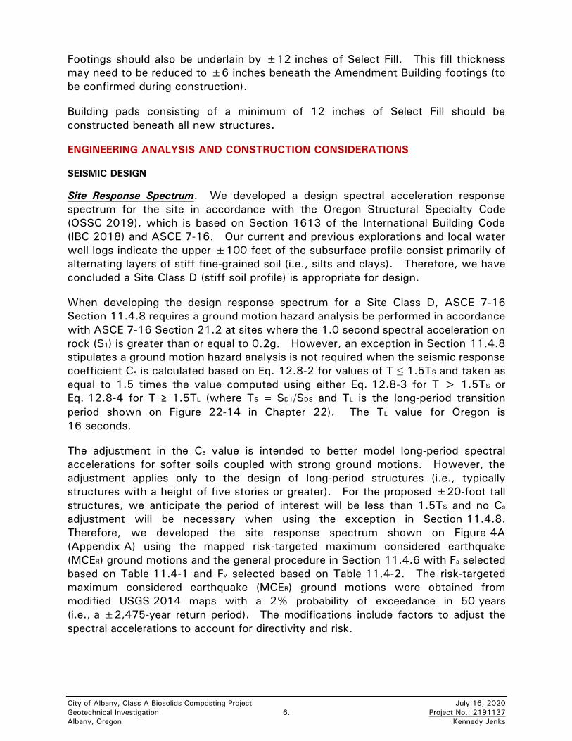
1. The Design Response Spectrum is based on OSSC 2019 Section 1613.2

which is based on ASCE 7-16 Section 11.4.

2. The following parameters are based on the modified USGS 2014 maps provided

in OSSC 2019:

Site Class= D Damping = 5%

SS = 0.80 Fa = 1.18 SMS = 0.94 SDS = 0.63

S1 = 0.42 Fv = 1.58 SM1 = 0.66 SD1 = 0.44

3. SS and S1 values indicated in Note 2 are the mapped, risk-targeted maximum considered

earthquake spectral acclerations for 2% probability of exceedence in 50 years.

4. Fa and Fv were established based on OSSC 2019 Tables 1613.2.3(1) and 1613.2.3(2)

using the selected SS and S1 values. SDS and SD1 values include a 2/3 reduction on

SMS and SM1 as discussed in OSSC 2019 Section 1613.2.3.

5. Site location is: Latitude 44.6440, Longitude -123.0775.

Albany, Oregon

FIGURE 4A

City of Albany, Class A Biosolids Composting Project

OSSC 2019 SITE RESPONSE SPECTRUM

Project No. 2191137

0.00

0.10

0.20

0.30

0.40

0.50

0.60

0.70

0 0.5 1 1.5 2 2.5 3

Sp

ec

tral A

cc

ele

rati

on

, S

a(g

)

Period (seconds)

OSSC 2019Response Spectrum

Photo 1A. Typical Composting Building

CharlesW
Callout
Side walls and dividers will be concrete ecology blocks
CharlesW
Line
CharlesW
Callout
Backwall will be concrete
CharlesW
Callout
Concrete slab floor
CharlesW
Text Box
Compost Building will be similar to this building

100’ x 208’ 

Photo 2A. Typical Amendment Building

CharlesW
Callout
Columns with spread footings
CharlesW
Callout
Instead of precast panels shown - we will use concrete ecology blocks to create divider walls inside the building.
CharlesW
Callout
Floor is AC paving
CharlesW
Text Box
Amendment Building will be similar to this example

Foundation Engineering, Inc.

City of Albany, Class A Biosolids Composting Project

Project No.: 2191137

Photo 3A. Near TP-2 looking east.

Photo 4A. Looking west from soil stockpile.

Appendix B

Test Pit Logs

Professional Geotechnical Services

Foundation Engineering, Inc.

DISTINCTION BETWEEN FIELD LOGS AND FINAL LOGS A field log is prepared for each boring or test pit by our field representative. The log contains information concerning sampling depths and the presence of various materials such as grovel, cobbles, and fill, and observations of ground water.

It also contains our interpretation of the soil conditions between samples. The final logs presented in this report represent our interpretation of the contents of the field logs and the results of the sample examinations and laboratory test results.

Our recommendations ore based on the contents of the final logs and the information contained therein and not on the

field logs.

VARIATION IN SOILS BETWEEN TEST PITS AND BORINGS The final log and related information depict subsurface conditions only at the specific location and on the dote indicated.

Those using the information contained herein should be aware that soil conditions at other locations or on other dotes may differ. Actual foundation or subgrode conditions should be confirmed by us during construction.

TRANSITION BETWEEN SOIL OR ROCK TYPES The lines designating the interface between soil, fill or rock on the final logs and on subsurface profiles presented in the report ore determined by interpolation and ore therefore approximate. The transition between the materials may be

abrupt or gradual. Only at boring or test pit locations should profiles be considered as reasonably accurate and then

only to the degree implied by the notes thereon.

SAMPLE OR TEST SYMBOLS SH-3-4 t t Lsample Number ~Boring or Test Pit Number

Sample Type

Top of Sample Attempt

Recovered Portion

Unrecovered Portion

Bottom of Sample Attempt

S - Grob Sample SS - Standard Penetration Test Sample (split-spoon) SH - Thin-walled Shelby Tube Sample

C - Pavement Core Sample CS - Rock Core Sample

A Standard Penetration Test Resistance equals the number of blows a 140 lb. weight falling 30 in. is required to drive a standard split-spoon sampler 1 ft. Practical refusal is equal to 50 or more blows per 6 in. of sampler penetration.

• Water Content (%).

UNIFIED SOIL CLASSIFICATION SYMBOLS FIELD SHEAR STRENGTH TEST G - Grovel S - Sand M - Silt C - Cloy Pt - Peat

W - Well Graded P - Poorly Graded L - Low Plasticity H - High Plasticity 0 - Organic

TYPICAL SOIL/ROCK SYMBOLS

~Concrete

~Organics

~Cloy

~ Sand -

~Grovel ~ [II] Silt

"11111 111111. FOUNDATION ENGINEERING INC. • llll1Jlli PROFESSIONAL GEOTECHNICAL SERVICES

820 ll1r Cormll AWD118 7811? ff CIRRlJS DRIVE, BUILDIRG 24

Conalllo, OR 97880 111.lVBR'IOH, OR 8?008 BUB. (1541) ?li?-'11146 BUB. (llOS) 841-11141

Iii! Basalt

lJ Sandstone

IHI Siltstone

Shear strength measurements on test pit side walls, blocks of soil or Shelby tube samples ore typically mode with Torvone or Field Vane shear devices.

WATER TABLE

I Water Tobie Location

(1/31/16) Dote of Measurement

SYMBOL KEY

BORING AND TEST PIT LOGS

Explanation of Common Terms Used in Soil Descriptions

Field Identification Cohesive Soils

SPT* Su~~ (tsf) Easily penetrated several inches 0 - 2 < 0.125 by fist. Easily penetrated several inches 2 4 0.125-0.25 by thumb. -

Can be ~enetrated several inches by thum with moderate effort. 4 - 8 0.25 - 0.50

Readily indented by thumb but 8 - 15 0.50 - 1.0 penetrated only with great effort.

Readily indented by thumbnail. 15 - 30 1.0 - 2.0 Indented with difficulty by thumbnail. >30 > 2.0

* SPT N-value in blows per foot (bpf) ** Undrained shear strength

Term Soil Dry Absence of moisture. Dusty.

Moisture Field Dry to the touch.

Term

Very Soft

Soft

Medium Stiff

Stiff

Very Stiff

Hard

Description

Granular SPT*

0 - 4

4 - 10

10 - 30

30 - 50

> 50

Damp Soil has moisture. Cohesive soils are below plastic limit and usually moldable.

Soils Term

Very Loose

Loose

Medium Dense

Dense

Very Dense

Moist Grains appear darkened, but no visible water. Silt/clay will clump. Sand will bulk. Soils are often at or near plastic limit.

Wet Visible water on larger grain surfaces. Sand and cohesionless silt exhibit dilatancy. Cohesive soil can be readily remolded. Soil leaves wetness on the hand when squeezed. Soil is wetter than the optimum moisture content and above the plastic limit.

Term Pl Plasticity Field Test Non-plastic 0 - 3 Cannot be rolled into a thread at any moisture.

Low Plasticity 3 - 15 Can be rolled into a thread with some difficulty.

Medium Plasticity 15 - 30 Easily rolled into thread.

High Plasticity > 30 Easily rolled and re-rolled into thread.

Term Soil Structure Criteria

Stratified Alternating layers at least 14 inch thick.

Laminated Alternating layers less than 14 inch thick.

Fissured Contains shears and partings along planes of weakness.

Slickensided Partings appear glossy or striated.

Blocky Breaks into small lumps that resist further breakdown.

Lensed Contains pockets of different soils.

,111111 11111" FOUNDATION ENGINEERING INC. ill1llill llllllJh PROFESSIONAL GEOTECHNICAL SERVICES

ll20 ff Cornell A,,...... 78117 S1f ClllRlJB DlllV& llUILDD1G 24

Cor9alllm, OB ll7ll30 llBAYBR'l'Olf, OB 8'1008 BOB. (1141) 7117-78411 BOB. (liOll) 841-11141

Term Soil Cementation Criteria

Weak Breaks under pressure.

light finger

Moderate Breaks under pressure.

hard finger

Strong Will not break with finger pressure.

COMMON TERMS

SOIL DESCRIPTIONS

No seepage or ground waterencountered to the limit of exploration.

Medium dense to dense silty sandy GRAVEL, scattered organics(GM); grey-brown, moist to wet, medium plasticity silt, fine tocoarse sand, fine to coarse subrounded to rounded gravel,organics consist of fine roots, (fill).Dense silty sandy GRAVEL, scattered organics (GM);grey-brown, moist, low plasticity silt, fine to coarse sand, fine tocoarse subrounded gravel, organics consist of wood, (fill).

BOTTOM OF EXPLORATION

S-1-1

S-1-2

196.51.5

192.06.0

196.51.5

192.06.0

Albany, Oregon

Surface Elevation:

Date of Test Pit:

Project No.:

Ele

v.

De

pth

Sy

mb

ol

198.0 feet (Approx.)

January 8, 2020

2191137 Test Pit Log: TP-1

Comments

De

pth

, F

ee

t

Sa

mp

le #

Lo

ca

tio

n

Soil and Rock Description

1

2

3

4

5

6

7

8

9

10

11

12C

, T

SF

City of Albany,

Albany Class A Biosolids Composting Project

Abundant roots at ±16 inches.

No seepage or ground waterencountered to the limit of exploration.

Medium dense to dense silty sandy GRAVEL, scattered debris(GM); grey-brown, moist, medium plasticity silt, fine to coarsesand, fine to coarse subrounded to rounded gravel, debrisconsists of plastic pipe and AC fragments, (fill).Dense silty sandy GRAVEL (GM); grey-brown, moist, mediumplasticity silt, fine to coarse sand, fine to coarse subrounded torounded gravel, (possible fill/alluvium).

Scattered cobbles up to ±6-inch diameter below ±5 feet.

Medium dense clayey sandy GRAVEL, some cobbles (GC);grey-brown, wet, medium plasticity clay, fine to coarse sand, fineto coarse angular gravel, subrounded to rounded cobbles to±10-inch diameter, (possible fill/alluvium).

Dense below ±10 feet.

BOTTOM OF EXPLORATION

S-2-1

S-2-2

S-2-3

199.81.2

195.06.0

190.011.0

199.81.2

195.06.0

190.011.0

Albany, Oregon

Surface Elevation:

Date of Test Pit:

Project No.:

Ele

v.

De

pth

Sy

mb

ol

201.0 feet (Approx.)

January 8, 2020

2191137 Test Pit Log: TP-2

Comments

De

pth

, F

ee

t

Sa

mp

le #

Lo

ca

tio

n

Soil and Rock Description

1

2

3

4

5

6

7

8

9

10

11

12

C,

TS

F

City of Albany,

Albany Class A Biosolids Composting Project

Gravelly sand lens from ±22 to 24inches.

No seepage or ground waterencountered to the limit of exploration.

Dense to very dense silty sandy GRAVEL (GM); grey-brown,moist, low to medium plasticity silt, fine to coarse sand, fine tocoarse subrounded to rounded gravel, (fill).

Dense to very dense clayey sandy GRAVEL, some cobbles(GC); grey-brown, moist, medium to high plasticity clay, fine tocoarse sand, fine to coarse subangular gravel, cobbles to 6-inchdiameter, (fill).Medium dense silty sandy GRAVEL (GM); grey, wet, mediumplasticity silt, fine to coarse sand, fine to coarse subrounded tosubangular gravel, (fill).BOTTOM OF EXPLORATION

S-3-1

S-3-2

S-3-3

196.03.0

194.54.5

192.56.5

196.03.0

194.54.5

192.56.5

Albany, Oregon

Surface Elevation:

Date of Test Pit:

Project No.:

Ele

v.

De

pth

Sy

mb

ol

199.0 feet (Approx.)

January 8, 2020

2191137 Test Pit Log: TP-3

Comments

De

pth

, F

ee

t

Sa

mp

le #

Lo

ca

tio

n

Soil and Rock Description

1

2

3

4

5

6

7

8

9

10

11

12C

, T

SF

City of Albany,

Albany Class A Biosolids Composting Project

Surface: grass

No seepage or ground waterencountered to the limit of exploration.

Very dense silty sandy GRAVEL (GM); grey-brown, damp tomoist, low plasticity silt, fine to coarse sand, fine to coarsesubrounded to rounded gravel, (fill).

Dense clayey sandy GRAVEL, scattered cobbles and debris(GC); grey, moist, medium to high plasticity clay, fine to coarsesand, fine to coarse subrounded to rounded gravel, cobbles up to±5-inch diameter, debris consists of plastic fragments, (fill).Stiff to very stiff CLAY, scattered organics and debris (CH);brown, moist, high plasticity, organics consist of grass, debrisconsists of paper, metal, and other rubbish, (fill).

Medium stiff and wet below ±6 feet.BOTTOM OF EXPLORATION

S-4-1

S-4-2

199.52.5

197.54.5

195.56.5

199.52.5

197.54.5

195.56.5

Albany, Oregon

Surface Elevation:

Date of Test Pit:

Project No.:

Ele

v.

De

pth

Sy

mb

ol

202.0 feet (Approx.)

January 8, 2020

2191137 Test Pit Log: TP-4

Comments

De

pth

, F

ee

t

Sa

mp

le #

Lo

ca

tio

n

Soil and Rock Description

1

2

3

4

5

6

7

8

9

10

11

12

C,

TS

F

City of Albany,

Albany Class A Biosolids Composting Project

No seepage or ground waterencountered to the limit of exploration.

Test pit terminated due to encounteringpossible utility trench backfill.

Dense silty sandy GRAVEL, some cobbles, scattered debris(GM); grey-brown, moist, low plasticity silt, fine to coarse sand,fine to coarse subrounded gravel, cobbles up to ±5-inchdiameter, (fill).

Very dense CRUSHED GRAVEL (GP); grey-brown, moist,¾-inch minus angular gravel, (fill).BOTTOM OF EXPLORATION

S-5-1

198.04.0

197.54.5

198.04.0

197.54.5

Albany, Oregon

Surface Elevation:

Date of Test Pit:

Project No.:

Ele

v.

De

pth

Sy

mb

ol

202.0 feet (Approx.)

January 8, 2020

2191137 Test Pit Log: TP-5

Comments

De

pth

, F

ee

t

Sa

mp

le #

Lo

ca

tio

n

Soil and Rock Description

1

2

3

4

5

6

7

8

9

10

11

12C

, T

SF

City of Albany,

Albany Class A Biosolids Composting Project

Surface: grass

No seepage or ground waterencountered to the limit of exploration.

Stiff silty CLAY, scattered organics (CH); brown and iron-stained,moist, medium to high plasticity, organics consist of fine roots,(fill).

Medium dense to dense silty sandy GRAVEL (GM); grey-brown,moist, low to medium plasticity silt, fine to coarse sand, fine tocoarse subrounded gravel, (fill).BOTTOM OF EXPLORATION

S-6-1202.0

4.0

200.55.5

202.04.0

200.55.5

Albany, Oregon

Surface Elevation:

Date of Test Pit:

Project No.:

Ele

v.

De

pth

Sy

mb

ol

206.0 feet (Approx.)

January 8, 2020

2191137 Test Pit Log: TP-6

Comments

De

pth

, F

ee

t

Sa

mp

le #

Lo

ca

tio

n

Soil and Rock Description

1

2

3

4

5

6

7

8

9

10

11

12

C,

TS

F

City of Albany,

Albany Class A Biosolids Composting Project


Recommended