Page 1
Integrated Project
ABSOLUTE - Aerial Base Stations with Opportunistic Links for
Unexpected & Temporary Events
Contract No.318632
Deliverable
FP7-ICT-2011-8-318632-ABSOLUTE/D5.7
Qualification and Certification Framework Report
Contractual date: 26/03/2015
Actual date: 31/03/2015
Authors/Editors: Romain Hermenier, Macià Mut, Vincent Boussemart (TGS)
Philippe Charpentier (TCS)
Sandy Allsopp (HLK)
Participants: TGS, TCS, HLK
Work package: WP5 – T5.7
Security: PU
Nature: Report
Version: V1.0
Total number of pages: 33
Abstract
This deliverable aims at providing a first insight into the qualification and certification framework
within the ABSOLUTE project. First this report will present the qualification and certification
procedures of the aerial platform used for the final demonstration. Then, although it is not foreseen to
have qualified and certified avionics components for the proof-of-concept, this deliverable will touch
upon the certification procedures within Europe that could be relevant for a future exploitation of the
ABSOLUTE system. Finally a section highlighting some guidance for public and worker protection
against antenna radiation will close the document.
Keywords
Qualification, certification, aerial platform, launch system, EASA, airworthiness, UAV, ETSO
certification, guidance, antenna radiation, worker protection, satellite, terrestrial
Ref. Ares(2015)1739245 - 24/04/2015
Page 2
ABSOLUTE D5.7
Dissemination Level PU Page 2
Table of Contents
List of Figures ......................................................................................................................................... 3
List of Tables ........................................................................................................................................... 4
Abbreviations .......................................................................................................................................... 5
Executive Summary ................................................................................................................................ 6
1 Introduction .......................................................................................................................................... 7
2 Qualification and Certification for Aerial Platform ............................................................................. 8
2.1 Qualification .................................................................................................................................. 8
2.1.1 Will the Helikite: ........................................................................................................................ 8
2.1.2 Will the launch system: .............................................................................................................. 9
2.2 Certification ................................................................................................................................. 10
2.2.1 Helikite ..................................................................................................................................... 10
2.2.2 Launch System: ........................................................................................................................ 11
3 Aerial and Avionics Components Certifications ................................................................................ 13
3.1 Introduction ................................................................................................................................. 13
3.2 Initiation towards the EASA airworthiness certification procedure ............................................ 13
3.3 The Unmanned Aircraft Systems (UAV) case ............................................................................ 14
3.4 Equipment approval : EASA ETSO certification ........................................................................ 15
4 Guidance for Public/Worker Protection against antenna radiation .................................................... 17
4.1 Introduction ................................................................................................................................. 17
4.2 Ka-band dish antenna .................................................................................................................. 19
4.3 Helix antenna ............................................................................................................................... 21
4.4 Dipole antenna array ................................................................................................................... 22
5 Conclusion .......................................................................................................................................... 23
Appendix – 1 ......................................................................................................................................... 24
Appendix – 2 ......................................................................................................................................... 25
References ............................................................................................................................................. 33
Acknowledgement ................................................................................................................................. 33
Page 3
ABSOLUTE D5.7
Dissemination Level PU Page 3
List of Figures
Figure 1: Example of an ADOA to achieve an EASA ETSO authorization ......................................... 16
Figure 2: Exposure Limits for worker and general public ..................................................................... 18
Figure 3: Deployable Ka-band satellite terminal ................................................................................... 19
Figure 4: Safety computed zone for the satellite Ka-band terminal ...................................................... 20
Figure 5: Antenna installation recommendations on LAP .................................................................... 21
Figure 6: Safety computed zone for the LAP antenna ........................................................................... 21
Figure 7: Antenna installation recommendations on a tripod ................................................................ 22
Figure 8: Safety computed zone for the tripod antenna ......................................................................... 22
Page 4
ABSOLUTE D5.7
Dissemination Level PU Page 4
List of Tables
Table 1: Exposure Limits for worker and general public ...................................................................... 17
Table 2: Ka band antenna characteristics .............................................................................................. 19
Table 3: Calculated limits for the satellite dish in distances and energy fields for general public and
workers ......................................................................................................................................... 19
Table 4: Calculated limits for the LAP antenna in distances and energy fields for general public and
workers ......................................................................................................................................... 21
Table 5: Calculated limits for the tripod antenna in distances and energy fields for general public and
workers ......................................................................................................................................... 22
Page 5
ABSOLUTE D5.7
Dissemination Level PU Page 5
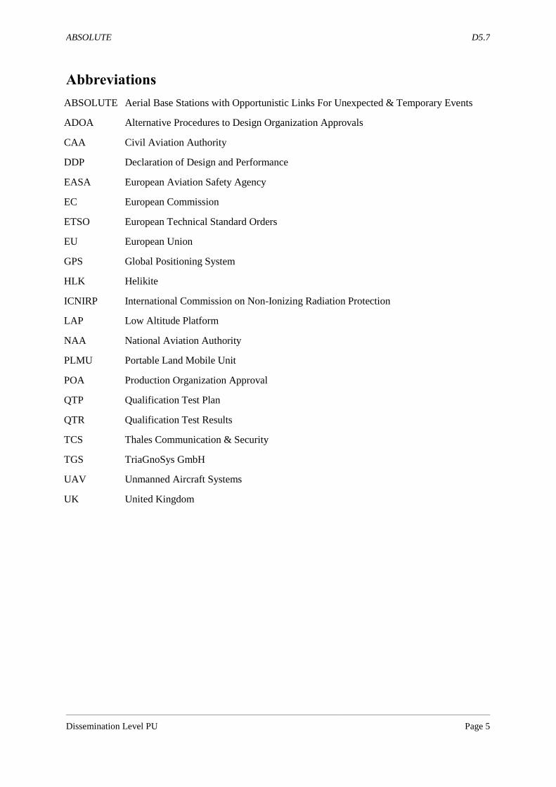
Abbreviations
ABSOLUTE Aerial Base Stations with Opportunistic Links For Unexpected & Temporary Events
ADOA
CAA
Alternative Procedures to Design Organization Approvals
Civil Aviation Authority
DDP Declaration of Design and Performance
EASA
EC
European Aviation Safety Agency
European Commission
ETSO
EU
GPS
HLK
ICNIRP
LAP
European Technical Standard Orders
European Union
Global Positioning System
Helikite
International Commission on Non-Ionizing Radiation Protection
Low Altitude Platform
NAA National Aviation Authority
PLMU
POA
Portable Land Mobile Unit
Production Organization Approval
QTP
QTR
TCS
Qualification Test Plan
Qualification Test Results
Thales Communication & Security
TGS TriaGnoSys GmbH
UAV
UK
Unmanned Aircraft Systems
United Kingdom
Page 6
ABSOLUTE D5.7
Dissemination Level PU Page 6
Executive Summary
This deliverable corresponds to deliverable D5.7 “Qualification and Certification framework Report”,
due Month 30. The objective of this deliverable is to provide a first overview report of the expected
regulatory, qualification and certification framework for a future implementation of the ABSOLUTE
system. Although it is not foreseen to have qualified and certified avionics components for the proof-
of-concept, it is of paramount importance for a later exploitation of the ABSOLUTE concept to know
what the regulations in effect are in terms of airworthiness.
To this end, Chapter 2 first presents the qualification and certification procedures applying to the aerial
platform to be used for the final demonstration. It does not only focus on the flying platform itself, but
also includes the regulatory processes applying to the launch system of the aerial platform. Some
regulatory aspects about the system deployment, the material used and the electronic devices on board
are also discussed.
Chapter 3 then concentrates on providing a brief introduction into the world of airworthiness
qualification and certification within Europe by presenting the certification procedures that could be
relevant for a future exploitation of the ABSOLUTE proof-of-concept. The overall EASA
airworthiness regulatory process is touched upon as well as the current procedures towards Unmanned
Aircraft Systems (UAV). A last subsection about how the equipment manufacturer can obtain an
ETSO authorization when aeronautical equipment is not certified as part of the product closes this
chapter.
Finally Chapter 4 exposes some guidance related to public and worker protection against antenna
radiation. Based on some recommendations and directives provided by the European Commission, it
gives the reader some insights on how to compute the minimum distance required between
workers/public and a working antenna to avoid strong radiations. This analysis considers all the
antenna types used in the ABSOLUTE project, namely a satellite Ka-Band dish antenna, an Helix
antenna and an dipole antenna array.
Chapter 5 concludes the document.
Page 7
ABSOLUTE D5.7
Dissemination Level PU Page 7
1 Introduction
The use of flying platform containing electronic equipments within the ABSOLUTE project addresses
the issues of understanding on the one hand the regulatory procedures of flying objects and on the
other hand the qualification and certification processes to be applied to the avionics equipment. While
the project’s design and development work does not have the ambition to come up with qualified and
certified avionics components for the proof-of-concept, it is still meaningful to understand and be
aware of all related implications and requirements of any applicable processes and standards for a later
exploitation.
As an already certified product, the Helikite aerial platform used for the ABSOLUTE demonstration
already fulfils the safety and regulatory requirements. The later encompass procedures for the platform
itself (such as materials used, visible safety features, deployment phase...) but also for the personal
using the platform. It is also worth mentioning that some requirements are also necessary for the
launch system of the platform.
As to the avionic equipment, the European Aviation Safety Agency (EASA [1]) requires the product
manufacturer to obtain the appropriate European Technical Standard Orders (ETSO) authorization in
order for this equipment to be certified as part of the overall product. It is therefore of interest for a
later implementation of the ABSOLUTE system to understand how an ETSO authorization works and
what the requested document for such authorization are.
Furthermore, deploying a system such as ABSOLUTE could easily raise the issue of the worker safety
towards antenna radiation. Indeed the ABSOLUTE system use a bunch of satellite and terrestrial
antennas with different antenna patterns and transmitting power. Here again, understanding the
European regulations about antenna exposure limits is of paramount importance for the public and
worker safety.
The deliverable is thus structured as follows. Chapter 2 will present and highlight the existing
qualification and certification procedures of the aerial platform as well as its launch system. The main
airworthiness certification processes will then be discussed in Chapter 3, with a focus on the UAV
case and the ETSO authorization. Some guidance for public and worker protection against antenna
radiation is described in Chapter 4. Finally Chapter 5 concludes the document.
Page 8
ABSOLUTE D5.7
Dissemination Level PU Page 8
2 Qualification and Certification for Aerial Platform
For sake of clarity towards the qualification and certification procedures of the aerial platform and its
dedicated launch system used in ABSOLUTE, this section has been written using a “question/answer”
approach.
2.1 Qualification
2.1.1 Will the Helikite:
1) Fly steadily in the proscribed weather conditions for long enough?
The 34m3 Desert Star Helikite has been extensively tested in winds between 0 and 50mph, which are
the wind speeds required by the ABSOLUTE project. The Helikite flew well in these winds for long
periods. It also flew in rain, snow and high temperatures with no problems.
2) Have enough lifting capability to lift the payload to the proscribed altitude correctly in all
these conditions?
The ABSOLUTE payload is expected to be 10Kg or less. The 34m3 Desert Star Helikite has a pure
helium lift of 14Kg in no wind which is enough to lift the payload plus flying line up to the proscribed
1,000ft altitude for the trials. In a 15 mph wind it was tested to lift 30Kg. In higher winds it lifts even
more. If it happens that the payload ends up being a heavier weight than 10Kg, then a larger 40m3
Desert Star Helikite can be supplied instead that uses the same ground handling equipment as the
34m3.
3) Will the electronics function correctly while on the Helikite?
This is only possible to test when the electronics are finished, which has not happened yet.
4) Accommodate the radio/electronics + Antennas + Batteries + Fibre-Optic in the correct way?
Representative models plus actual batteries of the electrical components have been fitted to the
Helikite with no problems. However, until the electronics are finished it is not possible to fit them.
5) Be easy and quick to operate?
For the ABSOLUTE project, the Helikite requires to be operated with a minimum of two people in all
designated weather conditions, night and day. This has been extensively tested over many months in
different weather conditions night and day, both from the dedicated Helikite Trailer and the ground-
based launch Helibase system. The deployment has always been trouble-free and in fact perfectly
possible for only one person even in high winds.
6) Be transported easily enough?
The Ground-Based Helikite Launch System can be packed up into a number of Pelicases and hold-alls.
These can quickly be placed in the back of a van or pick-up truck and driven wherever required. The
helium cylinders can be secured to the pick-up truck or van internal structural wall for safe transport.
This was successfully tested.
The dedicated ABSOLUTE Helikite Trailer combines the functions of helium cylinder handling,
helium transport, Helikite transport and Helikite launch - all into one unit. This has been extensively
tested both on and off road, and has been in almost constant use launching Helikites for many months.
It has performed flawlessly.
7) Be stored well enough for long periods?
There are two types of storage:
a) Long-term storage in the depot of the Helikite system ready for deployment.
Page 9
ABSOLUTE D5.7
Dissemination Level PU Page 9
This has been tested since the beginning of the ABSOLUTE project two years ago. The Helikite
polyurethane balloon materials, which are the most likely to deteriorate in long-term storage, have
been kept in cool, dry, dark conditions as proscribed. The materials have shown no sign of
deterioration. Allsopp Helikites Ltd has in fact kept similar materials for 20 years in such conditions
with very little deterioration. However, it is recommended that the Helikite balloons are replaced every
4 years as a routine precaution.
The other possible storage problem will be the helium in the cylinders, as it is possible it might leak
out over many years. This possibility can be eliminated by testing the cylinders every 3 months when
in storage. By law, the helium cylinders need to be strength-tested by their manufacturers every 4
years.
b) Inflated storage on the Helibase or the Trailer during times when the Helikite has been
deployed but is not required to be flying for some reason.
It is essential that an inflated Helikite has somewhere safe to rest in all weather conditions when not in
flight. The most common form of damage to aerostats is due to incorrect ground storage.
The ABSOLUTE Helikite was tested for inflated storage both on the ground-based, air-inflated
Helibase and on the Helikite Trailer over many months outside in all weathers, winter and summer.
Both systems performed very well. Even in the severest gales there was no damage to the Helikite.
The balloon materials did not rot or wear due to damp or long-term vibration. Polyurethane balloon
material can quickly rot if left in damp, warm conditions is an enclosed place such as when placed wet
into a sealed storage box. However, the polyurethane balloons do not seem to rot if they are kept
inflated outside. This is probably due to the good air circulation that kills any offending fungus.
2.1.2 Will the launch system:
1) Be easy to transport to site?
The ground based Helikite launch system fits easily into a van or pick-up truck. These were tested and
proved to be suitable to be driven on or off-road to any suitable site.
The Helikite trailer was tested on and off road and is capable of being trailed to the centre of a field or
anywhere in urban areas for rapid launch. The trailer is more versatile than the ground launch system,
because setting up on areas of concrete such as car-parks is straightforward.
2) Fast enough to set up in time? During tests at Allsopp Helikites flying facility, set-up time for the ground launched system was under
one hour, and for the trailer it was under 30 minutes. Both these times are within the ABSOLUTE
criterior.
3) Launch the Helikite correctly and safely?
During tests at Allsopp Helikites flying facility, launching took place numerous times from both the
ground-based system and the trailer. At all times launch occurred correctly and safely with no
particular problems.
4) Transport the helium safely?
The transport of helium in the pick-up truck can be done by fastening the helium to be firmly to the
floor of the truck using the strong tie-down points provided. Helium can also be attached vertically to
the bars at the front of the flatbed.
In the van the cylinders were at times secured either vertically or horizontally using suitable strong-
points. Either method was fine. It is important to ensure that there is a bulkhead between the driver and
the helium cylinders so that if gas escapes it cannot reach the driver.
Page 10
ABSOLUTE D5.7
Dissemination Level PU Page 10
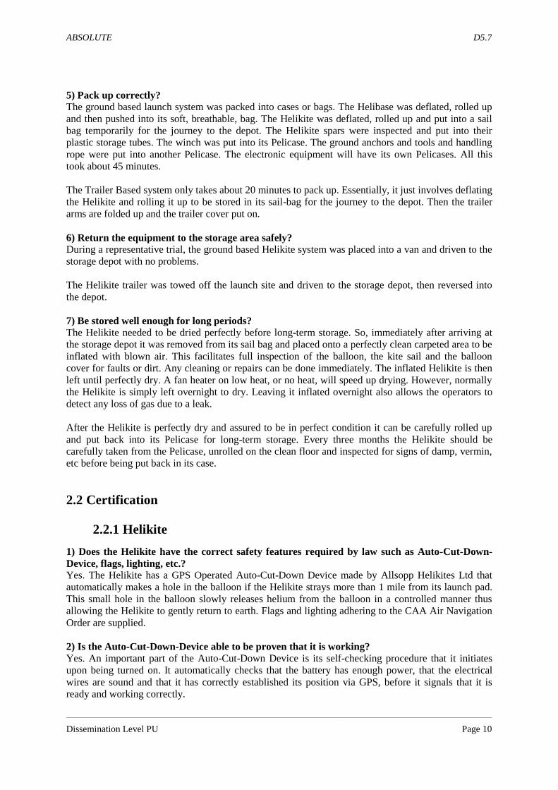
5) Pack up correctly?
The ground based launch system was packed into cases or bags. The Helibase was deflated, rolled up
and then pushed into its soft, breathable, bag. The Helikite was deflated, rolled up and put into a sail
bag temporarily for the journey to the depot. The Helikite spars were inspected and put into their
plastic storage tubes. The winch was put into its Pelicase. The ground anchors and tools and handling
rope were put into another Pelicase. The electronic equipment will have its own Pelicases. All this
took about 45 minutes.
The Trailer Based system only takes about 20 minutes to pack up. Essentially, it just involves deflating
the Helikite and rolling it up to be stored in its sail-bag for the journey to the depot. Then the trailer
arms are folded up and the trailer cover put on.
6) Return the equipment to the storage area safely?
During a representative trial, the ground based Helikite system was placed into a van and driven to the
storage depot with no problems.
The Helikite trailer was towed off the launch site and driven to the storage depot, then reversed into
the depot.
7) Be stored well enough for long periods?
The Helikite needed to be dried perfectly before long-term storage. So, immediately after arriving at
the storage depot it was removed from its sail bag and placed onto a perfectly clean carpeted area to be
inflated with blown air. This facilitates full inspection of the balloon, the kite sail and the balloon
cover for faults or dirt. Any cleaning or repairs can be done immediately. The inflated Helikite is then
left until perfectly dry. A fan heater on low heat, or no heat, will speed up drying. However, normally
the Helikite is simply left overnight to dry. Leaving it inflated overnight also allows the operators to
detect any loss of gas due to a leak.
After the Helikite is perfectly dry and assured to be in perfect condition it can be carefully rolled up
and put back into its Pelicase for long-term storage. Every three months the Helikite should be
carefully taken from the Pelicase, unrolled on the clean floor and inspected for signs of damp, vermin,
etc before being put back in its case.
2.2 Certification
2.2.1 Helikite
1) Does the Helikite have the correct safety features required by law such as Auto-Cut-Down-
Device, flags, lighting, etc.?
Yes. The Helikite has a GPS Operated Auto-Cut-Down Device made by Allsopp Helikites Ltd that
automatically makes a hole in the balloon if the Helikite strays more than 1 mile from its launch pad.
This small hole in the balloon slowly releases helium from the balloon in a controlled manner thus
allowing the Helikite to gently return to earth. Flags and lighting adhering to the CAA Air Navigation
Order are supplied.
2) Is the Auto-Cut-Down-Device able to be proven that it is working?
Yes. An important part of the Auto-Cut-Down Device is its self-checking procedure that it initiates
upon being turned on. It automatically checks that the battery has enough power, that the electrical
wires are sound and that it has correctly established its position via GPS, before it signals that it is
ready and working correctly.
Page 11
ABSOLUTE D5.7
Dissemination Level PU Page 11
3) Are the materials of the Helikite suitable for purpose?
Yes. The kite part of the Helikite is made from rip-stop nylon resistant to UV and and a well known
kite and sail making material. The balloon is pure polyurethane which is the best quality balloon
material available. The balloon does not endure structural stresses as it is contained within the outer
balloon cover. This outer cover is made from Allsopp Helikites` 'Ultra' material which is a lightweight
composite of woven polyethylene and polyester that is UV resistant and very strong.
4) Are the materials strong enough for purpose? What is their strength?
The materials have been proven over many years of Helikite flying hours to be exceptionally strong
and suitable for all normal conditions. See also in Appendix – 1, the table of Helikite Material
Strengths.
5) Are there safety lines to the payload components?
Yes. These go from the payload component to the main body of the Helikite.
6) Has a Health and Safety Assessment been completed for the Helikite structure and handling?
Yes. Please refer to appendix – 2.
2.2.2 Launch System:
1) Are the ground anchorage points strong enough and strength rated?
The 'Grabba' ground anchor has a structural steel ring rated to 1,500Kg which give it a 3X safety
margin for strength.
2) Is the Helikite allowed to operate from the launch site?
The vast majority of places in Europe are legal for Helikites to operate from without a licence or even
air-traffic permission up to certain altitudes. Above 200ft permission may be needed in some areas
such as the UK. Above 400ft air-traffic permission is always needed almost everywhere, but this is
generally easy enough to obtain quite quickly. The only places generally prohibited without air-traffic
control permission are the air-traffic-zones of registered airfields and emergency helicopter landing
pads. It is important to investigate the legal requirements of each site regarding Helikite flight.
3) Is the tether line strong enough with adequate margin of safety?
The flying line is 1,900 Kg breaking strain Dyna 1 Dyneema. As the expected line load is expected to
be no more than 500Kg in the 50mph top recommended wind speed, there is a 3.8X safety margin.
4) Has a Health and Safety Assessment been completed for the launch and operation of the
Helikite?
Yes. Please refer to appendix – 2.
5) Are the personnel involved proven to be adequately trained in Helikite operations?
Yes. They have long experience in Helikite operations in multiple different countries and have a 100%
safety record.
6) Is the trailer of correct design and have the correct warning signs etc?
The trailer is designed with all the relevant health and safety features in mind. It has a massively
strong chassis construction of galvanised steel. It has twin axles but can function with only one axle if
required thus providing redundancy in case of a tyre puncturing. It is highly stable at the legal speed
limit on tarmac roads and it is also a capable off-road trailer with a high enough ground clearance. The
Page 12
ABSOLUTE D5.7
Dissemination Level PU Page 12
helium is stored in steel cylinders firmly strapped down to the trailer. The cylinders are protected from
knocks and there is a special ramp provided allowing the cylinders to be easily and safely pulled onto
the trailer. The Helikite is very easily and safely inflated and flown from the trailer in all weathers. The
trailer has the designated warning sign relating to the carriage of stored helium in pressurised
cylinders.
Page 13
ABSOLUTE D5.7
Dissemination Level PU Page 13
3 Aerial and Avionics Components Certifications
3.1 Introduction
This chapter aims at providing a brief introduction into the world of airworthiness qualification
and certification within Europe. Due to the complexity of this process, the following information just
touches upon the certification procedures that could be relevant for a future exploitation of the
ABSOLUTE proof-of-concept. The reader is invited to refer to the provided references for more
detailed insights on this topic.
3.2 Initiation towards the EASA airworthiness certification procedure
The European Aviation Safety Agency (EASA [1]) corresponds to the civil aviation authority in
Europe and is responsible for determining all aviation policy Europe-wide. Created by EC Regulation
1592/2002, the main goal of the agency is to establish and maintain a high uniform level of civil
aviation safety in Europe. To achieve it, basic regulations have been instituted and apply to the design,
production, maintenance and operation of aeronautical products, parts and appliances, as well as
personnel and organisations involved not only in the design, production and maintenance of such
products, parts and appliances but also in the operation of aircraft [2]. Each of these regulations
focuses on an aspect of civil aviation safety (such as initial airworthiness, continuing airworthiness, air
crew, air operations, etc...) and contains implementing rules to ensure that all products meet the level
of safety required by the basic regulation. Additionally EASA issues certification specifications, which
contains guidance material and acceptable means of compliance, to assist in the understanding and
also demonstrate compliance with the implementing rules.
Any aircraft which is subject to the EASA regulation and implementing rules will be required to
have an EASA airworthiness certificate. In order to obtain a standardised aeronautical product, a
specific procedure within EASA has to be followed [3]. The applicant must first submit a type
certificate whose eligibility will be assessed by EASA. If accepted, technical investigation will be
further processed by a team of experts either from EASA or from a National Aviation Authority
(NAA). Once a certification team established, the EASA type certification process can generally be
divided in four different phases1:
- Phase I – Technical Familiarization and establishment of the Type Certification Basis
Once a sufficient degree of maturity is considered reached, the aircraft manufacturer
presents the project to EASA. The objective of this phase is to provide technical information
about the project to the Team experts to enable the definition of and the agreement on the
initial EASA Type Certification Basis.
- Phase II – Agreement of the Certification Program
EASA and the manufacturer need to define and agree on the means to demonstrate
compliance of the aircraft type with each requirement of the Certification Basis.
1 This process is valid for EU products. For non EU products, please refer to [3] for the certification procedure
Page 14
ABSOLUTE D5.7
Dissemination Level PU Page 14
- Phase III – Compliance determinations
The objective of this phase is the demonstration of compliance with the Certification Basis
and the acceptance of the compliance demonstration.
- Phase IV- Final Report and issue of a Type Certificate
The objective of this phase is the establishment of a project final report recording details
of the type investigation and, based on approval of the final report by the responsible
certification manager, the issue of the EASA Type Certificate.
During the certification process, a co-ordination with a number of other activities is also required.
These activities include:
- Aircraft/Engine/Propeller interactions
The applicant is responsible for the installation of the engine/propeller within the aircraft
and has to show compliance with installation requirements that apply to over and above those
required for the separate type certification of the engine/propeller.
- Environmental protection
The applicant has to show compliance with the applicable aircraft noise and fuel venting
requirements as well as with the applicable engine emissions requirements.
- Maintenance and Operation interactions
- Design and Production Organization approval
- Equipment approval
For the approval of equipment to be certified as part of the Product, the applicant is
responsible for the approval of the equipment and its installation. An acceptable mean of
providing compliance data in support of the equipment and its installation is to show that the
equipment meets the appropriate European Technical Standard Orders (ETSO) standard.
- Continuing Airworthiness
- Approval of Flight Conditions
- Reporting System
3.3 The Unmanned Aircraft Systems (UAV) case
The basic regulations and its implementing rules do not apply to aircraft engaged in military,
customs, police or similar services (State aircraft), although EU Member States must, however, ensure
that such services fulfil similar requirements to the objectives of the EASA Regulation. Furthermore
some categories of civil aircraft are also not required to meet the EASA requirements:
- aircraft specifically designed or modified for research, experimental or scientific purposes and
likely to be produced in very limited numbers;
- aircraft whose initial design was intended for military purposes only;
- and unmanned aircraft with an operating mass of less than 150 kg.
Page 15
ABSOLUTE D5.7
Dissemination Level PU Page 15
It must be noted that aircrafts which are exempt of EASA regulation (such as an unmanned aircraft
less than 150 kg) remains anyway subject to national regulation about airworthiness certification and
continuing certification.
As to unmanned aircraft requiring an airworthiness certification (more than 150 kg), the applicant
must follow the procedure described in section 3.2 by submitting a type certificate and demonstrate
compliance with a defined type certification basis. Once the compliance with the approved type design
has been proved, a certificate of airworthiness is issued to an individual unmanned aircraft. More
insights on the certification procedure for unmanned aircraft can be found in [4] and [5].
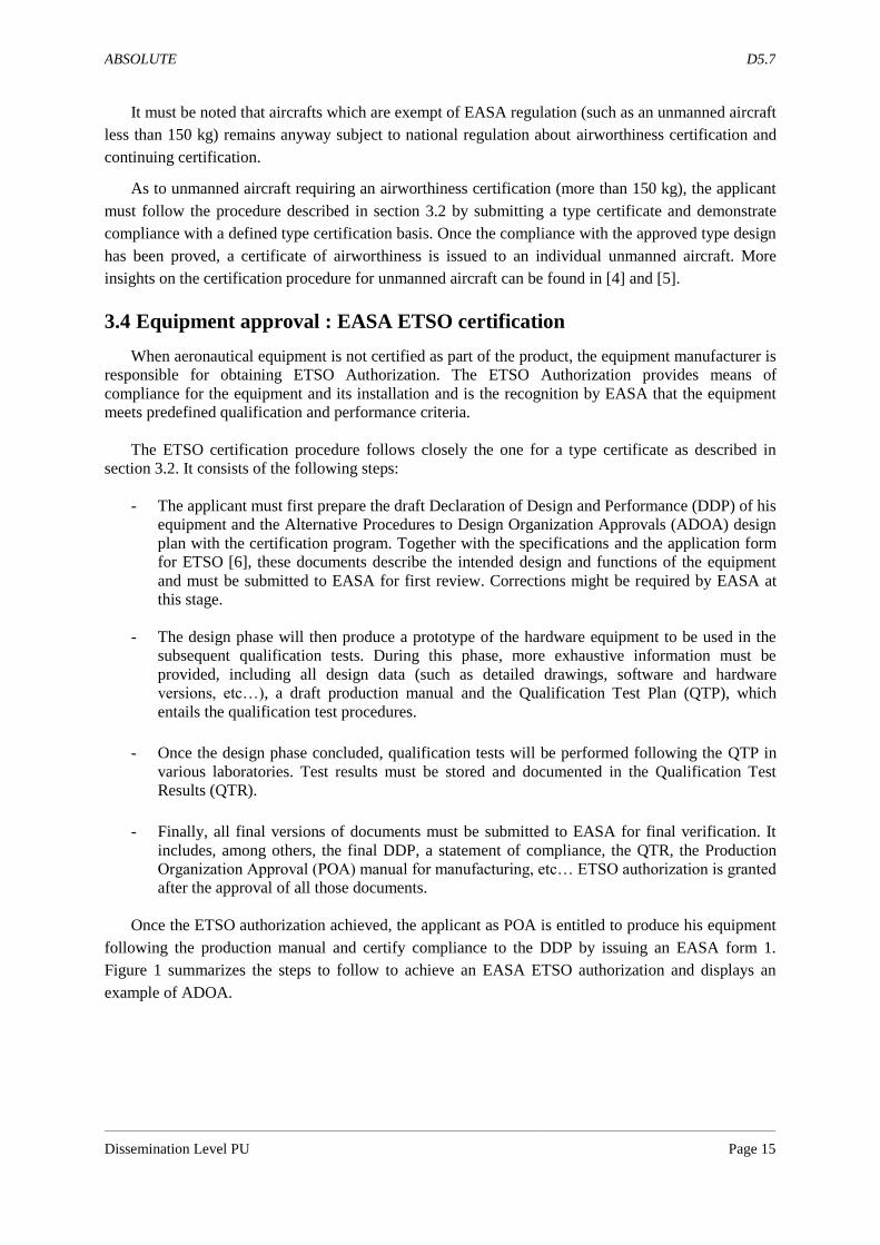
3.4 Equipment approval : EASA ETSO certification
When aeronautical equipment is not certified as part of the product, the equipment manufacturer is
responsible for obtaining ETSO Authorization. The ETSO Authorization provides means of
compliance for the equipment and its installation and is the recognition by EASA that the equipment
meets predefined qualification and performance criteria.
The ETSO certification procedure follows closely the one for a type certificate as described in
section 3.2. It consists of the following steps:
- The applicant must first prepare the draft Declaration of Design and Performance (DDP) of his
equipment and the Alternative Procedures to Design Organization Approvals (ADOA) design
plan with the certification program. Together with the specifications and the application form
for ETSO [6], these documents describe the intended design and functions of the equipment
and must be submitted to EASA for first review. Corrections might be required by EASA at
this stage.
- The design phase will then produce a prototype of the hardware equipment to be used in the
subsequent qualification tests. During this phase, more exhaustive information must be
provided, including all design data (such as detailed drawings, software and hardware
versions, etc…), a draft production manual and the Qualification Test Plan (QTP), which
entails the qualification test procedures.
- Once the design phase concluded, qualification tests will be performed following the QTP in
various laboratories. Test results must be stored and documented in the Qualification Test
Results (QTR).
- Finally, all final versions of documents must be submitted to EASA for final verification. It
includes, among others, the final DDP, a statement of compliance, the QTR, the Production
Organization Approval (POA) manual for manufacturing, etc… ETSO authorization is granted
after the approval of all those documents.
Once the ETSO authorization achieved, the applicant as POA is entitled to produce his equipment
following the production manual and certify compliance to the DDP by issuing an EASA form 1.
Figure 1 summarizes the steps to follow to achieve an EASA ETSO authorization and displays an
example of ADOA.
Page 16
ABSOLUTE D5.7
Dissemination Level PU Page 16
Figure 1: Example of an ADOA to achieve an EASA ETSO authorization
Page 17
ABSOLUTE D5.7
Dissemination Level PU Page 17
4 Guidance for Public/Worker Protection against antenna
radiation
4.1 Introduction
Exposure limits for electromagnetic fields was determined by the International Commission on Non-
Ionizing Radiation Protection (ICNIRP). Based on these values, the European Community drafts
recommendations and directives regarding the exposure of the public and of workers from the risks
arising from electromagnetic fields:
- Recommendation 1999/519/EC for the general public
- Directive 2004/40/EC for workers
These texts define limits on exposure which “are based directly on established health effects and
biological considerations. Compliance with these limits will ensure that people exposed to
electromagnetic fields are protected against all known adverse health effects”.
The main difference between workers and general public is that workers “who are exposed to risks
from electromagnetic fields at work and/or their representatives shall have received any necessary
information and training” relating to the outcome of the risk assessment provided, concerning in
particular “the values and concepts of the exposure limit values and the associated potential risks” and
“safe working practices to minimize risks from exposure”.
Exposure limit and action values for electric fields are exposed in tables below and represented on
below curves.
Frequency range Exposure limit for worker regarding
electric field strength, E (V/m)
0 - 25 Hz 20000
0,025 - 0,82 kHz 500/f
0,82 - 1000 kHz 610
1 - 10 MHz 610/f
10 - 400 MHz 61
400 - 2000 MHz 3f^1/2
2 - 300 GHz 137
Frequency range Exposure limit of the general public regarding
electric field strength, E (V/m)
0 - 25 Hz 10000
0,025 - 3 kHz 250/f
3 - 1000 kHz 87
1 - 10 MHz 87/(f^1/2)
10 - 400 MHz 28
400 - 2000 MHz 1,375f^1/2
2 - 300 GHz 61
Table 1: Exposure Limits for worker and general public
Page 18
ABSOLUTE D5.7
Dissemination Level PU Page 18
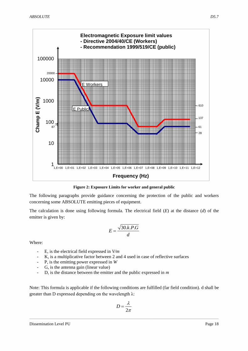
Figure 2: Exposure Limits for worker and general public
The following paragraphs provide guidance concerning the protection of the public and workers
concerning some ABSOLUTE emitting pieces of equipment.
The calculation is done using following formula. The electrical field (E) at the distance (d) of the
emitter is given by:
Where:
- E, is the electrical field expressed in V/m
- K, is a multiplicative factor between 2 and 4 used in case of reflective surfaces
- P, is the emitting power expressed in W
- G, is the antenna gain (linear value)
- D, is the distance between the emitter and the public expressed in m
Note: This formula is applicable if the following conditions are fulfilled (far field condition). d shall be
greater than D expressed depending on the wavelength λ:
1
10
100
1000
10000
100000
1,E+00 1,E+01 1,E+02 1,E+03 1,E+04 1,E+05 1,E+06 1,E+07 1,E+08 1,E+09 1,E+10 1,E+11 1,E+12
Ch
am
p E
(V
/m)
Frequency (Hz)
Electromagnetic Exposure limit values - Directive 2004/40/CE (Workers) - Recommendation 1999/519/CE (public)
E Workers
E Public
20000
137
61
610
28
87
d
GPkE
...30
2D
Page 19
ABSOLUTE D5.7
Dissemination Level PU Page 19
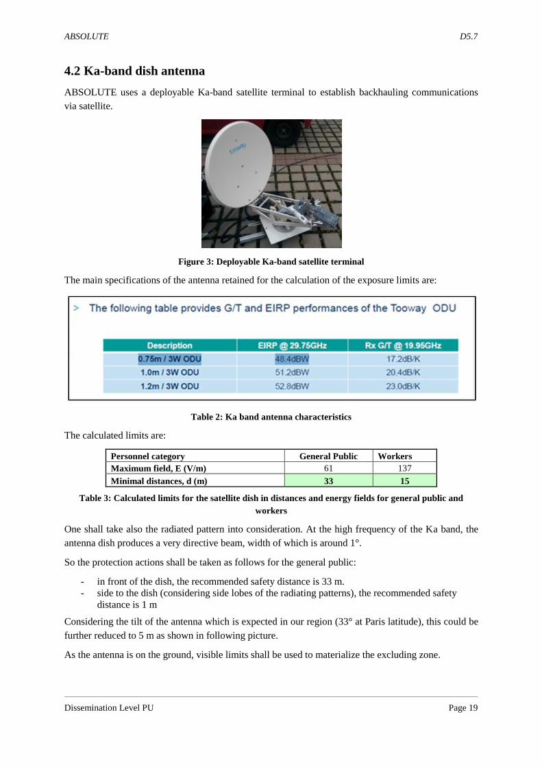
4.2 Ka-band dish antenna
ABSOLUTE uses a deployable Ka-band satellite terminal to establish backhauling communications
via satellite.
Figure 3: Deployable Ka-band satellite terminal
The main specifications of the antenna retained for the calculation of the exposure limits are:
Table 2: Ka band antenna characteristics
The calculated limits are:
Personnel category General Public Workers
Maximum field, E (V/m) 61 137
Minimal distances, d (m) 33 15
Table 3: Calculated limits for the satellite dish in distances and energy fields for general public and
workers
One shall take also the radiated pattern into consideration. At the high frequency of the Ka band, the
antenna dish produces a very directive beam, width of which is around 1°.
So the protection actions shall be taken as follows for the general public:
- in front of the dish, the recommended safety distance is 33 m.
- side to the dish (considering side lobes of the radiating patterns), the recommended safety
distance is 1 m
Considering the tilt of the antenna which is expected in our region (33° at Paris latitude), this could be
further reduced to 5 m as shown in following picture.
As the antenna is on the ground, visible limits shall be used to materialize the excluding zone.
Page 20
ABSOLUTE D5.7
Dissemination Level PU Page 20
Figure 4: Safety computed zone for the satellite Ka-band terminal
-33,1
6
-29,8
5
-26,5
3
-23,2
1
-19,9
0
-16,5
8
-13,2
7
-9,9
5
-6,6
3
-3,3
2
0 3,3
2
6,6
3
9,9
5
13,2
7
16,5
8
19,9
0
23,2
1
26,5
3
29,8
5
33,1
6
-15,0061,00137,00 -16,58
-13,27
-9,95
-6,63
-3,32
0,00
3,32
6,63
9,95
13,27
16,58
137,00-147,00
61,00-137,00
-15,00-61,00
emitter
Horizintal distance (m)
Vertic
al d
ista
nce (m
)
-5,0
0
-4,5
0
-4,0
0
-3,5
0
-3,0
0
-2,5
0
-2,0
0
-1,5
0
-1,0
0
-0,5
0
0 0,5
0
1,0
0
1,5
0
2,0
0
2,5
0
3,0
0
3,5
0
4,0
0
4,5
0
5,0
0
-15,0061,00137,00 -2,50
-2,00
-1,50
-1,00
-0,50
0,00
0,50
1,00
1,50
2,00
2,50
137,00-147,00
61,00-137,00
-15,00-61,00
emitter
Horizintal distance (m)
Ve
rtical d
ista
nc
e (m
)
5m
> 2,5 m
33°
Page 21
ABSOLUTE D5.7
Dissemination Level PU Page 21
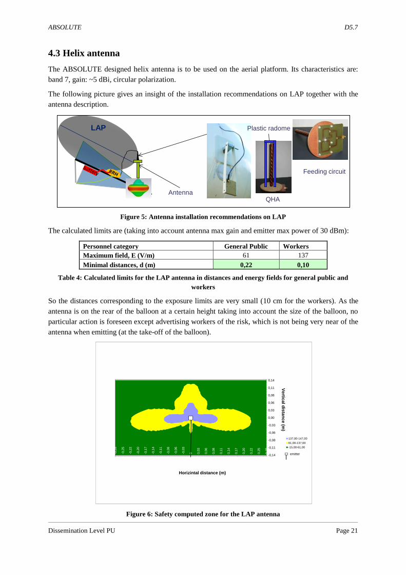
4.3 Helix antenna
The ABSOLUTE designed helix antenna is to be used on the aerial platform. Its characteristics are:
band 7, gain: ~5 dBi, circular polarization.
The following picture gives an insight of the installation recommendations on LAP together with the
antenna description.
Figure 5: Antenna installation recommendations on LAP
The calculated limits are (taking into account antenna max gain and emitter max power of 30 dBm):
Personnel category General Public Workers
Maximum field, E (V/m) 61 137
Minimal distances, d (m) 0,22 0,10
Table 4: Calculated limits for the LAP antenna in distances and energy fields for general public and
workers
So the distances corresponding to the exposure limits are very small (10 cm for the workers). As the
antenna is on the rear of the balloon at a certain height taking into account the size of the balloon, no
particular action is foreseen except advertising workers of the risk, which is not being very near of the
antenna when emitting (at the take-off of the balloon).
Figure 6: Safety computed zone for the LAP antenna
LAP
Antenna
Feeding circuit
QHA
Plastic radome
-0,2
8
-0,2
5
-0,2
2
-0,2
0
-0,1
7
-0,1
4
-0,1
1
-0,0
8
-0,0
6
-0,0
3
0 0,0
3
0,0
6
0,0
8
0,1
1
0,1
4
0,1
7
0,2
0
0,2
2
0,2
5
0,2
8
-15,0061,00137,00 -0,14
-0,11
-0,08
-0,06
-0,03
0,00
0,03
0,06
0,08
0,11
0,14
137,00-147,00
61,00-137,00
-15,00-61,00
emitter
Horizintal distance (m)
Vertic
al d
ista
nce (m
)
Page 22
ABSOLUTE D5.7
Dissemination Level PU Page 22
4.4 Dipole antenna array
The ABSOLUTE designed collinear antenna is to be used on a mast or a tripod at the PLMU
subsystem. Its main characteristics are: Band 7, max gain: 9 dBi, aperture: omni x 15°.
Figure 7: Antenna installation recommendations on a tripod
The calculated limits are (taking into account antenna max gain and emitter max power of 30 dBm):
Personnel category General Public Workers
Maximum field, E (V/m) 61 137
Minimal distances, d (m) 0.40 0,18
Table 5: Calculated limits for the tripod antenna in distances and energy fields for general public and
workers
No particular action is to be taken on a mast (see picture below with a 8 m mast) but if a tripod is used,
access to near vicinity of the tripod should be restricted (40 cm).
Figure 8: Safety computed zone for the tripod antenna
TeNB
Collinear antenna
PLMU
-0,5
0
-0,4
5
-0,4
0
-0,3
5
-0,3
0
-0,2
5
-0,2
0
-0,1
5
-0,1
0
-0,0
5
0 0,0
5
0,1
0
0,1
5
0,2
0
0,2
5
0,3
0
0,3
5
0,4
0
0,4
5
0,5
0
-15,0061,00137,00 7,75
7,80
7,85
7,90
7,95
8,00
8,05
8,10
8,15
8,20
8,25
137,00-147,00
61,00-137,00
-15,00-61,00
emitter
Horizintal distance (m)
Vertic
al d
ista
nce (m
)
Page 23
ABSOLUTE D5.7
Dissemination Level PU Page 23
5 Conclusion
This deliverable has provided a brief overview of the qualification and certifications procedures for a
latter exploitation of the ABSOLUTE system.
As has been seen in Chapter 2, the Helikite aerial platform to be used for the demonstration also fulfils
some specific qualification and certification procedures in terms of materials, deployment, safety
regulations, personal training... Those procedures also apply to the launch system of the platform.
Furthermore a brief overview of the EASA airworthiness processes has been presented in Chapter 3 so
as to provide a general idea of what would be required to certify avionics equipment, such as an ETSO
authorization.
Finally Chapter 4 provided some guidance for public and worker safety towards antenna radiation. The
metric computed here was the maximum exposure distance of the workers and public for the different
antennas that will be used within ABSOLUTE. Particular care is required for using the satellite dish
antenna, as a recommended safety distance of 33 m is necessary in front of the dish and 1m on the side
(considering side lobes of the radiating patterns).
Page 24
ABSOLUTE D5.7
Dissemination Level PU Page 24
Appendix – 1
CONSTRUCTION AND STRUCTURAL MATERIAL STRENGTHS FOR 34 CUBIC METRE DESERT
STAR HELIKITE
Page 25
ABSOLUTE D5.7
Dissemination Level PU Page 25
Appendix – 2
ABSOLUTE HELIKITE OPERATIONS RISK ASSESSMENT
Page 27
ABSOLUTE D5.7
Dissemination Level PU Page 27
ABSOLUTE HELIKITE OPERATIONS RISK ASSESSMENT
COMPANY NAME: Allsopp Helikites Ltd ASSESSMENT CARRIED OUT BY: Sandy Allsopp DATE: 10/12/2014 HAZAR
D SEVERITY 1 Insignificant 2 Minor 3 Moderate 4 Serious injury or Death
HAZARD LIKELIHOOD 1 Rare 2 Unlikely 3 Possible 4 Likely
HAZARD RISK 1-2 Very Low 3-4 Low
5-6 Medium 7-8 High
Operation What are the hazards?
Who might be harmed and
how?
Hazard Severity
1 - 4
Hazard Likelih
ood 1 - 4
Hazard Combin
ed Score 2 - 8
Hazard Reduction Strategies
Surveying launch site before deployment
Uneven terrain. Wildlife. Snake
bites. Insect and scorpion stings.
Operators. Site surveyors.
Tripping up. Falling down.
Attack by wildlife.
2 1 3 Study terrain on map first. Look out. Be aware of wildlife. Have safe vehicle refuge. Have anti-venom and first aid kit available.
Do not operate alone if possible.
Hammering in ground anchors
Hammer injuries Operators, by hammering
mistakes
2 1 3 Hammering tuition and practice. Wear safety gloves and safety goggles. Inspect the
ground. Deploying air-inflatable Lifting injuries Operators, by 1 1 2 Use proper lifting techniques. Wear safety
Page 28
ABSOLUTE D5.7
Dissemination Level PU Page 28
Helibase launch pad lifting. gloves.
Lifting Helikite onto Helibase
Lifting injuries Operators, by lifting.
1 1 2 Use proper lifting techniques. Wear safety gloves.
Moving helium cylinders Lifting injuries. Crush injuries.
Operators, by lifting and dropping cylinders.
1 2 3 Use proper lifting techniques and equipment, wearing safety gloves and steel capped boots. Have first aid kit easily available.
Moving winch Lifting injuries. Crush injuries.
Operators, by lifting small winches or
positioning large trailed winches.
2 1 3 Use proper lifting techniques and equipment, wearing steel capped boots and safety
gloves. Obeying winch deployment instructions. Winch to have proper lifting
eyes, wheels if required, and handles. Have first aid kit easily available.
Fitting and operating the gas regulator valve
Gas regulator valve faulty or not
suitable for the operation.
Operators. Gas regulator valve
may shear off the cylinder when gas is released from
cylinder into valve.
3 1 4 Ensure regulator valve is suitable for the climate and helium cylinder. Ensure the valve
is properly secured onto the cylinder. Hold head away from the valve when releasing gas
from cylinder.
Filling the Helikite balloon with helium gas.
Gas hose may split. Gas may leak
from balloon or cylinder or hose.
Operators. Gas hose splitting
may cause injury.
4 1 5 Ensure hose is suitable to withstand expected gas pressures. Do not exceed
correct hose gas pressure.
Filling Helikite in an enclosed place
Helium gas may escape from Helikite, or
cylinder, or filling hose and displace
the air in the enclosed space.
Operators. Inhaling helium gas may cause
asfixiation.
4 1 5 Ensure that any enclosed space has good ventilation when filling or storing Helikites.
Do not inhale helium gas.
Page 29
ABSOLUTE D5.7
Dissemination Level PU Page 29
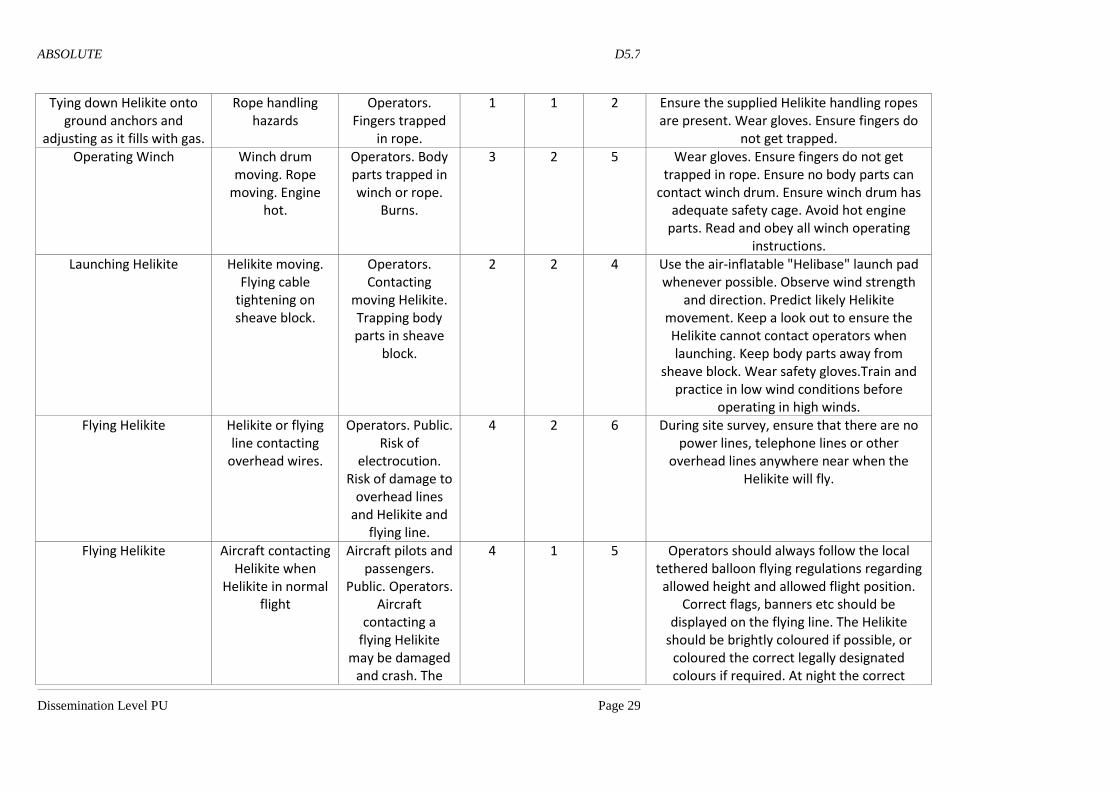
Tying down Helikite onto ground anchors and
adjusting as it fills with gas.
Rope handling hazards
Operators. Fingers trapped
in rope.
1 1 2 Ensure the supplied Helikite handling ropes are present. Wear gloves. Ensure fingers do
not get trapped. Operating Winch Winch drum
moving. Rope moving. Engine
hot.
Operators. Body parts trapped in winch or rope.
Burns.
3 2 5 Wear gloves. Ensure fingers do not get trapped in rope. Ensure no body parts can
contact winch drum. Ensure winch drum has adequate safety cage. Avoid hot engine
parts. Read and obey all winch operating instructions.
Launching Helikite Helikite moving. Flying cable
tightening on sheave block.
Operators. Contacting
moving Helikite. Trapping body parts in sheave
block.
2 2 4 Use the air-inflatable "Helibase" launch pad whenever possible. Observe wind strength
and direction. Predict likely Helikite movement. Keep a look out to ensure the Helikite cannot contact operators when launching. Keep body parts away from
sheave block. Wear safety gloves.Train and practice in low wind conditions before
operating in high winds. Flying Helikite Helikite or flying
line contacting overhead wires.
Operators. Public. Risk of
electrocution. Risk of damage to
overhead lines and Helikite and
flying line.
4 2 6 During site survey, ensure that there are no power lines, telephone lines or other
overhead lines anywhere near when the Helikite will fly.
Flying Helikite Aircraft contacting Helikite when
Helikite in normal flight
Aircraft pilots and passengers.
Public. Operators. Aircraft
contacting a flying Helikite
may be damaged and crash. The
4 1 5 Operators should always follow the local tethered balloon flying regulations regarding allowed height and allowed flight position.
Correct flags, banners etc should be displayed on the flying line. The Helikite
should be brightly coloured if possible, or coloured the correct legally designated colours if required. At night the correct
Page 30
ABSOLUTE D5.7
Dissemination Level PU Page 30
public or operators may be
harmed by crashing aircraft
lighting regulations for moored tethered balloons must be followed. Air traffic control permission must be sought if flying above an altitude where it is required. Also, in certain countries, aerostats above certain masses
and volumes need air traffic control permission to fly at any height at all.
Flying Helikite Helikite breaking away from tether
and flying off.
Public. Operators. Aircraft pilots and
passengers. Aircraft
contacting a free flying Helikite
may be damaged and crash. The
public or operators may be
harmed by crashing aircraft
2 1 3 Ensure the flying line has a manufacturers rated breaking strain at least 5 time greater
than the expected pull from the Helikite. Ensure that a certified, legal and functioning Emergency Balloon Cut-Down-Device is on
the Helikite balloon. If Helikite flies off, note altitude, speed and heading and contact the
local Air Traffic Control Authorities immediately and have their phone number
easily available.
Flying Helikite Flying line breaking
Operators. Broken end of
flying line whipping back
down onto operator.
1 2 3 Ensure the flying line has a manufacturers rated breaking strain at least 5 time greater
than the expected pull from the Helikite. Always ensure Dyneema® or Spectra® flying
line is use, because they have very little stretch and so do not rebound back if cut
(unlike nylon or steel). Ensure Helikite is not flown in winds that will cause too much
strain on the line. Measure strain on line with a suitable cable strain gauge.
Carrying Equipment Equipment falling off.
Public. Operators. Items falling on
them.
4 1 5 Ensure equipment is well secured to Helikite. Ensure equipment has safety line attached. Ensure nobody goes under Helikite when
flying.
Page 31
ABSOLUTE D5.7
Dissemination Level PU Page 31
Landing Helikite Rope handling hazards. Contact
hazards.
Operators. Body parts, especially fingers may get
trapped in handling lines.
Helikite may hit somebody when
close to the ground.
2 2 4 Observe wind strength and direction. Predict likely Helikite movement. Keep a look out to ensure the Helikite cannot contact operators
when landing. Keep body parts away from sheave block. Ensure body parts do not get
trapped in handling ropes. Wear safety gloves. Train and practice in low wind
conditions before operating in high winds.
Deflating Helikite Gas inhalation hazards.
Operators. Inhaling helium gas may cause
asfixiation.
4 1 5 Ensure this occurs in a very well ventilated environment. Preferably outside. Do not
inhale helium gas for any reason. Do not hold mouth or nose near venting gas exit plugs.
Packing up Helikite and equipment
Lifing injuries. Crush injuries. Trip
hazards.
Operators, by lifting and dropping cylinders.
Operators, by lifting small winches or
positioning large trailed winches.
Operators by tripping over equipment,
especially packing up in the dark
evenings.
2 3 5 Use proper lifting techniques and equipment, wearing safety gloves and steel capped
boots. Obeying winch deployment instructions. Be aware of trip hazards. Have
suitable storage equipment for all equipment. Take note of the position of equipment during the day, ready for the nightime. Provide good lighting for the
operating area. Avoid operating when too tired.
Page 33
ABSOLUTE D5.7
Dissemination Level PU Page 33
References
[1] EASA – Europe Aviation Safety Agency: https://www.easa.europa.eu/
[2] Regulation (EC) No 1592/2002 “on common rules in the field of civil aviation and
establishing a European Aviation Safety Agency”, https://www.easa.europa.eu/document-
library/regulations/regulation-ec-no-15922002
[3] EASA – Aircraft Certification: https://www.easa.europa.eu/easa-and-you/key-topics/aircraft-
certification
[4] EASA – Unmanned Aircraft Systems (UAS) and Remotely Piloted Aircraft Systems
(RPAS): https://www.easa.europa.eu/unmanned-aircraft-systems-uas-and-remotely-piloted-
aircraft-systems-rpas
[5] EASA – E.Y013-01, “Airworthiness Certification of Unmanned Aircraft Systems (UAS)”,
https://www.easa.europa.eu/document-library/policy-statements/ey013-01
[6] EASA – FO.ETSOA.00034, “Application form for European Technical Standard Order”,
https://www.easa.europa.eu/document-library/application-forms/foetsoa00034
Acknowledgement
(Mandatory Text) This document has been produced in the context of the ABSOLUTE project.
ABSOLUTE consortium would like to acknowledge that the research leading to these results has
received funding from the European Commission’s Seventh Framework Programme (FP7-2011-8)
under the Grant Agreement FP7-ICT-318632.