24
FPGA Partial FPGA Partial Reconfiguration Reconfiguration Presented by: Abelardo Jara- Berrocal HCS Research Laboratory College of Engineering University of Florida April 10 th , 2009
| Date post: | 13-Dec-2015 |
| Category: |
Documents |
| Upload: | eugene-kelley |
| View: | 222 times |
| Download: | 0 times |
FPGA Partial FPGA Partial ReconfigurationReconfiguration
Presented by: Abelardo Jara-Berrocal
HCS Research LaboratoryCollege of Engineering
University of FloridaApril 10th, 2009
2
Outline Introduction Partial Reconfiguration (PR) Overview Proposed Design Methodologies Framework analysis F4: Virtual Architecture for Partial Reconfiguration
and Design Automation for PR Design

3
General purpose I/O
System controller
FPGA
Configuration lines
Shared memory
Battery
Module A
Module B
Module A
Module BModule A
Module B
Module C
Introduction – Fully reconfigurable systems
Bitstreams storage
External I/O
Design station
Required design
1. Device too small for complex designs
Module C
Module B
Module A
Module B
Module A
Module C
Module C
Module B
Module A
Module C
2. Big full bitstreams (long reconfiguration time)
Config 1
Config 2
Config 3Config 1 RequestConfig 2 Request
3. Complete system operation is halted prior to reconfiguration
Doe
s’nt
fit Module C
Module B
disabled
disabled
enabled
enabled
disabled
disabled

4
Types of Modular Dynamic Reconfiguration: Static Partial Reconfiguration: Reconfiguring a portion of the device (changing the functionality) when the device
is inactive without affecting other areas of the device Dynamic Partial Reconfiguration (PDR): Reconfiguring a portion of the device while the remaining design is still
active and operating without affecting the remaining portion of the device. Virtex 4 and Virtex 5 devices support DPR
Introduction – Modular Reconfiguration
)
Reconfigurable region 1
Reconfigurable region 2

5
Partial Reconfiguration Partial Reconfiguration is useful for systems with
multiple functions that can time-share the same FPGA resources.
TERMINOLOGY Reconfigurable Region (PRR) Reconfigurable Module (PRM) Static Logic Bus Macro Partial Bitstream Merged Bitstream

6
Module A
Module C
Module B
Introduction – A sample PR architecture
FPGA
Bitstreams storage
Battery
External I/O
Module C
3. Smaller partial bitstreams
Module A request
1. System controller does not need to be placed in an external device2. Access to fast Internal Configuration Access Port (ICAP – 32 bits, 100 MHz)
4. No need to halt complete system when reconfiguring a module5. Time multiplexing of FPGA resources, load and unload HW modules on demand
Base system configuration
JTAG
Reconfigurable area
disabled
disabled
Co
ntr
oll
er
(Mic
rob
laze
)
ICAP
Fla
sh
co
ntr
oll
er
Module C
Module B
enabled
Module Aenableddisabled
Static area
Module A
Module B
7
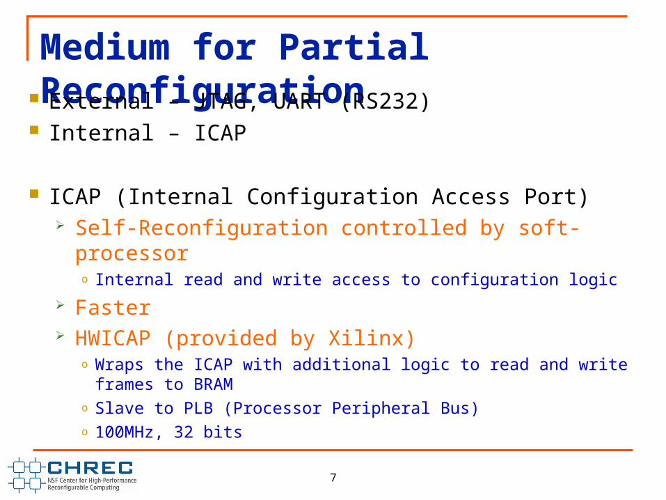
Medium for Partial Reconfiguration External – JTAG, UART (RS232)
Internal – ICAP
ICAP (Internal Configuration Access Port) Self-Reconfiguration controlled by soft-processor
o Internal read and write access to configuration logic
Faster HWICAP (provided by Xilinx)
o Wraps the ICAP with additional logic to read and write frames to BRAMo Slave to PLB (Processor Peripheral Bus)o 100MHz, 32 bits
8
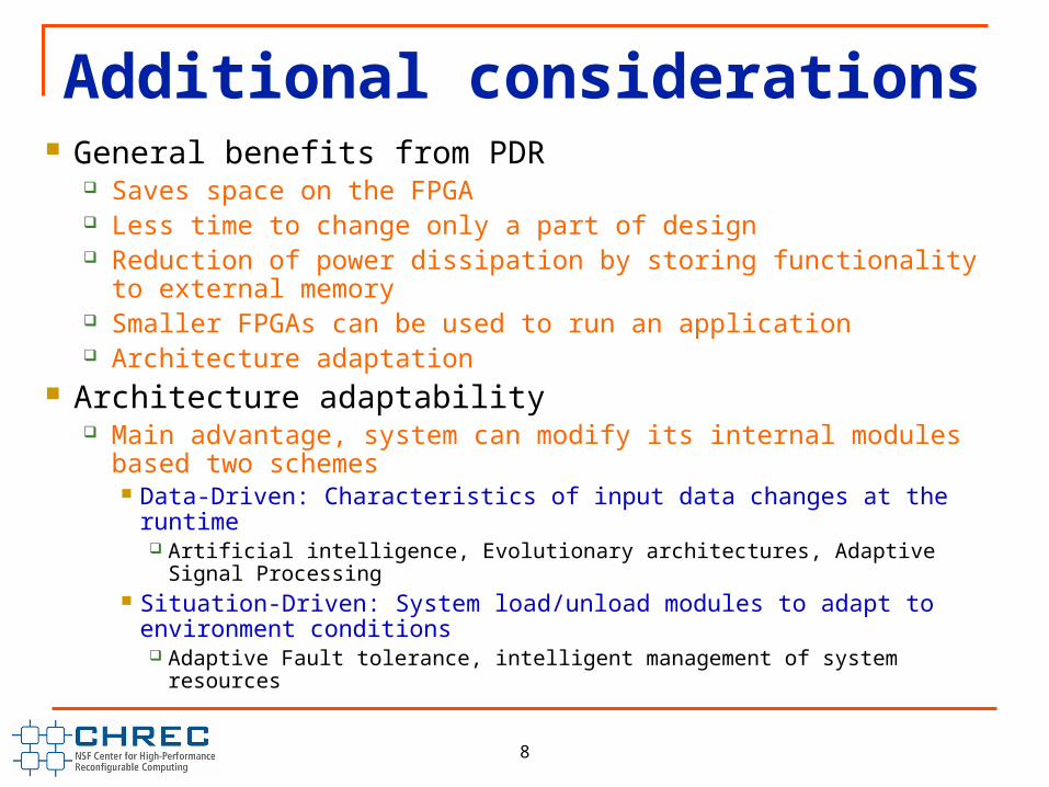
Additional considerations General benefits from PDR
Saves space on the FPGA Less time to change only a part of design Reduction of power dissipation by storing functionality to external
memory Smaller FPGAs can be used to run an application Architecture adaptation
Architecture adaptability Main advantage, system can modify its internal modules based two
schemes Data-Driven: Characteristics of input data changes at the runtime
Artificial intelligence, Evolutionary architectures, Adaptive Signal Processing Situation-Driven: System load/unload modules to adapt to environment
conditions Adaptive Fault tolerance, intelligent management of system resources

9
Bus Macros Bus Macros: Means of communication between PRMs and
static design All connections between PRMs and static design must pass
through a bus macro with the exception of a clock signal Type of Bus Macros
Tri-state buffer (TBUF) based bus macros Slice-based (or LUT-based) bus macros
Advantage of slice-based bus macros No signals lines should cross the border in partial
reconfiguration TBUFs – will ignore the boundaries Slice-based – signals not crossing boundaries

10
LUT-based Slice Macros

11
Co
ntr
oll
er
(Mic
rob
laze
)
ICAP
Fla
sh
co
ntr
oll
er
Introduction – Current PR Design Flow Steps
Partition the system into modules Define static modules and
reconfigurable modules Decide the number of PR regions
(PRRs) Decide PRR sizes, shapes and
locations Map modules to PRRs Define PRR interfaces, instantiate
slice macros for PRR interfaces
Many manual steps Design partitioning Number of PRRs PRR sizes, shapes and locations Mapping PRMs to PRRs Type and placement of PRR
interfaces
Module A
Module C
Module B
Static modules Reconfigurable Modules (PRMs)
12
FP
GA
# of PRRs?
PRR 1
PRR 2
Sta
tic r
egio
nStatic modules
Modules: A and B
Modules: C
De
sig
n
pa
rtiti
on
ing
De
sig
n
floo
rpla
nn
ing
a
nd
bu
dg
etin
g
12
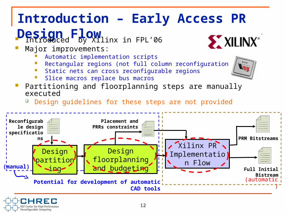
Introduction – Early Access PR Design Flow Introduced by Xilinx in FPL’06
Major improvements: Automatic implementation scripts Rectangular regions (not full column reconfiguration) Static nets can cross reconfigurable regions Slice macros replace bus macros
Partitioning and floorplanning steps are manually executed Design guidelines for these steps are not provided
(manual)
Placement and PRRs constraints
PRM Bitstreams
Design partitioning
Design floorplanning and budgeting
Xilinx PR Implementation
FlowFull Initial Bistream
Reconfigurable design
specifications
(automatic)Potential for development of automatic CAD tools

13
Introduction – Current PR design tools limitations
PR design is a very specialized task Only a physical level of support is provided
Architectural knowledge of the target device is a must Not very flexible, many design constraints
Partitioning and floorplanning steps are manually executed No performance sensitive design guidelines are provided No automatic heuristics based design flow is available too
Lack of abstraction from low level details

14
PR Overview – Taxonomy of PR systems design flows
PR Designs
MultipurposeSpecial purpose
Highly specialized systems design
All PRMs that will exist on the system are known at design time
Each PRR is independently optimized (size, shape, location, interface) based on the PRMs that will be mapped to it
Output is:
1) Floorplan defining a static region and a set of optimized PRRs
2) The set of PRMs that can be placed in each PRR (PRMs to PRRs mapping)
Not optimized for a specific application
PRMs required by the application are not known when designing the base system
Goal is to design a flexible and reusable base design that can be used for several different PR systems
Base system designer defines a set of PRRs with fixed shapes, sizes, locations and interfaces
Generated floorplan is used as input template for the PRMs implementation
15
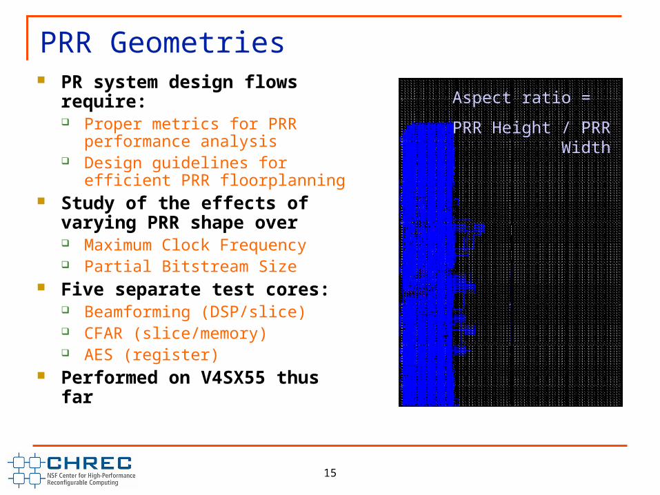
PRR Geometries PR system design flows require:
Proper metrics for PRR performance analysis
Design guidelines for efficient PRR floorplanning
Study of the effects of varying PRR shape over Maximum Clock Frequency Partial Bitstream Size
Five separate test cores: Beamforming (DSP/slice) CFAR (slice/memory) AES (register)
Performed on V4SX55 thus far
Aspect ratio =
PRR Height / PRR Width

16
Framework analysis – Beamforming (~125 MHz, 40%)
5022 slices 16 DSP48s 17 RAMB16s Baseline, non-PR performance = 1614 kB, 127.845 MHz
Clo
ck fr
eq
uen
cy (
MH
z)
Bits
trea
m s
ize
(kB
)
Aspect ratio Aspect ratio

17
Framework analysis – CFAR (~100 MHz, 16%)
2610 slices 2 DSP48s 34 RAMB16s Baseline, non-PR performance = 1001 kB, 103.616 MHz
Clo
ck fr
eq
uen
cy (
MH
z)
Bits
trea
m s
ize
(kB
)
Aspect ratio Aspect ratio

18
Framework analysis – AES (~80 MHz, 13.75%)
3634 slices 3943 registers 4 RAMB16s Baseline, non-PR performance = 1393 kB, 80.483 MHz
Clo
ck fr
eq
uen
cy (
MH
z)
Bits
trea
m s
ize
(kB
)
Aspect ratio Aspect ratio

F4: Virtual Architecture and Design Automation for Partial Reconfiguration
Abelardo JaraShaon Yousuft
Rohit KumarTerence FrederickCHREC Students
Dr. Ann Gordon-Ross
Dr. Alan D. George
UF ECE Faculty

20
Approach
Task 1: VA for PR Adaptive Embedded Systems
SCORES Inter-module Communication Architecture
VAPRES Multipurpose Base Embedded Platform
Initial Research on fast algorithms for online PRMs placement and scheduling
Task 2: PR Design Flow Automation
Framework to model and design PR systems
Identification of points in Xilinx PR Design Flow amenable for automation
Software tools (C/C++ programs/scripts) for automatable steps
Task 3: Bitstream Relocation
Port Bit Reloc to Microblaze
Context save and restore for PRMs
PR forApplicationDesigners
20

21
Background – VA for Adaptive PR Embedded Systems Multi-purpose base system platform to
build runtime-adaptive HW processing embedded systems Architectural support for on-demand HW
module loading/unloading HW modules can offer better
performance than SW modules Exploit increased parallelism Main bottleneck:
Inter-module communication flows through centralized controller
Can be alleviated by adding custom inter-module communication architecture
VA benefits: Adaptive base system platform
Response to environmental changes HW/SW partitioned applications
Time-shared virtual resources enable larger available area for system operations
Improved system resource utilization Case study application:
PR for Mobile Agents
SC
OR
ES
Co
ntr
oll
er a
nd
per
iph
eral
s
External memory
VA
PR
ES
Type A module
Type B module
Type A module
Type B target
Type A target
Free slot
e.g. Geographical area divided into 4 regions (one
processing node per region)
Adaptive embedded system at each processing node
Target B
Target A
21

222222
VAPRESVAPRES- (Virtual Architecture for Partially Reconfigurable Adaptive Embedded Systems)
VAPRES Architectural Components Partially Reconfigurable Regions (PRRs)
Independently clocked using BUFRs PR modules (PRMs) can span multiple PRRs
Controlling agent (Microblaze): Dynamic module placement and scheduling Module control and context save/restore Partial reconfiguration through ICAP Communication with other VAPRES nodes
VAPRES Motivations/Benefits Embedded base architecture for
multi-purpose PR systems Facilitates dynamic HW modules
placement and scheduling Provides dynamic module frequency
scaling Computing power can be distributed
among VAPRES-based nodes
Microblaze
PRR1 PRR2 PRR3 PRR4
Network-on-chip (SCORES)
Fast Simplex Link (FSL)
PLB
Bus
ICAP
Flashcontroller
UART
USB
BUFR
Switch
Sha
red mem
ory
InterfaceInterfaceInterfaceInterfaceNetwork
Network (other VAPRESnodes)
Network (other VAPRESnodes)
PRM A
2323
Ce
ntr
al
C
on
tro
llin
g A
ge
nt
ICAP
Me
m c
on
tro
lle
r
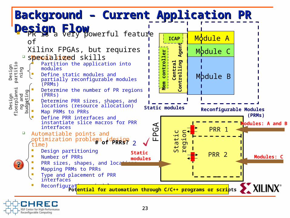
Background – Current Application PR Background – Current Application PR Design FlowDesign Flow
Manual steps Partition the application into modules Define static modules and partially
reconfigurable modules (PRMs) Determine the number of PR regions
(PRRs) Determine PRR sizes, shapes, and
locations (resource allocation) Map PRMs to PRRs Define PRR interfaces and instantiate
slice macros for PRR interfaces Automatiable points and optimization
problems (design-time) Design partitioning Number of PRRs PRR sizes, shapes, and locations Mapping PRMs to PRRs Type and placement of PRR interfaces Reconfiguration schedule
Module A
Module C
Module B
Static modules Reconfigurable Modules (PRMs)
12 FP
GA
# of PRRs?
PRR 1
PRR 2
Sta
tic r
egio
n
Static modules
Modules: A and B
Modules: C
Des
ign
part
ition
ing
Des
ign
floor
plan
ning
an
d bu
dget
ing
Potential for automation through C/C++ programs or scripts
PR is a very powerful feature of Xilinx FPGAs, but requires specialized skills

24
Questions


![[Mcgraw-hill] Resistencia de Materiales - Ortiz Berrocal, Luis](https://static.documents.pub/doc/80x56/56d6bf141a28ab301694ca1b/mcgraw-hill-resistencia-de-materiales-ortiz-berrocal-luis.jpg)


