FRAGMENT HAZARDS FROM FAILURES OF PRESSURISED LIQUEFIED GAS VESSELS P L Holden* and A B Reeves* A large number of failures of pressurised liquefied gas vessels producing missiles have occurred. The modes and patterns of failure, which dictate whether fragments are projected and the number of pieces the vessel breaks into are discussed. Data has been collected on over 100 vessel failures, mainly involving LPG and failing due to flame impingement. This data has been analysed with particular reference to number, range and direction of fragments. Spherical and cylindrical vessel geometries are considered separately. Other parameters have been taken into account where sufficient data is available. End caps from cylindrical vessels are given particular attention, because of their tendency to form rocketing vessel sections. Although most of the cylindrical vessels concerned were transport containers, there are no grounds for supposing this factor is important. The data is particularly useful since most theoretical assessment methods for missile velocity are based on ideal gas behaviour and so cannot be used for liquefied gases. INTRODUCTION In the context of this paper, "missiles" are objects or parts of objects that have received kinetic energy and as a result, are projected from their original location to another. An aspect which often needs to be considered in risk assessment is the chance of a missile damaging a particular target or targets. In the case of Major Hazard plant the target would usually be a plant containing hazardous materials and the degree of damage involved would be a loss of containment. Missiles represent an interactive mechanism for escalation of an event. The assessment of missile hazards involves four stages:- (i) Identification of potential missile sources, on the plant itself and external to the plant. (ii) The number of missiles produced by each event and the probability of each event occurring. (iii) The probability of a particular missile following a trajectory such that it hits the target of interest. (iv) The probability of the target being damaged on impact. An important missile generation mechanism is the rupture of pressurised equipment. The theoretical models which are available for prediction of fragment velocities from pressure vessel failure are by no means fully developed. Often they are based on ideal gas behaviour and so are of doubtful value for liquefied gases. Even if flashing liquid behaviour is modelled input *Safety and Reliability Directorate, UKAEA. 205
Transcript
FRAGMENT HAZARDS FROM FAILURES OF PRESSURISED LIQUEFIED GAS VESSELS
P L Holden* and A B Reeves*
A large number of failures of pressurised liquefied gas vessels producing missiles have occurred. The modes and patterns of failure, which dictate whether fragments are projected and the number of pieces the vessel breaks into are discussed. Data has been collected on over 100 vessel failures, mainly involving LPG and failing due to flame impingement. This data has been analysed with particular reference to number, range and direction of fragments. Spherical and cylindrical vessel geometries are considered separately. Other parameters have been taken into account where sufficient data is available. End caps from cylindrical vessels are given particular attention, because of their tendency to form rocketing vessel sections. Although most of the cylindrical vessels concerned were transport containers, there are no grounds for supposing this factor is important. The data is particularly useful since most theoretical assessment methods for missile velocity are based on ideal gas behaviour and so cannot be used for liquefied gases.
INTRODUCTION
In the context of this paper, "missiles" are objects or parts of objects that have received kinetic energy and as a result, are projected from their original location to another. An aspect which often needs to be considered in risk assessment is the chance of a missile damaging a particular target or targets. In the case of Major Hazard plant the target would usually be a plant containing hazardous materials and the degree of damage involved would be a loss of containment. Missiles represent an interactive mechanism for escalation of an event. The assessment of missile hazards involves four stages:-
(i) Identification of potential missile sources, on the plant itself and external to the plant.
(ii) The number of missiles produced by each event and the probability of each event occurring.
(iii) The probability of a particular missile following a trajectory such that it hits the target of interest.
(iv) The probability of the target being damaged on impact.
An important missile generation mechanism is the rupture of pressurised equipment. The theoretical models which are available for prediction of fragment velocities from pressure vessel failure are by no means fully developed. Often they are based on ideal gas behaviour and so are of doubtful value for liquefied gases. Even if flashing liquid behaviour is modelled input
*Safety and Reliability Directorate, UKAEA.
205
IChemE SYMPOSIUM SERIES No. 93
assumptions still have to be made (eg on number of fragments produced and launch angles) and these must be based on empirical evidence or experience. However, there is a large amount of accident experience in which missiles have been generated, particularly by failure in fire of vessels containing pressurised liquefied gases. Data from such incidents has been collected and analysed (1). This paper presents a summary of this data and produces some generalised conclusions on the various parameters which have been studied.
CAUSATION MECHANISMS
There is a wide range of mechanisms capable of causing pressure vessel rupture, which can be categorised into two main types:
(i) Failure under excessive pressure loading, either due to a gradual increase in pressure (eg hydrostatic pressure from thermal expansion) or explosive overpressurisation (eg rapid phase transition, detonation of reactive materials, exothermic runaway reaction, combustion).
(ii) Failure under normal pressure loading either spontaneously (eg due to defects) or by boundary weakening (eg embrittlement, corrosion, impact, heating).
A particularly important failure mechanism for liquefied pressurised gas vessels Is boundary weakening by flame impingement on the vessel wall above the liquid level. In this paper we have referred to this scenario as a BLEVE (Boiling Liquid Expanding Vapour Explosion). There is some controversy over the use of this acronym, as some authors use it in its literal sense to signify any sudden failure of a vessel containing a flashing liquid. An I Chem E working party has recommended (2) that the term should be used in its most usual sense, to mean the flame impingement caused rupture of a liquefied flammable gas pressure vessel, producing a fireball and, usually, rocketing fragments. Thus, unlike other authors (3), we have not classified the rupture of an LPG rail car at Waverly as a BLEVE, even though a fireball was produced on rupture and the consequences were indistinguishable from those associated with a BLEVE. (In this case the cause of failure was probably an Increase in internal pressure, due to increased ambient temperature, which led to propagation of a crack present from the earlier impact of derailment).
DAMAGE CAUSED BY VESSEL FRAGMENTS
Although only one of the numerous mechanisms which can cause pressure vessel rupture, BLEVEs provide some good examples of the potential for damage. Although the fireball is the principal threat to life, it is interesting to note that a significant proportion of the fatalities from BLEVEs in the USA have been attributed to missiles rather than the fireball. Most of the 11 killed and 10 injured amongst on-lookers at Deer Lake, Pennsylvania, when an LPG road tanker underwent a BLEVE in 1959, were victims of a rocketing tank section (4). At a range of somewhat more than 200m they were outside the thermal hazard range for that particular incident. The deaths of three fire fighters and a civilian bystander were also attributed to vessel fragments from an LPG storage vessel BLEVE at West St Paul, Minnesota, in 1974 (5). Indeed, recommended evacuation distances for liquefied gas vessels involved in fires are based on missile range rather than thermal hazard range (6), since the potential missile range exceeds the thermal radiation hazard range.
In addition to the direct threat to life from vessel fragments, missiles present a potential for escalation of an event. Accident experience indicates
206
IChemE SYMPOSIUM SERIES No. 93
that, not surprisingly, pipework and thin-walled vessels are particularly vulnerable. However, pressure vessels are also liable to suffer severe damage, as was the case at Crescent City. In this incident one of six propane rail tank cars which ruptured in BLEVEs produced two main fragments - one half of the vessel was projected intact and the other half as a flattened section.(7) One of these fragments punctured the head of another propane tank car and the other fragment sheared the housing and valves off a third propane tank car.(8) In a similar event at Laurel, a propane tank car, impacted by an end tub from a BLEVE of another tank car, sustained a major failure which caused total loss of containment - an 8ft wide flap extending half-way around the vessel circumference (9).
Escalation of incidents may also occur due to important ancillary equipment being affected, or simply spreading of fire. At Texas City, in 1978 a fragment from an LPG sphere which had undergone a BLEVE travelled 210m and hit the site fire water supply tank (10)• Over the next 20 minutes another 10 pressure vessels ruptured. Other fragments caused outbreak of fire in nearby plant and tank farms - quite a common occurrence in BLEVEs as burning hydrocarbon is often transported with the fragment. At Puebla, Mexico, in 1977, a rocketing fragment arising from a BLEVE of a vinyl chloride monomer storage vessel hit the main site water tank and carried it bodily over the perimeter fence (10). At Laurel a fragment from one of the ruptured railcars hit a pumphouse, cutting an 8 inch main and reducing water pressure available to the fire services (11). These types of event are typical of the interaction or escalation hazard posed by missiles.
MECHANICS OF VESSEL FAILURE
Importance of Failure Mode
The failure mode of a vessel has particular importance to missile generation. The number of fragments produced and their directional distribution may be dictated by the failure mechanism. The available energy will depend on the failure cause and this parameter may have an effect on the possible fragment range via the energy imparted to the fragment.
The mechanism by which cracks propagate and the speed of propagation are clearly important factors which may determine whether a vessel disintegrates on failure or just splits open. The number of fragments may also depend on those parameters in addition to whether any fragments are projected at all.
Brittle fractures propagate rapidly and have a tendency to branch, thus producing multiple fractures and the possibility of fragmentation of a vessel into a large number of pieces. Ductile fractures propagate at a slower speed than brittle fractures and do not branch into multiple fractures, therefore there is little likelihood of a vessel disintegrating into many fragments by this mechanism. Appreciable deformation and also reduction in thickness usually occurs during ductile fracture, unlike brittle fracture.
Failures of Cylindrical Vessels, including BLEVEs
Vessel failure can usually be attributed to weakening of the vessel or exposure of the vessel to conditions outside its design range. One mechanism for failure of pressure vessels which is particularly important in the context of liquefied gases is flame impingement, leading to a BLEVE.
Hundreds of pressure vessels have failed in BLEVEs, many of them rail tank cars in the USA. In such incidents, sections of the failed vessel have been
207
IChemE SYMPOSIUM SERIES No. 93
projected considerable distances. Frequently complete sections of a vessel, including an end cap, have been projected. These are often termed "rocketing fragments" as expulsion of the contents can literally propel the fragment in rocket fashion.
The initiating fracture in a cylindrical vessel tends to be in an axial direction, normal to the hoop stress. In fire engulfment situations, ductile propagation would generally be expected. For rocketing fragments to be produced, the axial fracture must eventually change direction to travel circumferentially, thus encircling the vessel and producing an 'end-tub'. Although most commonly observed in BLEVEs, end tub sections can be formed whatever the cause of the initial fracture and whether it is brittle or ductile. Accident experience clearly illustrates that axially propagating fractures can and generally do turn to encircle the vessel circumferentially.
A variety of possibilities exist for failure patterns, depending mainly on the point of initiation and whether one or two circumferential cracks occur. A very useful classification scheme for failure patterns was given by the Association of American Railroads (7).
Although the majority of incident experience involves transport containers there is no reason to suppose that the failure patterns will be any different in storage vessels. Several of the incidents covered in this paper have involved the failure of storage vessels. In the incident experience gathered, the patterns of fracture propagation and eventual failure configurations, have been similar for both cases.
In the case of spherical vessels there is no preferential direction for propagation and there are no end-caps which can form rocketing fragments.
CYLINDRICAL LIQUEFIED GAS VESSEL DATA
Probability of Fragment Projection on Failure
The data sample includes information on 130 major failures of horizontal cylindrical storage and transport vessels. In some cases the only information available is whether fragments were projected or not. Although in many cases some further information is available, on number of fragments projected, ranges, directions etc, there are relatively few cases for which the data is complete enough to contribute to an analysis of all of these parameters. Unfortunately data on fragment size or mass was so patchy that systematic analysis was not possible.
The 130 major failures break down as follows:
Fire events - fragments projected 89 Fire events - no fragments projected 24 Non-fire events - fragments projected 17
No attempt has been made to include non-fire events which cause failure without fragment projection as a tendency to under report punctures due to impact which do not propagate is expected. This may also be the case for the second of the two types of failure which can occur due to heating leading to failure by boundary weakening, without fragment projection:
(i) the failure propagates axially to the extent that a major opening is formed or the vessel even ends up as one virtually flattened section.
208
IChemE SYMPOSIUM SERIES No. 93
(ii) the failure remains local to the vicinity of failure initiation, producing a hole.
Notwithstanding this, the proportion of events involving fire where failure has occurred and fragments were projected is derived from this data sample to be 89/113, ie approximately 0.8. Of the 24 events which did not project fragments 10 were cases in which the failure was restricted to the overheated area, the remainder produced flattened plates.
This data sample excludes many well known incidents for which the number of failed vessels which projected fragments does not appear to be known, for example Port Newark (7/7/51) where 70 LPG storage vessels failed, many projecting fragments.
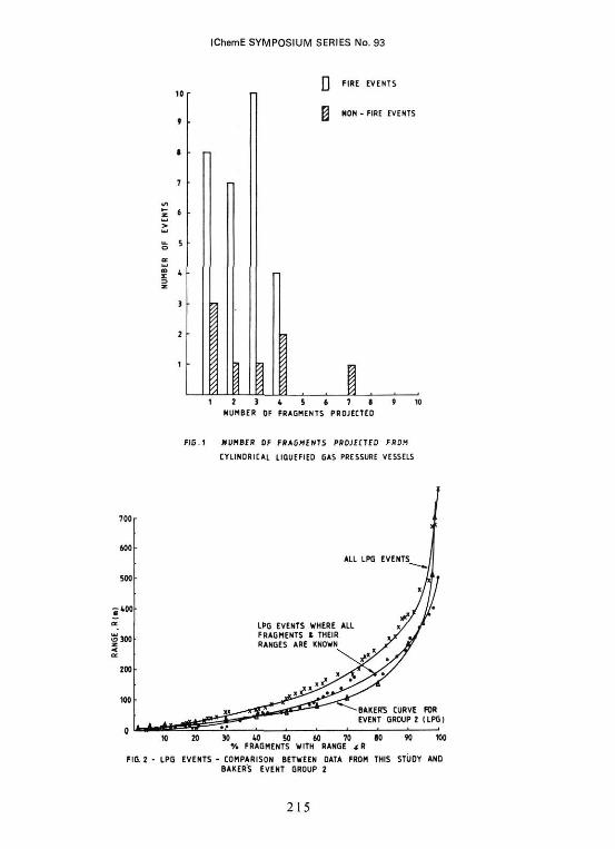
Number of Fragments Projected
The discussion on fracture patterns would lead us to expect that, at least in the case of ductile fractures, the vessel will generally break up into a small number of pieces. Fig 1 shows the data for fire and non-fire events. In order to ensure a consistent data sample only fragments from the vessel shell are counted. In particular, projected items associated with means of transportation are not included. All of the 23 fire events projected 1, 2, 3 or 4 fragments. This excludes the fire engulfment test at White Sands which projected some 10 vessel fragments on failure (12). This appears to be completely anomalous compared with the accident data, possibly due to differences between test and accident conditions. Only one of the 8 non-fire events projected more than 4 fragments - an impact induced, brittle fracture of an ammonia rail car at Crete, Nebraska, which projected 7 pieces.(13) The cases where one fragment was projected can, in the extreme, refer to projection of virtually the entire vessel as in the case of the impact punctured LPG vessel at Fertile, Minnesota (14).
The mean number of fragments for non-fire and fire events are very similar, although clearly the possibility of brittle fracture means that a number significantly greater than the mean can be projected.
For BLEVE events which do project fragments, however, it would be reasonable to assume that not more than 4 vessel fragments will be projected. For non-fire events the data Is sparse, but the approach adopted in the first Canvey Report (15) (ie assume 6 fragments projected) appears to be a reasonable one, likely to be conservative in most cases and rarely likely to lead to order of magnitude inaccuracies.
Analysis of Fragment Range Data for Cylindrical Vessels
The data sample includes information on the range of 153 fragments from 96 cylindrical liquefied gas vessel failures, which resulted from 56 separate incidents spanning a period of 21 years. The sample covers a variety of types of event involving a range of liquefied gases, including LPG, ammonia, vinyl chloride monomer, and ethylene oxide.
The majority of the incidents involved LPG and Fig 2 shows three plots of range, R, against the cumulative percentage of fragments with range <R;
(i) All LPG events - this includes cases where only the furthest fragment range is quoted in the literature. The plot is therefore biased towards overestimating fragment range.
209
iChemE SYMPOSIUM SERIES No. 93
(ii) LPG events where all fragments and their ranges are known - this more limited sample does not include the extremes of range known to be possible.
(iii) A comparative curve from an earlier published study (13).
The cumulative percentage against range presentation is similar to that adopted by Baker (13) for analysis of a much smaller data sample (9 events where all the fragment ranges were known compared to this sample of 34 such events). Baker plotted his results on probability - log paper. The results are presented on linear axes in this paper. Logarithmic plots generally give a good fit over most of the range span but do not fit well at the extremes of range. The results of this study are very similar to Baker's study, with approximately 80% of fragments from LPG vessel failures travelling less than 200m.
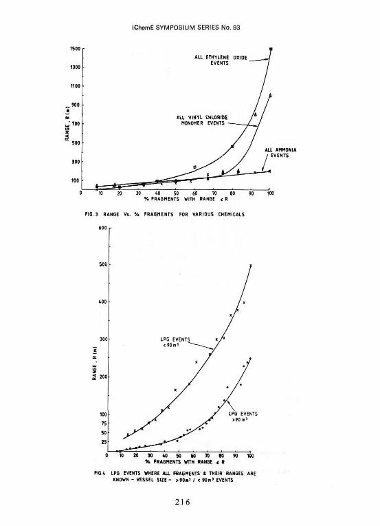
Fig 3 shows the available data for ethylene oxide, vinyl chloride monomer and ammonia. As with the "all events" LPG curve on Fig 2, there will probably be a tendency to overestimate fragment range because, where partial information is available, it is likely to include cases where only the maximum fragment range is known from an event projecting several fragments. Ethylene oxide vessel fragments appear to travel further than LPG, VCM or ammonia vessel fragments, possibly because of the potential for energetic chemical reactions in accident situations. The ammonia curve does not exhibit the usual pattern of a small percentage of fragments projected very long ranges but this may be due to the small data sample.
The considerable amount of LPG vessel data enables analysis of the effects on fragment range of several parameters-, including vessel capacity, event type and fragment type. Fig 4 shows a clear tendency for fragments from vessels with capacity less than 90 m3 to travel further than fragments from larger vessels. This tendency is maintained if the data is broken down further in terms of vessel capacity. Although several reasons for this could be postulated, further work is required to provide substantiation and an adequate explanation.
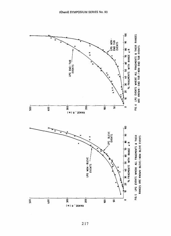
The fragment range data for BLEVE and non-BLEVE LPG events is compared in Fig 5. There is a marginal tendency for fragments from non-BLEVE events to travel further. This finding is perhaps somewhat surprising as BLEVEs will generally be more energetic events due to heating. It may be due to the mechanics of vessel failure.
Comparison between "end tub" and other fragments is interesting because of the tendency of "end tub" fragments to rocket and the possibility that they may be more likely to damage equipment on impact than flattened plate sections because of their greater stiffness. Fig 6 shows the comparison of fragment range against type. It shows that there is a general tendency for end tub fragments to travel further, although some non-end tub fragments can be projected large distances.
The values quoted for fragment range in this work are the ultimate resting point of the fragment. It is important to note for assessment purposes that these fragments often bounce, or skid along the ground, on initial impact. It is not unusual for such fragments to pass through or over buildings, setting them on fire, in transit. The fragments from the types of vessel failure considered here are nearly always projected on a low trajectory and are therefore likely to affect targets at less than their possible ultimate range, rather than overshooting such targets.
210
IChemE SYMPOSIUM SERIES No. 93
The range predictions of theoretical models for rocketing end tubs based on isentropic expansion are particularly sensitive to launch angle, but also to other factors including pressure at rupture and tub length. These predictions can exceed 3km to first ground impact. Comparison of such predictions with case history data for which information on input variables is available indicates a tendency for overprediction of end tub range by more than half an order of magnitude (16). The particular usefulness of the data presented here is that it implicitly includes an allowance for variables such as launch angle, fragment size, inventory at failure, etc. With careful interpretation the data can therefore be used directly in assessments without needing to specify a probability distribution for these and other factors.
Fragment Directions for Cylindrical Vessels
The direction of fragment projection has been examined. Only events where the range and direction of travel relative to the vessel axis are known have been considered. 11 incidents, involving failure of 15 vessels, fall into this category. Most of the incidents involved BLEVEs, the majority of the vessels containing LPG, with one ammonia vessel and one vinyl chloride monomer vessel included. For several of the transport cases involved it has been necessary to make certain assumptions regarding the orientation of the vessel prior to failure, leading to some uncertainty in the results.
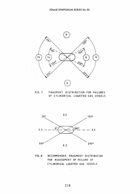
The distribution of fragments with respect to the expected preference for axial projection is examined in Fig 7. Approximately half of the fragments concerned (20 out of 39) were projected into a third of the total aTea, covered by arcs 30° to either side of the vessel front and rear axial directions. This tendency for axial projection is linked to the formation of end-tub fragments. In this analysis, if a fragment has been projected axially, that axial direction has been set at 0°. In some cases fragments will also have been projected in the opposite axial direction, ie 180°. Quite commonly only one such fragment is formed rather than two, as indicated by the greater number of fragments projected into the 0° axial zone compared to the 180° zone (14 to 6). However, in an assessment it will generally not be possible to predict which end of the vessel is likely to form an end-tub. The recommended fragment distribution for assessment purposes is illustrated in Fig 8. It is simply based on the observation that about 60% of fragments have fallen into the axial zone areas described by 60° arcs at either vessel ends, with equal likelihood of projection into either zone: ie probability 0.3 per fragment projected. The remaining 40% of fragments fall into the larger side-on zones and an equal probability of 0.2 per fragment is assumed for each of these zones.
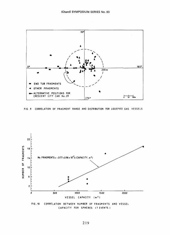
The correlation between fragment type, range and distribution is shown in Fig 9. This reveals that, as expected, end tub fragments do tend to be projected axially and do tend to travel further, only one non-end tub fragment in this limited sample being projected further than 200m. End tubs are frequently projected in directions close to, rather than precisely, axial. This is possibly due to forces acting on the vessel as it ruptures. A good example of this, for which there is some confidence in the data, is the LPG storage vessel BLEVE at Mountainville, New York in 1974 (17).
SPHERICAL LIQUEFIED GAS VESSEL DATA
Number of Fragments
Data has been obtained on seven LPG sphere failures, all BLEVEs. This -. not include the recent incident at Mexico City in November 1984 where at
211
IChemE SYMPOSIUM SERIES No. 93
least one sphere appears to have ruptured, projecting fragments. (A large number of cylindrical vessels also failed. The projection of an end tub 1km (18) is not included in the data reviewed earlier, although it is entirely consistent with that information).
The number of fragments projected in the 7 events were 3, 4, 5, 5, 6, 16 and 19 giving a mean number per event of 8.3. This is clearly very different from the data for cylindrical vessels, with a preponderance of events projecting more than 4 fragments.
Fig 10 indicates a trend that larger vessels produce more fragments. A 'least squares' straight line has been fitted to this data. Only tentative conclusions should be drawn from this limited data, however, since there are essential differences in the sample which may be important to the number of fragments produced (and their range). In addition, it is evident that the general trend is only established by virtue of two events, representing the largest vessels in the sample. Nevertheless, there is some evidence to support a hypothesis that the number of fragments projected is greater from larger vessels (unlike cylinders).
Range of fragments
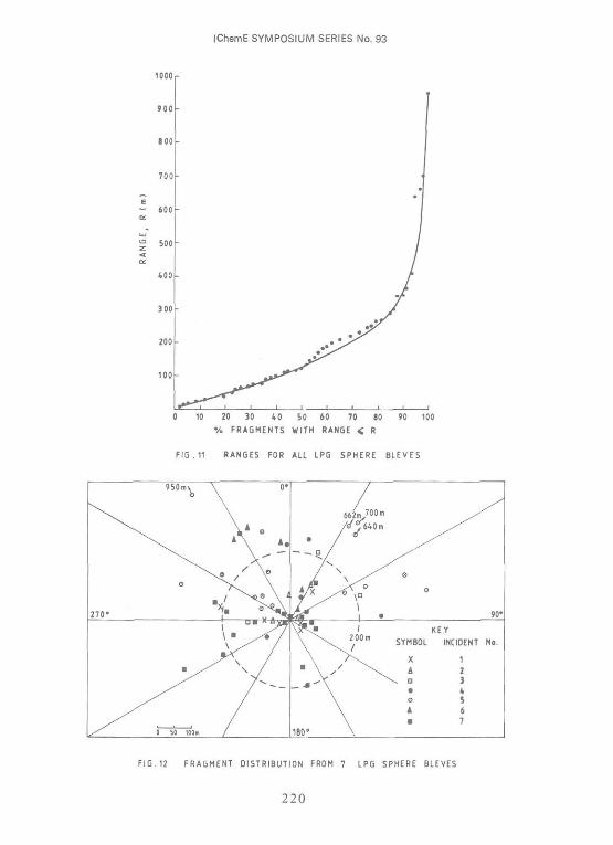
The range against cumulative percentage of the 58 fragments from the 7 events has been plotted in Fig 11. Two-thirds of the fragments travelled less than 200m. The range data is similar to that obtained for LPG cylindrical vessels in Fig 2, with the sphere fragment range being marginally higher.
Fragment Directional Distribution
The directional distribution of the fragments has been examined for all the catastrophic sphere failures considered. It has been observed that the directional distribution is non-uniform in most cases, there being a favoured direction about which most of the fragments are distributed. This is illustrated in Fig 12 and is particularly striking in incident 5. A possible explanation for this is associated with the nature of the flame impingement and the failure initiation. As cracking propagates away from the point of failure initiation, expulsion of the LPG from the sphere may lead to a general fragment directional distribution essentially opposite to the point of failure.
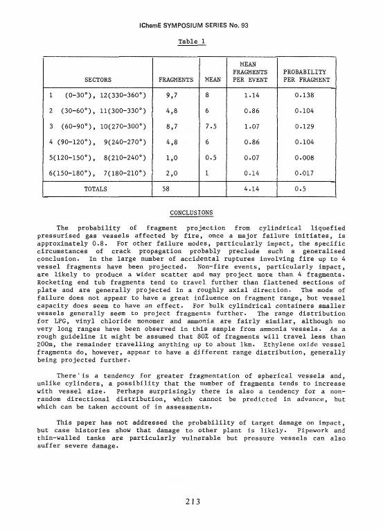
In this analysis, for each of the incidents a mean fragment direction has been estimated, the direction of this line which is into the generally favoured projection area was set arbitrarily to 0°. Fig 12 shows the number of fragments projected into 30° sectors for each of the 7 events. It may be reasonably assumed that, with sufficient data, the distribution would be symmetrical about the 0-180° axis, giving the following mean number of fragments per sector (Table 1).
A fragment is 17 times more likely to be projected into the most favoured sectors (1,12) than the least favoured (5,8). However, the distribution in sectors 9-12 and 1-4 is fairly even. Unless there is a particular reason to favour a certain direction of projection, it is recommended that random distribution should be assumed, giving a probability of a fragment landing in any 30° sector of 0.083. This could be regarded as a "best estimate" if the mean number of fragments projected (about 8) is also used. A judgemental upper bound "confidence limit" might be obtained by taking twice the mean number of fragments (ie 16) and assuming that the target is in one of the favoured sectors. This degree of sophistication cannot generally be justified missile assessments.
212
IChemE SYMPOSIUM SERIES No. 93
Table 1
SECTORS
1 (0-30°), 12(330-360°)
2 (30-60°), 11(300-330°)
3 (60-90°), 10(270-300°)
4 (90-120°), 9(240-270°)
5(120-150°), 8(210-240°)
6(150-180°), 7(180-210°)
TOTALS
FRAGMENTS
9,7
4,8
8,7
4,8
1,0
2,0
58
MEAN
8
6
7.5
6
0.5
1
MEAN FRAGMENTS PER EVENT
1.14
0.86
1.07
0.86
0.07
0.14
4.14
PROBABILITY PER FRAGMENT
0.138
0.104
0.129
0.104
0.008
0.017
0.5
CONCLUSIONS
The probability of fragment projection from cylindrical liquefied pressurised gas vessels affected by fire, once a major failure initiates, is approximately 0.8. For other failure modes, particularly impact, the specific circumstances of crack propagation probably preclude such a generalised conclusion. In the large number of accidental ruptures involving fire up to 4 vessel fragments have been projected. Non-fire events, particularly impact, are likely to produce a wider scatter and may project more than 4 fragments. Rocketing end tub fragments tend to travel further than flattened sections of plate and are generally projected in a roughly axial direction. The mode of failure does not appear to have a great influence on fragment range, but vessel capacity does seem to have an effect. For bulk cylindrical containers smaller vessels generally seem to project fragments further. The range distribution for LPG, vinyl chloride monomer and ammonia are fairly similar, although no very long ranges have been observed in this sample from ammonia vessels. As a rough guideline it might be assumed that 80% of fragments will travel less than 200m, the remainder travelling anything up to about 1km. Ethylene oxide vessel fragments do, however, appear to have a different range distribution, generally being projected further.
There"is a tendency for greater fragmentation of spherical vessels and, unlike cylinders, a possibility that the number of fragments tends to increase with vessel size. Perhaps surprisingly there is also a tendency for a non-random directional distribution, which cannot be predicted in advance, but which can be taken account of In assessments.
This paper has not addressed the probabililty of target damage on impact, but case histories show that damage to other plant is likely. Pipework and thin-walled tanks are particularly vulnerable but pressure vessels can also suffer severe damage.
213
IChemE SYMPOSIUM SERIES No. 93
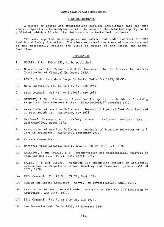
ACKNOWLEDGEMENTS
A number of people and organisations supplied unpublished data for this study. Specific acknowledgements will be made in the detailed report, to be published, which will also list information on individual incidents.
The work reported in this paper was carried out under contract for the Health and Safety Executive. The views expressed are those of the authors and do not necessarily reflect the views or policy of the Health and Safety Executive.
REFERENCES
1. HOLDEN, P L . SRD R 351, to be published.
2. Nomenclature for Hazard and Risk Assessment in the Process Industries. Institution of Chemical Engineers 1985.
3. LEWIS, D J. Hazardous Cargo Bulletin, Vol 4 Oct 1983, 34-35.
4. NFPA Quarterly, Vol 53 No 2 89-97, Oct 1959.
5. Fire Command! Vol 41, No 5 14-17, May 1974.
6. SIEWART, R D. Evacuation Areas for Transportation Accidents Involving Propellant Tank Pressure Bursts. NASA-TM-X-68277 November 1972.
7. Association of American Railroads. Summary of Ruptured Tank Cars Involved in Past Accidents. AAR R-130, May 1973.
8. National Transportation Safety Board. Railroad Accident Report NTSB-RAR-72-2, March 1972.
9. Association of American Railroads. Analysis of Fracture Behaviour of Tank Cars in Accidents. AAR-R-143, September 1972.
10. Private Communication.
11. National Transportation Safety Board. PB 190 208, Oct 1969.
12. ANDERSON, C and NORRIS, E B. Fragmentation and Metallurgical Analysis of Tank Car Rax 201. PB 241 254, April 1974.
13. BAKER, W E and others. Workbook for Estimating Effects of Accidental Explosions in Propellant Ground Handling and Transport Systems NASA CR 3023, 1978.
14. Fire Command! Vol 43 No 9 24-26, Sept 1976.
15. Health and Safety Executive. Canvey, an investigation. HMSO, 1978.
16. Association of American Railroads. Analysis of Tank Car Tub Rocketing in Accidents. AAR R146, 1972.
17. Fire Command! Vol 41 No 8 34-35, Aug 1974.
18. New Scientist Vol 104 No 1432, 29 November 1984.
214
IChemE SYMPOSIUM SERIES No. 93
215
IChemE SYMPOSIUM SERIES No. 93
216
IChemE SYMPOSIUM SERIES No. 93
217
IChemE SYMPOSIUM SERIES No. 93
FIG.8 RECOMMENDED FRAGMENT DISTRIBUTION
FOR ASSESSMENT OF FAILURE OF
CYLINDRICAL LIQUEFIED GAS VESSELS
218
IChemE SYMPOSIUM SERIES No. 93
F I G . 9 CORRELATION OF FRAGMENT RANGE AND DISTRIBUTION FOR LIQUEFIED GAS VESSELS
F I G . 1 0 CORRELATION BETWEEN NUMBER OF FRAGMENTS AND VESSEL