This Frankenstein Laser Cutter was built out of an old scanner and printer.The whole thing evolved around the instructable of Groover and his 'Pocket Laser Engraver'.This is a Making-Of. Although a lot, if not everything, of the mechnical construction requires ingenuity Itried to document the complete build process as much as I could. Every scanner and printer mechanicsare different so this could not be used as a step-by-step guide. More of a "how it can be done"-guide. Itry to cover the questions that could arise in the process of making.
I had absolutely no clue about electronics. All I knew was that RED is (often) + and BLACK is (often)Ground.
Therefore I have learned a lot in this project. Starting from mechanical stuff like self-replenishing brassbearings to electronical stuff like stepper motors and the difference between bi- and unipolar motors tosoldering and etching my own board.
The work area is 270mm x 200mm. Just about right do cut some flip-flops for the summer.
It is able to cut :foam rubbertapevinylpaper (nearly every color but white/red)several plastics (could require several runs depending on thickness)
It can engrave:light wood (Balsawood/Poplar)leatherbonehornplasticssome varnishesblank cds/dvds (purple/blue)
The color is quite important. White and in general bright colors are hard if not impossible to work with.Those colors reflect the red laser beam to much. Red(ish) colors are a problem as well as they reflect all light in the red range spectrum.
The building costs (without mispurchase [easydriver clones were for the trash can]) is around 45-55 €.
Arduino(clone) 10 €Easydriver x 2 20 €Electronic bits and pieces 10-15€Aixiz housing /w lens 6 €Alu-profiles 5 €------------------------------------- ----------Total 46-56€
Well I forgot the Laser Safety Glasses (THIS IS A MUST!!):
Build time with knowledge acquisition and waiting for shipping was around 4 month...I am constantly updating this so be sure to come back from time to time for further improvements.
UPDATES:May, 9th 2013 : Updated Step 14 : The Laser diode (pictures and some focus hints)May, 13th 2013 : Added Step 17 - Links and files section Added Step 18 - Take it to the next step (Improvement - optional) Updated BOM list. Now contains more stuff you needMay, 20th 2013 : Corrected mm/sec to mm/min ! Seconds would be very very fast.June, 1st 2013 : Added Step 13 - Alternate laser driver shield (Easylaser Shield)
Before you go an a salvage rampage consider the following hints:
RULES OF THUMBThe older the printer the better.The newer the scanners the better.
Scanner stepper motors are often superior to printer steppers. They do have more steps in general.
The newer the printer, the lesser is the chance of getting steppers out of it. All scanners have stepper motors. The older the more likely you are getting a unipolar stepper which wecan't use in this project.
--------------------------------
Identifing the parts of old devices is often a pain but I had luck with at least the scanner stepper. For theprinter I had found a service manual. But this didn't helped me alot.
Scanner / X-AxisThe scanner is an old Tevion 2400 dpi scanner. Equivalent to a Microtek Scanmaker 5800.The stepper is a 96 step bipolar stepper motor. It's description is NEOCENE 2T354207.Do not believe anyone other that says this is a 100 step motor. It is not ! It has 96 steps. Not more notless.
I used the bed of the scanner as the basis of the whole construction.The rail and the timing belt aswell as the sled which carried the photoelectronics is used.Though the sled needed to be trimmed to give more space for the laser.There is something special about the stepper. It has a 4 gears mounted on its foreplate.The gear ratio is luckly negligible.If you are still curious how to calculate a gear ratio have a look at this page (http://www.zellix.de/schritt.htm).It is in german but the math shown there is a universal language (or use the google translator)The scanner stepper serves as the x-axis.
Printer / Y-AxisThe printer was an old Epson Stylus Photo 925.The stepper I salvaged is oddly described in the Service Manual.It says it is a 4-phase 48 pole bipolar stepper motor for 42V (??) but as it is a bipolar stepper there
must not be 4 phases but 2.Turning the shaft by hand and counting the steps I came up with 48 steps.This motor (and plates for printer head) serves as the y-axis.In the end I realized that the 48 steps or the motor itself are the weak spot in this built. It moves slowerthan the scanner stepper and clatters on the rod. No brass fittings here. Vaseline should dampen thenegative effect.
Later in the process I found out that both motors draw less then at least 300 mA.The Easydriver V4.4 still has the bug with the silk print on it mixing MAX and MIN of the poti.So in V4.4 they switched the print on the PCB but simultaneously replaced the poti with a reverse poti.At least this is what I have read in some forums or the comments over at Sparkfun. Smart :)
So long story short:The poti is set to a low resistance that means the steppers get a fraction of the current the Easydrivercan deliver. Max 750mA per coil. The poti is set to roughly 25%. Just so that they dont scream in pain.
Stepper motor pinout:
On my journey through the endless deepth of the internets I often stumbled over question as how to getthe correct pinout from the steppers. You just need to take a piece of wire and connect the pins. If you connect the correct pairs you shouldfeel a resistance when turning the shaft of the stepperist
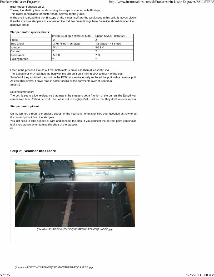
As I guess you don't have the exact same old scanner and printer this step is more like a rough lineoutof what needs to be done and what must be cared for in special. Different scanner or printers havedifferent mechanics but all in all they have similar structure.I reused the bed of the scanner and its slide that contained the photo-electronics. All the electronics andglass mirrors where removed. Use a screwdriver and wear protective gloves.
So in the end just the bare plastic remained and afterwards was cut into form to have a slightly widerspace for the printer head carriage which later carries the laser module with fan.
This was the most tedious step in the whole project. Took me about complete 8 hours to complete withthe help of an advanced craftsman (Father).
The plate of the printer which supported the print head and rod was excessively treated with my belovedmetal saw.I had to cut out pieces of the L-profile to get room for the stepper.
In the original printer structure there was a DC motor where now the stepper resides. Often (hopefully)the washer of the stepper, which is from the same printer, has the same spacing so it fitted nicely intothe DC hole.
Step 4: Printer mayhem #2
The rod on which the led the print head carrier had some decentered metal nobs on it. They could weeasily removed by twisting them and pulling them off with a plier. They revealed very nicely centeredmetal tips.
I used two T-profiles and drilled holes in them. So I could just plug the tips from both end through and
mount both profiles on the L-profile. This step needs to be precise as possible as later on the y-axismight drift off. This might distort the whole drawing/lasering process as the Y-axis isn't right-angled to theX-axis. Use a caliper is a must. Drawing by eye, too.
Step 5: Cabeling #1
Y-axis cables
As the motor moves with the Y-axis (obviously) I had to think about how to do the cabeling.I used an salvaged 5-pin connector from an old mainboard and simply soldered it to the stepper motorwires. A 4-pin ribbon cable served as an extension to a little piece of stripboard which I mounted to theL-profile.The stripboard is a "gateway" for all electronics on the movable Y-axis to the arduino.I took the flat cable which used to be connected to the scanner sledge and soldered some female pinheaders to it. Very crude job with room for improvement. If I would have been more cautious I couldhave soldered 8 pins to the flat cable but this is a very fragile task. You will see why later.
Step 6: Getting the black magic stuff on the magic black brick
To control the EDs you need to get grbl up and running on your Arduino.I used GRBL 0.8c which can be obtained from https://github.com/grbl/grbl (https://github.com/grbl/grbl)Scroll down to 'Downloads' and grab the 0.8c version. It is a precompiled hex file and can only beuploaded to the Arduino with an hex-uploader.I used http://www.ngcoders.com/downloads/arduino-hex-uploader-and-programmer/(http://www.ngcoders.com/downloads/arduino-hex-uploader-and-programmer/)
To avoid the 'out of sync' error you need to modify the baud rate at whiche the uploader sends to theArduino from 19200 to 115200. See picture.
To modify the pinout of GRBL you need to get the sources from above link and manipulate the fileconfig.h and recompile it afterwards, of course. There you are able to relocate the pins as you like. Thismight come in handy if you use another stepper driver board.To recompile type in the shell:
Before making a PCB you actually want to try out if the stuff is working as you want it to.So I put together all the electronics on a breadboard first. Only the motor part in this step.
MicrosteppingIn the top picture you can see that the Easydriver pins MS1 and MS2 are both connected to 5V. Thismeans they are "pulled high".The Easydriver is capable of doing mircostepping.Microstepping means that the steps of the motor can be devided by either 2 for half stepping, 4 forquarter and so on.
A 96 step stepper motor can do with a eighth microstepping 96 x 8 steps = 768 steps.
MS1 & MS2 - low Full steppingMS1 high Half steppingMS2 high Quarter steppingMS 1 & MS 2 high Eighth stepping
We want eighth stepping so both pins are connected to 5V.
The pinout from the Arduino is as following:
The steps/dir pins of the Easydriver are connected in the following manner:
Easydriver ArduinoX-Step Digital 2X-Dir Digital 5Y-Step Digital 3Y-Dir Digital 6
For each Easydriver the pins MS1 and MS2 are conntected and are both on 5V. This tells theEasydriver to work in 1/8 stepping mode. The Easydrivers have a seperate power supply. Any 12V600mA+ wall wart should work. Later on the shield the EDs are powered by the Arduino. As is the laserand the fan.
I took a short film from the running prototype. The Easydrivers can get quite hot. For continuouslyrunning them, a fan is required.Ehem... The fan mount is a protoype as well...
Before doing fancy stuff with the steppers they need to be calibrated. This is an essential step and mustnot be left out.I have found a nice and explanatory video tutorial over at BuildYourOwnCNC (http://buildyourcnc.com/CalibrationofLinearMotionSystemDrivenbySteppingMotors.aspx).
In generall it says you need to calculate the estimated step/mm.From that point you move your desired stepper via gcode (x200 for example). Then you need to take thediscrepancy and calculate your new step/mm until it moves the exact range you commanded. But seethe video for more information ans some math. I suggest to create an excel sheet to save you some headache.
You can use every kind of terminal tool to communicate with grbl. I used CoolTerm (http://freeware.the-meiers.org/).I guess you know how to load a terminal and connect to your Arduino.
In the picture you can see my current calibrated data.
To communicate with (and send gcode to) the Arduino and its stepper drivers there are severalsolutions.You could check the GRBL Wiki (https://github.com/grbl/grbl/wiki/Using-Grbl). Scroll down and you'll findplenty of software that deals with GRBL and Arduino.There are even some nice GUI tools. Nevertheless I used Groovers Gcodesender. Can be found onGroover's Pocket Laser Instructable (http://www.instructables.com/id/Pocket-laser-engraver/step7/Getting-the-software-ready/) (Step 7).
Go ahead and try some g-code commands.Get your steppers in the correct starting position before powering them (e.g. zero position) and type
G91 G28 X0 Y0
This tells GRBL that the current position is the zero position.X50 Y50
This moves the 'spindle' to the absolute position of X50 Y50
G01 X50 Y50this would move the spindle 50mm on the X and 50mm on the Y-axis from whatever position the spindlecurrently resides. This is the relative positioning.
For more information on gcode commands, check the wikipedia page (link (http://en.wikipedia.org/wiki/G-code)).
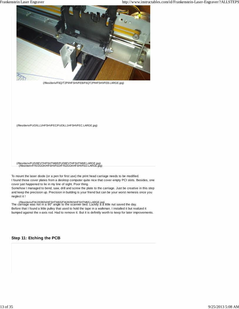
To mount the laser diode (or a pen for first use) the print head carriage needs to be modified.I found those cover plates from a desktop computer quite nice that cover empty PCI slots. Besides, onecover just happened to lie in my line of sight. Poor thing.Somehow I managed to bend, saw, drill and screw the plate to the carriage. Just be creative in this stepand keep the precision up. Precision in building is your friend but can be your worst nemesis once youneglect it !
The carriage was not in a 90° angle to the scanner bed. Luckily a a little nut saved the day.Before that I found a little pulley that used to hold the tape in a walkman. I installed it but realized itbumped against the x-axis rod. Had to remove it. But it is definitly worth to keep for later improvements.
NOTE: I added an alternate laser shield. See step 13 for information and Eagly CAD layout.
After I managed to get my prototype breadboard running successfully some sample g-code I went on tocreate a PCB.Never have done such a thing before but I am a chemical laboratory assistant and chemicals do notraise fear in me.
Again I used Groovers lasershield layout (http://www.instructables.com/id/Pocket-laser-engraver/step5/Electronics/). It comes in EagleCAD format.
I mirror printed the layout on ordinary paper and glued it to a photosensitive copper board and used mydremel clone to drill the holes. As I do not have a fancy exposure timer I took some alcohol and removedthe protective varnish.With a overhead projector pen and a ruler I traced the layout by hand. This pen gave a very nice shinytrace.I also tried to use a thin permanent marker (acid-resistant / Edding 400 in Germany) but the result was athick ugly line.Although with the overhead pen I just needed to draw the trace once and not several times to get a nicecoating.
To etch the layout I used Fe(III)Cl. Don't like the other stuff that is available. They could vaporate, theystink and stuff that contains peroxid can explode when kept in sealed bottles. So Fe(III)Cl is the mostconvenient solution to store and dispose.
Nevertheless : !! Don't pour it down the drain !! It is going eat your drainpipe if it is made fromcopper and it will definitely kill all the little usefull bacteria in your local sewage disposal facility.
I do not know how to solder the pins (that connect to the Arduino pins) from the wrong side so I justplaced them on the top side of the PCB and pushed the tips through.
To safe some time I wrote on the PCB were the parts for the laser driver should go. Side note: for testruns without laser you can leave out the circuit for the laser for now.
Partslist:
Part Value Device Package Description VR05R051 RR1A RR1A RR1A RELAYC1 0,1uF C-US075-052X106 C075-052X106 CAPACITORC2 47uF CPOL-USE2.5-5 E2,5-5 POLARIZED CAPACITOR
I have also included an exported shopping list from my electronic merchant as it is sometimes a bitdaunting looking up all the parts with different descriptions.
NOTE: I did order the wrong relay from my electronic supplier so I ripped apart an old pc power supply I found inmy electronic chest of wonderments. I am actually quite glad I keep alot of the "old stuff". Most of theelectronics are still working. I rather keep them instead of making the recycling depot happy. They sell itto Africa as "2nd-hand" which is not realy the truth. Hence I have build this laser. Show people that "the old stuff" is no junk. In the right hands it is asprecious as real money.
NOTE #2 (important):When connecting the Arduino with installed board be sure to connect the external power supply FIRST.I noticed that when connecting the Arduino to USB first with out power supply the motors start toscream. This does not sound healty. Remember the movie "Screamers" ?
The Lasershield by Groover is great but I found some things that didn't satisfied my style of operatingthe laser.
The laserhshield isn't capable of switching the microstepping modes for the stepper motors.
With DVD stepper motors he used there was no need to do so but when using different motorsfrom different devices this can help to drive those motors correct.
The relay that controlled the laser to turn on and off I wasn't very happy with, too.And lastly the wires from the drivershield to the laser diode were too long. Putting the driver next tothe laser would be better I guess.
So Tl;dr :
I redesigned the lasershield from Groover.Removed the laser driver circuit - Replaced with a terminal clamp to attach a ready made laserdriver. I got mine from AixiZ at ebay (link (http://www.ebay.com/itm/Adjustable-current-laser-diode-driver-80-500mA-w-TTL-/360668752563?pt=LH_DefaultDomain_0&hash=item53f9886ab3)).
1.
Added jumpers beneath the Easydrivers to set the microstepping mode.2.
UPDATE: Who ever first finds the error in this schematic and
The laser diode I used here is pretty strong. Aimed at 300mW this red laser is a Class 3b laser whichmeans goggles must be worn at all cost.You will get pinkeye and a cataract. It is not like with smoking were you could possible get cancer. No,looking into the beam will definitly get you a cataract. Even the scattered light the diode produces whenbouncing of surfaces is stronger then directly looking into the sun. You don't want to risk you sight.Period.
BE CAREFULL !!
The laser goggles should filter 600-670nm (OD4+). Those glasses are not cheap but your eyes areprecious !OD4+ means that it does filter 10 -4 of the incoming (red) light.Example:300 mW * 10 -4 = 0,03 mW.
Laser diode pinout:The first thing to do when having stripped the diode from an old DVD Burner or got it from the internet isto get the polarity of it.I just took 2 AA batteries that were in a case with + and - and tried the pins of the diode until it lits up.
Laser diodes of this type are placed into an aixiz housing with heatsink. They often come with afocusable plastic lens. Glass lense are better as they give you about 10-20% more efficiency.
Adjust the power of the laser diode:Before we want to hook up our laser to the circuit we want to adjust the "power" it will get.With the blue potentiometer this is easy to do.The red DVD burner diode can handle just about 300mV (respectively 300mA - with a load) but then Idon't know how long it will last.If you want to increase the lifetime you may want to reduce the voltage the laser diode gets to around200mV (respectively 200mA - with a load).Anyways keep your eyes on cheap or donated DVD burners. Sometime the local recycling plant hassome of these pearls in their trash. Kindly asking the service personal may get you fresh meat for yourlaser grinder.You don't want to adjust the power of the laser diode with the actual laser diode. Sounds strange but wewill be using a so called dummy load.A dummy load is placed in the circuit instead of the real diode. It acts as a load and you can steadilyincrease the power while measuring the voltage without damaging the precious salvage diode.In the picture above you can see such a dummy load. This one simulates a red laser diode. If you aregoing to use a blue laser you simply need 6x 1N4001 diodes.
Material: Red laser diode dummy Blue laser diode dummy
1N4001 4x 6x
1 ohm Resistor 1x 1x
Again use your breadboard and put the diodes and the resistor in series. On the resistor I measure thevoltage. It doesn't matter on which side you place the resistor. Set your multimeter to 2000mV and put itto the resistors' ends. Connect the laser pins from the lasershield to + and - on the breadboard.Load up gcodesender or your terminal of choice and connect to the Arduino.Send the command "M3" (Spindle/Laser on) and you should get some value on your multimeter.Turn the potentiometer on your potentiometer clockwise untill it reaches the desired voltage e.g. 300mV.This corresponds to the mW the laser diode will get.CW = increase voltageCCW = decrease voltageSend "M5" to turn off the laser.
Focusing the laser:To focus the diode I first turned the lens until I got a very small dot on the wall. Then I tried to light amatch.To get a "rough" focus I taped a ruler to my desk with the laser housing at 0mm.A black sheet of paper (thicker paper like 450gr photo carton) was placed in front of the laser and moveduntil it burned.You may need to play around with the lens and the paper distance.
To do the fine adjustment I proceeded similar again but this time I estimated the time it took the laser toburn a hole through the paper. This way you get very close to the perfect focus of the laser.
Defining the area:In Inkscape you need to set the dimensons of the working area. To do this hit:File - Document Propertiesand change the page to your size
One thing to know before starting the cutting mayhem.How to get g code for your models.
My weapon of choice is Inkscape with Groovers modified Gcodetools (Metalevel 8).Inkscape can be downloaded from their page (http://inkscape.org/).Groover'g gcodetool is available on his Instructable (http://www.instructables.com/id/Pocket-laser-engraver/step7/Getting-the-software-ready/).
The drawing needs to be mirrored before creating the gcode.If you just plainly select all and mirror it, it could give you a strange output inside Inkscapeso before mirroring, select all (Ctrl + a) group everything (Ctrl + g) and mirror it ('h').After it is mirrored ungroup everything (Ctrl + Shift + g) and convert everything to path again (Ctrl +Shift + c).
The gcodetools need to be copied to "...\Inkscape\share\extensions".
To get the gcode I always do these steps:1.) Ungroup all your objects (maybe need to do it twice)2.) Strg + a (select all) - Path - Object to path3.) Sill selected all -> Extensions - Laserengraver - Laser4.) Under "Preferences" insert your output folder5.) Switch back to "Laser" tab. This is important !!6.) Enter your desired speed. This can be overwrite with Groovers Gcodesender later.7.) Enter filename +.nc. Hit Apply. Done8.) Fire up gcodesender. Connect to your Arduino. Load the .nc file. Set speed if desired.9.) Put on goggles. !!!10.) Hit "Print"
He has some nice models on his website (http://elabz.com/resources/cnc-files/), too.
Here are some settings for cutting and engraving different materials:
Craft foam - 2mm - black - 75 mm/min
Balsawood - 1 mm - the dark lines were engraved with 50 and afterwards with 10 mm/min. The outerrings were drawn with 100 mm/min.
The calculator case was engraved with around 75 mm/min.
I have been a EvE player for nearly 8 years so this is my tribute. The blue sculpture is a spaceshipcalled "Caracal / Cerberus" (Copyright @ CCP Games)The model was sliced with Autodesk 123D Make Software (http://www.123dapp.com/make).
Step 17: Links and filesSoftwareArduino Hex file uploader - used to upload the grbl hex file to Arduino (link (http://www.ngcoders.com/downloads/arduino-hex-uploader-and-programmer/))
GRBL - gcode interpreter for Arduino (Atmega328 compatible) - In this tutorial version 0.8c is used (link(https://github.com/grbl/grbl)) / Wiki (https://github.com/grbl/grbl/wiki)
Inkscape - open source vector drawing tool (link (http://inkscape.org/download/?lang=en))
Gcodetools - Inkscape plugin to generate Gcode from vector drawingsmodified Groover version (easy and fast) (download (http://www.slackersdelight.com/instructables/laserengraver.zip))original Gcodetools (complex) (link (http://www.cnc-club.ru/forum/viewtopic.php?f=15&p=101))
Gcodesender - tool to send Gcode from PC to Arduino - by Groover (download (https://github.com/downloads/OttoHermansson/GcodeSender/gcodesender.exe)) / (source (https://github.com/OttoHermansson/GcodeSender))
Lasershield PCB layout - made by Groover (download (http://www.instructables.com/files/orig/FJR/6Y6Z/GKS0U2RW/FJR6Y6ZGKS0U2RW.zip))
EagleCAD - PCB layout tool - free version available (link (http://www.cadsoftusa.com/download-eagle/?lang=en))
Autodesk 123D Make - 3d model to sliced objects (link (http://www.123dapp.com/make))
TutorialsGear ratio tutorial (link (http://www.zellix.de/schritt.htm))
Stepper motor calibration video tutorial by BuildYourOwnCNC.com (link (http://buildyourcnc.com/CalibrationofLinearMotionSystemDrivenbySteppingMotors.aspx))
Laser safety
README please !!!!
Laserpointerforums.com (http://laserpointerforums.com/f53/get-some-safety-goggles-now-75799.html) -Thread about eye damages done by lasers
Step 18: Take it to the next step (Improvements - optional)
This steps are optional
Since I finished the Frankenstein Laser Engraver I did alot of engraving and made some improvementson the build. Or at least what I think could improve the whole machine.
1. Replaced working surfaceThe back of the picture frame looks nice and does not get burned to strong by the laser. But fixing work pieces requires tape. Don't get me wrong. I like tape. Especially duct tape :) but there isa better solution.I took the side panel of an old metal PC case and cut out a piece to fit on the scanner ground.Using neodynium magnets helps fixing your work piece.Especially harddrive magnets are usefull as they are strong and have a metal plate attached. I foundsome from old harddrives with 3mm and 4mm thick magents. Just perfect to hold different woodthicknesses.However if your motors are not well shielded these magnets could cause interefences with them.
2. Shielded cablesI realized that when putting the cables from the motors and the laser to close together EMC troubles canoccur.Re-lay the cables in 90° to each other (motors / laser) minimizes these troubles. Anyway I stumbled oversome old USB cables.Those are often shielded (thick ones) and have 4 wires. The diameter of the cores are not perfect butshould work okay.In the picture where the pins are soldered to the wires I left out the shrinking tubes as it was too much ofa hassle to solder the wires to the pins. I later on cut fitting shrinking tubes and sliced them on one sideand slid them over the wires.
3. Case for the hardwareI found a site (http://boxmaker.rahulbotics.com/)that offers a script to generate nice boxes that can becut out and put together using box joints. This laser is by far to weak to cut wood but it can engrave itpretty good. I hammered in the dimensions of my desired box and got the pdf to download.In Inkscape I realigned all the pieces to use the space more efficiently.With a fine wood saw I sawed the vertical lines and used a jigsaw to do the horizantal lines.I drilled some holes for ventilation and the cables and put a small PC (southbridge) fan on top of it.One thing is important. The fan might cause interferences with the Easydrivers so they could loosesteps or stop in the middle of the process. It is therefore important to place the fan in a secure distanceto the motor drivers.
4. Laser diode replacementTypically laser diodes found in DVD burners are Small Closed Can-Types. Those should not exceed acurrent of 300mA.I have found some interesting threads over at Laserpointerforums.com that talk about cheap red laserdiodes.So a good alternative would be the LPC 826 red laser diode. It can be nicley driven at around 300mA.Combined with a glass lense which delivers more optical power to the work piece would be a greatimprovement. Those laser diodes are 11$ / 8,50€ (free shipping) and might be worth it.(eBay link to LPC 826 diodes (http://www.ebay.de/itm/MITSUBISHI-658nm-660nm-300-400mw-CW-Red-Laser-Diode-LPC-826-/110896818957?pt=US_Stage_Lighting_Parts_Accessories&hash=item19d1f72b0d#ht_914wt_952))
1-40 of116
Next » (http://www.instructables.com/id/Frankenstein-Laser-Engraver/?&sort=ACTIVE&limit=40&offset=40#DISCUSS)
elabz (/member/elabz/) says:
Nice project! The scanner base gives a very nice area to work with. I've dabbled with DVD-RWbased laser engravers/cutters (a lot) and their 1.5"x1.5" (38mm x 38mm) workarea is quite alimitation - I'm sure having 270mm x 200mm is quite liberating!What are the accuracies you are getting with this setup (96SPR + pulley) - what diameter is thedriving pulley and how close are you able to get to the max resolution with EasyDriver?
ianmcmill (/member/ianmcmill/) (author) in reply to elabz
Having such a big work area isreally quite nice !
I am getting an accuracy of1/10mm (0,0039"). The x-axisdriving pully (scanner) is 9,1mm indiameter(0,358"). The y-axis pullyhas 6,4mm diameter.
For the resolution, the scanner stepper with 96 steps does very well with 1/8 stepping. Theprinter stepper is running in 1/8 stepping as well but as it moves the motor doesn't soundvery "clean". Actually it has a nice accurarcy of 1/10mm, too. But 1/4 stepping would bebetter I think. Another option would be to replace the stepper with another, bigger (innumber of steps) stepper motor but I havn't found any good replacement (slavage) by now.I am learning something new everyday and things get clearer the more I read and try.
elabz (/member/elabz/) in reply to ianmcmill
I'm coming up with (9.1mm x3.1415)/96 = ~0.29mm as the maxresolution for the scanner motorwith 9.1mm pulley in full step mode.I am curious if you're able toincrease that by using 1/8thmicrosteps. Did you measure0.1mm?
I've done such measurement beforeby cutting a line at a very acuteangle. Say, you want to cut a linealong the Y axis but have the X atthe beginning to be 1mm off from Xat the end. Doesn't matter, 1mmmore or 1mm less, just has to beoff. The longer the line the easier itwill be to see the accuracy. Onceyou cut the line, you should be ableto see quite clearly 10 saw-toothlike regions that break the straightline (hold it toward a light source tosee easier) if your accuracy is0.1mm, 5 teeth if you accuracy is0.2mm, 4 teeth if 0.25mm and soon.
I've done it for DVD-RW stepperswith the stock 3mm pitch leadscrew which in theory should have0.15mm resolution (3mm/20SPR = 0.15mm per step) and I cannot seeany improvement whatsoever in anyof the microstepping modes. I'vealso played with the current settingof the EasyDriver - nothing I didcould create any better resolutionthan what's available in full stepmode. I chucked it up to mystepper being overloaded. I wonderif you get any different results fromyours.
By the way, I actually found0.15mm accuracy to be quite badfor my tiny cutter. The details Iwould want to cut were so smallthat I needed them to be extremelyaccurate and 0.15mm just didn't cutit (pardon the pun). See if you cancut yourself a tiny 1:212 scale model of Lockheed P-38J Lightning(http://elabz.com/resources/cnc-files/) from here out of 3mmcraft foam - it only holds togetherwithout glue if the accuracy isbetter than approx 0.05mm. Samewith the tiny rocket model there - ifit holds together, it's at about themaximum resolution that you canget from this laser cutter. It will bereally difficult to focus the laserinto a spot less than 50 micronanyway.
ianmcmill (/member/ianmcmill/) (author) in reply to elabz
Okay trying this one but I think theprinter stepper is the crucial pointor it's microstepping mode. I didthe rocket you coded on your pageand I needed some glue to hold ittogether.
you should be able to see quiteclearly 10 saw-tooth likeregions that break the straightline (hold it toward a lightsource to see easier) if youraccuracy is 0.1mm, 5 teeth ifyou accuracy is 0.2mm, 4 teethif 0.25mm and so on.
You mean like "M3 X100 Y100".Cutting a diagonal line ?
ianmcmill (/member/ianmcmill/) (author) in reply to ianmcmill
(9.1mm x 3.1415)/96 = ~0.29mmas the max resolution
Ah okay now I understand whatyou mean by 'max resolution'.The more I think about it, themore my "measured" accuracycracks. I measured it with a rulerthat has 0.5 mm steps (0,01968inches) and I just estimated this0.1mm.
elabz (/member/elabz/) in reply to ianmcmill
M3G1 X1 Y100M4
I think this would be the right Gcodeas interpreted by Grubl (if M3 turnsthe laser on, M4 off). In otherwords, the X travel should beminimal, ideally 1 mm.
I don't know idiosyncrasies ofGrubl's processing of the Gcode.Perhaps the construct you gave willwork but even then it would read asM3 X1 Y100
ianmcmill (/member/ianmcmill/) (author) in reply to elabz
I had a chat with elabz andhere is the result of hisGcode from abovehttp://imgur.com/ehNSXsP
Top lines show theaccuracy of the Y-axis.Bottom, that of the x-axis.The x-axis is pretty clean sofar. But the y-axis lacksaccuracy for now. Switchingthe stepping mode couldhelp. Or some dumpsterdiving.
ianmcmill (/member/ianmcmill/) (author) in reply to ianmcmill
Hi Ian, thanks again for your answer! Your support is very helpful :)
I've found the source of the problem. When installing laserengraver from groover, this overwritesdxf_input.inx. So I reinstalled inkscape to get the original back.Then, the z-depth in the orientation tools was not set correctly. I used 0, so it would not try to usethe z-axis. But this resulted in the empty gcode files. So, I think this was the source of the problems.
But now before it makes the lines it tries to move the z-axis which is not there. Is there a way tostop it from doing this? The problem is that it already cuts when it should not. I'm engraving mirroredplexiglass so it is very sensitive to being burned too long.
Do you have a solution to this?
Thanks!
ianmcmill (/member/ianmcmill/) (author) in reply to fritzerik
The problem with cutting when itshould not came up here as well.Only after I installed the bought laserdriver from aixiz this problem wassolved. I really don't know why theoriginal laser driver from Groover hadthis problem but I could imagine thatthe relay could be the cause. But I amjust guessing.
As for the z-axis. You could try toincrease the z-axis speed in GRBLsettings to something very high like5000 and at the same time set thez-depth in gcodetools to 0.1 orsomething > 0. Anyways always dotest runs on non-critical material likecardboard.
Engraving on mirrored plexiglasssounds interesting. I wonder if the redlaser is capable of engraving it at all.
fritzerik (/member/fritzerik/) in reply to ianmcmill
Sorry for thelate reply. I'vebeen busystudying...anyways.I solved theproblem that Ihad by usingnotepad andsearch/replaceto removeeverything thatincorporates az-axis. Thisworks verygood.But, I get somestrangebehaviour frominkscape. WhenI convert theimage to areafilling, zig/zag,then it does notfill the blackareascompletely andI get somestrange linesthat do notcorrespond tothe lines thatshould be (seeimage).It seems as ifthe angle atwhich the zigzaggoes (in thiscase 45 deg)gives problemsat the objecthaving 45 degparts.
Have you everencounteredsomething likethis? Would youhave an ideawhat might bethe problemhere?
ianmcmill (/member/ianmcmill/) (author) in reply to jduffy54
The Arduino or let's say GRBL on theArduino sends an ON/OFF signal viadigital pin 12 to the laser driver. Thisis called a TTL signal. The driverswitches the laser diode on or off.
dbrummett (/member/dbrummett/) says:
So could this cut through gasket material to create custom gaskets for engine parts? :) I really likethis idea and I'd also like to ask where I could find a higher powered laser and what power to lookfor?
ianmcmill (/member/ianmcmill/) (author) in reply to dbrummett
I think it could cut into gasketmaterial but it depends on thethickness. But cutting though gasketin one pass could be hard. I tried tocut a black CD case and it took 4-5passes to cut it. With that manyruns the borders were not cut sharpbut melted. More power is alwaysbetter :). A more efficient methodwould cleary be blue laser but thesedrastically increase the costs. Idon't know how much power youneed to cut gasket or 1mm plasticin one pass. There are 1-2 wattblue laser diodes available.Someone(http://laserpointerforums.com/f64/dtr-s-laser-shop-1-5w-2w-m140-diodes-45-shipped-us-61635.html)fromlaserpointerforums.com sells them.There is a 2 Watt version of theM140 diode that comes completewith all you need. Driver, housing(incl. copper module for bettercooling, glass lens) for 125 $. Thisis the most complete kit I have seenso far. An extra cooling fan isrequired ! Some people even addPeltier elements to cool it. And notto forget the protection glass for awavelength of 445nm.
All in all, I really would like to getmy hands on such a diode. All thatis keeping me back is the price.Before I would attach such amonster to my F.L.E. I wouldcompletely rebuild it with of theshelf 200step stepper motors formore precision.
Typpa (/member/Typpa/) says:
Hi, today i cannibalise Two HP :-) ... The motor is 2 way ? :-( ... The fan work at 5v .... My oldArduino i DEAD , today i buy new Arduino :-) ...
ianmcmill (/member/ianmcmill/) (author) in reply to Typpa
The cooling fan build looks verynice :) No more problems with heatanymore.The motors on the printer are DCmotors. You cannot use them. Youneed stepper motors. Bipolarstepper motors to be exact. Thosehave 4 wires.The rods and carriages are nice.
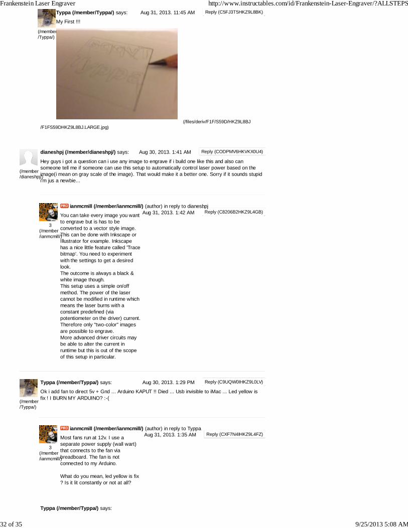
Hey guys i got a question can i use any image to engrave if i build one like this and also cansomeone tell me if someone can use this setup to automatically control laser power based on theimage(i mean on gray scale of the image). That would make it a better one. Sorry if it sounds stupidi'm jus a newbie...
ianmcmill (/member/ianmcmill/) (author) in reply to dianeshpj
You can take every image you wantto engrave but is has to beconverted to a vector style image.This can be done with Inkscape orIllustrator for example. Inkscapehas a nice little feature called 'Tracebitmap'. You need to experimentwith the settings to get a desiredlook.The outcome is always a black &white image though.This setup uses a simple on/offmethod. The power of the lasercannot be modified in runtime whichmeans the laser burns with aconstant predefined (viapotentiometer on the driver) current.Therefore only "two-color" imagesare possible to engrave.More advanced driver circuits maybe able to alter the current inruntime but this is out of the scopeof this setup in particular.
Typpa (/member/Typpa/) says:
Ok i add fan to direct 5v + Gnd ... Arduino KAPUT !! Died ... Usb invisible to iMac ... Led yellow isfix ! I BURN MY ARDUINO? :-(
ianmcmill (/member/ianmcmill/) (author) in reply to Typpa
Most fans run at 12v. I use aseparate power supply (wall wart)that connects to the fan viabreadboard. The fan is notconnected to my Arduino.
What do you mean, led yellow is fix? Is it lit constantly or not at all?
Hi Ian ... Little problem...After 3/4 min thecommunication USB/arduino is down.. And thesystem is KO . Why?very hot easy drive? Isgood idea use dissipatorfor easy drive... Sorry formy bad English
ianmcmill (/member/ianmcmill/) (author) in reply to Typpa
Hi. So the easydrivers have athermal shut down that preventsthem from overheating. This couldexplain the communicationproblem. Try to add a small heatsink and a small fan to it. I justplaced a left over fan next to theeasydrivers.No problem with your english.Meaning over form is the key.Keep on writing and reading aboutstuff that interests you and this willimprove.
Typpa (/member/Typpa/) says:
Hi ianThis laser ?http://www.aixiz.com/store/product_info.php/cPath/48/products_id/235
ianmcmill (/member/ianmcmill/) (author) in reply to Typpa
This is a closed can laser diodelike the one you find in a DVDwriter. I replaced my DVD diodewith a LPC diode. Long Open Can.Those diodes can take morecurrent and are currently yourweapon of choice when it comes tocutting/engraving with a red laserdiode. I personally would go withthis one LOC red laser(http://odicforce.com/shop/article_OFL314/LPC-826-658nm-Red-Laser-Diode-250mW%2B.html?sessid=RUPlAyjPgPjx97dpP2uYpahpSa0shop_param=cid%3D35%26aid%3DOFL314%26It is much cheaper and as far asthe laserpointerforums.com say,the better choice over the one youposted.
ianmcmill (/member/ianmcmill/) (author) in reply to ianmcmill
I have found a nice picture ofthose two types of diodes in thelaserpointerforums.com(http://laserpointerforums.com)forum.
From left to right: Closed can /Closed can / Long open can
Forum link of a Pioneer blu-ray writer disassembly. (http://laserpointerforums.com/f38/bdxl-pioneer-bdr-206m-63328.html)
Typpa (/member/Typpa/) says:
The best diode laser from aixiz.com ? Or is the same on DVR - R recycled
ianmcmill (/member/ianmcmill/) (author) in reply to Typpa
DVD-R diodes can do 300mW butwill die sooner.
This one is more capable of driving300mW:http://www.ebay.de/itm/MITSUBISHI-658nm-660nm-300-400mw-CW-Red-Laser-Diode-LPC-826-/110896818957?pt=US_Stage_Lighting_Parts_Accessorieshash=item19d1f72b0d#ht_914wt_952
See step 18(http://www.instructables.com/id/Frankenstein-Laser-Engraver/step18/Take-it-to-the-next-step-Improvements-optional/) formore information.
ianmcmill (/member/ianmcmill/) (author) in reply to Typpa
Nice build ! Groover-style
Typpa (/member/Typpa/) says:
Hi from Italy... Very good DIY Laser. 3 days for assenble and set on OSX 10.8 ..one question abouttheAdjustable current laser diode driver 80-500mA w/TTL[AIX-RBD] form Aixiz.comIs good driver ?
ianmcmill (/member/ianmcmill/) (author) in reply to Typpa
ianmcmill (/member/ianmcmill/) (author) in reply to Typpa
Yeah I am quite satisfied with it.Works good.
1-40 of116
Next » (http://www.instructables.com/id/Frankenstein-Laser-Engraver/?&sort=ACTIVE&limit=40&offset=40#DISCUSS)
About Us
Who We Are (/about/)Advertise (/advertise/)Contact (/about/contact.jsp)Jobs (/community?categoryGroup=marketplace&category=jobs_internships)Help (/community?categoryGroup=Help)
Terms of service (/tos.html) | Privacy ((http://m.instructables.com)
2013 Autodesk Inc. All rights reserved (http://usa.autodesk.com/adsk/servlet/pc/index?id=20781545&siteID=123112)http://usa.autodesk.com/privacy/) | Legal Notices & Trademarks (http://usa.autodesk.com/legal-notices-trademarks/) | Mobile Site