JOURNAL OF SOUND AND VIBRATION Journal of Sound and Vibration 310 (2008) 91–109 Free vibration of higher-order sandwich and composite arches, Part I: Formulation Sudhakar R. Marur a, , Tarun Kant b a CSS Foundation, 313, A4 Wing, Cauvery Block, NGH Complex, Koramangala, Bangalore 560047, India b Department of Civil Engineering, Indian Institute of Technology, Powai, Mumbai 400076, India Accepted 28 July 2007 The peer review of this article was organised by the Guest Editor Available online 23 October 2007 Abstract A higher-order refined model with seven degrees of freedom per node is presented in this paper for the free vibration analysis of composite and sandwich arches. The strain field is modeled through cubic axial, cubic transverse shear and linear transverse normal strain components. As the cross-sectional warping is accurately modeled by this theory, it does not require any shear correction factor. The stress–strain relationship is derived from an orthotropic lamina in a three- dimensional state of stress. The proposed higher-order formulation is validated, in this first part, through arches with various curvatures, aspect ratios, boundary conditions and materials. r 2007 Elsevier Ltd. All rights reserved. 1. Introduction Laminated composite and sandwich arches or curved beams are being used in various automotive, aero space, energy, medical and sports applications, to name a few, due to their high strength to weight ratio. Developing predictive capabilities to assess their vibration characteristics, a priori, is a key aspect of design of components with such materials. Ahmed [1] evaluated the vibration characteristics of curved sandwich beams using finite elements with three to five degrees of freedom per node. He studied effects of factors such as core–face density ratio, core rigidity, core–face thickness and subtended angle on the arch frequency. Similarly, Petyt and Fleischer [2] adopted finite element models for the radial vibrations of a curved beam. They ascertained the role of subtended angle on the frequencies, for various end conditions. Veletsos et al. [3] studied the free vibrations of circular arches in their own plane and their mode shapes, through an iterative numerical procedure. Based on the modal and strain energy distribution patterns, they classified modes as flexural, axial or coupled. They extended their study later [4] by including rotatory inertia and shear deformation. ARTICLE IN PRESS www.elsevier.com/locate/jsvi 0022-460X/$ - see front matter r 2007 Elsevier Ltd. All rights reserved. doi:10.1016/j.jsv.2007.07.084 Corresponding author. E-mail addresses: [email protected] (S.R. Marur), [email protected] (T. Kant).
Transcript
ARTICLE IN PRESS
JOURNAL OFSOUND ANDVIBRATION
0022-460X/$ - s
doi:10.1016/j.js
�CorrespondE-mail addr
Journal of Sound and Vibration 310 (2008) 91–109
www.elsevier.com/locate/jsvi
Free vibration of higher-order sandwich and composite arches,Part I: Formulation
Sudhakar R. Marura,�, Tarun Kantb
aCSS Foundation, 313, A4 Wing, Cauvery Block, NGH Complex, Koramangala, Bangalore 560047, IndiabDepartment of Civil Engineering, Indian Institute of Technology, Powai, Mumbai 400076, India
Accepted 28 July 2007
The peer review of this article was organised by the Guest Editor
Available online 23 October 2007
Abstract
A higher-order refined model with seven degrees of freedom per node is presented in this paper for the free vibration
analysis of composite and sandwich arches. The strain field is modeled through cubic axial, cubic transverse shear and
linear transverse normal strain components. As the cross-sectional warping is accurately modeled by this theory, it does
not require any shear correction factor. The stress–strain relationship is derived from an orthotropic lamina in a three-
dimensional state of stress. The proposed higher-order formulation is validated, in this first part, through arches with
various curvatures, aspect ratios, boundary conditions and materials.
r 2007 Elsevier Ltd. All rights reserved.
1. Introduction
Laminated composite and sandwich arches or curved beams are being used in various automotive, aerospace, energy, medical and sports applications, to name a few, due to their high strength to weight ratio.Developing predictive capabilities to assess their vibration characteristics, a priori, is a key aspect of design ofcomponents with such materials.
Ahmed [1] evaluated the vibration characteristics of curved sandwich beams using finite elements with threeto five degrees of freedom per node. He studied effects of factors such as core–face density ratio, core rigidity,core–face thickness and subtended angle on the arch frequency. Similarly, Petyt and Fleischer [2] adoptedfinite element models for the radial vibrations of a curved beam. They ascertained the role of subtended angleon the frequencies, for various end conditions. Veletsos et al. [3] studied the free vibrations of circular arches intheir own plane and their mode shapes, through an iterative numerical procedure. Based on the modal andstrain energy distribution patterns, they classified modes as flexural, axial or coupled. They extended theirstudy later [4] by including rotatory inertia and shear deformation.
ee front matter r 2007 Elsevier Ltd. All rights reserved.
ARTICLE IN PRESSS.R. Marur, T. Kant / Journal of Sound and Vibration 310 (2008) 91–10992
Singh and Singh [5] studied the in plane vibrations of rotating rings and sectors, with shear deformationthrough finite element method. Balasubramanian and Prathap [6] explored the locking and field-consistencyaspects of a shear flexible curved beam element for the vibration of stepped arches.
Heppler [7] developed Timoshenko beam elements, using trigonometric basis functions, for studying thevibration of curved beams. Qatu [8,9] developed an exact as well as Ritz method-based approximate solutionsfor the vibration of laminated composite arches. His book [10] elaborates the theoretical basis of compositearch vibrations, in detail.
Auciello and De Rosa [11] studied the vibrations of classical arches through Galerkin, Ritz and finiteelement methods. They examined the influence of cross-sectional variations and of flexible supports on thevibration of arches. Krishnan and Suresh [12] developed a cubic element to study the effects of curvature,shear deformation and rotary inertia on the fundamental frequency of curved beams. Krishnan et al. [13]explored the role of subtended angle on the fundamental frequency of arches, with various end conditions.Sakiyama et al. [14] studied the free vibrations of sandwich arches with elastic or visco elastic core, variousaxis shapes and end conditions, through Green functions. Tseng et al. [15,16] studied the vibrations of first-order shear deformable arches with variable curvature, using dynamic stiffness method. Kang et al. [17,18]studied the vibrations of shear deformable circular arches using differential quadrature method. Many authors[19–22] explored the influence of axial extension, rotatory inertia and shear deformation on the vibrations ofarches, in the past.
Khdeir and Reddy [23] developed a third-order theory for the vibration studies of shallow composite arches.Raveendranath et al. studied the performance of a curved beam element with coupled polynomialdistributions [24] and also developed a two-noded shear deformable curved element [25] for arch vibrations.Patel et al. [26] developed a B-spline-based curved element for vibration analysis of composite structures.
It can be observed from these studies, that the arch vibration problem had been studied either throughclassical theory or first-order shear deformable theory of Timoshenko [27]. Also, most of the reported workhad been on cross-ply configuration.
The classical theory would be adequate only for thin sections. While the first-order theory can handle deepersections, it has serious limitations such as the need for a shear correction factor [28], inability to model thecross-sectional warping—a key factor for sandwich constructions with stiff facings and weak cores. Also, itcannot model the variation of transverse displacement across the thickness or in other words the transversenormal strain. The third-order theory, though more realistic, has been solved through analytical solutions.
Thus, one can see the need for a theory capable of accurately modeling and analyzing deep composite andsandwich arches. This paper presents a higher-order formulation, precisely fulfilling that need.
This higher-order theory models the cross-sectional warping through cubic axial strain. It considers thevariation of transverse displacement across the thickness through a linearly varying transverse normal strain.Also, it incorporates transverse shear strain, varying cubically across the cross-section. This theory does notrequire any shear correction factor and employs standard isoparametric elements. Its elasticity matrix hadbeen derived, from an orthotropic lamina assumed to be in a three-dimensional state of stress, in such a waythat even angle ply laminations can be studied using one-dimensional elements.
Through the free vibration analyses of shallow to deep and thin to thick laminated arches with variousboundary conditions, the proposed higher-order formulation is validated in this paper.
2. Theoretical formulation
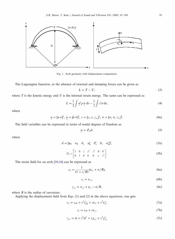
The higher-order displacement model, based on Taylor’s series expansion [29], can be expressed, for anarch, as follows (Fig. 1):
u ¼ u0 þ zyx þ z2u�0 þ z3y�x, (1)
w ¼ w0 þ zyz þ z2w�0, (2)
where z is the distance from the neutral axis to any point of interest along the depth of the arch, u0 and w0 areaxial and transverse displacements in x–z plane, yx is the face rotation about y-axis and u�0; y
�x; yz; w�0 are the
higher-order terms arising out of Taylor’s series expansion and defined at the neutral axis.
ARTICLE IN PRESS
x
z
S
R
S=R β
β
u
w
t
x
z
θx
Fig. 1. Arch geometry with displacement components.
S.R. Marur, T. Kant / Journal of Sound and Vibration 310 (2008) 91–109 93
The Lagrangian function, in the absence of external and damping forces can be given as
L ¼ T �U , (3)
where T is the kinetic energy and U is the internal strain energy. The same can be expressed as
L ¼1
2
Z_u�
tr _u�dv�
1
2
Z�tsdv, (4)
where
u�¼ ½u w�t; u
�
�¼ ½ _u _w�t; � ¼ ½�x �z gxz�
t; s ¼ ½sx sz txz�t. (4a)
The field variables can be expressed in terms of nodal degrees of freedom as
u�¼ Zdd, (5)
where
d ¼ ½u0 w0 yx u�0 y�x yz w�0�t, (5a)
= (5b)
The strain field for an arch [10,16] can be expressed as
�x ¼1
ð1þ z=RÞðu;x þ w=RÞ, (6a)
�z ¼ w;z, (6b)
gxz ¼ w;x þ u;z � u=R, (6c)
where R is the radius of curvature.Applying the displacement field from Eqs. (1) and (2) in the above equations, one gets
�x ¼ �x0 þ z2��x0 þ zkx þ z3k�x, (7a)
�z ¼ �z0 þ zkz, (7b)
gxz ¼ fþ z2f� þ zwxz þ z3w�xz (7c)
ARTICLE IN PRESSS.R. Marur, T. Kant / Journal of Sound and Vibration 310 (2008) 91–10994
The strains of Eqs. (8)–(10) can be rewritten in a combined matrix form as
� ¼ Z̄�̄, (12)
where
(12a)
�̄ ¼ ½�a �b �t gs�t. (12b)
The stress–strain relationship of an orthotropic lamina in a three-dimensional state of stress can beexpressed as [30]
so ¼ Q�o, (13)
where
so ¼ ½sx; sy; sz; txy; tyz; txz�t, (13a)
�o ¼ ½�x; �y; �z; gxy; gyz; gxz�t (13b)
and Q is given by Eqs. (A.17)–(A.29), in Appendix A.By setting sy; txy; tyz equal to zero in Eq. (13) and deriving the remaining stress components from the same
equation [31], one gets the stress–strain relationship as
s ¼ C�, (14)
ARTICLE IN PRESSS.R. Marur, T. Kant / Journal of Sound and Vibration 310 (2008) 91–109 95
where
s ¼ ½sx; sz; txz�t, (14a)
(14b)
and the expressions for various C matrix elements are given by Eqs. (B.1)–(B.6), in Appendix B.The internal strain energy can be evaluated using Eqs. (12) and (14) as
U ¼1
2
Z�tsdv ¼
1
2
Z�̄tD̄�̄dx, (15)
where
D̄ ¼ b
ZZ̄
tCZ̄ dz (15a)
(15b)
(15c)
and the expansions of various D matrices are given by Eqs. (C.3)–(C.11), in Appendix C.The kinetic energy can be expressed using Eq. (5) as
T ¼1
2
Zð _d
tm̄ _dÞdx, (16)
where
m̄ ¼ bXNL
l¼1
ZðztdrlzdÞdz, (17)
where rl is the mass density of a layer and m̄ is given by Eqn. (C.12) in Appendix C.The Lagrangian function can be re-stated with Eqs. (15) and (16) as
L ¼1
2
Zð _d
tm̄ _dÞdx�
1
2
Zð�̄tD̄�̄Þdx. (18)
3. Finite element modeling
The displacements within an element can be expressed in terms of its nodal displacements in isoparametricformulations as
d ¼ Nae, (19)
where ae is a vector containing nodal displacement vectors of an element with n nodes and can be expressed as
ae ¼ ½dt1; dt
2; . . . ; d tn�t. (20)
ARTICLE IN PRESSS.R. Marur, T. Kant / Journal of Sound and Vibration 310 (2008) 91–10996
Similarly, the strains with in an element can be written through Eqs (5a) and (12b) as
�̄ ¼
Ba
Bb
Bt
Bs
26664
37775ae ¼ B̄ae, (21)
where, for a given node n, the strain displacement matrix can be computed as
(22)
(23)
(24)
Bs ¼
�N=R N ;x N 0 0 0 0
0 0 0 �N=R 3N 0 N ;x
0 0 �N=R 2N 0 N ;x 0
0 0 0 0 �N=R 0 0
266664
377775
n
. (25)
By substituting Eqs. (19) and (21) in Eq. (18), one gets
L ¼1
2_at
e
ZN tm̄N dx _ae �
1
2at
e
ZB̄tD̄B̄dxae. (26)
Applying Hamilton’s principle on L, we get the governing equation of motion as
M €d þ Kd ¼ 0, (27)
where
M ¼
ZN tm̄N dx (27a)
and
K ¼
ZB̄tD̄B̄dx. (27b)
This equation of motion can be solved by expressing the displacement vector as
d ¼ d̄eiot ¼ d̄ðcos otþ i sin otÞ, (28)
where d̄ is the modal vector and o the natural frequency. Substituting Eq. (28) into Eq. (27), one gets
ðK � o2MÞd̄ ¼ 0. (29)
By solving Eq. (29), using standard eigenvalue solvers [32], after applying suitable boundary conditions, thenatural frequencies and corresponding mode shapes are directly obtained.
4. Numerical experiments
Numerical experiments have been carried out to study the performance of the proposed higher-order model.This model is validated by comparing its results with those available in the literature. Details such as materialproperties, lamination scheme and end conditions of every problem solved, are given in Table 1.
r ¼ 0.00049426N s2/cm4, t ¼ 5.9827 cm (for R/r ¼ 25)
r ¼ 0.002767856N s2/cm4, t ¼ 1.0683 cm (for R/r ¼ 140)
FNP : S2
ffiffiffiffiffiffiffiffiffiffi12rE1t2
rNo. of elements: 30 cubic
S.R. Marur, T. Kant / Journal of Sound and Vibration 310 (2008) 91–109 97
ARTICLE IN PRESS
Table 1 (continued )
1.3. Material data
No. Details Ref.
BC:SS
Data-4 [9,25]E1
E2¼ 15; E2 ¼ E3;
G12
E2¼ 0:6;
G23
E2¼ 0:6;
G13
E2¼ 0:6
n ¼ 0:25; r ¼ 1; b ¼ 1; t ¼ 1
S/t ¼ 100
Lamination scheme: 0/90
FNP : S2
ffiffiffiffiffiffiffiffiffiffi12rE1t2
rNo. of elements: 15 cubic
BC:CC
Data-5 [7,13]
E1 ¼ E2 ¼ E3 ¼ 3.04� 107 lb/in2
G12 ¼ G23 ¼ G13 ¼ 1.16923� 107 lb/in2
R ¼ 12 in
n ¼ 0:3r ¼ 0.02763 lb s2/in4, b ¼ 1 in, t ¼ 0.25 in
No. of elements: 30 cubic
BC:SS1
Data-6 [18]E1
E2¼ 1; E2 ¼ E3;
G12
E2¼ 0:5;
G23
E2¼ 0:5;
G13
E2¼ 0:5
n ¼ 0:25; r ¼ 1; b ¼ 1; t ¼ 1
S ¼ 20
FNP : R2
ffiffiffiffiffiffiffiffiffiffi12rE1t2
rNo. of elements: 15 cubic
BC: SS, CC
Data-7 [1]
S ¼ 28 in, R ¼ 168.06
Face sheet:
Ex ¼ Ey ¼ Ez ¼ 1.0� 107 lb/in2
n ¼ 0:3r ¼ 2.5098� 10�4 lb s2/in4
bf ¼ 1 in
tf (top, bot) ¼ 0.018 in
Core:
Gxy ¼ Gyz ¼ Gxz ¼ 12.0� 103 lb/in2
n ¼ 0:3r ¼ 3.0717� 10�6 lb s2/in4
bc ¼ 1 in
tc ¼ 0.5 in
No. of elements: 30 cubic
BC:SS, CC, CF
S.R. Marur, T. Kant / Journal of Sound and Vibration 310 (2008) 91–10998
A laminated cross-ply arch modeled by a spline function and first-order shear theory [26] is analyzed usingthe present higher-order model (Table 2). One can observe close agreement between the results of presentformulation and of spline functions. When the subtended angle is 1801, the first mode of vibration is axial,which is not reported in Ref. [26]. The remaining flexural modes compare well between the two.
Next, a cross-ply arch with varying aspect ratios and orthotropy is studied (Table 3). Flexural frequenciesof thicker as well as thinner sections, predicted by the present theory match quite well with those ofRef. [10].
ARTICLE IN PRESS
Table 2
Normalized natural frequencies of cross-ply laminated arch (Data-1)
b (deg) Mode S/t ¼ 20 S/t ¼ 100
Ref. [26] Present Ref. [26] Present
5.72958 1 4.6463 4.6558 4.6981 4.6927
2 17.9626 18.0615 18.8138 18.7805
3 38.4482 38.6491 42.339 42.1740
4 64.5268 63.3820 75.2691 74.7454
57.2958 1 4.0568 3.7680 4.0422 3.7203
2 17.6089 17.5318 18.1587 17.8247
3 38.4293 38.7940 41.6581 41.3503
4 64.8491 65.5431 74.4162 74.1199
180 1 – 0.1563(a) – 0.0723 (a)
2 12.7163 11.6498 12.743 11.6111
3 34.2522 33.3266 36.0239 34.6083
4 61.7930 61.2770 68.9281 67.4113
(a) Axial frequency.
Table 3
Normalized natural frequencies of cross-ply laminated arch (Data-2)
S.R. Marur, T. Kant / Journal of Sound and Vibration 310 (2008) 91–109 99
A 901 isotropic arch with different R/r ratios is studied (Table 4) and results are compared with earlierinvestigations. In the case of deep arch, current results match well with those of a field consistent formulationincorporating shear deformation and rotatory inertia [6]. As the formulations of Veletsos et al. [3] andRaveendranath et al. [24] do not consider transverse shear, their systems are stiffer predicting higherfrequencies than those of current higher-order model and Ref. [6], for deep sections. The fourth and fifthfrequencies of higher-order model turn out to be coupled modes, wherein the axial and flexural displacementsare predominant, as shown in Figs. 2 and 3, while the seventh mode is a pure axial mode (Fig. 4).
In the case of shallow and thin arches, the results of present model and those of Refs. [3,24] can be seen to bein good agreement, for all modes. It is interesting to see the fifth vibration mode of current model, which isflexural, where in the entire transverse displacement being on the positive y-axis (Fig. 5).
Another cross-ply clamped arch is analyzed for various internal angles—zero to P radians (Table 5). For allthe internal angles, close agreement between the present model and earlier works can be observed.
In Table 6, natural frequencies of a simply supported circular arch, reported by Heppler [7], Krishnan et al.[13] and Tufekci [19] are compared with those of present higher-order theory. One can observe that the
ARTICLE IN PRESS
Table 4
Normalized natural frequencies of hinged circular arch (Data-3)
S.R. Marur, T. Kant / Journal of Sound and Vibration 310 (2008) 91–109100
prediction of the current formulation being quite closer to those of an exact solution [19] for the entire range ofsubtended angles. Similarly, close agreement between the finite element results [13] and the present theory canbe seen, for the fundamental mode. However, the considerable difference between the results of Heppler [7]and the rest, at higher internal angles and in higher modes can be attributed [19] to the adoption of a constantnumber of (eight) straight beam elements to model the arch by Heppler. As the arc length increases with theincrease in subtended angle, employing constant number of elements would be inadequate to model the arch
ARTICLE IN PRESS
Fig. 4. Pure axial mode.
Fig. 5. Pure flexural mode.
Table 5
Normalized natural frequencies of cross-ply laminated arch (Data-4)
b Ref. [25] Ref. [9] Present
Beam 10.66 10.661 10.6507
0.01 10.86 10.866 10.8559
0.02 11.46 11.459 11.4492
0.05 14.95 14.941 14.9364
0.1 23.33 23.265 23.2665
0.2 29.52 29.311 29.2704
0.3 29.47 29.236 29.2179
0.4 29.39 29.137 29.1409
0.5 29.3 29.015 29.0398
0.8 28.86 28.513 28.5972
1 28.46 28.074 28.1931
2 25.44 24.936 25.1595
3.14 20.94 20.441 20.6711
S.R. Marur, T. Kant / Journal of Sound and Vibration 310 (2008) 91–109 101
accurately, resulting in errors. It can be seen that the fundamental mode of vibration becomes axial, as theinternal angle reaches 1801 or more; for the rest it remains flexural. This is an ideal example for the validationof the current model, possibly for the widest range of internal angles from 101 to 3501.
ARTICLE IN PRESS
Table 6
Natural frequencies (rad/s) of hinged circular arch (Data-5)
b (deg) o1 o2 o3 o4
10 Ref. [7] 5849.90 19852.00 41173.00 50054.00
Ref. [13] 5874.30 – – –
Present 5770.90 19781.84 41003.16 47936.1 (a)
20 Ref. [7] 2830.20 5248.30 11642.00 20149.00
Ref. [13] 2823.1 – – –
Ref. [19] 2827.48 5246.73 11587.2 19825.8
Present 2780.82 5225.06 11538.92 19762.23
30 Ref. [7] 2339.70 2528.30 5385.40 9438.10
Ref. [13] 2345.20 – – –
Present 2328.92 2495.36 5317.66 9161.29
60 Ref. [7] 560.24 1246.1 2456.7 2642.4
Ref. [13] 561.2 – – –
Ref. [19] 560.074 1226.61 2339.14 2627.75
Present 557.60 1221.73 2329.03 2606.59
90 Ref. [7] 229.77 553.63 1102.30 1786.70
Ref. [13] 230.4 – – –
Ref. [19] 229.591 538.332 1024.89 1583.23
Present 228.5753 536.0288 1020.37 1576.60
120 Ref. [7] 115.64 307.39 630.97 1060.80
Ref. [13] 116.3 – – –
Ref. [19] 115.609 291.549 562.463 887.37
Present 115.0986 290.2717 559.9642 883.4933
150 Ref. [7] 64.44 196.66 422.55 732.19
Ref. [13] 64.93 – – –
Ref. [19] 64.4161 177.256 348.716 559.208
Present 64.1331 176.4696 347.1570 556.7321
180 Ref. [7] 37.865 139.94 318.18 568.26
Ref. [13] 38.24 – – –
Ref. [19] 37.8485 115.541 233.152 380.269
Present 37.684 (a) 115.0254 232.1072 378.5670
210 Ref. [7] 22.77 108.63 261.71 480.28
Ref. [13] 23.05 – – –
Ref. [19] 22.7629 78.7429 163.964 272.348
Present 22.6663 (a) 78.3909 163.2276 271.1246
240 Ref. [7] 13.67 90.37 229.03 429.69
Ref. [13] 13.87 – – –
Ref. [19] 13.6592 55.252 119.464 202.425
Present 13.604 (a) 55.0052 118.9269 201.5166
270 Ref. [7] 7.9246 79.1120 208.6300 398.2100
Ref. [13] 8.06 – – –
Ref. [19] 7.9204 39.5021 89.2883 154.649
Present 7.8922 (a) 39.3263 88.8871 153.9523
300 Ref. [7] 4.1855 71.6810 194.7800 376.8200
Ref. [13] 4.27 – – –
Ref. [19] 4.184 28.5533 67.9828 120.633
Present 4.1749 (a) 28.4273 67.6777 120.0914
330 Ref. [7] 1.6922 66.3930 184.5400 360.9000
Ref. [13] 1.73 – – –
Ref. [19] 1.6918 20.7348 52.4561 95.6193
Present 1.701 (a) 20.6446 52.2222 95.1927
S.R. Marur, T. Kant / Journal of Sound and Vibration 310 (2008) 91–109102
ARTICLE IN PRESS
Table 6 (continued )
b (deg) o1 o2 o3 o4
350 Ref. [7] 0.2440 63.5870 178.9000 352.1000
Ref. [13] 0.5000 – – –
Present 0.5354 (a) 16.6763 44.1700 82.1122
(a) Axial frequency.
Table 7
Normalized natural frequencies of clamped arch (Data-6)
b SS b CC
Ref. [18] Present Ref. [18] Present
pi/3 33.63 33.2042 Pi 4.3844 4.2466
pi/2 13.762 13.6061 13pi/10 2.1335 2.0715
pi 2.2669 2.2574 3pi/2 1.3948 1.3577
4pi/3 0.818 0.8235 9pi/5 0.7885 0.7713
3pi/2 0.4742 0.4837 2pi 0.5662 0.5563
Table 8
Natural frequencies (Hz) of sandwich arch (Data-7)
Mode Ref. [1] Ref. [33] Ref. [14] Present
CC
1 264.2 240.0 244.6 243.2431
2 522.0 474.0 485.6 477.4111
3 889.0 843.0 859.8 839.3961
4 1312.0 1253.0 1276.0 1237.50
5 1767.0 1697.0 1725.0 1664.37
6 – – 2190.0 2103.31
7 – – 2668.0 2550.20
8 – – 3151.0 2998.08
Mode Ref. [1] Ref. [14] Present
SS
1 199.5 182.7 182.2877
2 394.0 351.4 348.2241
3 746.0 726.1 714.3247
4 1175.0 1162.0 1135.0752
5 1639.0 1633.0 1585.4760
6 – 2118.0 2044.8443
7 – 2611.0 2506.7768
8 – 3104.0 2966.0851
Mode Ref. [1] Ref. [14] Present
CF
1 179.0 33.8 33.74
2 266.0 198.5 197.04
3 546.0 513.0 505.07
4 934.0 910.0 889.61
5 1379.0 1356.0 1317.20
6 – 1657.0 1655.70 (a)
7 – 1831.0 1768.83
8 – 2316.0 2225.18
(a) Axial frequency.
S.R. Marur, T. Kant / Journal of Sound and Vibration 310 (2008) 91–109 103
ARTICLE IN PRESSS.R. Marur, T. Kant / Journal of Sound and Vibration 310 (2008) 91–109104
Another isotropic arch with SS and CC end conditions and various internal angles, up to 3601, is analyzedand compared with the results of ref. [18]. Close agreement between the two can be observed in Table 7.
Next, a sandwich arch analyzed earlier by Ahmed [1,33] and later by Sakiyama et al. [14] is studied using thepresent model (Table 8). As the first work of Ahmed [1] did not capture the transverse shear deformation, itsfrequency predictions have been quite high compared with other works, for all types of end conditions;while his subsequent work [33] on shear deformable sandwich beam agrees closely with the present model andRef. [14], for clamped–clamped condition. The magnitude of frequencies of higher-order theory can be seen tobe closer to those of first-order theory with a constant shear strain approximation [14], as the arch is a thin onewith a S/t ratio of 52. As the current model employs additional higher-order degrees of freedom, it becomesmore flexible than the rest.
These examples had been carefully chosen in order to capture the variation in curvature, aspect ratio anddegree of orthotropy, on the vibration characteristics. The accuracy and adequacy of the higher-order modelare validated, through the good agreement observed between the present model and the earlier works.
5. Conclusions
A higher-order model with transverse shear and normal strain components is formulated for studying thefree vibrations of laminated arches. The proposed model can study shallow to deep and thin to thick archgeometries quite effectively. Through the constitutive relationship, adapted from the three-dimensionalstress–strain relationship of an orthotropic lamina, even angle-ply laminates can be analyzed using one-dimensional elements. The proposed higher-order model is validated, in the first part of this paper, throughthe correlation of isotropic, orthotropic, composite and sandwich arch vibration characteristics with those ofearlier investigations. In the second part of this paper, frequency spectrums of the higher-order model areidentified and studied in greater detail.
Acknowledgments
The first author gratefully acknowledges the useful suggestions regarding the formulation, given by Dr.Manickam Ganapathi, Bangalore, during the preparation of this manuscript.
Appendix A
The stress–strain relationship at a point of an orthotropic lamina in a three dimensional state of stress/straincan be expressed, along the lamina axes, as [30] (Fig. 6)
S.R. Marur, T. Kant / Journal of Sound and Vibration 310 (2008) 91–109 107
Appendix C
Using Binomial series, the following terms can be expanded as
1
ð1þ z=RÞ¼ 1�
z
Rþ
z2
R2�
z3
R3, (C.1)
1
ð1þ z=RÞ2¼ 1�
2z
Rþ
3z2
R2�
4z3
R3, (C.2)
which are used in the evaluation of various D matrices:
Daa ¼ b
ZZaC11Zt
a dz ¼ (C.3)
Dab ¼ b
ZZaC11Zt
b dz ¼ (C.4)
Dba ¼ Dab,
Dbb ¼ b
ZZbC11Zt
b dz ¼ (C.5)
Dat ¼ b
ZZaC12Zt
t dz ¼ (C.6)
Dbt ¼ b
ZZbC12Zt
tdz ¼ (C.7)
Dta ¼ b
ZZtC21Zt
a dz ¼ (C.8)
Dtb ¼ b
ZZtC21Zt
b dz ¼ (C.9)
Dtt ¼ b
ZZtC22Zt
t dz ¼ bXNL
l¼1
C22
H1 H2
H2 H3
" #, (C.10)
Dss ¼ b
ZZsC33Zt
sdz ¼ bXNL
l¼1
C33
H1 H3 H2 H4
H5 H4 H6
H3 H5
Sym H7
266664
377775, (C.11)
ARTICLE IN PRESSS.R. Marur, T. Kant / Journal of Sound and Vibration 310 (2008) 91–109108
m̄ ¼ bXNL
l¼1
rl
H1 0 H2 H3 H4 0 0
H1 0 0 0 H2 H3
H3 H4 H5 0 0
H5 H6 0 0
H7 0 0
Sym H3 H4
H5
2666666666664
3777777777775. (C.12)
In Eqs. (C.3)–(C.12), for a given layer l,
Hk ¼1
kðhk
l � hkl�1Þ, (C.13)
where NL is the total number of layers of a cross-section, k the constant varying from 1 to 10, hl the distancefrom the neutral axis to the top of a layer, l, hl�1 the distance from the neutral axis to the top of layer l�1 orbottom of layer l.
References
[1] K.M. Ahmed, Free vibration of curved sandwich beams by the method of finite elements, Journal of Sound and Vibration 18 (1971)
61–74.
[2] M. Petyt, C.C. Fleischer, Free vibration of a curved beam, Journal of Sound and Vibration 18 (1971) 17–30.
[3] A.S. Veletsos, W.J. Austin, C.A.L. Pereira, S.J. Wung, Free in plane vibration of circular arches, ASCE Journal of Engineering
Mechanics Division 98 (1972) 311–329.
[4] W.J. Austin, A.S. Veletsos, Free vibration of arches flexible in shear, ASCE Journal of Engineering Mechanics Division 99 (1973)
735–753.
[5] K. Singh, B.P. Singh, Finite element method for in plane vibrations of rotating Timoshenko rings and sectors, International Journal
for Numerical Methods in Engineering 21 (1985) 1521–1533.
[6] T.S. Balasubramanian, G. Prathap, A field consistent higher-order curved beam element for static and dynamic analysis of stepped
arches, Computers & Structures 33 (1989) 281–288.
[7] G.R. Heppler, An element for studying the vibration of unrestrained curved Timoshenko beams, Journal of Sound and Vibration 158
(1992) 387–404.
[8] M.S. Qatu, In plane vibration of slightly curved laminated composite beams, Journal of Sound and Vibration 159 (1992) 327–338.
[9] M.S. Qatu, A.A. Elsharkawy, Vibration of laminated composite arches with deep curvature and arbitrary boundaries, Computers &
Structures 47 (1993) 305–311.
[10] M.S. Qatu, Vibration of Laminated Shells and Plates, Elsevier Ltd., Oxford, 2004.
[11] N.M. Auciello, M.A. De Rosa, Free vibrations of circular arches: a review, Journal of Sound and Vibration 176 (1994) 433–458.
[12] A. Krishnan, Y.J. Suresh, A simple cubic linear element for static and free vibration analyses of curved beams, Computers &
Structures 68 (1998) 473–489.
[13] A. Krishnan, S. Dharmaraj, Y.J. Suresh, Free vibration studies of arches, Journal of Sound and Vibration 186 (1995) 856–863.
[14] T. Sakiyama, H. Matsuda, C. Morita, Free vibration analysis of sandwich arches with elastic or visco elastic core and various kinds of
axis shape and boundary conditions, Journal of Sound and Vibration 203 (1997) 505–522.
[15] Y.P. Tseng, C.S. Huang, C.J. Lin, Dynamic stiffness analysis for in-plane vibrations of arches with variable curvature, Journal of
Sound and Vibration 207 (1997) 15–31.
[16] Y.P. Tseng, C.S. Huang, M.S. Kao, In-plane vibration of laminated curved beams with variable curvature by dynamic stiffness
analysis, Composite Structures 50 (2000) 103–114.
[17] K. Kang, C.W. Bert, A.G. Striz, Vibration analysis of shear deformable circular arches by the differential quadrature method, Journal
of Sound and Vibration 181 (1995) 353–360.
[18] K. Kang, C.W. Bert, A.G. Striz, Vibration and buckling analysis of circular arches using DQM, Computers & Structures 60 (1996)
49–57.
[19] E. Tufekci, A. Arpaci, Exact solution of in-plane vibrations of circular arches with account taken of axial extension, transverse shear
and rotatory inertia effects, Journal of Sound and Vibration 209 (1998) 845–856.
[20] V. Yildirim, Rotary inertia, axial and shear deformation effects on the in-plane natural frequencies of symmetric cross-ply laminated
circular arches, Journal of Sound and Vibration 224 (1999) 575–589.
[21] V. Yildirim, Common effects of the rotary inertia and shear deformation on the out-of-plane natural frequencies of composite
circular bars, Composites Part B: Engineering 32 (2001) 687–695.
[22] H. Matsunaga, Free vibration and stability of laminated composite circular arches subjected to initial axial stress, Journal of Sound
and Vibration 271 (2004) 651–670.
ARTICLE IN PRESSS.R. Marur, T. Kant / Journal of Sound and Vibration 310 (2008) 91–109 109
[23] A.A. Khdeir, J.N. Reddy, Free and forced vibration of cross-ply laminated composite shallow arches, International Journal of Solids
and Structures 34 (1997) 1217–1234.
[24] P. Raveendranath, G. Singh, B. Pradhan, Free vibration of arches using a curved beam element based on a coupled polynomial