FRYER MACHINE SYSTEMS MC-E SERIES MECHANICAL MANUAL FRYER MACHINE SYSTEMS, INC. 70 JON BARRETT ROAD ROBIN HILL CORPORATE PARK PATTERSON, NY 12563 PHONE: 845-878-2500 FAX: 845-878-2525 WWW.FRYERMACHINE.COM
Transcript
FRYER MACHINE SYSTEMS MC-E SERIES
MECHANICAL MANUAL
FRYER MACHINE SYSTEMS, INC. 70 JON BARRETT ROAD
ROBIN HILL CORPORATE PARK PATTERSON, NY 12563 PHONE: 845-878-2500
MECHANICAL DRAWINGS....................................................................................................................................................3 HEAD ASSEMBLY..................................................................................................................................................................4 Z AXIS COLUMN ....................................................................................................................................................................5 Z AXIS RAM.............................................................................................................................................................................6 X AXIS TABLE ........................................................................................................................................................................7 X AXIS BALL SCREW ............................................................................................................................................................8 Y AXIS SADDLE .....................................................................................................................................................................9 Y AXIS BALL SCREW ..........................................................................................................................................................10 TOOL CHANGER ..................................................................................................................................................................11 BED AND COLUMN .............................................................................................................................................................12 COUNTER WEIGHT..............................................................................................................................................................13 MC SHEET METAL ...............................................................................................................................................................14 RETENTION KNOBS ............................................................................................................................................................15
maintenance MC E SERIES.doc 2 OF 15
MECHANICAL DRAWINGS
maintenance MC E SERIES.doc 3 OF 15
HEAD ASSEMBLY
maintenance MC E SERIES.doc 4 OF 15
Z AXIS COLUMN
maintenance MC E SERIES.doc 5 OF 15
Z AXIS RAM
maintenance MC E SERIES.doc 6 OF 15
X AXIS TABLE
maintenance MC E SERIES.doc 7 OF 15
X AXIS BALL SCREW
maintenance MC E SERIES.doc 8 OF 15
Y AXIS SADDLE
maintenance MC E SERIES.doc 9 OF 15
Y AXIS BALL SCREW
maintenance MC E SERIES.doc 10 OF 15
TOOL CHANGER
maintenance MC E SERIES.doc 11 OF 15
BED AND COLUMN
maintenance MC E SERIES.doc 12 OF 15
COUNTER WEIGHT
maintenance MC E SERIES.doc 13 OF 15
MC SHEET METAL
maintenance MC E SERIES.doc 14 OF 15
FRY
ER
PA
RT
NU
MB
ER
S
CA
T 40
TOL-
5450
BT
40TO
L-54
56
CA
T 50
TOL-
5454
NO
TE:
IF T
HR
U C
OO
LAN
T IS
NEE
DED
, PLE
AS
E C
ALL
FOR
PR
OPE
R
PAR
T N
UM
BER
RETENTION KNOBS
maintenance MC E SERIES.doc 15 OF 15
FRYER MACHINE SYSTEMS ELECTRICAL &
PROCEDURES MANUAL ANILAM 6000i CONTROL
FRYER MACHINE SYSTEMS, INC. 70 JON BARRETT ROAD
ROBIN HILL CORPORATE PARK PATTERSON, NY 12563 PHONE: 845-878-2500
1. PREVENT LOOSE CLOTHING, HAIR, JEWELRY FROM CONTACTING SPINDLE 2. NEVER: CHANGE TOOLS, HANDLE SPINDLE, CHANGE PARTS OR PERFORM WORK
ON MILL UNLESS CNC IS IN EMERGENCY STOP OR TOOL CHANGE MODES 3. ALWAYS WEAR EYE PROTECTION WHEN OPERATING MILL. 4. DO NOT OPERATE MILL WITHOUT AXIS MOTOR COVERS OR AXIS WAY COVERS IN
PLACE. 5. DO NOT PLACE OBJECTS OR HANDS BETWEEN COLUMN AND TABLE/SADDLE
ASSY, UNLESS CNC IS IN EMERGENCY STOP POSITION. 6. DO NOT MODIFY EQUIPMENT WITHOUT APPROVAL FROM FRYER MACHINE
SYSTEMS. DOING SO MAY VOID YOUR WARRANTY. 7. ELECTRICAL ENCLOSURES CONTAIN HIGH VOLTAGE. DISCONNECT EQUIPMENT
FROM POWER SOURCE BEFORE OPENING CABINETS. 8. CHECK LUBRICANT FILL LEVELS BEFORE OPERATING. 9. DO NOT OPERATE POWER DRAWBAR UNIT WHILE SPINDLE IS IN MOTION. 10. EMERGENCY STOP MILL WHEN NOT IN USE 11. KEEP VISES, CLAMPS, FIXTURE OR WORKPIECE FROM EXTENDING BEYOND BACK
EDGE OF TABLE. 12. TURN OFF POWER IF:
POWER PROBLEMS DEVELOP IN THE EVENT OF ELECTRICAL STORMS. AMBIENT TEMPERATURES EXCEED 105 DEGREES FARENHEIT.
Electrical Manual Anilam 6000i.doc Page 3 of 25
STARTUP PROCEDURE FOR FRYER VB/MC SERIES MILLS WITH ANILAM 6000i CONTROLLERS
Unpack Machine:
1. Remove plastic wrap. Carefully inspect for any damage. 2. Install leveling pads and level machine. (This is usually the responsibility of the rigger or
customer) Assistance will be necessary to perform the following steps:
3. Using a socket or suitable wrench (Pliers are not recommended) turn the Z ballscrew clockwise from the top of the screw enough to remove wooden shipping block on table. Be careful not to let the ratchet/wrench slip backwards.
4. Turn the ratchet/wrench counter clockwise until counterweight chains are taut, and counterweight bar is free
5. Remove counterweight bar. At this time you must remove the ratchet/wrench otherwise serious damage could occur.
6. Install the Z-Axis motor and drive belt, and any other items that may have been removed for shipping purposes. Make sure to align marks on direct drive coupling if equipped. Do not tighten motor locking bolts until motor is floated into center.
7. Check that front panel with swivel arm is clear of Z-Axis head motion. (If equipped) 8. Optional ATC: Remove the carousel support bolted to the table. Remove the locking orange
bracket to prevent the carousel to slide back and fourth(mounted on rear of atc next to large air cylinder).
Line voltage check: 1. Verify 230/460 vac. (+/- 10%) is wired to the main disconnect correctly. (460vac. Optional).
The factory configuration is stamped on the serial number plack. The transformer equipped with all 6000i controls has multiple taps, that should be configured for 400VAC at the control amplifier input. See documentation included with this manual.
2. Check all wire connections, relays, contacts, and plugs to be sure nothing has come loose. If so, reseat or tighten before turning on main power.
All voltage checks should be recorded on the STARTUP REPORT form. Machine power-up procedure:
1. Turn the 230/460VAC disconnect switch rod on the electrical cabinet with a pair of pliers a ¼ turn clockwise.
2. Boot-up the control. 3. Release the E-stop switch and press SERVO RESET to engage servo drives.
Electrical Manual Anilam 6000i.doc Page 4 of 25
Voltage checks (All voltages +/- 10%):
1. Check for 110vac: terminal strip #1 AC hot #2 AC neutral 2. Check for 220 vac 3 phase: terminal strip #13- #14- #15 3. Check for 400 vac 3 phase: terminal strip #L1-#L2-#L3 4. Check for +24vdc: terminal strip #12=24 vdc #20=com
Additional Checks:
1. Make sure way surfaces are receiving sufficient oil from pump. 2. Make sure air pressure to regulator-lubricator unit is set at 90 psi minimum. 3. Check the tool change height and orient position. 4. Check for proper phasing on all three phase motors. Especially arm style ATC carousel motor,
flood pump, wash-down pump, chip auger, and spindle motor fan. All information should be recorded on a Fryer Machine Startup Form with any unusual conditions listed and returned to Fryer Machine Service Dept. If any problems are encountered or if you have any questions, please contact FRYER MACHINE SYSTEMS Service Department at (845) 878-2500.
Electrical Manual Anilam 6000i.doc Page 5 of 25
STARTUP REPORT - ANILAM 6000i Control
CUSTOMER__________________________DATE: ____________________ MODEL #: ____________________ SERIAL #: _________________ CONTROL SN#: ____________________ DISTRIBUTOR: _______________________________ SERVICE TECH: _________________________________ SHOP CONTACT: __________________________________ TITLE:___________________________________
ATTENTION: ITEMS CAN BECOME LOOSE DURING SHIPPING CAUSING A LOSS OF CONNECTIONS. THIS MAY RESULT IN IMPROPER MACHINE FUNCTION AND/OR DAMAGE TO THE MACHINE OR COMPONENTS. BEFORE INITIAL POWER-UP: TIGHTEN ALL SCREWS AND ELECTRICAL CONNECTIONS IN THE ELECTRICAL CABINET . CHECK TO ENSURE THAT ALL ELECTRICAL COMPONENTS ARE PROPERLY SEATED AND SECURED.
ELECTRICAL CONNECTIONS AND COMPONENTS CHECKED: _________
ELECTRIAL CABINET 220/440vac: ________ (MAIN DISCONNECT SWITCH) 110vac: ________ (tb#1- tb#2) 400vac: ________ (tb#L1-tb#L2-tb#L3) 24vdc: ________ (tb#12-tb#20) AIR PRESSURE: _________ WAYLUBE PRESENT AT X, Y & Z BOX WAY SURFACES. __________ HOUR METER READING ______________ COUPLING ORIENTATION AND AXIS TRAVEL CHECKED _____________________
INITIAL START-UP QUALITY SURVEY At Fryer Machine Systems, we strive to continuously improve the quality of our products and services. As a qualified machine tool technician, your feedback is an essential part of this ongoing process. Please take a moment to fill out the following information. It will be greatly appreciated. Please circle the appropriate response (1=worst, 5=best) for each question. Feel free to add any comments.
Electrical Manual Anilam 6000i.doc Page 6 of 25
MISSING PARTS Were there any parts missing? ............................................................................................Yes No If yes, what was missing? ____________________________________________________________________________ ____________________________________________________________________________ ____________________________________________________________________________ INITIAL IMPRESSIONS Was machine received in satisfactory condition? ................................................................Yes No If no, what was lacking? ____________________________________________________________________________ ____________________________________________________________________________ ____________________________________________________________________________ Please rate the overall appearance of the machine: ............................................................1 2 3 4 5 Comments: ____________________________________________________________________________ ____________________________________________________________________________ ____________________________________________________________________________ PERFORMANCE Please rate the mechanical systems of the machine: ..........................................................1 2 3 4 5 ____________________________________________________________________________ ____________________________________________________________________________ ____________________________________________________________________________ Please rate the electrical systems of the machine: ..............................................................1 2 3 4 5 Comments: ____________________________________________________________________________ ____________________________________________________________________________ ____________________________________________________________________________ SERVICE Were there any problems with the machine during start-up? ...............................................Yes No If yes, please list: ____________________________________________________________________________ ____________________________________________________________________________ ____________________________________________________________________________ What issues, if any, are still outstanding? ____________________________________________________________________________ ____________________________________________________________________________ ____________________________________________________________________________ Was our Service Dept. helpful during the start-up? Please rate us: .....................................1 2 3 4 5 ADDITIONAL COMMENTS: _______________________________________________________________________________________________________________________________________________________________________________________________________________________________________________________________________________________________________________
Electrical Manual Anilam 6000i.doc Page 7 of 25
PANEL LAYOUT
Electrical Manual Anilam 6000i.doc Page 8 of 25
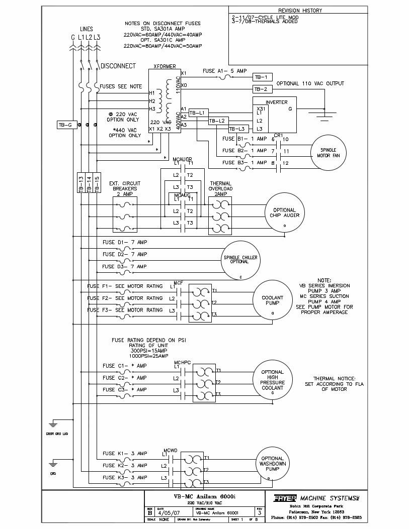
Fryer Mill with Anilam 6000 and 20KVA Transformer Setup
The Anilam 6000 control requires special secondary voltage of 400 vac. This requires a special transformer to be installed on all mills equipped with this control. The 20KVA transformer is used on all mills except ones with the 30 Horsepower spindle option. The transformer is pre-wired at the factory for the primary voltage specified at time of order and the machine serial number tag. Main input power must ONLY be connected to the line side (TOP) of the disconnect switch located inside the electrical cabinet. NEVER connect main power directly to the Transformer. Following is an explanation of how to configure the transformer (all wiring changes are done inside the transformer) for the two most common incoming primary voltage ranges. Refer to the specifications on the front cover of the transformer for other possible inputs (210 – 483 V). For 208-250 VAC input (Voltage must be within this range or warranty will be void.), connect the internal tap wires from H1-H2-H3 to each corresponding tap (4=250, 5=230, 6=210) respectively (one wire per phase). The 3- 12 AWG black wires labeled as 13-14-15 should be connected to H1, H2, H3 respectively alongside with the input AC wires ONLY when 208 – 250 volt primary is used. For 420-495 VAC input (Voltage must be within this range or warranty will be void), connect the internal tap wires from H1-H2-H3 to each corresponding tap (1=483, 2=460, 3=437) respectively (one wire per phase). The 3- 12 AWG black wires labeled as 13-14-15 should be connected to X1-13, X2-14, X3-15
Electrical Manual Anilam 6000i.doc Page 9 of 25
Fryer Mill with Anilam 6000i Controls and 25KVA
Transformer Setup The Anilam 6000 control requires special voltage of 400 volts AC. This requires a special transformer to be installed on all mills equipped with this control. The 25 KVA transformer is only used on mills equipped with the 30 HP spindle motor. The transformer is pre-wired at the factory for the primary voltage specified on the order and the machine serial number tag. Main input power is ALWAYS connected to the line side of the disconnect switch located inside the electrical cabinet. NEVER connect main power directly to Transformer wires. Following is an explanation of how to configure the transformer ( all wiring changes are done inside the transformer) for the two possible incoming voltage ranges. For 208-250 VAC input (Voltage must be within this range or warranty will be void.), connect the wires with white insulation from H1-H2-H3 to corresponding taps #2 on the transformer phase columns. The 12 AWG black wires labeled as 13-14-15 should be connected to H1, H2, H3 respectively along with the input AC wires. For 420-495 VAC input (Voltage must be within this range or warranty will be void), connect the wires with white insulation from H1-H2-H3 to corresponding taps #1 on the transformer phase columns. The 12 AWG black wires labeled as 13-14-15 should be connected to Y1, Y2, Y3 respect..
Electrical Manual Anilam 6000i.doc Page 10 of 25
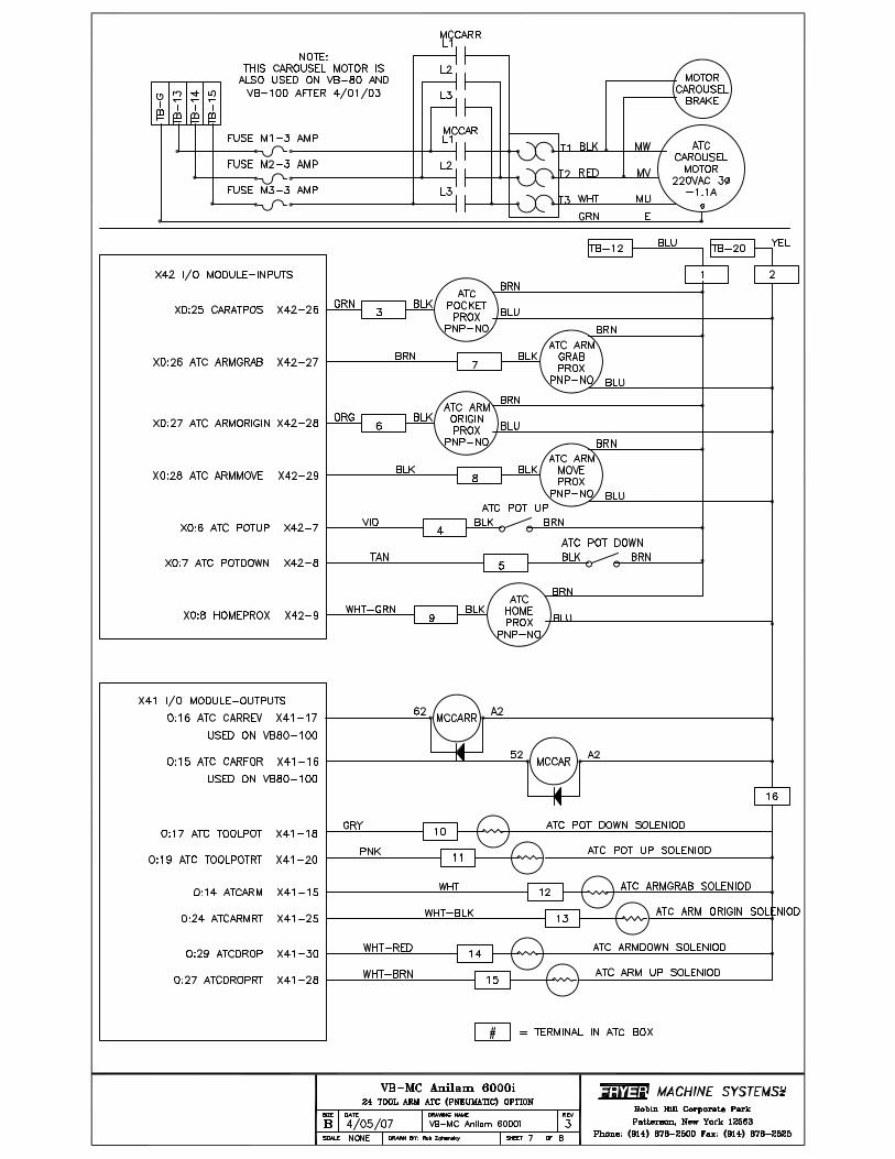
ATC Pneumatic Arm Operation and Repair with Anilam 6000i
control
ATC Operation Guidelines
• Due to the complexity and timing of the ATC, it should only be operated with the M6 command. • Never interrupt the tool changer in the middle of cycle, wait for it to complete the tool change. If a low air alarm sets and
the tool gets stuck in the spindle, then go to the recovery section on page 3 of this document. • This is a random access tool changer to reduce tool change time. The machine will always keep track of the correct tool even
though it may not agree with the bin #. You can have the carousel move to the next tool requested with a T# command on a line by itself. When a tool change is specified (M6) this tool # will be loaded into the spindle.
• If the t code is programmed on the same line as the M6 command make sure the M6 is before the T code (example: M6T4). • Most tools have a deeper notch on one side of the tools v-flange. The ATC carousel will only allow this deeper notch to fit into
the carousel key. Make sure when installing tools in spindle this orientation is verified. After spindle orientation the key slot on the v-flange of the tool furthest from the operator will align with the key on the carousel.
• The carousel motor is a 3 phase motor and must be phased correctly for proper direction. M58 will increase carousel position
to next higher tool number. The machine is phased properly at the factory before shipment, so if carousel rotates wrong direction switch any two incoming power wires at disconnect. Make sure main power breaker is off!
Manual operation of tool change solenoid valves If the tool changer gets hung up the solenoid valves can be operated manually to reset the tool changer. Here is a description
of the operation of the valves. Access the air solenoid valves for the tool changer behind the door on the front of the ATC. There is a diagram of the operation of each solenoid. These can be run manually by depressing the blue manual override buttons. Make sure you push the buttons in sequence otherwise damage could be done to the ATC. There are three two way solenoid valves mounted horizontally. The top solenoid valve controls the carousel tool pot; left button returns tool pot to up position, right button drops pot down. The middle solenoid controls the arm movement 60° under the spindle and to normal rest position. The right button moves the arm under the spindle nose to grab a tool, left button moves the arm back to its normal clearance position. The bottom solenoid controls the arm down and 180° and arm up. The right button moves the arm down and then 180°, the left button returns the arm up.
The proper sequence of a tool change and the respective M-codes is as follows: (Note that you will have to press the cycle start button twice to execute these commands) 1. T-code to move carousel to pending tool 2. M52 tool pot down 3. M68 moves z axis to tool change position 4. M60 spindle orient 5. M62 Arm moves under spindle to grab tool and carousel pot 6. M54 turns drawbar on 7. M64 Arm removes tool from spindle and carousel tool pot and swaps them 8. M65 arm up to install pending tool in spindle and old tool into carousel pot. 9. M55 Drawbar off to grab tool in spindle. 10. M63 Arm origin 11. M53 carousel tool pot up
Electrical Manual Anilam 6000i.doc Page 11 of 25
Tool Change Height Adjustment
The proper tool change height must be set for the ATC to perform correctly. The tool change height (machine coordinates from home position) is stored in parameter NP_DG_TC_pos_Z_put_in. This will have to be checked if the home position is different due to removing the z motor or home switch or dog. Here is a procedure to set this height correctly: There is some allowance ( play ) allowed for the tool change height (about .03”) This is the difference between the v flange groove of the tool and the v location of the arm . You will see this vertical play if you install a tool into the arm when the machine is in e-stop. Make sure you do not leave the tool there!
1. Home the machine. 2. Move the z-axis to the tool change height with an M68 command in manual mode. The number is derived from the distance
from home position (machine zero) to the proper height for tool change. To get to this parameter from manual mode: -Press shift -(F3) config -Password= 222 (may not be necessary if you already typed in the password) -(F6) config data -Now you will have to follow the directory tree by opening up each folder and edvancing into the proper subfolders. The path is a follows: System-PLC-cfgoemposition The parameter for tool change height is: NP_DG_TC_pos_z_put_in.
That number is in MM (millimeters) and is a negative value. Change display to read in MM to get a direct read out in the Machine Coordinates box in Z =(ex. -62.408 MM)
3. Orient the spindle with an M60 command. 4. Install a tool in the spindle. 5. Press the middle right solenoid manual button to grab the tool, see the description of manual solenoid operation. 6. Look to see if the position of the z axis will cause the v flange groove of the tool is in the center of the arm v notch. Return the
arm manually back out of way with the middle left button on the solenoid valve. Adjust the tool change height parameter outlined in step 2 and repeat until correct alignment is achieved.
7. At this time you can alternate the middle left and middle right button to check for smooth engagement of the arm into and away from the tool. If the arm doesn’t respond smoothly then further z axis height adjustment may be required.
Spindle Orient Adjustment
1. With z axis at maximum positive limit and ATC arm under spindle nose (manual solenoid button 2nd on right). Make sure spindle can be spun without spindle keys hitting ATC arm.
2. Orient spindle with M60 3. Look to see if spindle keys are in alignment with notch in the arm. 4. In manual follow the steps below to get to the orient postion parameter:
-Press shift -Password=222 (may not be necessary if you already typed in the password) -(F6) config data -Now you will have to follow the directory tree by opening up each folder and edvancing into the proper subfolders. The path is a follows: System-PLC-cfgoemposition The parameter for spindle orient position is: NP_DG_TC_pos_spindle
5. Command M5 cycle start. This will turn off the orient command. 6. Repeat steps 2 and 5 and adjust parameter until correct.
Recovering From Tool Change Failure If the tool changer fails you may get an alarm “timeout in spindle sequence”, this means that after 30 seconds of waiting a
function did not get it’s proper finish signal. You must look to see what function did not complete. It most likely had to do with movement of the arm. Look at the solenoid valves, the solenoid valve that is illuminated is the operation that failed. Press emergency stop. If the arm did not complete grabbing the tool, make sure the pot is down and then press the arm return manual button. Refer to manual operation of tool changer pneumatic solenoid valves. After the arm is returned to normal resting position, tool is removed from the spindle and carousel pot returned manually, the carousel pots may have to be reset. If the carousel does not rotate check the fuses in the electrical cabinet. Refer to electrical schematics in maintenance manual.
Electrical Manual Anilam 6000i.doc Page 12 of 25
Tool Carousel Reset
To reset all the tool bin locations follow this procedure. 1. Remove tool from spindle 2. In MDI command : M6T0 cycle start 3. Remove any tool from spindle 4. In MDI command : M61 cycle start ( this will index carousel to bin #1 ) 5. Go to tool table, soft key F9, and then press soft key F4 BIN. The bin numbers on the left hand side will be 0-#pots in
carousel, set the tool number to the same as the bin number leaving bin 0 blank. 6. Remove all tools from carousel and reinstall.
Arm Alignment
If the arm no longer moves in the proper angular alignment then an adjustment may be required. The arm is held in place on the arm shaft with a compression clamp.
1. Install tool in spindle 2. Orient spindle M60 3. Install tool in carousel pot 4. Drop carousel pot down with manual button(top right) 5. Move z axis to tool change height M68 6. Move arm to grab tools with manual button.(middle right) 7. Loosen socket head cap screws at bottom center of arm and align arm to grab tools fully. Once completed adjustment tighten
screws. 8. Move arm back to origin location with manual button (middle left) 9. Remove tools 10. Reset carousel pot back up with manual button. (top left) 11. Turn off orient with M5 command
Electrical Manual Anilam 6000i.doc Page 13 of 25
Figure 1: Pneumatic ATC unit with covers off (front view).
6 control solenoids (6) (1) (5) (2) (4) (3)
“Home” and “In Position” at spindle indicators.
Tool Pot up/down ram w/ position sensors mounted on it.
Arm Up/Down Ram
Electrical Manual Anilam 6000i.doc Page 14 of 25
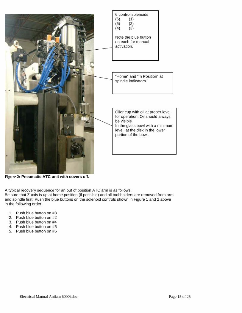
“Home” and “In Position” at spindle indicators.
6 control solenoids (6) (1) (5) (2) (4) (3) Note the blue button on each for manual activation.
Oiler cup with oil at proper level for operation. Oil should always be visible In the glass bowl with a minimum level at the disk in the lower portion of the bowl.
Figure 2: Pneumatic ATC unit with covers off.
A typical recovery sequence for an out of position ATC arm is as follows: Be sure that Z-axis is up at home position (if possible) and all tool holders are removed from arm and spindle first. Push the blue buttons on the solenoid controls shown in Figure 1 and 2 above in the following order.
1. Push blue button on #3 2. Push blue button on #2 3. Push blue button on #4 4. Push blue button on #5 5. Push blue button on #6
Electrical Manual Anilam 6000i.doc Page 15 of 25
CAROUSEL TOOL CHANGER
Electrical Manual Anilam 6000i.doc Page 16 of 25
SERIES SPECIFICATIONS Carousel Tool Changer Maintenance
Electrical Manual Anilam 6000i.doc Page 17 of 25
Electrical Manual Anilam 6000i.doc Page 18 of 25
Electrical Manual Anilam 6000i.doc Page 19 of 25
Electrical Manual Anilam 6000i.doc Page 20 of 25
COOLANT SYSTEM HOOK-UP PROCEDURE
THE COOLANT PUMP HAS 2 PORTS LOCATED ON EITHER SIDE OF THE PUMP. THE (IN) PORTS WHICH ARE A ¾” SIZE MUST BE HOOKED UP TO THE COOLANT PAN OUT PORTS. THESE ARE LOCATED ON THE LOWER REAR CORNERS OF THE MACHINE. SECURE THE HOSE USING HOSE CLAMPS, THE (OUT) SIDE OF THE PUMP HAS 3 PORTS, ONE IS A ½” HOSE AND TWO ARE A ¾” HOSE. THE ½” HOSE GETS HOOKED UP TO THE COOLANT FEED LINE AND THE ¾” HOSE GETS HOOKED UP TO THE WASHDOWN PORTS LOCATED ON BOTH SIDES OF THE MACHINE. THE WASH DOWN PORT IS EQUIPPED WITH A BALL VALVE ENABELING THE OPERATOR TO SHUT DOWN THE WASHDOWN COMPLETELY OR JUST ONE SIDE SECURE ALL LINES USING HOSE CLAMPS.
Electrical Manual Anilam 6000i.doc Page 21 of 25
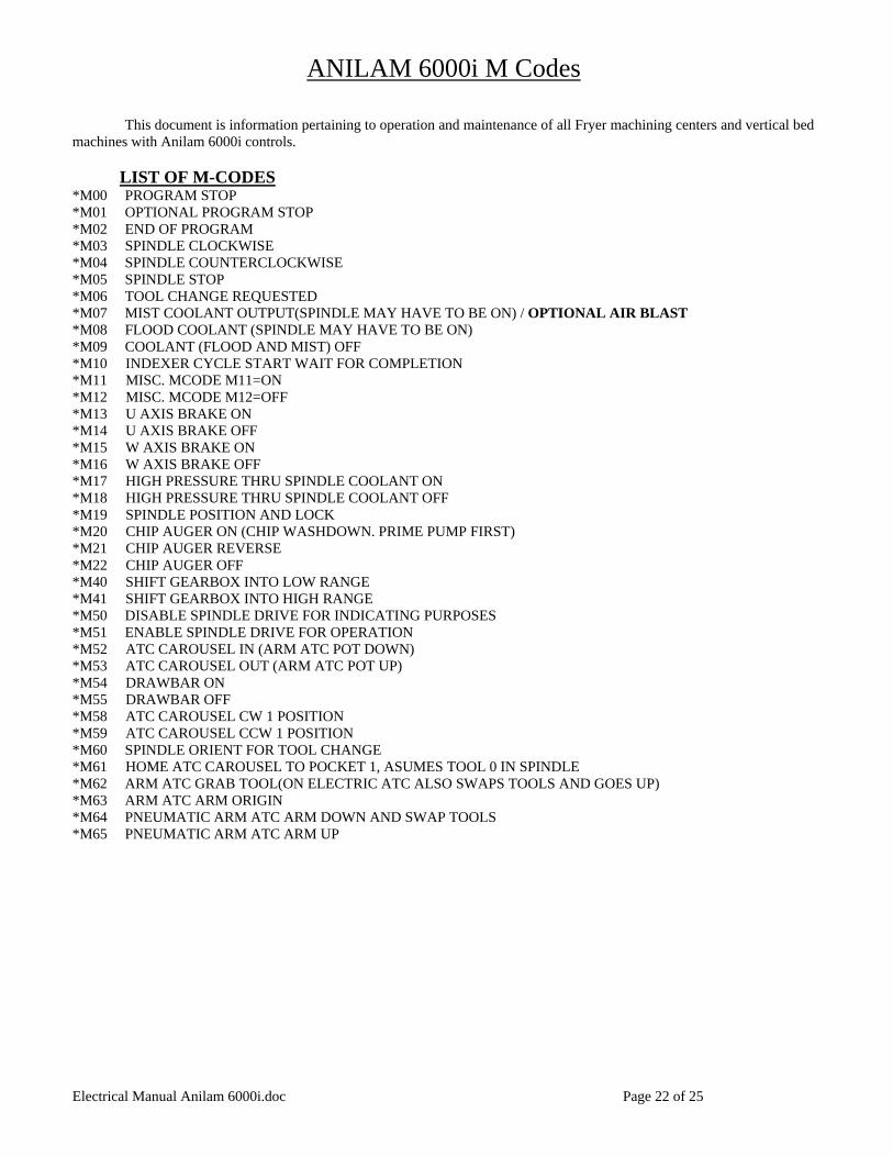
ANILAM 6000i M Codes This document is information pertaining to operation and maintenance of all Fryer machining centers and vertical bed machines with Anilam 6000i controls.
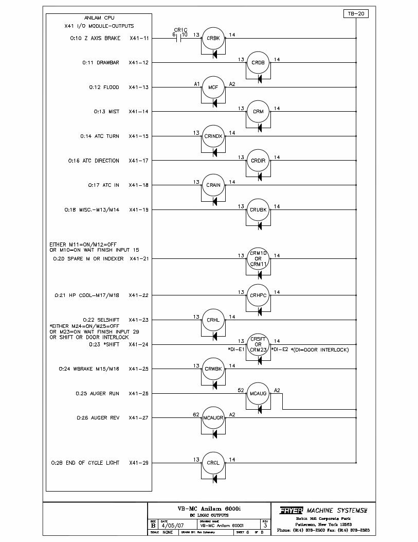
LIST OF M-CODES *M00 PROGRAM STOP *M01 OPTIONAL PROGRAM STOP *M02 END OF PROGRAM *M03 SPINDLE CLOCKWISE *M04 SPINDLE COUNTERCLOCKWISE *M05 SPINDLE STOP *M06 TOOL CHANGE REQUESTED *M07 MIST COOLANT OUTPUT(SPINDLE MAY HAVE TO BE ON) / OPTIONAL AIR BLAST *M08 FLOOD COOLANT (SPINDLE MAY HAVE TO BE ON) *M09 COOLANT (FLOOD AND MIST) OFF *M10 INDEXER CYCLE START WAIT FOR COMPLETION *M11 MISC. MCODE M11=ON *M12 MISC. MCODE M12=OFF *M13 U AXIS BRAKE ON *M14 U AXIS BRAKE OFF *M15 W AXIS BRAKE ON *M16 W AXIS BRAKE OFF *M17 HIGH PRESSURE THRU SPINDLE COOLANT ON *M18 HIGH PRESSURE THRU SPINDLE COOLANT OFF *M19 SPINDLE POSITION AND LOCK *M20 CHIP AUGER ON (CHIP WASHDOWN. PRIME PUMP FIRST) *M21 CHIP AUGER REVERSE *M22 CHIP AUGER OFF *M40 SHIFT GEARBOX INTO LOW RANGE *M41 SHIFT GEARBOX INTO HIGH RANGE *M50 DISABLE SPINDLE DRIVE FOR INDICATING PURPOSES *M51 ENABLE SPINDLE DRIVE FOR OPERATION *M52 ATC CAROUSEL IN (ARM ATC POT DOWN) *M53 ATC CAROUSEL OUT (ARM ATC POT UP) *M54 DRAWBAR ON *M55 DRAWBAR OFF *M58 ATC CAROUSEL CW 1 POSITION *M59 ATC CAROUSEL CCW 1 POSITION *M60 SPINDLE ORIENT FOR TOOL CHANGE *M61 HOME ATC CAROUSEL TO POCKET 1, ASUMES TOOL 0 IN SPINDLE *M62 ARM ATC GRAB TOOL(ON ELECTRIC ATC ALSO SWAPS TOOLS AND GOES UP) *M63 ARM ATC ARM ORIGIN *M64 PNEUMATIC ARM ATC ARM DOWN AND SWAP TOOLS *M65 PNEUMATIC ARM ATC ARM UP
Electrical Manual Anilam 6000i.doc Page 22 of 25
MAINTENANCE SCHEDULE
daily weekly monthly 3 months 6 months yearly as req’d. fill lube pump1 X
fill drawbar lube2 X check coolant level X
change coolant3 X check machine level X
check gibs X check backlash X
check belt tension X check servo cabinet
and console fans, clean filters
X
replace servo cabinet and console filters4 X
1 -Mobil Vactra #2 (ISO 68) or equivalent 2 -Break-Free Synthetic Air Tool Oil (5W) or equivalent 3 -Valenite Turn Tech Blue Metalworking Fluid or equivalent 4 -See Anilam Manual
Electrical Manual Anilam 6000i.doc Page 23 of 25
Renishaw Tool Probe Installation This will assist you in setting up and installing your Renishaw TS-27R tool probe on your Fryer milling machine with Anilam control. Make sure you read the instruction manual that came with the Renishaw probe and the Anilam manual pertaining to probing cycles. The probe has been pre-wired and tested on the Fryer machine at the factory. The manuals also can be downloaded in PDF format from either Renishaw.com or Anilam.com Installation should be completed at the customer’s facility. Follow these basic instructions referring to the manufacturers manuals for further details:
1. Find a suitable mounting location for the probe ( most common is the far right hand corner of the table ) The probe should be mounted with the stylus pointing up and towards the left, this will exit the cable to the right. The Stylus should be approximately ½ the largest tool diameter used from the positive limit in x axis and at the rearmost t-slot(as long as it is a couple inches from the y limit). A t-nut can be used to mount the probe base with a ½-13 socket head cap screw. Make sure the cable will not interfere with anything during machine operation.
2. Once the probe is securely mounted tram the probe within .0002” perpendicular and parallel to the machine slides. See Renishaw installation manual for further details.
3. Follow the Anilam instructions to set the parameters according to your installation. 4. Now you will need a tool with a known diameter to preset the tool presetter. You should use the Anilam G150 or tool
probe calibration cycle. See the Anilam manual for further details. 5. Once the G150 cycle is accomplished a G53 fixture offset should be activated and set to the top of the part so that all
other tool to be set with the G151 cycle will be referenced to the top of the part.
Electrical Manual Anilam 6000i.doc Page 24 of 25
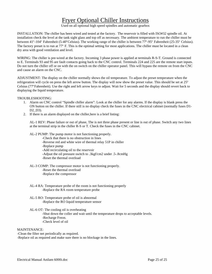
Fryer Optional Chiller Instructions Used on all optional high speed spindles and automatic gearbox
INSTALLATION: The chiller has been wired and tested at the factory. The reservoir is filled with ISO#32 spindle oil. At installation check the level at the tank sight glass and top off as necessary. The ambient temperature to run the chiller must be between 41°-104° Fahrenheit (5-40°Celsius). The working range of the chiller is between 77°-95° Fahrenheit (25-35° Celsius). The factory preset is to run at 77° F. This is the optimal setting for most applications. The chiller must be located in a clean dry area with good ventilation and level. WIRING: The chiller is pre-wired at the factory. Incoming 3 phase power is applied at terminals R-S-T. Ground is connected to E. Terminals 93 and 95 are fault contacts going back to the CNC control. Terminals 224 and 225 are the remote start inputs. Do not turn the chiller off or on with the on switch on the chiller operator panel. This will bypass the remote on from the CNC and cause an alarm on the CNC. ADJUSTMENT: The display on the chiller normally shows the oil temperature. To adjust the preset temperature when the refrigeration will cycle on press the left arrow button. The display will now show the preset value. This should be set at 25° Celsius (77°Fahrenheit). Use the right and left arrow keys to adjust. Wait for 5 seconds and the display should revert back to displaying the liquid temperature. TROUBLESHOOTING:
1. Alarm on CNC control “Spindle chiller alarm”: Look at the chiller for any alarms. If the display is blank press the ON button on the chiller. If there still is no display check the fuses in the CNC electrical cabinet (normally fuses D1-D2_D3).
2. If there is an alarm displayed on the chiller,here is a brief listing: AL-1 REV: Phase failure or out of phase, The is not three phase present or line is out of phase. Switch any two lines at the terminal strip in the chiller R-S or T. Check the fuses in the CNC cabinet. AL-2 PUMP: The pump motor is not functioning properly. -Check that there is no obstruction in lines
-Reverse red and white wire of thermal relay 51P in chiller -Replace pump -Add recirculating oil to the reservoir -Adjsut the oil pressure switch to .3kgf/cm2 under .5-.8cmHg -Reset the thermal overload
AL-3 COMP: The compressor motor is not functioning properly.
-Reset the thermal overload -Replace the compressor
AL-4 RA: Temperature probe of the room is not functioning properly
-Replace the RA room temperature probe
AL-5 RO: Temperature probe of oil is abnormal -Replace the RO liquid temperature sensor
AL-6 OT: The cooling oil is overheating -Shut down the coller and wait until the temperature drops to acceptable levels.
-Recharge Freon. -Check level of oil
MAINTENANCE: -Clean the filter net periodically as required. -Replace oil as required and make sure there is no blockage in the lines.