National Aeronautics and Space Administration Fuel Actuator Development and Testing Fuel Actuator Development and Testing Joseph R. Saus John DeLaat NASA GRC, Controls and Dynamics Branch Dr Clarence T Chang Dr . Clarence T . Chang NASA GRC, Combustion Branch Daniel R. Vrnak NASA GRC, Propulsion and Control Systems Engineering Branch Supported by the NASA Supersonics and NASA ERA Programs 3 rd NASA GRC Propulsion Control and Diagnostics Workshop February 28 – March1, 2012, Cleveland, Ohio www.nasa.gov 1
Transcript
National Aeronautics and Space Administration
Fuel Actuator Development and TestingFuel Actuator Development and Testing
Joseph R. SausJohn DeLaatNASA GRC, Controls and Dynamics Branch
Dr Clarence T ChangDr. Clarence T. ChangNASA GRC, Combustion Branch
Daniel R. VrnakNASA GRC, Propulsion and Control Systems Engineering Branch
Supported by the NASA Supersonicsand NASA ERA Programsg
3rd NASA GRC Propulsion Control and Diagnostics WorkshopFebruary 28 – March1, 2012, Cleveland, Ohio
www.nasa.gov 1
National Aeronautics and Space Administration
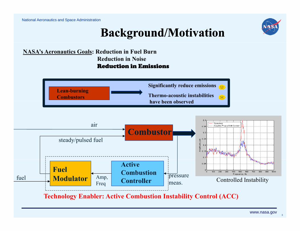
Background/Motivation
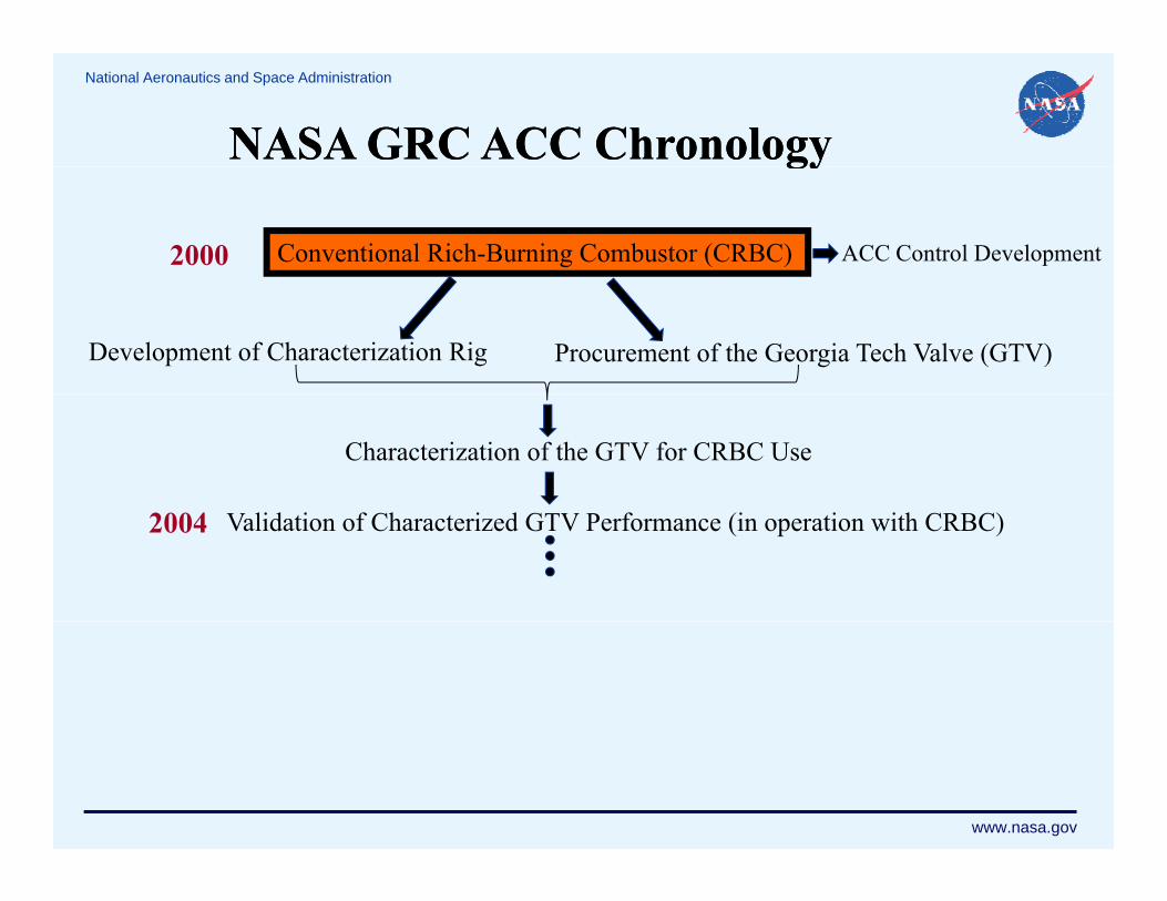
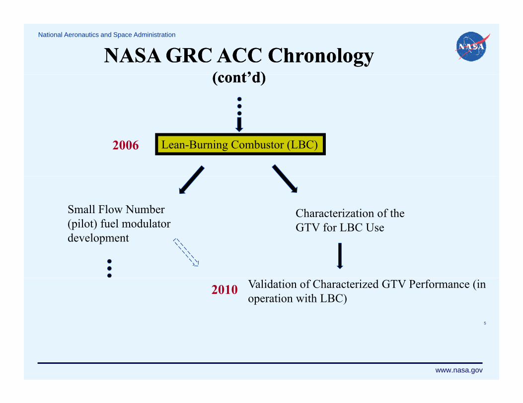
NASA GRC Active Combustion Control Research Program Chronology
B i f D i i f NASA GRC’ Hi h B d id h (HB) F l M d lBrief Description of NASA GRC’s High Bandwidth (HB) Fuel Modulator Characterization Capabilities
Conventional Rich-Burn Combustor ApplicationSpecification/Procurement of a HB Fuel Modulator (GTV)Specification/Procurement of a HB Fuel Modulator (GTV)Characterization/Validation Results
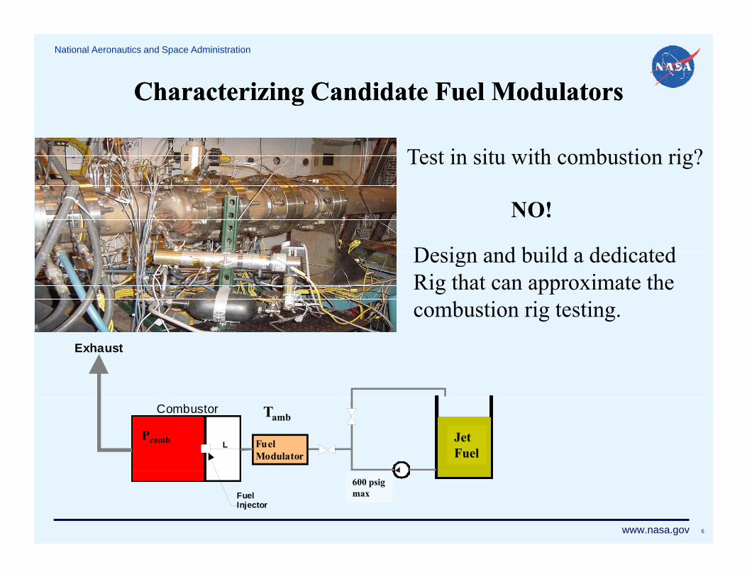
Design and build a dedicatedDesign and build a dedicatedRig that can approximate thecombustion rig testing.
Exhaust
Tamb
FuelModulator
Combustor
L JET AP4Pcomb Jet
Fuel
www.nasa.gov 6
600 psig
FuelInjector
600 psigmax
National Aeronautics and Space Administration
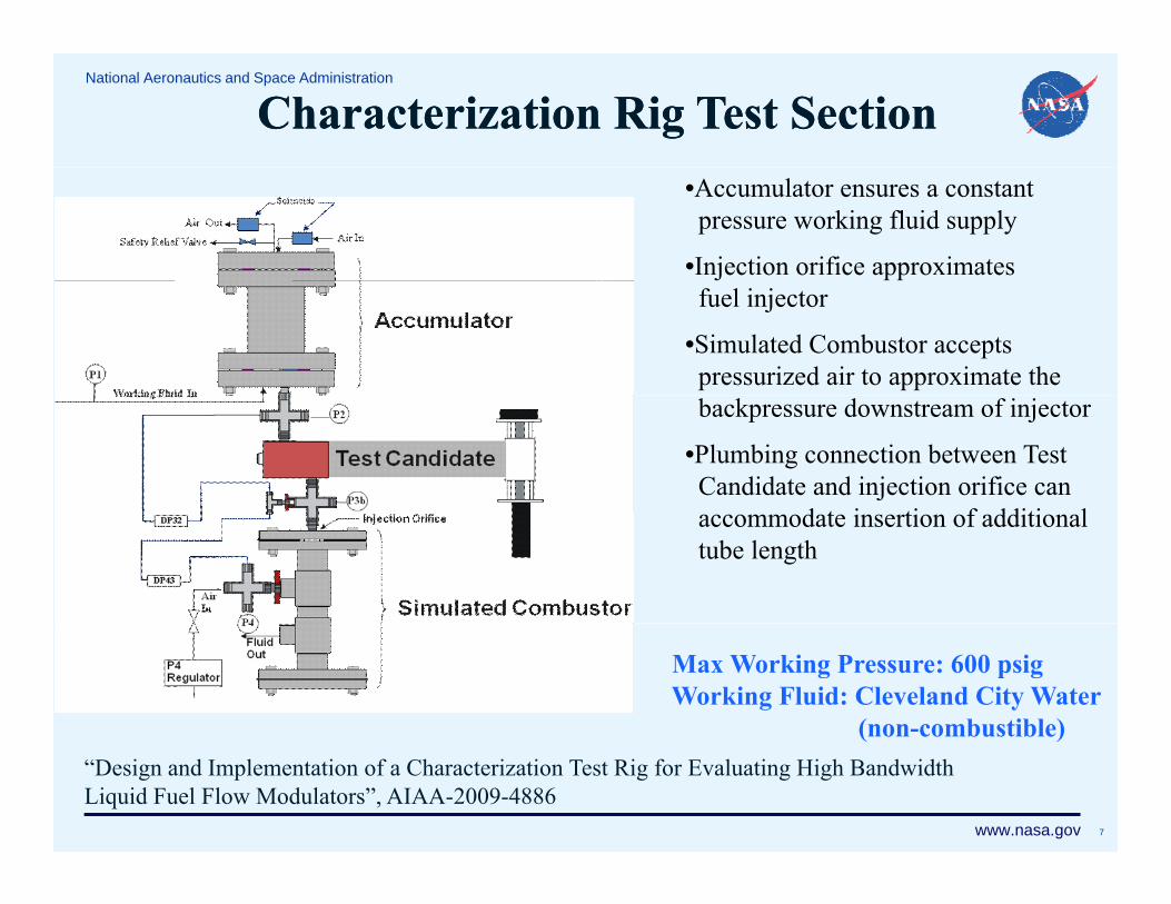
Characterization Rig Test SectionCharacterization Rig Test Section•Accumulator ensures a constantpressure working fluid supply
•Injection orifice approximates fuel injector
•Simulated Combustor acceptspressurized air to approximate thebackpressure downstream of injector
•Plumbing connection between TestCandidate and injection orifice can
d i i f ddi i laccommodate insertion of additionaltube length
Max Working Pressure: 600 psigWorking Fluid: Cleveland City Water
(non-combustible)
www.nasa.gov 7
( )“Design and Implementation of a Characterization Test Rig for Evaluating High BandwidthLiquid Fuel Flow Modulators”, AIAA-2009-4886
National Aeronautics and Space Administration TestingTestingProcedure/Tests
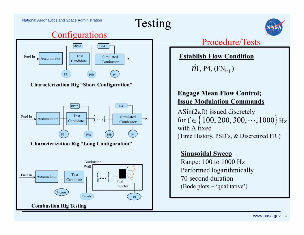
Configurations
Establish Flow Condition
m , P4, (FNinj )
TestCandidateAccumulatorFuel In
DP32
SimulatedCombustor
DP43Procedure/Tests
Engage Mean Flow Control;Issue Modulation Commands
P2
Characterization Rig “Short Configuration”
P3b P4
Issue Modulation CommandsASin(2πft) issued discretelyforwith A fixed
1000 , 300, 200, 100,f Hz…TestCandidateAccumulatorFuel In
DP32
SimulatedCombustor
DP43
(Time History, PSD’s, & Discretized FR )
Sinusoidal SweepRange: 100 to 1000 Hz
Characterization Rig “Long Configuration”
P3aP2 P3b P4
Combustor Range: 100 to 1000 HzPerformed logarithmically70 second duration(Bode plots – ‘qualitative’)
TestCandidate
AccumulatorFuel In …
CombustorWall
FuelInjector
P t
www.nasa.gov 8
Combustion Rig Testing
PvdnstrPvupstr
P4
National Aeronautics and Space Administration
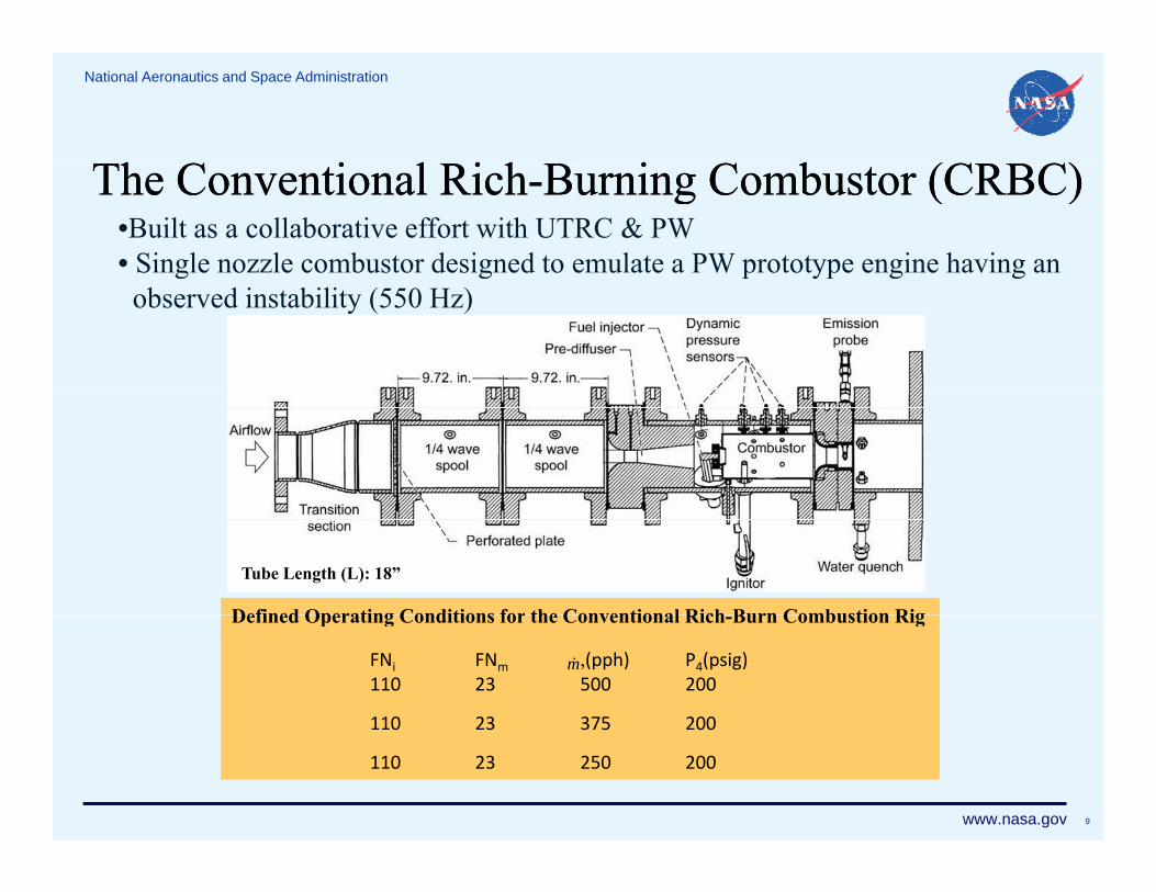
Th C i l Ri hTh C i l Ri h B i C b (CRBC)B i C b (CRBC)The Conventional RichThe Conventional Rich--Burning Combustor (CRBC)Burning Combustor (CRBC)•Built as a collaborative effort with UTRC & PW• Single nozzle combustor designed to emulate a PW prototype engine having ang g p yp g gobserved instability (550 Hz)
Defined Operating Conditions for the Conventional Rich Burn Combustion Rig
Tube Length (L): 18”
Defined Operating Conditions for the Conventional Rich-Burn Combustion Rig
FNi FNm ,(pph) P4(psig)110 23 500 200
110 23 375 200
m
www.nasa.gov 9
110 23 375 200
110 23 250 200
National Aeronautics and Space Administration
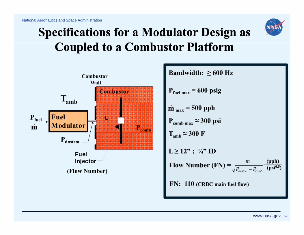
Specifications for a Modulator Design as Specifications for a Modulator Design as C l d t C b t Pl tfC l d t C b t Pl tf
Bandwidth: ≥ 600 Hz
Coupled to a Combustor PlatformCoupled to a Combustor Platform
Bandwidth: ≥ 600 Hz
Pfuel max = 600 psigCombustorTamb
CombustorWall
max = 500 pph
Pcomb max ≈ 300 psi
T ≈ 300 FPcombm
Pfuel
ambm
FuelModulator
L
Tamb ≈ 300 F
L ≥ 12” ; ¼” IDm
Pdnstrm
(pph)FuelInjector
(Flow Number)Flow Number (FN) =
combdnstrm PPm
FN: 110 (CRBC main fuel flow)
(pph)(psi0.5)
Injector
www.nasa.gov 10
National Aeronautics and Space Administration
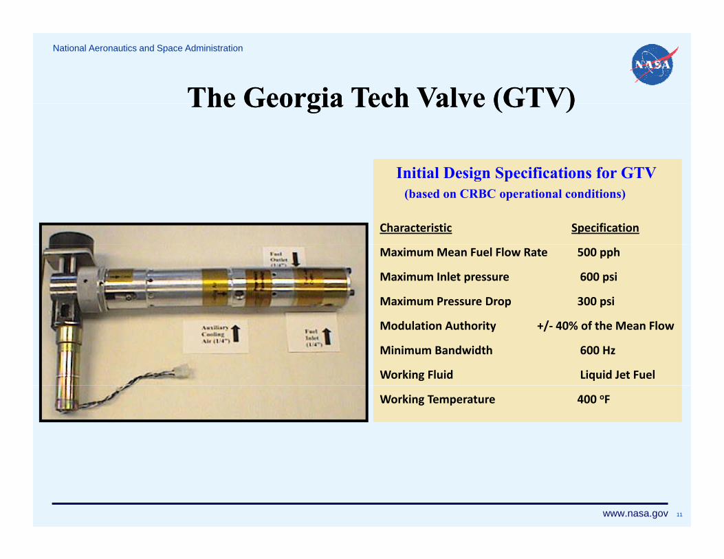
The Georgia Tech Valve (GTV)The Georgia Tech Valve (GTV)
Initial Design Specifications for GTV
The Georgia Tech Valve (GTV)The Georgia Tech Valve (GTV)
Initial Design Specifications for GTV(based on CRBC operational conditions)
Characteristic Specification
Maximum Mean Fuel Flow Rate 500 pph
Maximum Inlet pressure 600 psi
Maximum Pressure Drop 300 psi
Modulation Authority +/‐ 40% of the Mean Flow
Minimum Bandwidth 600 Hz
Working Fluid Liquid Jet Fuel
Working Temperature 400 oF
www.nasa.gov 11
National Aeronautics and Space Administration
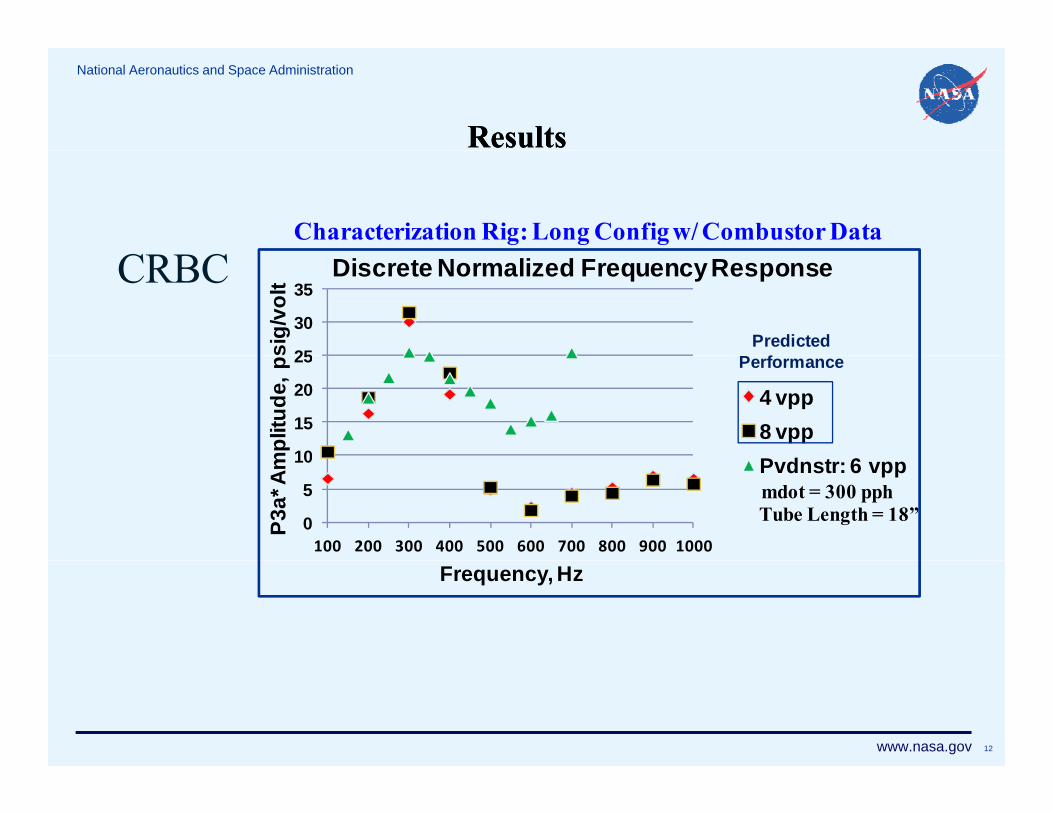
ResultsResults
Characterization Rig: Long Config w/ Combustor Data
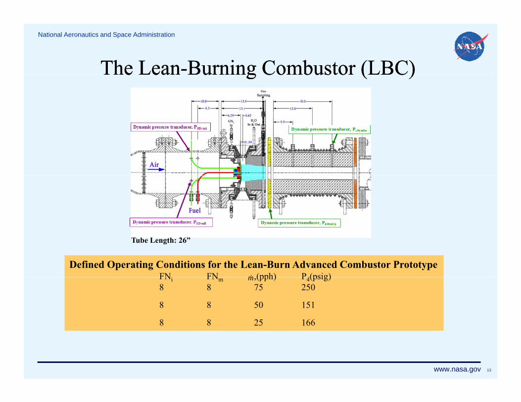
Defined Operating Conditions for the Lean-Burn Advanced Combustor PrototypeFNi FN (pph) P (psig)m
Tube Length: 26”
FNi FNm ,(pph) P4(psig)8 8 75 250
8 8 50 151
8 8 25 166
m
www.nasa.gov 13
National Aeronautics and Space Administration
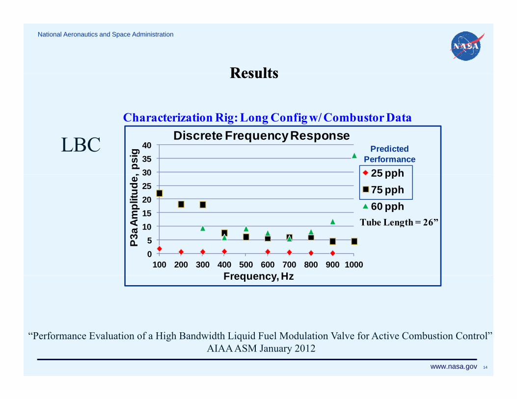
ResultsResultsResultsResults
Characterization Rig: Long Config w/ Combustor Data
303540
, psi
gDiscrete Frequency Response
25 pph
LBC Predicted Performance
Tube Length = 26”1015202530
Ampl
itude
, 25 pph75 pph60 pph
Tube Length 26
05
10
100 200 300 400 500 600 700 800 900 1000
P3a A
Frequency HzFrequency, Hz
www.nasa.gov 14
“Performance Evaluation of a High Bandwidth Liquid Fuel Modulation Valve for Active Combustion Control”AIAA ASM January 2012
National Aeronautics and Space Administration
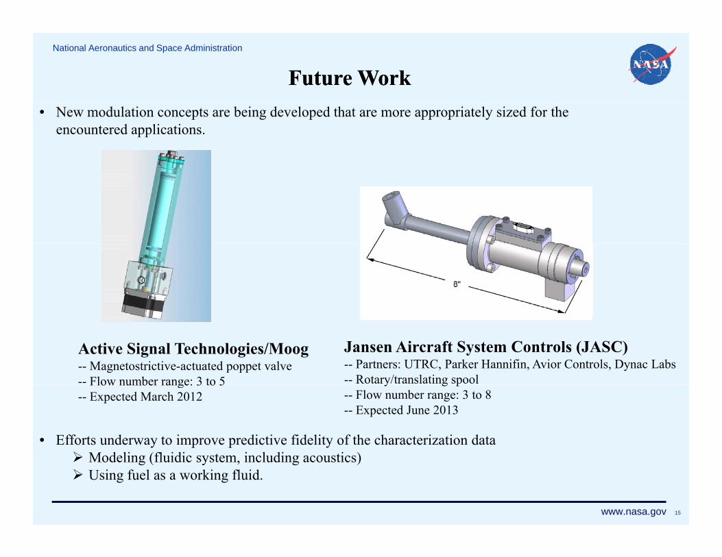
Future Future WorkWork• New modulation concepts are being developed that are more appropriately sized for the
encountered applications.
Active Signal Technologies/Moog-- Magnetostrictive-actuated poppet valve-- Flow number range: 3 to 5
Jansen Aircraft System Controls (JASC)-- Partners: UTRC, Parker Hannifin, Avior Controls, Dynac Labs-- Rotary/translating spoolFlow number range: 3 to 5
-- Expected March 2012y g p
-- Flow number range: 3 to 8-- Expected June 2013
• Efforts underway to improve predictive fidelity of the characterization data M d li (fl idi t i l di ti )
www.nasa.gov 15
Modeling (fluidic system, including acoustics) Using fuel as a working fluid.
National Aeronautics and Space Administration
ConclusionsConclusions• Characterization rig designed and developed for evaluating high bandwidth fuel modulators
• The Georgia Tech Valve (GTV) was evaluated for use as a fuel modulator for 2 distinct b t l tfcombustor platforms characterization and CRBC data agreed well; good authority predicted, success was
achieved. characterization and LBC data agreed well for middle frequencies; poor performance
di t d f tt i dpredicted, poor performance attained.
• Several fuel modulator concepts for lean-burn (pilot) application are under development
• The characterization rig will be used to screen the performance of these concepts prior to use in combustion testing
AcknowledgementAcknowledgementThe authors wish to acknowledge Dr. Daniel Paxson for his consultation on issues surrounding theoptimization of the GTV for off-nominal design operation and for his modeling efforts that supported ouractive combustion control research.