64
• Fuel Dispensing Stations • Wash areas • Car parks • Roads • Industrial Activities FRANCEAUX Oil Separators RAINWATER TREATMENT

• Fuel Dispensing Stations• Wash areas• Car parks• Roads• Industrial Activities
FRANCeAUX oil separators
RAINWAteR tReAtMeNt

2
10 rue Richedoux 50480 SAINTE-MÈRE-ÉGLISE – FRANCE – Tél. +33 (0)2 33 95 88 00 – Fax +33 (0)2 33 21 50 75www.simop.com – e-mail : [email protected] document does not form part of any contract. The data is provided as an indication and may be changed without notice.
SIMOP
WHY CHOOSING SIMOP ?
35 YEARS OF RESEARCH AND DEVELOPMENT !By choosing SIMOP, you will choose a strong business leader with 35 years of
experience and an international reputation. Our offi ce, impregnated with
a strong spirit of innovation, is constantly at the forefront of new techniques
and technologies. The strength of our research and development allows us
to continually evolve existing products launched on the market regularly
which have reliable and sustainable solutions which contribute to improve
the environment and its patented processes.
LARGE STOCKS AVAILABLE > STARTING IN 72H !
4 INDUSTRIAL SITES FOR GREATER RESPONSIVENESS !Our French production is
spread over four sites to ensure manufacturing closest to you, and
delivery within 5 days for most of our reference standards.
Upon receipt of order, your separator leaves our production site
within 72 hours.BORDEAUX
BOURG-DE-PÉAGE
LE HAM
MONTDIDIER

10 rue Richedoux 50480 SAINTE-MÈRE-ÉGLISE – FRANCE – Tél. +33 (0)2 33 95 88 00 – Fax +33 (0)2 33 21 50 75www.simop.com – e-mail : [email protected] non contractuel. Les cotes (en mm) sont données à titre indicatif et peuvent être modifi ées sans préavis.
SIMOP1
SummaryTechnical Sheets
REF. SIMOP REF. FRANCEAUX PAGEPRESENTATION .................................................................................................................................................................................. 2
SELECTION GUIDE ............................................................................................................................................................................ 4
OIL SEPARATORS PAINteD steeLNF 5 MG/L V100 SILT STORAGE MANHOLE ................................................................................... 4730 ................MACKNF ........................ 11NF 5 MG /L V100 SILT STORAGE WITHOUT PROTECTION ................................................................ 4731 ...............MACKNF ........................ 12NF 5 MG/L V100 SILT STORAGE BYPASS MANHOLE PAINTED STEEL ................................................ 4732 ................PASSNF ......................... 13NF 5 MG/L V100 SILT STORAGE BYPASS WITHOUT PROTECTION PAINTED STEEL .............................. 4733 ................PASSNF ......................... 14CE 5 MG/L V100 SILT STORAGE MANHOLE ................................................................................... 4804 ................MACK ............................ 15CE 5 MG/L V100 SILT STORAGE WITHOUT PROTECTION ................................................................ 4805 ................MACK-AT........................ 16CE 5 MG/L V300 SILT STORAGE MANHOLE ................................................................................... 4808 ................LAVK ............................. 17CE 5 MG/L V300 SILT STORAGE WITHOUT PROTECTION ................................................................. 4809 ................LAVK-AT ......................... 18CE 5 MG/L V100 SILT STORAGE BYPASS MANHOLE ....................................................................... 4810 ................PASSK ........................... 19CE 5 MG/L V100 SILT STORAGE BYPASS WITHOUT PROTECTION ..................................................... 4811 ................PASK-AT ......................... 20CE 5 MG/L V100 SILT STORAGE WITH A COMPARTMENT FIT FOR A PUMPING STATION ...................... 4816 ................FOSKAT .......................... 21/22
OIL SEPARATORS PoLYetHYLeNeCE 5 MG/L V100 SILT STORAGE FROM 1.5 TO 15 L/S .................................................................... 6645 ................NPBCKA/NPBCK ............. 23CE 5 MG/L V100 SILT STORAGE FROM 20 TO 30 L/S .................................................................... 6647 ................NPBCKA/NPBCK ............. 24CE 5 MG/L V100 SILT STORAGE AND BYPASS FROM 3 TO 15 L/S .................................................... 6649 ...............DOKAC/DOK ................... 25CE 5 MG/L V100 SILT STORAGE AND BYPASS FROM 20 TO 30 L/S .................................................. 6648 ................DOKAC/DOK ................... 26CE 5 MG/L V200 SILT STORAGE ................................................................................................... 6644 ................- ................................... 27
OIL SEPARATORS MADe CUstoM steeL AND GRPCE 5 MG/L WITH SILT STORAGE / STEEL / FLOW > 50 L/S .............................................................. 4918 ................IA .................................. 28CE 5 MG/L WITH SILT STORAGE / BYPASS / STEEL / FLOW > 50 L/S ................................................ 4920 ................IACD .............................. 29CE 5 MG/L WITH SILT STORAGE / GRP / FLOW > 50 L/S ................................................................. 6668 ................IAPRV ............................ 30CE 5 MG/L WITH SILT STORAGE / GRP / BYPASS / FLOW > 50 L/S ................................................... 6669 ................IADPRV .......................... 31
LEVEL ALARMSSELECTION TABLE .................................................................................................................................................................................... 32OIL LEVEL ALARM POWERED BY A SOLAR PANEL .......................................................................... 4981 ................ALARME ......................... 33OIL LEVEL ALARM ....................................................................................................................... 4982 ................ALARME ......................... 34SLUDGE LEVEL ALARM ................................................................................................................ 4978 ................ALARM2 ......................... 35ALARM DETECTING OVERFLOW ................................................................................................... 4979 ................ALARM3 ......................... 36BOX OR JUNCTION SLEEVE, CABLE FOR OIL ALARM ATEX ............................................................... 4977 ................BMJ .............................. 37
ACCESSORIESACCESSORIES FOR STEEL OIL SEPARATORS .................................................................................. 4984 ................RH ................................ 38ADJUSTABLE EXTENSION SHAFT FOR POLYETHYLENE OIL SEPARATORS ........................................... 6069 ................RHPEH .......................... 39ANCHORING STRAPS FOR OIL SEPARATORS .................................................................................. 6394 ................CEINT ............................ 40SLUDGE EXTRACTION DEVICE ...................................................................................................... 4980 ................KIT-ASPI ......................... 41OIL BELT TRANSFER ................................................................................................................... 4988 ................CAPT ............................. 42EXTERNAL CATHODIC PROTECTION .............................................................................................. 4985 ................ANODE .......................... 43GRAVEL FILTER DRAIN WITH FIREWALL DEVICE ............................................................................. 4992 ................AVCF ............................. 44/45
INSTALLATION INSTRUCTIONSPARALLELIPEDIC OIL SEPARATOR WITH MANHOLE ......................................................................... P039 ...............- ................................... 46STEEL PARALLELIPEDIC OIL SEPARATOR WITH STEEL ADJUSTABLE EXTENSION SHAFT ........................... P040 ................- ................................... 47OIL SEPARATOR OF THE POLYETHYLENE RANGE ............................................................................ P041 ................- ................................... 48POLYETHYLENE OIL SEPARATOR TO BE BURIED ............................................................................. P060 ................- ................................... 49POLYETHYLENE OIL SEPARATOR ON GROUND WITH A WATER TABLE ............................................... P072 ................- ................................... 50/51ANH22/14320 AND ANH22/15200 ALARMS FOR STEEL OIL SEPARATORS ....................................... P083 ................APHA..............................52ANH22/14320 AND ANH22/15200 ALARMS FOR POLYETHYLENE OIL SEPARATORS ......................... P084 ................APHP ............................ 53
GENERAL MAINTENANCE INSTRUCTIONS
POLYETHYLENE OIL SEPARATOR < 30 L/S .................................................................................... E101 ................- ................................... 54/58

10 rue Richedoux 50480 SAINTE-MÈRE-ÉGLISE – FRANCE – Tél. +33 (0)2 33 95 88 00 – Fax +33 (0)2 33 21 50 75www.simop.com – e-mail : [email protected] non contractuel. Les cotes (en mm) sont données à titre indicatif et peuvent être modifi ées sans préavis.
SIMOP2
REMINDER: oil separators must bear the CE marking in accordance with the Ministerial Decree dated January 27th 2006 and Annex ZA of the standard NF EN 858-1. Unless special dispensation from the local authorities, this order also makes mandatory oil level alarm as additional equipment. The Environmental Code prohibits the discharge of lubricants, new or spent oils into surface waters, groundwater or in the street. Service stations, repair shops, washing areas, car parks must be equipped with an oil separator preceded by a débourbeur. The sludge, often directly integrated to the separator, holds heavy materials from the raw water, then the separator trap the suspended oils from the collected runoff water.
A MULTI-MATERIAL PRODUCTIONSimop offers a complete range of oil separators in steel, polyester and polyethylene.Their production uses different technologies to meet your needs.
PolyethyleneSimop has 35 years of experience in the manufacture of rotational molding. Our industrial allows us to manufacture the larger monobloc parts in Europe (35 m3). This ensures easy implementation and maintenance, perfect sealing of our devices and has the advantage of being recyclable.
GUARANTEE20 YEARS
STABLE MATERIAL
Rotomolded partRotomolding
SeparatorFilament winding
PolyesterOur method, based on the principle of fi lament winding, fully automated, provides continuity of production with a perfect control of the fi nished product and optimization of mechanical strength.
GUARANTEE20 YEARSAGAINST
CORROSION
SteelProduction is subject to quality control and strict traceability from the matter to the fi nished product to shipping : all production operations are traced. Simop has a fully automated grit blasting unit and a paint booth integrated to the production chain which ensure greater consistency in the quality of its products and a coating in accordance with the requirements of standard EN-858-2.
Paint boothGrit blasting unit

10 rue Richedoux 50480 SAINTE-MÈRE-ÉGLISE – FRANCE – Tél. +33 (0)2 33 95 88 00 – Fax +33 (0)2 33 21 50 75www.simop.com – e-mail : [email protected] non contractuel. Les cotes (en mm) sont données à titre indicatif et peuvent être modifi ées sans préavis.
SIMOP3
A COMPANY AT THE CUTTING EDGEOF TECHNOLOGY
The widest range on the market Based on our 35 years of technical and industrial experience, we offer polyethylene, polyester and steel oil separators constituting the multi-line materials the widest on the market.
Cell coalescence deviceOur oil separators are equipped with polypropylene cells (stable material) which ensure the separation between oils and runoff water thanks to the coalescence and a very high specifi c surface. These cells, movable in relation to each other (type fl uidized bed) avoid clogging. In addition, maintenance is very simple (suction truck, easy replacement, shock resistance).
A test base validated CSTB Prior to be launched on the market, All devices are tested on our test base. This base was conducted in accordance with standard NF EN 858-2 and approved by the CSTB in the context of an application for admission to the NF marking (French Standard). Finally, our polyethylene and GRP devices are subject to quality control and their traceability are guaranteed for 20 years against corrosion.
CSTB Validated
A network of effi cient maintenanceHaving our own maintenance network, we can ensure the implementation and maintenance of your equipment throughout France.

10 rue Richedoux 50480 SAINTE-MÈRE-ÉGLISE – FRANCE – Tél. +33 (0)2 33 95 88 00 – Fax +33 (0)2 33 21 50 75www.simop.com – e-mail : [email protected] non contractuel. Les cotes (en mm) sont données à titre indicatif et peuvent être modifi ées sans préavis.
SIMOP4
Calculation of the fl ow rate of rain water
Calculation of the fl ow rate of waste water
CCTP type for oil separators 5mg/l
> STEELThe range of SIMOP steel oil separators is prescribed with text and according to the standards below:Standards: equipment designed in accordance with standard EN858 standard and XP P16451-1/CN-1. CE marking in accordance with EN 858-1. The sepa-rators are available with the following options: overfl ow alarms, sludge and oil alarms, oil belt transfer, sludge suction, external anodes and extension shafts.CCTP type : oil separators with sludge, brand SIMOP or similar, blasted and painted steel type ..... (name of the separator), rejection 5 mg/l at any point in accordance with standard EN858-1, designed according to the standard XP P16 451-1/CN and CE marked, treated fl ow rate ....l / s. Audible and visual SI-MOP alarm of an ATEX standard proposed and provided by the manufacturer. All SIMOP separators may be provided either with total accessibility with extension shafts 125 or 250 KN , either with manhole(s) without lid.
> POLYETHYLENEThe range of SIMOP HDPE oil separators, CE labeled, is prescribed with text and according to the standards below :Standards : Manufactured in accordance with CE standard EN 858-1. The stan-dard is about two types of rejection classes - Class 1: rejection of 5mg/l and Class 2: rejection of 100 mg/l. The separators are available with the following options : overfl ow alarms, sludge and oil alarms, oil belt transfer, sludge suction and extension shafts.CCTP type: oil separator with sludge, brand SIMOP or similar, high density poly-ethylene type ..... (name of the separator), rejection class: ....mg/l at any point in accordance with standard EN 858-1, CE marked, treated fl ow rate ....l/s. Audible and visual SIMOP alarm of an ATEX standard proposed and provided by the ma-nufacturer. All separators SIMOP may be provided either with total accessibility with extension shafts 125 or 250 KN, either with manhole(s) without lid.
Sludge quantity examples of use Mini silt storage
volume
WEAK
• Wastewater containing a small amount of sludge defi ned
• All areas of collecting rainwater where a small amount of sedi-ment is due to traffi c or similar, for example catchments in the parks of petroleum storage and covered fi lling stations.
V100
MEDIUM
• Filling stations, manual car wash areas, parts wash areas
• buses wash sites• Waste water of the garages, car
parks• Power plants, tooling factories
V200
HIGH
• wash areas for construction vehicles, construction machines, agricultural machinery
• wash areas for trucks• automatic car wash areas, for
example rollers, corridors
V300
CHOOSE THE SILT STORAGE VOLUMEIT IS DETERMINED ACCORDING TO THE AMOUNT OF SLUDGE AND USE OF THE SEPARATOR.
What is the risk of oil contaminating the drainage from the site ?
Low risk of contamination or episodic risks of small spills
(roads, car parks,...)
Bypass oil separator required
Choose the separator class
Calculation of the fl ow rate of rain water
Frequent contamination (auto parts stores, petrol
stations, oil storage areas, car wash areas, industrial
sites,...)
Oil separator without by-passrequired
Calculation of the nominal sizeCalculation of the nominal size
Choose the silt storage volume
Choose the separator class
>Storm water may be strictly discharged strictly into the environment.> The waste water must be strictly rejected by the public sewer wastewater.> Mixtures stormwater / wastewater must be discharged into the public sewer wastewater.
In principle, we consider the density is 0.85 and there is not detergent. If there is a detergent presence or if the density is not 0,85, please consult us.
Choose the silt storage volume
CHOOSE THE SEPARATOR CLASS- CLASS 1: 5 MG/L REQUIRED FOR DISCHARGES TO SURFACE WATER DRAINS AND THE WATER ENVIRONMENT. - CLASS 2: 100 MG/L REQUIRED FOR DISCHARGES TO THE PUBLIC SEWER.

10 rue Richedoux 50480 SAINTE-MÈRE-ÉGLISE – FRANCE – Tél. +33 (0)2 33 95 88 00 – Fax +33 (0)2 33 21 50 75www.simop.com – e-mail : [email protected] non contractuel. Les cotes (en mm) sont données à titre indicatif et peuvent être modifi ées sans préavis.
SIMOP5
WASHING AREASUSE AND APPLICATIONSeparators with bypass device (bypass)not suitable for this type of use.
*The fl ow rate to be treated is calculated according to the indications of the Order dated January 7th 2003 on classifi ed installations under 1434.** Example in the absence of detergent and for oils of a density of 0.85.
covered washing area WASHING GUIDEØ20 PIPE, LIGHT VEHICLE
Taps Flow rate to be treated* NS**1 1 l/s 1,5 l/s
2 2 l/s 3 l/s
3 2,7 l/s 3 l/s
4 3,2 l/s 6 l/s
5 3,4 l/s 6 l/s
> 5 + 0,2 l/s and /tap
Piping ø25, HEAVY TRUCKS
Taps Flow rate to be treated * NS**2 3,4 l/s 6 l/s
3 4,6 l/s 6 l/s
4 5,45 l/s 6 l/s
5 5,75 l/s 6 l/s
> 5 + 0,3 l/s and /tap
ROLLERS
Washing Units
Flow rate to be treated * NS**
1 2 l/s 3 l/s
2 4 l/s 6 l/s
3 6 l/s 6 l/s
4 8 l/s 8 l/s
5 10 l/s 10 l/s
High Pressure
Washing Units
Flow rate to be treated * NS**
1 2 l/s 3 l/s
2 3 l/s 3 l/s
3 4 l/s 6 l/s
4 5 l/s 6 l/s
5 6 l/s 6 l/s
not covered washing area
1 –Search the nominal size (NS) in the table of a cove-red washing area.
2 - Search the nominal size in the table concerning non-covered car parks without bypass.
3 - NS to remember is the more important of the two.
SIMOP range meeting your needs without the possibility of a by-pass
Silt storage Material Treatment Output Size Technical Sheet Page
V100 Steel without bypass 5 mg/l from 1,5 to 50 l/s 4804 with manhole 15
V100 Steel without bypass 5 mg/l from 1,5 to 50 l/s 4805 with frame 16
V100 Steel without bypass 5 mg/l from 3 to 50 l/s 4816 with frame 21/22
V300 Steel without bypass 5 mg/l from 1,5 to 20 l/s 4808 with manhole 17
V300 Steel without bypass 5 mg/l from 1,5 to 20 l/s 4809 with frame 18
V100 PE without bypass 5 mg/l from 1,5 to 15 l/s 6645 23V100 PE without bypass 5 mg/l from 20 to 30 l/s 6647 24V200 PE without bypass 5 mg/l from 3 to 15 l/s 6644 27

10 rue Richedoux 50480 SAINTE-MÈRE-ÉGLISE – FRANCE – Tél. +33 (0)2 33 95 88 00 – Fax +33 (0)2 33 21 50 75www.simop.com – e-mail : [email protected] non contractuel. Les cotes (en mm) sont données à titre indicatif et peuvent être modifi ées sans préavis.
SIMOP6
CAR PARKS, ROADS ANDINDUSTRIAL ACTIVITIESUSE AND APPLICATION
WATER POLLUTION :
The discharge of waste water must be removed by means of a tank (collector) with a separation device or any other system capable of retaining all fl ammable liquids that may be accidentally spread ; a manhole easily accessible, will be out in place before connecting to the network.
The installation will be maintained in good operating condition and cleared of sludge and fl ammable liquids recovered as often as necessary.
Sludges and liquids recovered shall not be thrown into the sewer but delivered to a specialized company that has authorized treatment facilities.
Covered car parkswith the possibilityof a bypassor without the possi-bility of a bypass
Surface area NS**1 000 m2 3 l/s
5 000 m2 6 l/s
8 000 m2 15 l/s
11 000 m2 20 l/s
14 000 m2 25 l/s
For surface areas up to 10 000 m2, the calculation of the fl ow rate in liter/second is based on the region, on the surface area and on the runoff coeffi cient. The failure return period of the network is 10 years. For upper surface areas, contact us.
Non-covered car parks
REGION 1 REGION 2 REGION 3 NS**560 m2 420 m2 330 m2 3 l/s
1110 m2 970 m2 670 m2 6 l/s
1480 m2 1110 m2 890 m2 8 l/s
1850 m2 1390 m2 1110 m2 10 l/s
2780 m2 2080 m2 1670 m2 15 l/s
3700 m2 2780 m2 2220 m2 20 l/s
4630 m2 3472 m2 2777 m2 25 l/s
5555 m2 4166 m2 3333 m2 30 l/s
6481 m2 4861 m2 3888 m2 35 l/s
7407 m2 5555 m2 4444 m2 40 l/s
9260 m2 6944 m2 5555 m2 50 l/s
300 l/s/ha 400 l/s/ha 500 l/s/ha
Pluviometry
maxi surface area
Treated fl ow rate = 20% of the peak fl ow
With bypass possibility
REGION 1 REGION 2 REGION 3 NS**110 m2 80 m2 70 m2 3 l/s
220 m2 170 m2 130 m2 6 l/s
300 m2 220 m2 180 m2 8 l/s
370 m2 280 m2 220 m2 10 l/s
560 m2 420 m2 330 m2 15 l/s
740 m2 560 m2 440 m2 20 l/s
925 m2 694 m2 555 m2 25 l/s
1 111 m2 833 m2 666 m2 30 l/s
1 296 m2 972 m2 777 m2 35 l/s
1 481 m2 1 111 m2 888 m2 40 l/s
1 851 m2 1388 m2 1 111 m2 50 l/s
300 l/s/ha 400 l/s/ha 500 l/s/ha
Pluviometry
maxi surface area
Without possibility of bypass
REGION 1
REGION 2
RÉGION 3
Rainfall in different regions
Industrial ActivitiesCareening, scrap yards, tire industries, waste reception centers, mechanical workshops, steel cutting workshops, power plants, tool factories, auto garages (sewage), ports, airports, cargo areas, processing of building materials (terracotta, stone,...). Separators with bypass are not suitable for this type of use.
RoadsResidential and rural areas, urban centers, landscape basin upstreams, retention basin downstreams (settling) retention basin upstreams (settling).
*The fl ow rate to be treated is calculated according to the indications of the the Order dated January 7th 2003 on classifi ed installations under 1434.** Example in the absence of detergent and for oils of a density of 0.85.

10 rue Richedoux 50480 SAINTE-MÈRE-ÉGLISE – FRANCE – Tél. +33 (0)2 33 95 88 00 – Fax +33 (0)2 33 21 50 75www.simop.com – e-mail : [email protected] non contractuel. Les cotes (en mm) sont données à titre indicatif et peuvent être modifi ées sans préavis.
SIMOP7
CAR PARKS, ROADS ANDINDUSTRIAL ACTIVITIESUSE AND APPLICATION
SIMOP range meeting your needs with the possibility of a bypass
Silt storage Material Treatment Output Size Technical Sheet Page
V100 steel bypass 5 mg/l from 3 to 50 l/s 4810 with manhole 19V100 steel bypass 5 mg/l from 3 to 50 l/s 4811 with frame 20V100 PE bypass 5 mg/l from 3 to 15 l/s 6649 25V100 PE bypass 5 mg/l from 20 to 30 l/s 6648 26
SIMOP range meeting your needs without the possibility of a bypass
Silt storage Material Treatment Output Size Technical Sheet Page
V100 steel without bypass 5 mg/l from 1,5 to 50 l/s 4804 with manhole 15V100 steel without bypass 5 mg/l from 1,5 to 50 l/s 4805 with frame 16V100 steel without bypass 5 mg/l from 3 to 50 l/s 4816 with frame 21/22V300 steel without bypass 5 mg/l from 1,5 to 20 l/s 4808 with manhole 17V300 steel without bypass 5 mg/l from 1,5 to 20 l/s 4809 with frame 18V100 PE without bypass 5 mg/l from 1,5 to 15 l/s 6645 23V100 PE without bypass 5 mg/l from 20 to 30 l/s 6647 24V200 PE without bypass 5 mg/l from 3 to 15 l/s 6644 27

10 rue Richedoux 50480 SAINTE-MÈRE-ÉGLISE – FRANCE – Tél. +33 (0)2 33 95 88 00 – Fax +33 (0)2 33 21 50 75www.simop.com – e-mail : [email protected] non contractuel. Les cotes (en mm) sont données à titre indicatif et peuvent être modifi ées sans préavis.
SIMOP8
PETROL STATIONSUSE AND APPLICATIONSEPARATORS WITH BYPASS DEVICE ARE
NOT SUITABLE FOR THIS TYPE OF USE.
* The fl ow rate to be treated is calculated according to the indications of the the Order dated January 7th 2003 on classifi ed installations under 1434.** Example in the absence of detergent and for oils of a density of 0.85.
Covered car park
Surface Flow rate to be treated* NS**
120 m2 0,75 l/s 1,5 l/s
240 m2 1,5 l/s 1,5 l/s
480 m2 3 l/s 3 l/s
800 m2 5 l/s 5 l/s
Non-covered car park
Surface Flow rate to be treated* NS**
120 m2 1,5 l/s 1,5 l/s
240 m2 3 l/s 3 l/s
480 m2 6 l/s 6 l/s
800 m2 10 l/s 10 l/s
SIMOP range meeting your needs without the possibility of a bypass
Silt storage Material Treatment Output Size Technical Sheet Page
V100 steel without bypass 5 mg/l from 1,5 to 50 l/s 4804 with manhole 15V100 steel without bypass 5 mg/l from1,5 to 50 l/s 4805 with frame 16V100 steel without bypass 5 mg/l from 3 to 50 l/s 4816 with manhole 21/22V300 steel without by pass 5 mg/l from 1,5 to 20 l/s 4808 with frame 17V300 steel without by pass 5 mg/l from 1,5 to 20 l/s 4809 with manhole 18V100 PE without by pass 5 mg/l from 1,5 to 15 l/s 6645 23V100 PE without by pass 5 mg/l from 20 to 30 l/s 6647 24V200 PE without by pass 5 mg/l from 3 to 15 l/s 6644 27

10 rue Richedoux 50480 SAINTE-MÈRE-ÉGLISE – FRANCE – Tél. +33 (0)2 33 95 88 00 – Fax +33 (0)2 33 21 50 75www.simop.com – e-mail : [email protected] non contractuel. Les cotes (en mm) sont données à titre indicatif et peuvent être modifi ées sans préavis.
SIMOP9
ACCESSORIES
Alarms> Audible and visual sludge level alarmThis device can detect if the deposit of sludge formed in the sludge compartment has reached the maximum allowable level without affecting the operation of the unit. Sensor embedded in the device detects the sludge blanket and triggers the alarm.
> Audible and visual oil level alarmThis device can detect the level of oil in the separator before sealing the system. The sensor inside the separator detects the oil / water interface and thus allows the Supervisor to monitor the thickness of the oil layer stored. When the maximum reten-tion level is reached, the alarm sounds. Depending on the selec-ted alarm, please fi nd the reference to order.
> Audible and visual oil level alarm with solar panelThe system control and alarm with solar panel supply is desig-ned for monitoring the thickness of the oil layer or stored sludge level in a separator, when there is no scope of electric line.
Extension shafts (optional)> Device with full accessibilityExtension shafts are available to adjust the frames to the height of the fi nished fl oor and to put in place the devices with a frost protection : the standard extension shafts have heights of 200, 350, 500, 650 and 800 mm. The shims are used to adjust the device’s height up to 150 mm for each preset height and catch a slope laterally and longitudinally of the fi nished fl oor.
Our separators allow the installation of cast iron covers 125 or 250 KN.
> Device with manholeConcrete extension shafts, commercially available, are adaptable to our manholes in accordance with EN476.
Ref. SIMOP : ANH22/14506. Ref. FRANCEAUX : ALARM-HYDRO-SOL-ATEXAudible and visual oil level alarm IP65 powered by solar panelRef. SIMOP : ANH22/14507. Ref. FRANCEAUX : ALARM-HY-SOL-GSM-ATEXAudible and visual oil level alarm IP65 + GSM powered by solar panelRef. SIMOP : ANH22/14320. Réf. FRANCEAUX : ALARM-HYDRO-ATEXAudible and visual oil level alarm IP65.Ref. SIMOP : ANH22/15200. Ref. FRANCEAUX : ALARM-GSM-ATEXAudible and visual oil level alarm IP65 + GSM
Refer to datasheets 4981 and 4982 pages 33 and 34.
The Ministerial Decree of 27 January 2006 mandates an alarm level as additional equipment.SIMOP offers single level alarms and alarms powered by solar panels.
PE extension shafts RH6069
Steel extension shaft
Blanking plate TR4
Refer to data sheets 4984 and 6069 pages 38 and 39.

10 rue Richedoux 50480 SAINTE-MÈRE-ÉGLISE – FRANCE – Tél. +33 (0)2 33 95 88 00 – Fax +33 (0)2 33 21 50 75www.simop.com – e-mail : [email protected] non contractuel. Les cotes (en mm) sont données à titre indicatif et peuvent être modifi ées sans préavis.
SIMOP10
The Services
Thanks to their integrated modems, alarms with GSM are the ideal solution for separators of a remote monitoring center (car parks, tunnel, bridge, airport runways, highways,...).If an alarm is triggered, an SMS is sent via modem to authorized persons.Our assistance takes over and sends an on-site technician which will drain the unit.
The relay can receive up to 3 different sensors among the three existing types :• layer thickness sensor ;• overfl ow sensor ;• sludge level sensor.
For the alarm powered by a solar panel, it is possible to double the number of sensors.
Detection1
Alert2
Treating Infor-mation
3
Intervention4

10 rue Richedoux 50480 SAINTE-MÈRE-ÉGLISE – FRANCE – Tél. +33 (0)2 33 95 88 00 – Fax +33 (0)2 33 21 50 75www.simop.com – e-mail : [email protected] non contractuel. Les cotes (en mm) sont données à titre indicatif et peuvent être modifi ées sans préavis.
SIMOP11
OIL SEPARATOR NF 5 MG / LSILT STORAGE V100 AND MANHOLE COVERSPAINTED STEEL
C1=C-132 mm
4730MACKNF
UseThe Environmental Code prohibits the discharge of lubri-cants, new or spent oils, into surface and/or underground water channels. Petrol stations, car parks, repair shops, washing areas, must be equipped with an oil separator and upstream silt storage.
InstallationRespect the recommendations of the P039 installation instructions on page 46.The device will be buried. In cases of extra load or a back-fi ll of over 50cm, a concrete slab must be cast in order to withstand the strains imposed. Attention to special installa-tion conditions hydromorphic fi eld. Important : pull on the fl oat immediately when refi lling the separator with clean water up to the outlet level, then check that it fl oats correctly on the upper level of the apparatus.Refer to the guidelines of standard NF P16-442 for installa-tion, handling and maintenance information, available from AFNOR.
ProtectionA circular cast iron cover must be provided. Its size (125 KN, 250 KN or 400 KN) will depend on the conditions on site (moving load).
AlarmThe oil level alarm is a mandatory element of additional
equipement, except if a special derogation has been obtained from local authorities. References : ANH22/14320 with power supply ; ANH22/14506 with solar panel.
MaintenanceThe coating of the device must be checked periodically, and if necessary, repaired. The oil level alarm is set off when the separated light liquid/water interface level reaches the maximum recommended oil storage volume. In the ab-sence of control and history, completely drain the unit once a year. Immediately after drainage, re-fi ll the separator with clean water up to the outlet level and check that the fl oat is correctly positioned on the upper level of the apparatus. For more information refer to standards EN 858-2 and NF P 16-442.
Technical Defi nitionThis range of oil separators 5 mg/l is designed to trap hydro-carbons in suspension in the collected water. Zone V100 sludge integrated into the device retains heavy matter. Our devices are in accordance with NF P16-451-1/CN and are NF marked.
Reference Size A B C D E F G H Silt storageVolume
Nb manholes
SH4730/01/00 1,5 890 722 1197 600 720 110 620 160 150 1
SH4730/03/00 3 1020 722 1562 600 760 110 660 250 300 1
SH4730/06/00 6 1220 803 2257 600 920 160 820 240 600 2
Options :ANH22/14320 Oil level alarm with power supply (refer to data sheet 4982 page 34)ANH22/14506 Oil level alarm powered by solar panel (refer to data sheet 4981 page 33)OD4/2102/OTH-80 Extraction device, opening manhole
EN858-1

10 rue Richedoux 50480 SAINTE-MÈRE-ÉGLISE – FRANCE – Tél. +33 (0)2 33 95 88 00 – Fax +33 (0)2 33 21 50 75www.simop.com – e-mail : [email protected] non contractuel. Les cotes (en mm) sont données à titre indicatif et peuvent être modifi ées sans préavis.
SIMOP12
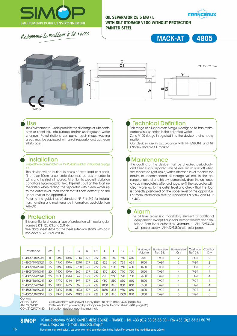
OIL SEPARATOR NF 5 MG / LWITH SILT STORAGE V100 WITHOUT PROTECTIONPAINTED STEEL
Reference Size A B C D1 D2 E F G H Silt storageVolume
Stainless steel Ref. 3 kn
Stainless steel Qty
Cast iron Ref. 3 kn
Cast iron Qty
SH4731/01/RP1L 1,5 890 722 1197 673 577 720 110 620 160 160 TXPL 1 TFPL 1
SH4731/03/RG1L 3 1020 722 1562 922 577 760 110 660 250 300 TXGL 1 TFGL 1
SH4731/06/RP2T 6 1220 803 2257 577 673 920 160 820 240 600 TXPT 2 TFPT 2
Options :ANH22/14320 Oil level alarm with power supply (refer to data sheet 4982 page 34)ANH22/14506 Oil level alarm powered by solar panel (refer to data sheet 4981 page 33)OD4/2102/OT-80 Extraction device, opening manhole
UseThe Environmental Code prohibits the discharge of lubricants, new or spent oils, into surface and/or underground water channels. Petrol stations, car parks, repair shops, washing areas, must be equipped with an oil separator and upstream silt storage.
Technical Defi nitionThis range of oil separators 5 mg/l is designed to trap hydro-carbons in suspension in the collected water. Zone V100 sludge integrated into the device retains heavy matter. Our devices are in accordance with NF P16-451-1/CN and are NF marked.
InstallationRespect the recommendations of the P040 installation instructions on page 47.The device will be buried. In cases of extra load or a back-fi ll of over 50cm, a concrete slab must be cast in order to withstand the strains imposed. Attention to special installation conditions hydromorphic fi eld. Important : pull on the fl oat im-mediately when refi lling the separator with clean water up to the outlet level, then check that it fl oats correctly on the upper level of the apparatus.Refer to the guidelines of standard NF P16-442 for installa-tion, handling and maintenance information, available from AFNOR.
MaintenanceThe coating of the device must be checked periodically, and if necessary, repaired. The oil level alarm is set off when the separated light liquid/water interface level reaches the maximum recommended oil storage volume. In the ab-sence of control and history, completely drain the unit once a year. Immediately after drainage, re-fi ll the separator with clean water up to the outlet level and check that the fl oat is correctly positioned on the upper level of the apparatus. For more information refer to standards EN 858-2 and NF P 16-442.
ProtectionIt is essential to choose a type of protection with rectangular frames 3 KN, 125 KN and 250 KN. See data sheet 4984 for the steel extension shafts with cast iron covers 125 KN or 250 KN.
AlarmsThe oil level alarm is a mandatory element of additional
equipement, except if a special derogation has been ob-tained from local authorities. References : ANH22/14320 with power supply ; ANH22/14506 with solar panel.
4731
EN858-1
C1=C-132 mm
MACKNF

10 rue Richedoux 50480 SAINTE-MÈRE-ÉGLISE – FRANCE – Tél. +33 (0)2 33 95 88 00 – Fax +33 (0)2 33 21 50 75www.simop.com – e-mail : [email protected] non contractuel. Les cotes (en mm) sont données à titre indicatif et peuvent être modifi ées sans préavis.
SIMOP13
OIL SEPARATOR NF 5MG / LWITH SILT STORAGE V100 BYPASS MANHOLE COVERSPAINTED STEEL
Reference Size A B C D E F G H Silt storageVolume Nb Silt storage
SH4732/03/00 3 1020 722 1430 600 760 200 660 160 300 1
SH4732/06/00 6 1220 803 2125 600 920 250 820 150 300 2
Options :ANH22/14320 Oil level alarm with power supply (refer to data sheet 4982 page 34)ANH22/14506 Oil level alarm powered by solar panel (refer to data sheet 4981 page 33)OD4/2102/OTH-80 Extraction device, opening manhole
UseThe Environmental Code prohibits the discharge of lubricants, new or spent oils, into surface and/or underground water channels. Petrol stations, car parks, repair shops, washing areas, must be equipped with an oil separator and upstream silt storage.
Technical Defi nitionThis range of oil separators 5 mg/l is designed to trap hydro-carbons in suspension in the collected water. A bypass located at the inlet box is used to regulate the fl ow (20% of treatment permissible fl ow)Zone V100 sludge integrated into the device retains heavy matter. Our devices are in accordance with NF P16-451-1/CN and are NF marked.
InstallationRespect the recommendations of the P039 installation instructions on page 46.The device will be buried. In cases of extra load or a back-fi ll of over 50cm, a concrete slab must be cast in order to withstand the strains imposed. Attention to special installation conditions hydromorphic fi eld. Important : pull on the fl oat im-mediately when refi lling the separator with clean water up to the outlet level, then check that it fl oats correctly on the upper level of the apparatus.Refer to the guidelines of standard NF P16-442 for installa-tion, handling and maintenance information, available from AFNOR.
MaintenanceThe coating of the device must be checked periodically, and if necessary, repaired. The oil level alarm is set off when the separated light liquid/water interface level reaches the maximum recommended oil storage volume. In the ab-sence of control and history, completely drain the unit once a year. Immediately after drainage, re-fi ll the separator with clean water up to the outlet level and check that the fl oat is correctly positioned on the upper level of the apparatus. For more information refer to standards EN 858-2 and NF P 16-442.
ProtectionA circular cast iron cover must be provided. Its size (125 KN, 250 KN or 400 KN) will depend on the conditions on site (moving load).
AlarmThe oil level alarm is a mandatory element of additional
equipement, except if a special derogation has been ob-tained from local authorities. References : ANH22/14320 with power supply ; ANH22/14506 with solar panel.
4732
EN858-1
C1=C-121 mm
PASSNF

10 rue Richedoux 50480 SAINTE-MÈRE-ÉGLISE – FRANCE – Tél. +33 (0)2 33 95 88 00 – Fax +33 (0)2 33 21 50 75www.simop.com – e-mail : [email protected] non contractuel. Les cotes (en mm) sont données à titre indicatif et peuvent être modifi ées sans préavis.
SIMOP14
OIL SEPARATOR NF 5 MG / LWITH SILT STORAGE V100 BYPASS WITHOUT PROTECTIONPAINTED STEEL
Reference Size A B C D1 D2 E F G H Vol.silt storage
Stainless steel Ref. 3 kn
Stainless steel Qty
Cast iron Ref. 3 kn
Cast iron Qty
SH4731/03/RG1L 3 1020 722 1430 922 577 760 200 660 160 300 TXGL 1 TFGL 1
SH4731/06/RP2T 6 1220 803 2125 577 673 920 250 820 150 600 TXPT 2 TFPT 2
Options :ANH22/14320 Oil level alarm with power supply (refer to data sheet 4982 page 34)ANH22/14506 Oil level alarm powered by solar panel (refer to data sheet 4981 page 33)OD4/2102/OTH-80 Extraction device, opening manhole
UseThe Environmental Code prohibits the discharge of lubricants, new or spent oils, into surface and/or underground water channels. Petrol stations, car parks, repair shops, washing areas, must be equipped with an oil separator and upstream silt storage.
Technical Defi nitionThis range of oil separators 5 mg/l is designed to trap hydro-carbons in suspension in the collected water. A bypass located at the inlet box is used to regulate the fl ow (20% of treatment permissible fl ow)Zone V100 sludge integrated into the device retains heavy matter. Our devices are in accordance with NF P16-451-1/CN and are NF marked.
InstallationRespect the recommendations of the P040 installation instructions on page 47.The device will be buried. In cases of extra load or a back-fi ll of over 50cm, a concrete slab must be cast in order to withstand the strains imposed. Attention to special installation conditions hydromorphic fi eld. Important : pull on the fl oat im-mediately when refi lling the separator with clean water up to the outlet level, then check that it fl oats correctly on the upper level of the apparatus.Refer to the guidelines of standard NF P16-442 for installa-tion, handling and maintenance information, available from AFNOR.
MaintenanceThe coating of the device must be checked periodically, and if necessary, repaired. The oil level alarm is set off when the separated light liquid/water interface level reaches the maximum recommended oil storage volume. In the ab-sence of control and history, completely drain the unit once a year. Immediately after drainage, re-fi ll the separator with clean water up to the outlet level and check that the fl oat is correctly positioned on the upper level of the apparatus. For more information refer to standards EN 858-2 and NF P 16-442.
ProtectionIt is essential to choose a type of protection with rectangular frames 3 KN, 125 KN and 250 KN. See data sheet 4984 for the steel extension shafts with cast iron covers 125 KN or 250 KN.
AlarmThe oil level alarm is a mandatory element of additional
equipement, except if a special derogation has been ob-tained from local authorities. References : ANH22/14320 with power supply ; ANH22/14506 with solar panel.
4733
EN858-1
C1=C-121 mm
PASSNF

10 rue Richedoux 50480 SAINTE-MÈRE-ÉGLISE – FRANCE – Tél. +33 (0)2 33 95 88 00 – Fax +33 (0)2 33 21 50 75www.simop.com – e-mail : [email protected] non contractuel. Les cotes (en mm) sont données à titre indicatif et peuvent être modifi ées sans préavis.
SIMOP15
OIL SEPARATOR CE 5 MG / LWITH SILT STORAGE V100 AND MANHOLE COVERSPAINTED STEEL
Reference Size A B C D E F G H Silt storageVolume
Nb. manholes
SH4804/08/00 8 1360 1076 2115 600 850 160 750 610 800 2
SH4804/10/00 10 1360 1076 2290 600 825 160 725 635 1000 2
SH4804/15/00 15 1360 1076 2780 750 860 200 760 600 1500 2
SH4804/20/00 20 1500 1076 3621 750 870 200 770 730 2000 2
SH4804/25/00 25 1500 1314 3621 950 870 250 770 730 2500 2
SH4804/30/00 30 1710 1314 3971 950 950 250 850 860 3000 2
SH4804/35/00 35 1810 1465 3971 950 1050 315 950 860 3500 2
SH4804/40/00 40 1810 1465 4523 950 1050 315 950 860 4000 2
SH4804/50/00 50 1940 1615 4912 950 1100 315 1000 940 5000 2
Options :ANH22/14320 Oil level alarm with power supply (refer to data sheet 4982 page 34)ANH22/14506 Oil level alarm powered by solar panel (refer to data sheet 4981 page 33)OD4/2102/OTH-80 Extraction device, opening manhole
4804
ProtectionA circular cast iron cover must be provided. Its size (125 KN, 250 KN or 400 KN) will depend on the conditions on site (moving load).
UseThe Environmental Code prohibits the discharge of lubri-cants, new or spent oils, into surface and/or underground water channels. Petrol stations, car parks, repair shops, washing areas, must be equipped with an oil separator and upstream silt storage.
InstallationRespect the recommendations of the P039 installation instructions on page 46.The device will be buried. In cases of extra load or a back-fi ll of over 50cm, a concrete slab must be cast in order to withstand the strains imposed. Attention to special installation conditions hydromorphic fi eld. Important : pull on the fl oat im-mediately when refi lling the separator with clean water up to the outlet level, then check that it fl oats correctly on the upper level of the apparatus.Refer to the guidelines of standard NF P16-442 for installa-tion, handling and maintenance information, available from AFNOR.
Technical Defi nitionThis range of oil separators 5 mg/l is designed to trap hydro-carbons in suspension in the collected water. Zone V100 sludge integrated into the device retains heavy matter. Our devices are in accordance with NF EN858-1 and NF EN858-2 and are CE marked.
AlarmThe oil level alarm is a mandatory element of additional
equipement, except if a special derogation has been obtained from local authorities. References : ANH22/14320 with power supply ; ANH22/14506 with solar panel.
MaintenanceThe coating of the device must be checked periodically, and if necessary, repaired. The oil level alarm is set off when the separated light liquid/water interface level reaches the maximum recommended oil storage volume. In the ab-sence of control and history, completely drain the unit once a year. Immediately after drainage, re-fi ll the separator with clean water up to the outlet level and check that the fl oat is correctly positioned on the upper level of the apparatus. For more information refer to standards EN 858-2 and NF P 16-442.
EN858-1
C1=C-132 mm
MACK
10 rue Richedoux 50480 SAINTE-MÈRE-ÉGLISE – FRANCE – Tél. +33 (0)2 33 95 88 00 – Fax +33 (0)2 33 21 50 75www.simop.com – e-mail : [email protected] non contractuel. Les cotes (en mm) sont données à titre indicatif et peuvent être modifi ées sans préavis.
SIMOP16
C1=C-132 mm
OIL SEPARATOR CE 5 MG / LWITH SILT STORAGE V100 WITHOUT PROTECTIONPAINTED STEEL
Reference Size A B C D1 D2 E F G H Silt storageVolume
Stainless steel Ref. 3 kn
Stainless steel Qty
Cast iron Ref. 3 kn
Cast iron Qty
SH4805/08/RG2T 8 1360 1076 2115 577 922 850 160 750 610 800 TXGT 2 TFGT 2
SH4805/10/RG2T 10 1360 1076 2290 577 922 825 160 725 635 1000 TXGT 2 TFGT 2
SH4805/15/RG3T 15 1360 1076 2780 577 922 860 200 760 600 1500 TXGT 3 TFGT 3
SH4805/20/RG4T 20 1500 1076 3621 577 922 870 200 770 730 2000 TXGT 4 TFGT 4
SH4805/25/RG4T 25 1500 1314 3621 577 922 870 250 770 730 2500 TXGT 4 TFGT 4
SH4805/30/RG4T 30 1710 1314 3971 577 922 950 250 850 860 3000 TXGT 4 TFGT 4
SH4805/35/RG4T 35 1810 1465 3971 577 922 1050 315 950 860 3500 TXGT 4 TFGT 4
SH4805/40/RG4T 40 1810 1465 4523 577 922 1050 315 950 860 4000 TXGT 4 TFGT 4
SH4805/50/RG5T 50 1940 1615 4912 577 922 1100 315 1000 940 5000 TXGT 5 TFGT 5
Options :ANH22/14320 Oil level alarm with power supply (refer to data sheet 4982 page 34)ANH22/14506 Oil level alarm powered by solar panel (refer to data sheet 4981 page 33)OD4/2102/OTH-80 Extraction device, opening manhole
UseThe Environmental Code prohibits the discharge of lubricants, new or spent oils, into surface and/or underground water channels. Petrol stations, car parks, repair shops, washing areas, must be equipped with an oil separator and upstream silt storage.
Technical Defi nitionThis range of oil separators 5 mg/l is designed to trap hydro-carbons in suspension in the collected water. Zone V100 sludge integrated into the device retains heavy matter. Our devices are in accordance with NF EN858-1 and NF EN858-2 and are CE marked.
InstallationRespect the recommendations of the P040 installation instructions on page 47.The device will be buried. In cases of extra load or a back-fi ll of over 50cm, a concrete slab must be cast in order to withstand the strains imposed. Attention to special installation conditions hydromorphic fi eld. Important : pull on the fl oat im-mediately when refi lling the separator with clean water up to the outlet level, then check that it fl oats correctly on the upper level of the apparatus.Refer to the guidelines of standard NF P16-442 for installa-tion, handling and maintenance information, available from AFNOR.
MaintenanceThe coating of the device must be checked periodically, and if necessary, repaired. The oil level alarm is set off when the separated light liquid/water interface level reaches the maximum recommended oil storage volume. In the ab-sence of control and history, completely drain the unit once a year. Immediately after drainage, re-fi ll the separator with clean water up to the outlet level and check that the fl oat is correctly positioned on the upper level of the apparatus. For more information refer to standards EN 858-2 and NF P 16-442.
ProtectionIt is essential to choose a type of protection with rectangular frames 3 KN, 125 KN and 250 KN. See data sheet 4984 for the steel extension shafts with cast iron covers 125 KN or 250 KN.
AlarmThe oil level alarm is a mandatory element of additional
equipement, except if a special derogation has been ob-tained from local authorities. References : ANH22/14320 with power supply ; ANH22/14506 with solar panel.
4805
EN858-1
MACK-AT

10 rue Richedoux 50480 SAINTE-MÈRE-ÉGLISE – FRANCE – Tél. +33 (0)2 33 95 88 00 – Fax +33 (0)2 33 21 50 75www.simop.com – e-mail : [email protected] non contractuel. Les cotes (en mm) sont données à titre indicatif et peuvent être modifi ées sans préavis.
SIMOP17
C1=C-132 mm
OIL SEPARATOR CE 5 MG / LWITH SILT STORAGE V300 AND MANHOLE COVERSPAINTED STEEL
Reference Size A B C D E F G H Silt storageVolume
Nb. manholes
SH4808/01/00 1,5 1220 823 2115 600 800 110 700 520 450 2
SH4808/03/00 3 1360 1076 2115 600 850 110 750 610 900 2
SH4808/06/00 6 1500 1076 3621 750 870 160 770 730 1800 2
SH4808/08/00 8 1500 1314 3621 950 870 160 770 730 2400 2
SH4808/10/00 10 1710 1314 3971 950 950 160 850 860 3000 2
SH4808/15/00 15 1810 1465 4523 950 1050 200 950 860 4500 2
SH4808/20/00 20 1940 1615 4912 950 1100 200 1000 940 6000 2
Options :ANH22/14320 Oil level alarm with power supply (refer to data sheet 4982 page 34)ANH22/14506 Oil level alarm powered by solar panel (refer to data sheet 4981 page 33)OD4/2102/OTH-80 Extraction device, opening manhole
ProtectionA circular cast iron cover must be provided. Its size (125 KN, 250 KN or 400 KN) will depend on the conditions on site (moving load).
UseThe Environmental Code prohibits the discharge of lubricants, new or spent oils, into surface and/or underground water channels. Petrol stations, car parks, repair shops, washing areas, must be equipped with an oil separator and upstream silt storage.
Technical Defi nitionThis range of oil separators 5 mg/l is designed to trap hydro-carbons in suspension in the collected water. Zone V300 sludge integrated into the device retains heavy matter. Our devices are in accordance with NF EN858-1 and NF EN858-2 and are CE marked.
InstallationRespect the recommendations of the P039 installation instructions on page 46.The device will be buried. In cases of extra load or a back-fi ll of over 50cm, a concrete slab must be cast in order to withstand the strains imposed. Attention to special installation conditions hydromorphic fi eld. Important : pull on the fl oat im-mediately when refi lling the separator with clean water up to the outlet level, then check that it fl oats correctly on the upper level of the apparatus.Refer to the guidelines of standard NF P16-442 for installa-tion, handling and maintenance information, available from AFNOR.
MaintenanceThe coating of the device must be checked periodically, and if necessary, repaired. The oil level alarm is set off when the separated light liquid/water interface level reaches the maximum recommended oil storage volume. In the ab-sence of control and history, completely drain the unit once a year. Immediately after drainage, re-fi ll the separator with clean water up to the outlet level and check that the fl oat is correctly positioned on the upper level of the apparatus. For more information refer to standards EN 858-2 and NF P 16-442.
AlarmThe oil level alarm is a mandatory element of additional
equipement, except if a special derogation has been ob-tained from local authorities. References : ANH22/14320 with power supply ; ANH22/14506 with solar panel.
4808
EN858-1
LAVK

10 rue Richedoux 50480 SAINTE-MÈRE-ÉGLISE – FRANCE – Tél. +33 (0)2 33 95 88 00 – Fax +33 (0)2 33 21 50 75www.simop.com – e-mail : [email protected] non contractuel. Les cotes (en mm) sont données à titre indicatif et peuvent être modifi ées sans préavis.
SIMOP18
OIL SEPARATOR CE 5 MG / LWITH SILT STORAGE V300 WITHOUT PROTECTIONPAINTED STEEL
Reference Size A B C D1 D2 E F G H Silt storageVolume
Stainless steel Ref. 3 kn
Stainless steel Qty
Cast iron Ref. 3 kn
Cast iron Qty
SH4809/01/RP2T 1 1220 823 2115 577 673 800 110 700 520 450 TXGL 1 TFPT 1
SH4809/03/RG2T 3 1360 1076 2115 577 922 850 110 750 610 900 TXPT 2 TFGT 2
SH4809/06/RG4T 6 1500 1076 3621 577 922 870 160 770 730 1800 TXGT 2 TFGT 2
SH4809/08/RG4T 8 1500 1314 3621 577 922 870 160 770 730 2400 TXGT 2 TFGT 2
SH4809/10/RG4T 10 1710 1314 3971 577 922 950 160 850 860 3000 TXGT 2 TFGT 2
SH4809/15/RG4T 15 1810 1465 4523 577 922 1050 200 950 860 4500 TXGT 3 TFGT 3
SH4809/20/RG5T 20 1940 1615 4912 577 922 1100 200 1000 940 6000 TXGT 4 TFGT 4
Options :ANH22/14320 Oil level alarm with power supply (refer to data sheet 4982 page 34)ANH22/14506 Oil level alarm powered by solar panel (refer to data sheet 4981 page 33)OD4/2102/OTH-80 Extraction device, opening manhole
UseThe Environmental Code prohibits the discharge of lubricants, new or spent oils, into surface and/or underground water channels. Petrol stations, car parks, repair shops, washing areas, must be equipped with an oil separator and upstream silt storage.
Technical Defi nitionThis range of oil separators 5 mg/l is designed to trap hydro-carbons in suspension in the collected water. Zone V300 sludge integrated into the device retains heavy matter. Our devices are in accordance with NF EN858-1 and NF EN858-2 and are CE marked.
InstallationRespect the recommendations of the P040 installation instructions on page 47.The device will be buried. In cases of extra load or a back-fi ll of over 50cm, a concrete slab must be cast in order to withstand the strains imposed. Attention to special installation conditions hydromorphic fi eld. Important : pull on the fl oat im-mediately when refi lling the separator with clean water up to the outlet level, then check that it fl oats correctly on the upper level of the apparatus.Refer to the guidelines of standard NF P16-442 for installa-tion, handling and maintenance information, available from AFNOR.
MaintenanceThe coating of the device must be checked periodically, and if necessary, repaired. The oil level alarm is set off when the separated light liquid/water interface level reaches the maximum recommended oil storage volume. In the ab-sence of control and history, completely drain the unit once a year. Immediately after drainage, re-fi ll the separator with clean water up to the outlet level and check that the fl oat is correctly positioned on the upper level of the apparatus. For more information refer to standards EN 858-2 and NF P 16-442.
ProtectionIt is essential to choose a type of protection with rectangular frames 3 KN, 125 KN and 250 KN. See data sheet 4984 for the steel extension shafts with cast iron covers 125 KN or 250 KN.
AlarmThe oil level alarm is a mandatory element of additional
equipement, except if a special derogation has been ob-tained from local authorities. References : ANH22/14320 with power supply ; ANH22/14506 with solar panel.
4809
C1=C-132 mm
LAVK-AT
EN858-1

10 rue Richedoux 50480 SAINTE-MÈRE-ÉGLISE – FRANCE – Tél. +33 (0)2 33 95 88 00 – Fax +33 (0)2 33 21 50 75www.simop.com – e-mail : [email protected] non contractuel. Les cotes (en mm) sont données à titre indicatif et peuvent être modifi ées sans préavis.
SIMOP19
OIL SEPARATOR CE 5 MG / LWITH SILT STORAGE V100 BYPASS MANHOLE COVERSPAINTED STEEL
Reference Size A B C D E F G H Silt storageVolume
Nb. manholes
SH4810/08/00 8 1360 1076 2115 600 850 315 750 610 800 2
SH4810/10/00 10 1360 1076 2290 600 825 315 725 635 1000 2
SH4810/15/00 15 1360 1076 2780 750 860 315 760 600 1500 2
SH4810/20/00 20 1500 1076 3621 750 870 315 770 730 2000 2
SH4810/25/00 25 1500 1314 3621 950 870 400 770 730 2500 2
SH4810/30/00 30 1710 1314 3971 950 950 400 850 860 3000 2
SH4810/35/00 35 1810 1465 3971 950 1050 400 950 860 3500 2
SH4810/40/00 40 1810 1465 4523 950 1050 400 950 860 4000 2
SH4810/50/00 50 1940 1615 4912 950 1100 500 1000 940 5000 2
Options :ANH22/14320 Oil level alarm with power supply (refer to data sheet 4982 page 34)ANH22/14506 Oil level alarm powered by solar panel (refer to data sheet 4981 page 33)OD4/2102/OTH-80 Extraction device, opening manhole
UseThe Environmental Code prohibits the discharge of lubricants, new or spent oils, into surface and/or underground water channels. Petrol stations, car parks, repair shops, washing areas, must be equipped with an oil separator and upstream silt storage.
Technical Defi nitionThis range of oil separators 5 mg/l is designed to trap hydro-carbons in suspension in the collected water. Zone V100 sludge integrated into the device retains heavy matter. Our devices are in accordance with NF EN858-1 and NF EN858-2 and are CE marked.
InstallationRespect the recommendations of the P039 installation instructions on page 46.The device will be buried. In cases of extra load or a back-fi ll of over 50cm, a concrete slab must be cast in order to withstand the strains imposed. Attention to special installation conditions hydromorphic fi eld. Important : pull on the fl oat im-mediately when refi lling the separator with clean water up to the outlet level, then check that it fl oats correctly on the upper level of the apparatus.Refer to the guidelines of standard NF P16-442 for installa-tion, handling and maintenance information, available from AFNOR.
MaintenanceThe coating of the device must be checked periodically, and if necessary, repaired. The oil level alarm is set off when the separated light liquid/water interface level reaches the maximum recommended oil storage volume. In the ab-sence of control and history, completely drain the unit once a year. Immediately after drainage, re-fi ll the separator with clean water up to the outlet level and check that the fl oat is correctly positioned on the upper level of the apparatus. For more information refer to standards EN 858-2 and NF P 16-442.
ProtectionA circular cast iron cover must be provided. Its size (125 KN, 250 KN or 400 KN) will depend on the conditions on site (moving load).
AlarmThe oil level alarm is a mandatory element of additional
equipement, except if a special derogation has been ob-tained from local authorities. References : ANH22/14320 with power supply ; ANH22/14506 with solar panel.
4810
C1=C-132 mm
EN858-1
PASSK

10 rue Richedoux 50480 SAINTE-MÈRE-ÉGLISE – FRANCE – Tél. +33 (0)2 33 95 88 00 – Fax +33 (0)2 33 21 50 75www.simop.com – e-mail : [email protected] non contractuel. Les cotes (en mm) sont données à titre indicatif et peuvent être modifi ées sans préavis.
SIMOP20
OIL SEPARATOR CE 5 MG / LWITH SILT STORAGE V100 BYPASS WITHOUT PROTECTIONPAINTED STEEL
Reference Size A B C D1 D2 E F G H Silt storageVolume
Stainless steel Ref. 3 kn
Stainless steel Qty
Cast iron Ref. 3 kn
Cast iron Qty
SH4811/08/RG2T 8 1360 1076 2115 577 922 850 315 750 610 800 TXGT 2 TFGT 2
SH4811/10/RG2T 10 1360 1076 2290 577 922 825 315 725 635 1000 TXGT 2 TFGT 2
SH4811/15/RG3T 15 1360 1076 2780 577 922 860 315 760 600 1500 TXGT 3 TFGT 3
SH4811/20/RG4T 20 1500 1076 3621 577 922 870 315 770 730 2000 TXGT 4 TFGT 4
SH4811/25/RG4T 25 1500 1314 3621 577 922 870 400 770 730 2500 TXGT 4 TFGT 4
SH4811/30/RG4T 30 1710 1314 3971 577 922 950 400 850 860 3000 TXGT 4 TFGT 4
SH4811/35/RG4T 35 1810 1465 3971 577 922 1050 400 950 860 3500 TXGT 4 TFGT 4
SH4811/40/RG4T 40 1810 1465 4523 577 922 1050 400 950 860 4000 TXGT 4 TFGT 4
SH4811/50/RG5T 50 1940 1615 4912 577 922 1100 500 1000 940 5000 TXGT 5 TFGT 5
Options :ANH22/14320 Oil level alarm with power supply (refer to data sheet 4982 page 34)ANH22/14506 Oil level alarm powered by solar panel (refer to data sheet 4981 page 33)OD4/2102/OTH-80 Extraction device, opening manhole
UseThe Environmental Code prohibits the discharge of lubricants, new or spent oils, into surface and/or underground water channels. Surface car parks and roads may be equipped with an oil separator with bypass and upstream silt storage.
Technical Defi nitionThis range of oil separators 5 mg/l is designed to trap hydro-carbons in suspension in the collected water. Zone V100 sludge integrated into the device retains heavy matter. Our devices are in accordance with NF EN858-1 and NF EN858-2 and are CE marked.
InstallationRespect the recommendations of the P040 installation instructions on page 47.The device will be buried. In cases of extra load or a back-fi ll of over 50cm, a concrete slab must be cast in order to withstand the strains imposed. Attention to special installation conditions hydromorphic fi eld. Important : pull on the fl oat im-mediately when refi lling the separator with clean water up to the outlet level, then check that it fl oats correctly on the upper level of the apparatus.Refer to the guidelines of standard NF P16-442 for installa-tion, handling and maintenance information, available from AFNOR.
MaintenanceThe coating of the device must be checked periodically, and if necessary, repaired. The oil level alarm is set off when the separated light liquid/water interface level reaches the maximum recommended oil storage volume. In the ab-sence of control and history, completely drain the unit once a year. Immediately after drainage, re-fi ll the separator with clean water up to the outlet level and check that the fl oat is correctly positioned on the upper level of the apparatus. For more information refer to standards EN 858-2 and NF P 16-442.
ProtectionIt is essential to choose a type of protection with rectangular frames 3 KN, 125 KN and 250 KN. See data sheet 4984 for the steel extension shafts with cast iron covers 125 KN or 250 KN.
AlarmThe oil level alarm is a mandatory element of additional
equipement, except if a special derogation has been obtained from local authorities. References : ANH22/14320 with power supply ; ANH22/14506 with solar panel.
4811
C1=C-132 mm
EN858-1
PASK-AT

10 rue Richedoux 50480 SAINTE-MÈRE-ÉGLISE – FRANCE – Tél. +33 (0)2 33 95 88 00 – Fax +33 (0)2 33 21 50 75www.simop.com – e-mail : [email protected] non contractuel. Les cotes (en mm) sont données à titre indicatif et peuvent être modifi ées sans préavis.
SIMOP21
OIL SEPARATOR CE 5 MG / LWITH SILT STORAGE V100 WITH A COMPARTMENTFIT FOR A PUMPING STATION (NOT INCLUDED)PAINTED STEEL
4816
C1=C-132 mm
EN858-1
FOSKAT
Reference Size A B C D1 D2 E F F1 G H
SH4816/03/RP2T 3 1220 823 2115 577 673 804 110 110 880 340
SH4816/06/RG3T 6 1360 1076 2780 577 922 873 160 160 1005 355
SH4816/10/RG4T 10 1500 1314 3621 577 922 873 160 160 1131 369
SH4816/15/RG4T 15 1810 1465 3971 577 922 1053 200 200 1442 368
Options :ANH22/14320 Oil level alarm with power supply (refer to data sheet 4982 page 34)ANH22/14506 Oil level alarm powered by solar panel (refer to data sheet 4981 page 33)OD4/2102/OTH-80 Extraction device, opening manhole
UseThe Environmental Code prohibits the discharge of lubricants, new or spent oils, into surface and/or underground water channels. Petrol stations, car parks, repair shops, washing areas, must be equipped with an oil separator and upstream silt storage.
Technical Defi nitionThis range of oil separators 5 mg/l is designed to trap hydro-carbons in suspension in the collected water. Zone V100 sludge integrated into the device retains heavy matter.A pumping station is integrated in a separate compartment (contact our research department to choose the pump ac-cording to the fl ow and the height to be lift up.Our devices are in accordance with NF EN858-1 and NF EN858-2 and are CE marked.
InstallationRespect the recommendations of the P040 installation instructions on page 47.The device will be buried. In cases of extra load or a back-fi ll of over 50cm, a concrete slab must be cast in order to withstand the strains imposed. Attention to special installation conditions hydromorphic fi eld. Important : pull on the fl oat im-mediately when refi lling the separator with clean water up to the outlet level, then check that it fl oats correctly on the upper level of the apparatus.Refer to the guidelines of standard NF P16-442 for installa-tion, handling and maintenance information, available from AFNOR.
MaintenanceThe coating of the device must be checked periodically, and if necessary, repaired. The oil level alarm is set off when the separated light liquid/water interface level reaches the maximum recommended oil storage volume. In the ab-sence of control and history, completely drain the unit once a year. Immediately after drainage, re-fi ll the separator with clean water up to the outlet level and check that the fl oat is correctly positioned on the upper level of the apparatus. For more information refer to standards EN 858-2 and NF P 16-442.
ProtectionIt is essential to choose a type of protection with rectangular frames 3 KN, 125 KN and 250 KN. See data sheet 4984 for the steel extension shafts with cast iron covers 125 KN or 250 KN.
AlarmThe oil level alarm is a mandatory element of additional
equipement, except if a special derogation has been ob-tained from local authorities. References : ANH22/14320 with power supply ; ANH22/14506 with solar panel.

10 rue Richedoux 50480 SAINTE-MÈRE-ÉGLISE – FRANCE – Tél. +33 (0)2 33 95 88 00 – Fax +33 (0)2 33 21 50 75www.simop.com – e-mail : [email protected] non contractuel. Les cotes (en mm) sont données à titre indicatif et peuvent être modifi ées sans préavis.
SIMOP22
Help me chooseChoosing devices with 2 pumps allow to increase the life of the pumps. Indeed they operate alternately with a control unit outside the pumping station.
PUMP SELECTION GUIDEFOR OIL SEPARATOR WITH PUMPING STATION1 OR 2 PUMP ON TRIPOD
4816
Pump determination 6 l/s
HEI
GH
T IN
MET
ERS
TO B
E LI
FT U
P (G
H)
109876543210
5 10 15 20 25 30 35 40 45 50 60 70 80 90 100
DISCHARGE LENGTH PVC PRESSURE 80 MM
PP4816/01/06-3 (1 pompes)PP4816/02/06-3 (2 pompes)
PP4816/01/06-2 (1 pompe)PP4816/02/06-2 (2 pompes)
PP4816/01/06-1 (1 pompe)PP4816/02/06-1 (2 pompes)
Pump determination 1.5 l / s
HEI
GH
T IN
MET
ERS
TO B
E LI
FT U
P (G
H)
109876543210
5 10 15 20 25 30 35 40 45 50 60 70 80 90 100
DISCHARGE LENGTH PVC PRESSURE 50 MM
PP4816/01/01-3 (1 pompes)PP4816/02/01-3 (2 pompes)
PP4816/01/01-2 (1 pompe)PP4816/02/01-2 (2 pompes)
PP4816/01/01-1 (1 pompe)PP4816/02/01-1 (2 pompes)
PP4816/01/01-4 (1 pompes)PP4816/02/01-4 (2 pompes)
Pump determination 3 l/s
HEI
GH
T IN
MET
ERS
TO B
E LI
FT U
P (G
H) 10
987
6543210
5 10 15 20 25 30 35 40 45 50 60 70 80 90 100
DISCHARGE LENGTH PVC PRESSURE Ø 65 MM
PP4816/01/03-3 (1 pompes)PP4816/02/03-3 (2 pompes)PP4816/01/03-2 (1 pompe)PP4816/02/03-2 (2 pompes)
PP4816/01/03-1 (1 pompe)PP4816/02/03-1 (2 pompes)
PP4816/01/03-4 (1 pompes)PP4816/02/03-4 (2 pompes)
4816
5 10 15 20 25 30 35 40 45 50 60 70 80 90 100
PP4816/01/06-3 (1 pump)PP4816/02/06-3 (2 pumps)
PP4816/01/06-2 (1 pump)PP4816/02/06-2 (2 pumps)
PP4816/01/06-1 (1 pump)PP4816/02/06-1 (2 pumps)
PP4816/01/01-3 (1 pump)PP4816/02/01-3 (2 pumps)
PP4816/01/01-2 (1 pump)PP4816/02/01-2 (2 pumps)
PP4816/01/01-1 (1 pump)PP4816/02/01-1 (2 pumps)
PP4816/01/01-4 (1 pump)PP4816/02/01-4 (2 pumps)
)
PP4816/01/03-3 (1 pump)PP4816/02/03-3 (2 pumps)PP4816/01/03-2 (1 pump)PP4816/02/03-2 (2 pumps)
PP4816/01/03-1 (1 pump)PP4816/02/03-1 (2 pumps)
PP4816/01/03-4 (1 pump)PP4816/02/03-4 (2 pumps)

10 rue Richedoux 50480 SAINTE-MÈRE-ÉGLISE – FRANCE – Tél. +33 (0)2 33 95 88 00 – Fax +33 (0)2 33 21 50 75www.simop.com – e-mail : [email protected] non contractuel. Les cotes (en mm) sont données à titre indicatif et peuvent être modifi ées sans préavis.
SIMOP23
Operation The operation of the oil separator is based on the se-paration by density difference of insoluble pollutants contained in runoff water.The silt storage compartment settles and traps sus-pended solids (>200µm). The coalescence system, with its large surface area, enables the concentration of free hydrocarbons which are bumping each other. Hy-drocarbons rise then to the surface. The sealing system (shutter) prevents from any risk of hydrocarbon release.
MaintenanceEnsure periodically that the ventilation is not obstructed.The drainage frequency must be adapted to sludge and oil volumes intercepted.It is recommended to drain the device when the sludge level reaches 50% of the useful volume of the silt storage or when hydrocarbons rise 80% of the retention capa-city of the separator (cf. NF P16-442)Take advantage from the drainage to clean the coales-cence and the sealing systems.After each drainage, the device must be fi lled with wa-ter. Also check that the shutter fl eet.
Technical defi nition An oil separator is a device designed to trap and store free hydrocarbons from runoff water. The silt storage unit traps suspended solids (sand, gravel…).These oil separators without by-pass and equipped with a silt storage are designed to treat water from co-vered car parks, petrol stations, garages. For washing areas a complementary silt storage V200 must be pro-vided to obtain a V300 volume.Reminder :The oil level alarm is mandatory as additional piece of equipment.
Advantages • Patented design in accordance with standards : EN 858-1 and
EN 858-2• A 20 year guarantee tank against corrosion• Held in a saline environment• Resists on ground with a water table and/or hydromorphous soils up to outlet level. • Low weight• Easy handling• Removable coalescence and easy maintenance• Easy connections• Devices held in stock
6645
OIL SEPARATORS 5 MG/L WITH SILT STORAGE V100IN POLYETHYLENE
NPBCKA/NPBCKE G
H
A
C
ØD ØD
B
ØF
DEVICE WITH PE MANHOLES
DEVICES WITH PE FRAMES
GH
E
A
C B
D D
ØF
Reference Flow rate to be treated (l/s)
ManholeNb A B C D E Ø F G H Silt storage
Volume (liters)Oil retention
Volume (liters)
SH2/6645/01 1.5 1 970 760 1280 600x690 610 110 510 460 158 35
SH2/6645/01/00 1.5 1 1120 760 1280 600 610 110 510 610 158 35
SH2/6645/03 3 1 1280 760 1410 600x690 820 110 720 560 300 127
SH2/6645/03/00 3 1 1430 760 1410 600 820 110 720 710 300 127
SH2/6645/06 6 1 1580 850 2000 600x690 1010 160 910 670 613 79
SH2/6645/06/00 6 1 1730 850 2000 600 1010 160 910 820 613 79
SH2/6645/08 8 2 1630 940 2220 600x690 1010 160 910 720 841 80
SH2/6645/08/00 8 2 1780 940 2220 600 1010 160 910 870 841 80
SH2/6645/10 10 2 1630 940 2460 600x690 1050 160 950 680 1030 105
SH2/6645/10/00 10 2 1780 940 2460 600 1050 160 950 830 1030 105
SH2/6645/15 15 2 1900 1540 2400 590x1140 1180 200 1080 820 1556 365
SH2/6645/15/00 15 2 2050 1540 2400 750 1180 200 1080 970 1556 365
Options : ANH22/14320 Oil level alarm with power supplyANH22/14506 Oil level alarm powered by a solar panelSNB/14220 Sludge layer sensorRH6069 Adjustable extension shaft in polyethylene for devices SH2/6645/01, SH2/6645/03 and SH2/6645/06RH2/2030 Adjustable extension shaft in polyethylene for devices SH2/6645/15
EN858-1
InstallationRefer to data sheet P072.

10 rue Richedoux 50480 SAINTE-MÈRE-ÉGLISE – FRANCE – Tél. +33 (0)2 33 95 88 00 – Fax +33 (0)2 33 21 50 75www.simop.com – e-mail : [email protected] non contractuel. Les cotes (en mm) sont données à titre indicatif et peuvent être modifi ées sans préavis.
SIMOP24
6647
OperationThe operation of the oil separator is based on the separa-tion by density difference insoluble pollutants contained in the runoff. Compartment allows sludge to settle and trap sus-pended solids (> 200 microns). Coalescence system with its large surface area allows free oil concentrate in promoting their collision. Oil then rise to the surface. The sealing system prevents the risk of the releasing of hydrocarbons.
Technical Defi nitionAn oil separator is a device designed to trap hydrocarbons in suspension in wastewater. It must be preceded by a silt sto-rage unit which retains heavy matter.Oil separators fi tted with a coalescer are perfectly suited to treating water from covered car parks, petrol stations, ga-rages. For washing areas provide a complementary V200 silt storage to obtain a volume of V300.Reminder: The oil level alarm, additional piece of equipment, is mandatory unless special derogation from the local autho-rities.
InstallationSee sheet P060 for installation on page 49.
MaintenancePeriodically to ensure that the ventilation is not obstructed. Frequency must be adapted to drain sludge volumes and hydrocarbon intercepted. It is recommended to drain the appliance when the sludge reaches 50% of the volume of the sludge or oil occupy 80% of the retention capacity of the se-parator (see NF P16-442). Enjoy the drain to clean the coales-cence and the sealing system. After each discharge, the unit must be returned to water. Also check that the shutter fl eet.
Advantages• Designed in accordance with: EN 858-1 and EN 858-2• Tank with a 20 year anti-corrosion warranty• Tested and held in a saline environment• Resists on ground with a water table up to outlet level• Low weight• Easy handling• Removable coalescence and easy maintenance• Easy connections• Devices held in stock
OIL SEPARATOR 5 MG / LWITH SILT STORAGE V100IN POLYETHYLENE
SortieSortie
ReferenceFlow rate
to be treated(l/s)
Nb.manholes A B B1 C C1 D E F G H
Silt storage volume (liters)
Oil retentionVolume (liters)
SH2/6647/20/00 20 1 2030 1946 1330 2829 1532 950 1132 200 1032 998 2074 377
SH2/6647/25/00 25 2 2030 1946 1330 3580 2301 750 / 950 1132 250 1032 998 2561 499
SH2/6647/30/00 30 2 2030 1946 1330 3954 2676 950 1132 250 1032 998 3027 559
Options :ANH22/14320 Oil level alarm with power supply (refer to data sheet 4982 page 34)ANH22/14506 Oil level alarm powered by solar panel (refer to data sheet 4981 page 33)SNB/14220 Sludge layer sensor
EN858-1
NPBCKA/NPBCK 6647
Δ FEE/FES = 100mmEntrée
A
C
C1C1
B
Δ FEE/FES = 100mmEntrée
Sortie
D
E
A
SortieSortie
B1
D
150
F
Sortie
D
150B1
Sortie
A
B1
C
DD
C1C1C1C1
150150
F
E
Δ FEE/FES = 100mmFEE/FES = 100mmFEE/FES = 100mmFEE/FES = 100mmEntréeEntréeEntréeEntrée
SortieSortieSortie
EN858-1
NPBCKA/NPBCK
G
H

10 rue Richedoux 50480 SAINTE-MÈRE-ÉGLISE – FRANCE – Tél. +33 (0)2 33 95 88 00 – Fax +33 (0)2 33 21 50 75www.simop.com – e-mail : [email protected] non contractuel. Les cotes (en mm) sont données à titre indicatif et peuvent être modifi ées sans préavis.
SIMOP25
Advantages• Patented design in accordance with standards : EN 858-1
and EN 858-2• A 20 year guarantee tank against corrosion• Held in a saline environment• Resists on ground with a water table and/or hydromorphous soils up to outlet level.• internal by-pass tube • Low weight• Easy handling• Removable coalescence and easy maintenance• Easy connections• Devices held in stock
DOKAC/DOK
OperationThe operation of the oil separator is based on the separation by density difference of insoluble pollutants contained in runoff water. The bypass system located at the entry box is used to regulate the fl ow (treatment 20% permissible fl ow). The silt storage compartment settles and traps suspended solids (>200µm). The coalescence system, with its large surface area, enables the concentration of free hydrocarbons which are bumping each other. Hydrocarbons rise then to the surface. The sealing system (shutter) prevents from any risk of hydrocarbon release.
Installation Refer to data sheet P072
Technical defi nitionAn oil separator is a device designed to trap and store free hydrocarbons from runoff water. The silt storage unit traps suspended solids (sand, gravel…).These oil separators without by-pass and equipped with a silt storage are designed to treat water from co-vered car parks, petrol stations, garages. For washing areas a complementary silt storage V200 must be pro-vided to obtain a V300 volume.Reminder :The oil level alarm is mandatory as additio-nal piece of equipment.
6649
OIL SEPARATORS 5 MG/L WITH SILT STORAGE V100 AND BY-PASSIN POLYETHYLENE
DEVICE WITH PE FRAME
GH
E
A
C B
D D
ØF
DEVICE WITH PE MANHOLE
E GH
A
C
ØD ØD
B
ØF
Reference Flow rate to be treated (l/s)
ManholeNb A B C D E Ø F G H Silt storage
Volume (liters)Oil retention
Volume (liters)
SH2/6649/03 3 1 1280 760 1410 600x690 820 200 720 560 300 127
SH2/6649/03/00 3 1 1430 760 1410 600 820 200 720 710 300 127
SH2/6649/06 6 1 1580 850 2000 600x690 1010 250 910 670 613 79
SH2/6649/06/00 6 1 1730 850 2000 600 1010 250 910 820 613 79
SH2/6649/08 8 2 1630 940 2220 600x690 1010 315 910 720 841 80
SH2/6649/08/00 8 2 1780 940 2220 600 1010 315 910 870 841 80
SH2/6649/10 10 2 1630 940 2460 600x690 1050 315 950 680 1030 105
SH2/6649/10/00 10 2 1780 940 2460 600 1050 315 950 830 1030 105
SH2/6649/15 15 2 1900 1540 2400 590x1140 1180 315 1080 820 1556 365
SH2/6649/15/00 15 2 2050 1540 2400 750 1180 315 1080 970 1556 365Options : ANH22/14320 Oil level alarm with power supplyANH22/14506 Oil level alarm powered by a solar panelSNB/14220 Sludge layer sensorRH6069 Adjustable extension shaft in polyethylene for devices SH2/6649/03 and SH2/6649/06RH2/2030 Adjustable extension shaft in polyethylene for devices SH2/6649/15
MaintenanceEnsure periodically that the ventilation is not obstruc-ted.The drainage frequency must be adapted to sludge and oil volumes intercepted.It is recommended to drain the device when the sludge level reaches 50% of the useful volume of the silt storage or when hydrocarbons rise 80% of the retention capacity of the separator (cf. NF P16-442)Take advantage from the drainage to clean the coa-lescence and the sealing systems.After each drainage, the device must be fi lled with wa-ter. Also check that the shutter fl eet.
EN858-1

10 rue Richedoux 50480 SAINTE-MÈRE-ÉGLISE – FRANCE – Tél. +33 (0)2 33 95 88 00 – Fax +33 (0)2 33 21 50 75www.simop.com – e-mail : [email protected] non contractuel. Les cotes (en mm) sont données à titre indicatif et peuvent être modifi ées sans préavis.
SIMOP26
6648
OperationThe operation of the oil separator is based on the separation by density difference insoluble pollutants contained in the ru-noff. The bypass system located at the entry box is used to regulate the fl ow (20% of treatment permissible fl ow). Com-partment allows sludge to settle and trap suspended solids (> 200µm). Coalescence system with its large surface area allows free oil concentrate in promoting their collision. Oil then back to the closure system surface.Le avoids any risk of release of hydrocarbons.
Technical Defi nitionAn oil separator is a device designed to trap hydrocarbons in suspension in wastewater. It must be preceded by a silt sto-rage unit which retains heavy matter.Oil separators with bypass fi tted with a coalescer are perfectly suited to treating water from covered car parks, petrol sta-tions, garages. Reminder: The oil level alarm, additional piece of equipment, is mandatory unless special derogation from the local autho-rities.
InstallationSee sheet P060 for installation on page 49.
MaintenancePeriodically to ensure that the ventilation is not obstructed. Frequency must be adapted to drain sludge volumes and hydrocarbon intercepted. It is recommended to drain the appliance when the sludge reaches 50% of the volume of the sludge or oil occupy 80% of the retention capacity of the separator (see NF P16-442). Take advantage of the drain to clean the coalescence and the sealing system. After each discharge, the unit must be returned to water. Also check that the shutter fl eet.
Advantages• Designed in accordance with: EN 858-1 and EN 858-2• Tank with a 20 year anti-corrosion warranty• Tested and held in a saline environment• Resists on ground with a water table up to outlet level• Low weight• Easy handling• Removable coalescence and easy maintenance• Easy connections• Devices held in stock
OIL SEPARATOR 5 MG / LWITH SILT STORAGE V100 AND BY-PASSIN POLYETHYLENE
ReferenceFlow rate
to be treated(l/s)
Allowable fl ow rate (l/s)
Nb. manholes
A B B1 C C1 D E F G HSilt storage
volume (liters)Oil retention
Volume (liters)
SH2/6648/20/00 20 100 1 2030 1946 1330 2829 1532 950 1132 315 1032 998 2074 377
SH2/6648/25/00 25 125 2 2030 1946 1330 3580 2301 750 / 950 1132 400 1032 998 2561 499
SH2/6648/30/00 30 150 2 2030 1946 1330 3954 2676 950 1132 400 1032 998 3027 559
Options :ANH22/14320 Oil level alarm with power supply (refer to data sheet 4982 page 34)ANH22/14506 Oil level alarm powered by solar panel (refer to data sheet 4981 page 33)SNB/14220 Sludge layer sensor
SortieSortie
G
A
B1
C
DD
C1
150
F
H
E
B
Δ FEE/FES = 100mmEntrée
SortieSortie
EN858-1
DOKAC/DOK

10 rue Richedoux 50480 SAINTE-MÈRE-ÉGLISE – FRANCE – Tél. +33 (0)2 33 95 88 00 – Fax +33 (0)2 33 21 50 75www.simop.com – e-mail : [email protected] non contractuel. Les cotes (en mm) sont données à titre indicatif et peuvent être modifi ées sans préavis.
SIMOP27
Features- Retention Capacity : 10 l per l/s.- Treatment Capacity : 3 to15 l/s.- The volume of silt storage is calculated on the basis of 200l per l/s.- Separating output : 99.88% (below to 5 mg/l) at a density of 0.85.
InstallationThe device must be buried in the outside of the building, as close as possible to the place to be treated. The bottom of the hole must be perfectly fl at and covered with 10 cm of sand. The backfi ll must be sand, and in any case with stone, gravel. Fill the device with clean water up and carry out lateral backfi ll at the same time. In case of passing vehicles less than 3 linear meters, overloading, or embankment height greater than 50 cm relative to ground outlet level, a concrete slab must be poured resting on stable ground in order to withs-tand the strains imposed. The covers should be level with the fi nished ground and must remain accessible. Vent pipes must be connected.Option : polyethylene extension shaft (Ref : RH602) of 250mm is available.
OperationThe operation of the oil separator is based on gravity separation of insoluble matters in water. Water full of hydrocarbons enters the device where the plunging wall forced them to descend, the turbulences on surface are so limited. In the central part of the device, hydrocarbons of lower density than water rise to the surface where they are trapped. A security system with a fl oat plugs the outlet pipe when the oil storage capacity has been reached.
Technical Defi nition An oil separator is a device designed to trap hydrocarbons in suspension in wastewater. It must be preceded by a silt storage unit which retains heavy matter. The Environmental Code pro-hibits the discharge into surface and/or underground water of lubricants, new or spent oils. Oil separators fi tted with a coales-cer are perfectly suited to treating water from areas subject to the requirements of Order 261 bis, Section 1434 concerning fl ammable liquids (decree of 07/01/03) (service stations, distri-bution stations fuel, etc.). Each device is provided with a poly-ethylene screw dawn cover. An extraction system for sludge located in the silt storage unit is provided in our devices. The oil level alarm, additional piece of equipment, is mandatory unless special derogation from the local authorities.
6644
OIL SEPARATOR CE 5 MG / LWITH SILT STORAGE V200POLYETHYLENE
Reference Size A BWidth D E F G H Silt storage
VolumeSeparator
Volume
SHDOC2-1-03 3 1220 1600 600 600 110 550 670 656 380
SHDOC2-1-06 6 1550 1930 600 770 160 720 830 1275 850
SHDOC2-1-08 8 1825 1930 600 1020 160 970 855 1730 1150
SHDOC2-1-10 10 1625 2400 600 790 160 740 885 2010 1300
SHDOC2-1-15 15 1975 2400 600 1120 200 1070 905 3020 1750
Options :RH602 Polyethylene screw-on extension shaft – Height 250 mm
1. Vent pipe Ø 1002. Extraction device3. Screw-on frameOPTION4. Extension shaft RH602ANH2 PS Oil level alarm powered by a solar panel
DEVICE WITH PE FRAME
INSTALLATION WITH CONCRETE SLAB(IF THE WATER INLET LEVEL / GROUND LEVEL IS SUPERIOR TO 500 MM OR IF VEHICLES WILL PASS OVER THE AREA LESS THAN 3 LINEAR METERS)
MaintenanceAs soon as the retention capacity is reached, the alarm in-dicates that sludge and hydrocarbons must be removed. In the absence of control and history, completely drain the unit once a year. Immediately after drainage, re-fi ll the se-parator with clean water up to the outlet level and check that the fl oat is correctly positioned on the upper level of the apparatus. For more information refer to standards EN 858-2 and NF P 16-442.
EN858-1

10 rue Richedoux 50480 SAINTE-MÈRE-ÉGLISE – FRANCE – Tél. +33 (0)2 33 95 88 00 – Fax +33 (0)2 33 21 50 75www.simop.com – e-mail : [email protected] non contractuel. Les cotes (en mm) sont données à titre indicatif et peuvent être modifi ées sans préavis.
SIMOP28
4918
OIL SEPARATOR CE 5 MG / LWITH SILT STORAGEFLOW RATE OVER 50 L / SPAINTED STEEL
IA
Technical Defi nition• Separator sized to accommodate fl ow rates greater than
50 l/s.• The cylindrical design is adapted to resist ground pressure
and sizing generating important fl ow rates.• Oil separator, provided with a steel sleeve to the inlet and
to the outlet, sandblasted steel S235JRG2 SA2, 5 and coa-ted with epoxy paint inside and outside in accordance with the standard EN 858, operating in gravity fl ow. It is provided with a silt storage and a polyethylene siphonic partition This set enables to block fl oatings in the silt storage unit and directs the fl ow rate downward.
• The coalescence in the separation zone is for separating oils. The rocking shutter system in polyethylene with a nitrile joint prohibits oil discharge at the outlet.
• Manholes remain accessible in accordance with EN 476.• Marking on the separator made in accordance with EN
858.
Technical Advantages• Sizing made custom => allow adjustment to site conditions.• Sizing Calculation => Warranty for mechanical resistance• Washable coaslescers => Warranty of an easy mainte-
nance• Closing of the shutter by a nitrile joint => Resistant to most
effl uents containing hydrocarbons
Options• Frame designed for a quick installation => Quick installation
on site with anchoring straps• Cathodic Protection => Protection against stray currents• Ladders, aspirations => Easy use
STS typeOil separator 5 mg/l CE marked with silt storage made of steel S235JRG2, sandblasted SA2,5 and provided with an internal /external epoxy coating, FRANCEAUX brand or similar refe-rence SH4918___ with a honeycomb coalescer in polypropy-lene in accordance with EN 858.
ImportantRegular maintenance of this equipment in accordance with EN 858-2 and NF P 16 442 dated November 2007 is required.The System of extension shaft(s) and cover(s) in accordance with EN 124 are not supplied. Become familiar with the installation instructions of steel oil separators.

10 rue Richedoux 50480 SAINTE-MÈRE-ÉGLISE – FRANCE – Tél. +33 (0)2 33 95 88 00 – Fax +33 (0)2 33 21 50 75www.simop.com – e-mail : [email protected] non contractuel. Les cotes (en mm) sont données à titre indicatif et peuvent être modifi ées sans préavis.
SIMOP29
4920
OIL SEPARATOR CE 5 MG / LSILT STORAGE WITH BY-PASS UPSTREAM OR DOWNSTREAMFLOW RATE OVER 50 L / SPAINTED STEEL
IACD
Technical Defi nition• Separator sized to accommodate fl ow rates greater than
50 l/s.• The cylindrical design is adapted to resist ground pressure
and sizing generating important fl ow rates.• Oil separator, provided with a steel sleeve to the inlet and
to the outlet, sandblasted steel S235JRG2 SA2, 5 and coa-ted with epoxy paint inside and outside in accordance with the standard EN 858, operating in gravity fl ow. It is provided with a silt storage and a polyethylene siphonic partition This set enables to block fl oatings in the silt storage unit and directs the fl ow rate downward.
• The coalescence in the separation zone is for separating oils. The rocking shutter system in polyethylene with a ni-trile joint prohibits oil discharge at the outlet. The upstream storm drain outfall directs the fl ow rate to the silt storage unit. Bypass upstream or downstream allows to divert the surplus to the outlet in case of exceptional rainfall event. It also prevents the resuspending of settled sludge.
• Manholes remain accessible in accordance with EN 476.• Marking on the separator made in accordance with EN
858.
Technical Advantages• Sizing made custom => allow adjustment to site conditions.• Sizing Calculation => Warranty for mechanical resistance• Washable coaslescers => Warranty of an easy mainte-
nance• Closing of the shutter by a nitrile joint => Resistant to most
effl uents containing hydrocarbons
Options• Frame designed for a quick installation => Quick installa-
tion on site with anchoring straps• Cathodic Protection => Protection against stray currents• Ladders, aspirations => Easy use
STS typeOil separator 5 mg/l CE marked with silt storage made of steel S235JRG2, sandblasted SA2,5 and provided with an internal /external epoxy coating, FRANCEAUX brand or similar refe-rence SH4920____ with blade series in polypropylene and by-pass in PVC in accordance with to EN 858.
ImportantRegular maintenance of this equipment in accordance with EN 858-2 and NF P 16 442 dated November 2007 is required.The System of extension shaft(s) and cover(s) in accordance with EN 124 are not supplied. Become familiar with the installation instructions of steel oil separators. This type of device must not be installed on areas of fuel distribution.

10 rue Richedoux 50480 SAINTE-MÈRE-ÉGLISE – FRANCE – Tél. +33 (0)2 33 95 88 00 – Fax +33 (0)2 33 21 50 75www.simop.com – e-mail : [email protected] non contractuel. Les cotes (en mm) sont données à titre indicatif et peuvent être modifi ées sans préavis.
SIMOP30
6668
OIL SEPARATOR CE 5 MG / LWITH SILT STORAGEFLOW RATE OVER 50 L / SGRP
IAPRV
Technical Defi nition Separator sized to accommodate fl ow rates greater than
50 l/s.• The cylindrical design is adapted to resist ground pressure
and sizing generating important fl ow rates.• oil separator in glass-fi bre reinforced polyester, meeting the
requirements of EN 858-1, fi tted with a cuff to the PVC in-let and outlet for the connection, and operating in gravity fl ow. It is provided with a silt storage and a polyethylene siphon partition. This set enables to block fl oatings in the silt storage unit and directs the fl ow rate downward.
• The coalescence in the separation zone is for separating oils. The rocking shutter system in polyethylene with a nitrile joint prohibits oil discharge at the outlet.
• Manholes remain accessible in accordance with EN 476.• Marking on the separator made in accordance with EN
858.
Technical Advantages• Sizing made custom => allow adjustment to site conditions.• Sizing Calculation => Guarantee for mechanical resistance• Washable coaslescers => Guarantee of an easy mainte-
nance• Closing of the shutter by a nitrile joint => Resistant to most
effl uents containing hydrocarbons• Choice of materials (polyester, PVC, PP) => No corrosion
Options• Scales, aspiration kits, quick installation frames => Easy ope-
ration, quick installation
CCTP typeOil separator 5 mg/l CE marked with silt storage and convex ends in glass-fi bre reinforced polyester, FRANCEAUX brand or similar reference SH3/6668____ with blade series in polypropy-lene in accordance with EN 858.
ImportantRegular maintenance of this equipment in accordance with EN 858-2 and NF P 16 442 dated November 2007 is required.The System of extension shaft(s) and cover(s) in accordance with EN 124 are not supplied. Become familiar with the installation instructions of polyester oil separators.
GUARANTEE20 YEARSAGAINST
CORROSION
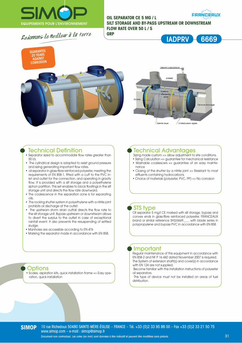
10 rue Richedoux 50480 SAINTE-MÈRE-ÉGLISE – FRANCE – Tél. +33 (0)2 33 95 88 00 – Fax +33 (0)2 33 21 50 75www.simop.com – e-mail : [email protected] non contractuel. Les cotes (en mm) sont données à titre indicatif et peuvent être modifi ées sans préavis.
SIMOP31
6669
OIL SEPARATOR CE 5 MG / LSILT STORAGE AND BY-PASS UPSTREAM OR DOWNSTREAMFLOW RATE OVER 50 L / SGRP
IADPRV
Technical Defi nition• Separator sized to accommodate fl ow rates greater than
50 l/s.• The cylindrical design is adapted to resist ground pressure
and sizing generating important fl ow rates.• oil separator in glass-fi bre reinforced polyester, meeting the
requirements of EN 858-1, fi tted with a cuff to the PVC in-let and outlet for the connection, and operating in gravity fl ow. It is provided with a silt storage and a polyethylene siphon partition. This set enables to block fl oatings in the silt storage unit and directs the fl ow rate downward.
• The coalescence in the separation zone is for separating oils.
• The rocking shutter system in polyethylene with a nitrile joint prohibits oil discharge at the outlet.
• The upstream storm drain outfall directs the fl ow rate to the silt storage unit. Bypass upstream or downstream allows to divert the surplus to the outlet in case of exceptional rainfall event. It also prevents the resuspending of settled sludge.
• Manholes are accessible according to EN 476• Marking the separator made in accordance with EN 858.
Technical Advantages Sizing made custom => allow adjustment to site conditions.• Sizing Calculation => guarantee for mechanical resistance• Washable coaslescers => guarantee of an easy mainte-
nance• Closing of the shutter by a nitrile joint => Resistant to most
effl uents containing hydrocarbons• Choice of materials (polyester, PVC, PP) => No corrosion
Options• Scales, aspiration kits, quick installation frame => Easy ope-
ration, quick installation
STS typeOil separator 5 mg/l CE marked with silt storage, bypass and convex ends in glass-fi bre reinforced polyester, FRANCEAUX brand or similar reference SH3/6669____ with blade series in polypropylene and bypass PVC in accordance with EN 858.
ImportantRegular maintenance of this equipment in accordance with EN 858-2 and NF P 16 442 dated November 2007 is required.The System of extension shaft(s) and cover(s) in accordance with EN 124 are not supplied. Become familiar with the installation instructions of polyester oil separators. This type of device must not be installed on areas of fuel distribution.
GUARANTEE20 YEARSAGAINST
CORROSION

10 rue Richedoux 50480 SAINTE-MÈRE-ÉGLISE – FRANCE – Tél. +33 (0)2 33 95 88 00 – Fax +33 (0)2 33 21 50 75www.simop.com – e-mail : [email protected] non contractuel. Les cotes (en mm) sont données à titre indicatif et peuvent être modifi ées sans préavis.
SIMOP32
SELECTION TABLEOIL LEVEL ALARMS
OILS SLUDGE OVERFLOWGSM SOLAR SOLAR – GSM
REFERENCE
ANH
22/1
4320
shee
t 498
2 pa
ge 4
3
ANH
22/1
5200
shee
t 498
2 pa
ge 4
3
ANH
22/1
4506
shee
t 498
1 pa
ge 4
2
ANH
22/1
4507
shee
t 498
1 pa
ge 4
2
ANB2
2/14
321
shee
t 497
8 pa
ge 4
4
ANL2
2/14
321
shee
t 497
9 pa
ge 4
5
STANDARD
IP65 Box (-20 / +60 ° C)IP68 oil sensor5 linear meter cableIntrinsically safe [EExia] IIC.degree ofpollution 2
BOXABS 185X185 (depth 62mm)
ABS 185X185 (depth 62mm)
PRV 330x430 (200mm depth)
PRV 330x430 (200mm depth)
ABS 185X185 (depth 62mm)
ABS 185X185 (depth 62mm)
ACOUSTICS YES YES NO NO YES YES
APPROVAL ATEX
Baseefa 08 ATEX 0110 (England)
Baseefa 08 ATEX 0110 (England)
Baseefa 08 ATEX 0171X (England)
Baseefa 08 ATEX 0171X (England)
Baseefa 08 ATEX 0110 (England)
Baseefa 08 ATEX 0110 (England)
VISUALA warning mes-sage on housing
A warning mes-sage on housing
A warning mes-sage on housing
A warning mes-sage on housing
A warning mes-sage on housing
A warning mes-sage on housing
SMS (8 issues in reception)
NO YES NO YES NO NO
POWER220-240Vac
50/60 Hz 220-240Vac
50/60 Hz12VDC SOLAR
PANEL12VDC SOLAR
PANEL220-240Vac
50/60 Hz 220-240Vac
50/60 Hz
BUZZER SOUND LEVEL (0.1 m)
>80 dB >80 dB - - >80 dB >80 dB
nb of relays1 (3A-250Vac-
100Vcc)2 (3A-250Vac-
100Vcc)1 (100mA-
12Vcc)1 (100mA-
12Vcc)1 (3A-250Vac-
100Vcc)1 (3A-250Vac-
100Vcc)
FIXING WALL WALL PILLAR PILLAR WALL WALL
OPTIONS reference
BEACON GYRO/ANH YES YES YES (in series) YES YES YES
SOLENOID VALVE ELT-220-50-NF YES YES NO NO YES YES
SOLENOID VALVE ATEX
SOLENOID-WKB2-3/4
YES YES NO NO YES YES
SLUDGE BLANKET SENSOR IP68
SNB/14220 YES YES YES YES YES YES
HIGH LEVEL SENSOR IP68
SNL/14210 YES YES YES YES YES YES

10 rue Richedoux 50480 SAINTE-MÈRE-ÉGLISE – FRANCE – Tél. +33 (0)2 33 95 88 00 – Fax +33 (0)2 33 21 50 75www.simop.com – e-mail : [email protected] non contractuel. Les cotes (en mm) sont données à titre indicatif et peuvent être modifi ées sans préavis.
SIMOP33
4981
OIL LEVEL ALARMPOWERED BY SOLAR PANEL
OperationThe control unit can control up to 6 sensors installed on two different separators (3 sensors per tank). The unit controls the connected sensors every 30 minutes (adjustable frequency). The current state is displayed on the 2X16 LCD screen loca-ted on the front of the unit. Oils are detected by conduc-tion, water acts as a conductor while oils act as isolators. The sensor consists of two stainless steel parts, when one part is immersed in oil, a signal is sent to the control box which triggers the alarm. The control unit detects the alarm condition of the sensor, it comes in two versions :- One reported alarms with a visual noisy signal.- The second transmits the state of the sensors by GSM (SMS on mobile phone). A central alarm signal, a modem, or others external alarm devices can also be connected to the relay.
UseThis alarm system detects the oil level in the separator com-partment just before shutter. The photovoltaic alarm is sui-table for isolated locations where there is no electricity sup-ply available. In addition, the photovoltaic cell produces electricity necessary to the plant by transforming a portion of solar radiation.
Installation Refer to the installation instructions P083 concerning steel oil separators.Installation and use instructions are delivered with the alarm.The maximum length of the sensor cable is 200 m. All connec-tions must be made by a professionnal, assistance may be of-fered as an option. Is is essential that the solar panel is facing south, his line of sight to the sun is clear and it is free of foreign matter (for instance : leaf)
Technical Defi nition- Ambient temperature : -20 ° C to 50 ° C- 6 sensor inputs- Voltage : 12 VDC- Relay outlet : 12 VDC, 100 mA- Box protection : IP65- Intrinsically safe : [EX ia] IIC (-20 ° C <= Ta <= +50 ° C)- ATEX Certifi cation : Base efa08ATEX0171X- Length of sensor cable: 5 m
Oil level alarm SIMOPpowered by a solar panel
Reference Designation
ANH22/14506 Visual and sound oil level alarm IP65 powered by a solar panel
ANH22/14507 Visual and sound level alarm IP65 + GSM powered by a solar panel
SNH/14200 Sensor detecting the oil level
SNB/14220 Sensor detecting the sludge level
SNL/14210 Sensor detecting the liquid level
CR-ANH Extension cable ATEX
MR-ANH Connecting pipe ATEX
MaintenanceThe sensors can be exposed to harsh environments. it is recommended to inspect and clean them regularly.The maintenance of the pieces of the control unit may not be performed by the user. For any repair, please contact us.
Advice and StandardsThe oil level alarm is a compulsory equipment of an oil
separator in accordance with Standard EN858.
ALARM

10 rue Richedoux 50480 SAINTE-MÈRE-ÉGLISE – FRANCE – Tél. +33 (0)2 33 95 88 00 – Fax +33 (0)2 33 21 50 75www.simop.com – e-mail : [email protected] non contractuel. Les cotes (en mm) sont données à titre indicatif et peuvent être modifi ées sans préavis.
SIMOP34
ALARM
SIMOP Alarm
Reference Designation
ANH22/14320 Visual and sound oil level alarm IP65
ANH22/15200 Visual and sound oil level alarm IP65 + GSM
OIL LEVEL ALARM
4982
MaintenanceThe sensors can be exposed to harsh environments. it is recommended to inspect and clean them regularly.The maintenance of the pieces of the control unit may not be performed by the user. For any repair, please contact us.
Advice and NormsThe oil level alarm is a compulsory equipment of an oil sepa-
rator in accordance with Standard EN858.
OperationThe control unit can control up to 3 sensors. The unit controls the connected sensors every 30 minutes (adjustable fre-quency). The current state is displayed on the 2X16 LCD screen located on the front of the unit.Oils are detected by conduction, water acts as a conductor while oils act as isolators. The sensor consists of two stainless steel parts, when one part is immersed in oil, a signal is sent to the control box which triggers the alarm. The control unit detects the alarm condition of the sensor, it comes in two versions :- One reported alarms with a visual noisy signal.- The second transmits the state of the sensors by GSM (SMS on mobile phone). A central alarm signal, a modem, or others external alarm devices can also be connected to the relay.
UseThis alarm system detects the oil level in the separator com-partment just before shutter. The alarm is suitable for new locations where electricity supplyis easily available making installation effi cient and economical.
Installation Refer to the installation instructions P083 concerning steel oil separators ; P084 for polyethylene oil separators.Installation and use instructions are delivered with the alarm.The maximum length of the sensor cable is 200 m. All connec-tions must be made by a professionnal, assistance may be of-fered as an option. Is is essential that the solar panel is facing south, his line of sight to the sun is clear and it is free of foreign matter (for instance : leaf)
Technical Defi nition- Ambient temperature : - 20 ° C to 50 ° C- 3 sensor inputs- Voltage : 230 VAC + / -10%- Relay outlet : 230Vac, 3A- Box protection : IP65- Intrinsically safe : [EX ia] IIC (-20 ° C <= Ta <= +50 ° C)- ATEX : Base efa08ATEX0110X- Length of sensor cable : 5 m
SNB/14220 Sensor detecting the sludge level
SNL/14210 Sensor detecting the liquid level
CR-ANH Extension cable ATEX
MR-ANH Connecting pipe ATEX

10 rue Richedoux 50480 SAINTE-MÈRE-ÉGLISE – FRANCE – Tél. +33 (0)2 33 95 88 00 – Fax +33 (0)2 33 21 50 75www.simop.com – e-mail : [email protected] non contractuel. Les cotes (en mm) sont données à titre indicatif et peuvent être modifi ées sans préavis.
SIMOP35
SLUDGE LEVEL ALARMANB22/14321
4978 ALARM2
Use• Detection of the maximum level of sludge• Acoustic alarm device incorporated• 1 oulet relay inverter• Detection of faulty sensor with 5 m cable• Repeat function and alarm memory• Certifi ed Ex (ATEX)
OperationUltrasonic sensor comprising a transmitter and a receiver. If the wave emitted by the transmitter is blocked by mud and does not reach the receiver, the relay activates the alarm.The alarm relay has incorporated an acoustic device. A central alarm system, a modem, a fl ashing light or external alarm device can be connected to the relay.The sensor associated with the relay make the difference between the liquid and the sludge, and between liquid and air.We detect thus a sludge level or a level loss (leakage). Instal-lation and connections, please contact us or call a licensed electrician.To activate the installation, call a hotline indicated on the front of the box and you will have the activation code.
Advice and StandardsThe sludge detection assembly can be coupled to the oil layer detection sensor (Ref. SNH/14200) and to the high level detection sensor (Ref. SNL/14210). The installation must not exceed 200 meters in a confi guration in a IIC area and whatever the sensors’number. Possibility of wiring a light beacon (Ref. GYRO/ANH).
Warning !The box must be installed outside ATEX zone. The control box should never be drilled to allow the passage of cables.This could compromise the certifi cation and therefore the safety of the equipment. A intrinsically safe junction box should be used when the cable sections must be reduced to the passage in the cable gland.
Technical features of the relay
• Material : ABS• Dimensions : 185 mm x 185 mm, depth: 62 mm• Power supply : 230 VAC ± 10%. frequency : 50-60Hz• Consumption : 6 VA / 4,5 VA (Max/Nominal)• Relay outlet 1 : contact SPCO volt free changeover
(normally closed) 3 A, 250 VAC VAC/100• Intensity breakdown : F100 mA - 250 V• 3 sensor inlets: oil sensor, high level sensor, sludge blanket• Ambient temperature: -25 ° C / + 50 ° C• Confi guration : Programming with an activation code• Enclosure : IP65 (against dust and water jets)• Electrical protection : Class II. Protection internal fuse: FS1 =
63 mA, 315 mA = FS2, FS3 = 50 mA• Sound buzzer : > 80 dB (0.1 m distance)• audible frequency : 4kHz• Degree of pollution : 2• Approval : Baseefa (England)• ATEX Certifi cation : Baseefa08 ATEX 0110
Sensor Specifi cations• 5 meter cable• The sensor can be connected only to the internal power
supply of the box• Supply voltage : 13 Vcc max• Ambient temperature : - 20 ° C/+ 50 ° C• Protection IP68• Certifi cation : Ex ia IIC T3• Control responsible agency : international Baseefa
(England)• ATEX Certifi cation : Baseefa08 ATEX 0110
EN858-1

10 rue Richedoux 50480 SAINTE-MÈRE-ÉGLISE – FRANCE – Tél. +33 (0)2 33 95 88 00 – Fax +33 (0)2 33 21 50 75www.simop.com – e-mail : [email protected] non contractuel. Les cotes (en mm) sont données à titre indicatif et peuvent être modifi ées sans préavis.
SIMOP36
ALARM DETECTING OVERFLOWANL22/14321
4979
OperationThe sensor is equipped with an electronic circuit which trans-mits a high frequency signal thanks to an oscillator. This signal varies when the sensor is placed in water, air or oil.The alarm relay has incorporated an acoustic device. A central alarm system, a modem, a fl ashing light or external alarm device can be connected to the relay.The sensor associated with the relay detects the overfl ow (maximum level) of the separator, and prevents any over-fl ow. Installation and connections, please contact us or call a licensed electrician.
Use• Detection of the separator maximum level preventing any
risk of overfl ow• Acoustic alarm device incorporated• 1 oulet relay inverter• Detection of faulty sensor with 5 m cable• Repeat function and alarm memory• Certifi ed Ex (ATEX)
Advice and StandardsThe high level detection assembly can be coupled with the detection alarm of oil layers ANH/14200 and with the mud detection sensor SNB/14220.The installation must not exceed 200 meters in a confi guration in a IIC area and whatever the sensors’number. Possibility of wiring a light beacon (Ref. GYRO/ANH).
Warning !The box must be installed outside ATEX zone. The control box should never be drilled to allow the passage of cables.This could compromise the certifi cation and therefore the safety of the equipment. A intrinsically safe junction box should be used when the cable sections must be reduced to the passage in the cable gland. The box is IP65 and the sensor IP68.
Sensor Specifi cations• 5 meter cable• The sensor can be connected only to the internal power
supply of the box• Supply voltage : 13 Vcc max• Ambient temperature : - 20 ° C/+ 50 ° C• Protection IP68• Certifi cation : Ex ia IIC T3• Control responsible agency : international Baseefa
(England)• ATEX Certifi cation : Baseefa08 ATEX 0110
Technical features of the relay
• Material : ABS• Dimensions : 185 mm x 185 mm, depth: 62 mm• Power supply : 230 VAC ± 10%. frequency : 50-60Hz• Consumption : 6 VA / 4,5 VA (Max/Nominal)• Relay outlet 1 : contact SPCO volt free changeover
(normally closed) 3 A, 250 VAC VAC/100• Intensity breakdown : F100 mA - 250 V• 3 sensor inlets: oil sensor, high level sensor, sludge blanket• Ambient temperature: -25 ° C / + 50 ° C• Confi guration : Programming with an activation code• Enclosure : IP65 (against dust and water jets)• Electrical protection : Class II. Protection internal fuse: FS1 =
63 mA, 315 mA = FS2, FS3 = 50 mA• Sound buzzer : > 80 dB (0.1 m distance)• audible frequency : 4kHz• Degree of pollution : 2• Intrisincally Safe : (Eexia) IIC• Approval : Baseefa (England)• ATEX Certifi cation : Baseefa08 ATEX 0110
ALARM3
EN858-1

10 rue Richedoux 50480 SAINTE-MÈRE-ÉGLISE – FRANCE – Tél. +33 (0)2 33 95 88 00 – Fax +33 (0)2 33 21 50 75www.simop.com – e-mail : [email protected] non contractuel. Les cotes (en mm) sont données à titre indicatif et peuvent être modifi ées sans préavis.
SIMOP37
BOX OR JUNCTION SLEEVECABLE FOR HYDRO ATEX ALARM
4977
UseIt allows to extend the connection when the oil sensors, sludge sensors, or high level sensors are located more than 5 m from the electrical box. They also guarantee the pro-per functioning of the system and compliance with the ATEX standard of the installation with its cable.
Technical features of the junction box
Reference: BOITIER-JONCTIONPossibility of connecting 2 sensors (2 inlets, 1 outlet) :• Oil detection sensor and high level sensor• Sludge detection sensor and high level sensor• IP67 protection• Box length : 100 mm• Box depth : 48mm• Case height : 66 mm• Overall height (with cable gland) : 92 mm• Weight: 0.27 kg• The box is ATEX approved
Technical features of the junction sleeveReference : MR-ANHConnecting a sensor (1 inlet, 1 outlet) :• Oil detection sensor• High level sensor• Sludge sensor• IP67 protection• Sleeve diameter : ø 28 mm• Sleeve length : 108 mm• Weight: 0.06 kg• it has the advantage of being housed in a sheath• The sleeve is ATEX approved
Technical features of the cable
Reference : CR-ANHWhen you need to extend your connection, the whole loop must not exceed a resistivity of 20 Ω/m (for the oil sensor) and 10 Ω/m for the high level sensor and sludge sensor.The installation must not exceed 250 meters for connection of a oil sensor and 100 meters for connection of two sensors (oil / high level or sludge high level).Cable Ø : 5 mm (cable sold by the linear meter) CAUTION : The cable(s) of the sensors should be inserted into sheaths independent of power cables (disturbances may af-fect the measured signal).
BMJ
EN858-1

10 rue Richedoux 50480 SAINTE-MÈRE-ÉGLISE – FRANCE – Tél. +33 (0)2 33 95 88 00 – Fax +33 (0)2 33 21 50 75www.simop.com – e-mail : [email protected] non contractuel. Les cotes (en mm) sont données à titre indicatif et peuvent être modifi ées sans préavis.
SIMOP38
Defi nitionExtension shafts for oil separators SIMOP are designed and coated blasted steel which ensures their strength and dura-tion. They are designed to provide freeze protection and let ac-cess to the frame. Access to the separator is indeed indispen-sable for its maintenance and good operation.They are designed for separators with CE marking and with EN 1825, EN858 and EN124 standards.
STEP 2
STEP 1 STEP 3
End of the separator reference without protection
Choose the appropriate reference to the moving load
RP1L RP1T RP2L RP2T Frame 125 KN-577 x 673 Frame 250 KN-577 x 673
Possible adjustment of 150 mm Qty Qty Qty Qty Reference Reference
Longitudinal extension shaft H200/350 1 2 TF125P/H2035L TF250P/H2035L
Transverse extension shaft H200/350 1 2 TF125P/H2035T TF250P/H2035T
Longitudinal extension shaft H350/500 1 2 TF125P/H3550L TF250P/H3550L
Transverse extension shaft H350/500 1 2 TF125P/H3550T TF250P/H3550T
Longitudinal extension shaft H500/650 1 2 TF125P/H5065L TF250P/H5065L
Transverse extension shaft H500/650 1 2 TF125P/H5065T TF250P/H5065T
Longitudinal extension shaft H650/800 1 2 TF125P/H6580L TF250P/H6580L
Transverse extension shaft H650/800 1 2 TF125P/H6580T TF250P/H6580T
Longitudinal extension shaft H800/950 1 2 TF125P/H8095L TF250P/H8095L
Transverse extension shaft H800/950 1 2 TF125P/H8095T TF250P/H8095T
End of the reference separatorwithout protection Choose the appropriate reference to the moving load
RG1L RG2T RG3T RG4T RG5T Frame 125 KN-577 x 922 Frame 250 KN-577 x 922
Possible adjustment of 150 mm Qty Qty Qty Qty Qty Reference Reference
Longitudinal extension shaft H200/350 1 TF125G/H2035L TF250G/H2035L
Transverse extension shaft H200/350 2 3 4 5 TF125G/H2035T TF250G/H2035T
Longitudinal extension shaft H350/500 1 TF125G/H3550L TF250G/H3550L
Transverse extension shaft H350/500 2 3 4 5 TF125G/H3550T TF250G/H3550T
Longitudinal extension shaft H500/650 1 TF125G/H5065L TF250G/H5065L
Transverse extension shaft H500/650 2 3 4 5 TF125G/H5065T TF250G/H5065T
Longitudinal extension shaft H650/800 1 TF125G/H6580L TF250G/H6580L
Transverse extension shaft H650/800 2 3 4 5 TF125G/H6580T TF250G/H6580T
Longitudinal extension shaft H800/950 1 TF125G/H8095L TF250G/H8095L
Transverse extension shaft H800/950 2 3 4 5 TF125G/H8095T TF250G/H8095T
Reference
Blanking plate 577 x 673 TR4/P
Blanking plate 577 x 922 TR4/G
INSTRUCTIONSSTEP 1 : Identify the end of the separator reference and keep in mind the number of closures indicated in the corresponding column.STEP 2 : Choose the height of the extension shaft (note : this is not the inlet level but the height from the top of the separator).STEP 3 : Determine the reference of the protection according to the moving load.
IMPORTANT : Quantities in green can be reduced by replacing some sets extension shaft/frame with steel blanking plates TR4/P or TR4/G (fac-tory made)
ACCESSORIESFOR OIL SEPARATORSTEEL RANGE
4984RH

10 rue Richedoux 50480 SAINTE-MÈRE-ÉGLISE – FRANCE – Tél. +33 (0)2 33 95 88 00 – Fax +33 (0)2 33 21 50 75www.simop.com – e-mail : [email protected] non contractuel. Les cotes (en mm) sont données à titre indicatif et peuvent être modifi ées sans préavis.
SIMOP39
6069
ADJUSTABLE EXTENSION SHAFTSFOR OIL SEPARATORPE RANGE
Defi nitionExtension shafts in high density polyethylene.This material is stable and durable.Extension shafts adjustable from 300 to 450 mm and designed to provide freeze protection and let access to the frame. Ac-cess to the separator is indeed indispensable for its mainte-nance and good operation.
Reference A B D
RH6069 300 à 450 900 x 820 600 x 690
UseExtension shafts suitable for polyethylene separators with rec-tangular frame.
InstallationPut the extension shaft on the U-frame of the separators and set the desired height by drilling and screwing it.
RHPEH
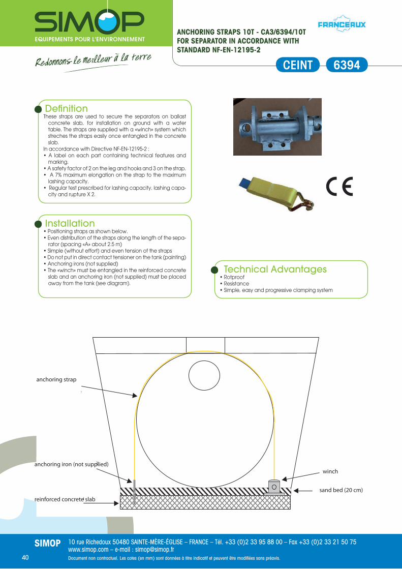
10 rue Richedoux 50480 SAINTE-MÈRE-ÉGLISE – FRANCE – Tél. +33 (0)2 33 95 88 00 – Fax +33 (0)2 33 21 50 75www.simop.com – e-mail : [email protected] non contractuel. Les cotes (en mm) sont données à titre indicatif et peuvent être modifi ées sans préavis.
SIMOP40
6394
ANCHORING STRAPS 10T - CA3/6394/10TFOR SEPARATOR IN ACCORDANCE WITH STANDARD NF-EN-12195-2
Defi nitionThese straps are used to secure the separators on ballast
concrete slab, for installation on ground with a water table. The straps are supplied with a «winch» system which streches the straps easily once entangled in the concrete slab.
In accordance with Directive NF-EN-12195-2 : • A label on each part containing technical features and
marking.• A safety factor of 2 on the leg and hooks and 3 on the strap.• A 7% maximum elongation on the strap to the maximum
lashing capacity.• Regular test prescribed for lashing capacity. lashing capa-
city and rupture X 2.
Technical Advantages• Rotproof• Resistance• Simple, easy and progressive clamping system
Installation• Positioning straps as shown below.• Even distribution of the straps along the length of the sepa-
rator (spacing «A» about 2.5 m)• Simple (without effort) and even tension of the straps• Do not put in direct contact tensioner on the tank (painting)• Anchoring irons (not supplied)• The «winch» must be entangled in the reinforced concrete
slab and an anchoring iron (not supplied) must be placed away from the tank (see diagram).
CEINT
Dalle béton
armé
Ceinture
d'ancrage
Fer d'ancrage (hors
fournitures) Winch
Lit de sable (20 cm)
anchoring strap
anchoring iron (not supplied)
reinforced concrete slab
winch
sand bed (20 cm)
EN858-1
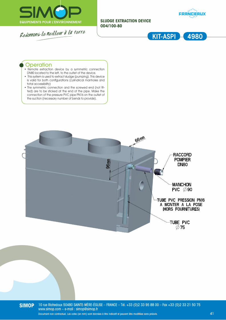
10 rue Richedoux 50480 SAINTE-MÈRE-ÉGLISE – FRANCE – Tél. +33 (0)2 33 95 88 00 – Fax +33 (0)2 33 21 50 75www.simop.com – e-mail : [email protected] non contractuel. Les cotes (en mm) sont données à titre indicatif et peuvent être modifi ées sans préavis.
SIMOP41
SLUDGE EXTRACTION DEVICEOD4/100-80
4980KIT-ASPI
Operation• Remote extraction device by a symmetric connection
DN80 located to the left, to the outlet of the device.• This system is used to extract sludge (pumping). This device
is valid for both confi gurations (cylindrical manholes and total accessibility)
• The symmetric connection and the screwed end (not fi t-ted) are to be sticked at the end of the pipe. Make the connection of the pressure PVC pipe PN16 on the outlet of the suction (necessary number of bends to provide).

10 rue Richedoux 50480 SAINTE-MÈRE-ÉGLISE – FRANCE – Tél. +33 (0)2 33 95 88 00 – Fax +33 (0)2 33 21 50 75www.simop.com – e-mail : [email protected] non contractuel. Les cotes (en mm) sont données à titre indicatif et peuvent être modifi ées sans préavis.
SIMOP42
OIL BELT TRANSFEROD4/2102
4988CAPT
Installation dimensions of the chute :TYPE OF DEVICE Y
(mm)X
(mm)Setting of the chute H (mm)
SH4808/01/00 568 349 540
SH4804/01/00 – SH4824/01/00 357 439 300
SH4814/03/00 – SH4808/03/00 613 346 630
SH4804/03/00 – SH4810/03/00 – SH4824/03/00 497 804 440
SH4814/06/00 – SH4808/06/00 628 900 750
SH4810/06/00 – SH4804/06/00 – SH4824/06/00 500 349 540
SH4808/08/00 776 1000 750
SH4814/08/00 745 1000 750
SH4810/08/00 – SH4804/08/00 – SH4824/08/00 585 349 630
SH4808/10/00 – SH4814/10/00 861 1000 880
SH4808/15/00 944 1000 880
SH4808/15/00 694 1000 880
SH4810/15/00 – SH4804/15/00 – SH4824/15/00 694 755 650
SH4814/20/00 – SH4808/20/00 1025 1000 960
SH4810/20/00 – SH4804/20/00 – SH4824/20/00 752 900 750
SH4810/25/00 – SH4804/25/00 – SH4824/25/00 832 1000 880
SH4810/30/00 – SH4824/30/00 – SH4804/30/00 709 1000 750
SH4810/35/00 – SH4804/35/00 – SH4824/35/00 764 1000 880
SH4810/40/00 – SH4824/40/00 – SH4804/40/00 876 1000 880
SH4810/50/00 – SH4804/50/00 – SH4824/50/00 1005 1000 960
SH4730/01 500 439 380
SH4730/03 - SH4730/06 500 500 470
UseThis system allows to recover hydrocarbons through a chute and evacuate them to a holding tank. It can also delay the interven-tion of the pumper when a storage tank is placed near the sepa-rator, and ensure safety in the event of accidental spill.
SettingA preset is done in factory. The edge of the chute must be
between 10 and 20 mm below the water outlet level. The adjustment is made by screwing in/screwing out the screw on the side of the chute. We recommend you to calibrate the chute on the top rail, to have a greater range of adjust-ment in case the calibration is changed.
CAUTION : To avoid obstruction of the connection system pipe, the slope must be suffi ciently large.
Operation The gravity discharge of hydrocarbons is carried by the
chute inside the separator and is released to the outside by a spur ND20 (diameter ø 20mm) on the left lateral side* (default) of the separator. The system operates through the handle of the valve located at the manholes (cylindrical or rectangular) of the separator. When the separator is satu-rated with oil and that the fl oat is embedded in the layer, open the valve. Closing the valve as soon as all of the oil layer was removed.
* If the installation should be done right, please let us know.
X (mm)
chute
Y (m
m)
pitti
ng p
ositi
on
Position of the system on the inlet side of the separator. Pitting ø 26.9 mm in the axisof the manhole at the level of the coales-cence
Oil belt transfer
Length of wire 5 m (default)electrical box
Oil separator
Oil detection sensor
Pipe (not supplied)
Storage tank
Solenoid valveReference: ELTV-220-50-NF

10 rue Richedoux 50480 SAINTE-MÈRE-ÉGLISE – FRANCE – Tél. +33 (0)2 33 95 88 00 – Fax +33 (0)2 33 21 50 75www.simop.com – e-mail : [email protected] non contractuel. Les cotes (en mm) sont données à titre indicatif et peuvent être modifi ées sans préavis.
SIMOP43
EXTERNAL CATHODIC PROTECTIONOD/2145
4985ANODE
Technical AdvantagesThe cathodic protections are used to slow corrosion of the metal particularly due to the existence of stray currents in the ground. This slowing down is achieved by the provision of a more electronegative potential than steel through an anode called «sacrifi cial» composed, for most of them, of magne-sium or zinc in specifi c applications (saline).
Operation• An «sacrifi cial» anode in magnesium is consumed progressi-
vely on contact with stray currents existing in the ground be-cause its potential is more electronegative than steel.
• Electronegative potential of steel : - 0.44 volt• Electronegative potential of magnesium : - 1.55 volt
Constitution and featuresIt is made of magnesium and backfi ll, all contained in a cot-ton bag.• Length : 400 mm• Diameter : 200 mm• Weight of AZ63 magnesium anode : 5 kg• Total weight : 15 kg• Backfi ll corrosion control : 10 kg• Cable cross-section : 6 mm²• Cable length : 10 meters• Electronegative potential of magnesium : -1.55 volt• Strength of current available : 10 to 20 Ma• Utilization factor : 50%• Protectable surface by anode: 25 m²*• Life cycle : 10 years*
There is an option, an interconnection box to verify the effi -ciency of the anodes and control the wear rate. This box can be set in the concrete manhole (see diagram).
Assembly (in accordance with NF P 16 442, Novembre 2007).It is important to ensure that the tanks are well insulated of all the other metal structure and be sure the terracing and embankment works of the tanks are completed.Connect the cathodic protections at the level of the reinfor-cements situated on the parallelipedic and cylindrical tanks (hole). The electric cable of the anode will be placed in a sheath before installation. The anodes must be wet.Interconnection box option : it controls the electrical measure-ments of the polarization of the cathodic protection. It is an aluminium box containing a copper bar*
*Values only valid in the presence of a coating which are resistant and where the isolation is greater than 104 m² and of an electrlyte with a neutral Ph and resistivity less than 50 m.
Wiring diagram fo a cylindrical device according to NF P 16-442 (November 2007) :

10 rue Richedoux 50480 SAINTE-MÈRE-ÉGLISE – FRANCE – Tél. +33 (0)2 33 95 88 00 – Fax +33 (0)2 33 21 50 75www.simop.com – e-mail : [email protected] non contractuel. Les cotes (en mm) sont données à titre indicatif et peuvent être modifi ées sans préavis.
SIMOP44
GRAVEL FILTER DRAINWITH FIREWALLAVCF01
4992AVCF
Disposal of the drainson helipadThe drain gravel fi lter is a part of the equipment of a helipad on the terrace.This is a safety device preventing the fi re spread to other parts of buildings when there is a fuel fl ow or when there is a crash landing of a helicopter. Filter drains shall be fi lled with gravel under the grate and wa-ter in the silt storage siphon.
Features• Water volume in the siphon : 46 dm3• Total weight : 170 kg• Grating and frame weight : 77 kg• Gross weight : 304 kg• Gravel density : 1450 kg/dm3
See diagram below for other specifi cations*stainless steel on request.
Firewall drainsGravel fi lters are constituted by a cylindrical tank made of galvanized steel with a 65 cm inside diameter containing gravel size 10/20 mm to a thickness of about 20 cm. These gravel have the ability to absorb a fl ow rate of about 5 to 10 l/sec (depending on the gravel type). The drain is formed in the upper portion of a gravel fi lter co-vered by a grating and a cast iron installation frame (700x700-250kN) and a silt storage siphon as a fi rewall at the bottom.Connections to the network are made using fl at fl anges.Oil detection device, brand FRANCEAUX ANH22/14320 or si-milar, ATEX certifi ed. IP65 box.
1/2

10 rue Richedoux 50480 SAINTE-MÈRE-ÉGLISE – FRANCE – Tél. +33 (0)2 33 95 88 00 – Fax +33 (0)2 33 21 50 75www.simop.com – e-mail : [email protected] non contractuel. Les cotes (en mm) sont données à titre indicatif et peuvent être modifi ées sans préavis.
SIMOP45
GRAVEL FILTER DRAINWITH FIREWALLAVCF01
4992AVCF
ImplantationDrains are installed in the landing zone. They are connected to the rain water network via a device separating hydrocar-bons. This device may be installed either directly under the terrace, at the foot of the building or distributed between these two locations.
The device must include the following parts :• Drain with a gravel fi lter acting as a fi rewall• Silt storage siphon • Silt storage high capacity (silt storage foot drop regulating the fl ow rate)• Oil separator with self shutter and evacuation device for hydrocarbons in excess• Tank collecting a massive fuel fl ow rate of an equivalent capacity to the volume of the helicopers’ tanks (see classi-fi cation below).
Remarks :It is possible to simplify the installation by removing the tank when the retention capacity of the separator is greater than the capacity of the helicopters’ tanks.Maximum capacity of the helicopters’ tanks :group 3 = 2000 litersgroup 4 = 1000 liters
Protect the installation against frost (ventilated place in the under terrace confi guration ; frost protection implementation in the buried confi guration). Provide adequate ventilation to disperse the oil vapors and consider that they are a danger zone.
HELIPAD CATEGORY 3
HELIPAD CATEGORY 4
2/2

10 rue Richedoux 50480 SAINTE-MÈRE-ÉGLISE – FRANCE – Tél. +33 (0)2 33 95 88 00 – Fax +33 (0)2 33 21 50 75www.simop.com – e-mail : [email protected] non contractuel. Les cotes (en mm) sont données à titre indicatif et peuvent être modifi ées sans préavis.
SIMOP46
INSTALLATION INSTRUCTIONSOF A PARALLELIPEDIC DEVICEWITH MANHOLE COVERS
Refer to standard NF P16-442 for light liquid separators and silt storages and to standard NF EN 1825-2 for grease separators.
For handling of the separator, it is essential to lift up the device using the 4 lugs. Check the condition of the lining before lowering the separator into the hole.1) Carry out the earthwork.2) Overlap the bottom of the excavation with some thick compacted sand (10 cm minimum) which will be laid perfectly level and put the device in place connecting the pipes and the ventilation system.3) Installation of the oil level alarm in the oil or grease separator :REMINDER: according to the standard NF EN 858-1 CE, the oil level alarm is mandatory except if a special derogation has been obtained from local authorities.Before fi lling with water, install a sheath up to the packing box and install the probe as indicated in notice P083 (oil separators) and notice P086 (grease separators).*Be careful : the minimum diameter of the sheath is 80 mm.4) Fill in symmetrically, in successive layers and with sand to the upper level of the separator. It is necessary to proceed with water fi lling of the separator in order to balance pressures before the banking up operations are started.5) Lay 10 cm of sand on top of the device. Pour a reinforced concrete slab which must rest on unturned ground and be capable of withstanding the strains imposed on the manhole cover. If cast iron covers are necessary, they must be put into place before the concrete slab dries out so that a perfect water seal is achieved.
* For oil separators and as per diagram 1 of notice P083, the sheath passes via the concrete covers and can be put on after its immersion in water.
* Anchorage on hydromorphic ground with stowing belts on a reinforced concrete slab(MAXI UPPER LEVEL OF THE GROUNDWATER = WATER ENTRANCE UNIT OF THE DEVICE) In case of sheet groundwater or ground liable to fl ooding, all necessary precautions must be taken such as installing a correctly dimen-sioned reinforced concrete slab, with some retainer rings for the anchoring straps. It should be protected on the lower side by a pad and covered by a layer of gravel and geotextile on the upper side.
P039

10 rue Richedoux 50480 SAINTE-MÈRE-ÉGLISE – FRANCE – Tél. +33 (0)2 33 95 88 00 – Fax +33 (0)2 33 21 50 75www.simop.com – e-mail : [email protected] non contractuel. Les cotes (en mm) sont données à titre indicatif et peuvent être modifi ées sans préavis.
SIMOP47
INSTALLATION INSTRUCTIONSOF A PARALLELIPEDIC DEVICEWITH ADJUSTABLE STEEL EXTENSION SHAFTS
P040
In the absence of Special Technical Specifi cations, refer to the Stan-dard NF P16-442
For handling of the separator, it is essential to lift up the device using the four lugs. Check the condition of the lining before lowering the separator in the hole.
1) Carry out the earthwork.
2) Overlap the bottom of the excavation with some thick compacted sand (10 cm minimum) which will be laid perfectly level and put the device in place connecting the pipes and the ventilation system.
3) Installation of the oil level alarm in the oil or grease separator :
REMINDER: according to standard NF EN 858-1 CE, the oil level alarm is compulsory except if a special derogation has been obtained from local authorities.
Before fi lling with water, install a sheath up to the packing box and install the sensor as indicated in notice P083 (oil separators) and notice P086 (grease separators).
Be careful : the minimum diameter of the sheath is 80 mm.
4) Fill in symmetrically, in successive layers and with sand up to the upper level of the separator. It is necessary to proceed with water fi lling of the separator in order to balance pressures before the banking up operations are started.
5) Pour a reinforced concrete slab which must rest unturned ground and be capable of withstanding the strains imposed on the manhole covers. After opening the manhole covers, apply (from the inside of the extension shaft), a joint putty-glue polyurethane of type PU 40 in the pump around the steel extension shafts in order to guarantee the sealing between the rectangular manhole cover and the extension shaft.
* Anchorage on hydromorphic ground with strowing belts on a reinforced concrete slab(MAXI UPPER LEVEL OF THE GROUNDWATER = WATER ENTRANCE LINE OF THE DEVICE)
In case of sheet groundwater (groundwater, waterlogging, clay soils,...), all necessary precautions must be taken such as installing a correctly dimensioned reinforced concrete slab, with some retainer rings for anchoring straps. Fitting of a piezometer with a minimum diameter of 315 mm is recommended. It should be portected on the lower side by a pad and covered by a layer of gravel and geotextile on the upper side.

10 rue Richedoux 50480 SAINTE-MÈRE-ÉGLISE – FRANCE – Tél. +33 (0)2 33 95 88 00 – Fax +33 (0)2 33 21 50 75www.simop.com – e-mail : [email protected] non contractuel. Les cotes (en mm) sont données à titre indicatif et peuvent être modifi ées sans préavis.
SIMOP48
INSTALLATION INSTRUCTIONSPRE-TREATMENT DEVICESPOLYETHYLENE RANGEFOR OIL SEPARATORS
P041
Stabilized ground - dry ground - ground with no water tableThe device must be buried as close as possible to the place to be treated and outside a building.The cover must reach the natural ground level.
1) Carry out the earthwork and overlap the bottom of the excavation with some thick compacted sand (10 cm minimum) which will be led perfectly level.2) Put the device in place connecting the levels of the pipes.3) Backfi ll with sand and fi ll the device with water.Before fi lling with water, install a sheath up to the packing box and install the sensor as indicated in notice P083 (oil separators) and notice P086 (grease separators).Be careful : the minimum diameter of the sheath is 80 mm.4) Vent pipes must be connected with a recommended diameter of 100 mm and will be capped with a device to prevent the passage of small animals.5) Finish backfi lling up to the cover with sand or topsoil.A slab protection resting on undisturbed ground is necessary in the following cases :- If the inlet level from the ground level is above 50 cm.- In vehicles will drive over the area less than 3 meters away.- In case of cast iron covers.
Note: Put in place extension shafts to let access to the device.
INSTALLATION WITH POLYETHYLENE RECTANGULAR FRAME
(TOTAL ACCESSIBILITY)INSTALLATION WITH POLYETHYLENE MANHOLE COVER
(CAST IRON COVER)

10 rue Richedoux 50480 SAINTE-MÈRE-ÉGLISE – FRANCE – Tél. +33 (0)2 33 95 88 00 – Fax +33 (0)2 33 21 50 75www.simop.com – e-mail : [email protected] non contractuel. Les cotes (en mm) sont données à titre indicatif et peuvent être modifi ées sans préavis.
SIMOP49
TerracingBeware : the altimetric positioning of the tank height must be calculated in such a way that the level of the ground water is not above that of the water outlet level. Dig a separate hole for each tank and if necessary, push down the ground water until after backfi lling work for the device has been carried out. The walls must allow a space of about 70 cm around the tank. The bottom of the sloping which creates a barricade of earth must be at least 4 m around the tank.
HandlingThe tanks must be handled using chain slings to hang on the hoist rings on top of the ring-like and with the hoist (not lift with forks) adapted to the volume of the tank. Chain slings must be provided by the installation company. Expect the accessibility of transport suitable for location (tractor-trailers).
Making a slab protection made of heavily reinforced concrete1) If there is backfi ll in excess of 60 cm above the tank’s upper cone.2) In the presence of groundwater3) If there is occasional overload due to vehicles driving less than 4 m away from the edge of the hole.4) If extension shafts in concrete are to be used.5) If there are overloads due to extreme climatic conditions.
This slab must rest on stable ground which must be non-turned. Beware : Before completion of the concrete slab, the tank must be completely fi lled.
Anchoring strapIt is important to use straps CA3/FX15 when they will be fi xated around the tank and on the irons, they should not be unduly strained to prevent ovalization of the tank.
Special CasesIn the case of implantation in unstable ground and/or silt ground, it is necessary to make the lateral embankment using stabilized sand 200 kg/m3.
P060
INSTALLATION INSTRUCTIONSOIL SEPARATORSPOLYETHYLENE TANK TO BE BURIEDTECHNICAL SHEETS 6647 AND 6648
INSTALLATION ON A NON-HYDROMORPHOUS, NON-CLAY SOILS, SILT GROUND ORGROUND WITH NO WATER TABLE
INSTALLATION ON A HYDROMORPHOUS, NON-CLAYSOILS, SILT GROUNDMAXIMUM HEIGHT GROUNDWATER= WATER OUTLET LEVEL
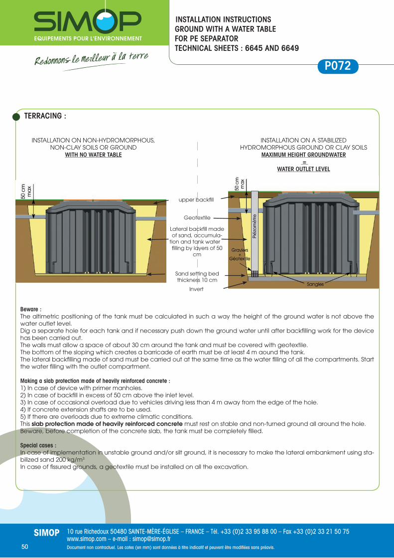
10 rue Richedoux 50480 SAINTE-MÈRE-ÉGLISE – FRANCE – Tél. +33 (0)2 33 95 88 00 – Fax +33 (0)2 33 21 50 75www.simop.com – e-mail : [email protected] non contractuel. Les cotes (en mm) sont données à titre indicatif et peuvent être modifi ées sans préavis.
SIMOP50
P0722014/06/27
INSTALLATION INSTRUCTIONSGROUND WITH A WATER TABLEFOR PE SEPARATOR TECHNICAL SHEETS : 6645 AND 6649
Beware :The altimetric positioning of the tank must be calculated in such a way the height of the ground water is not above the water outlet level.Dig a separate hole for each tank and if necessary push down the ground water until after backfi lling work for the device has been carried out.The walls must allow a space of about 30 cm around the tank and must be covered with geotextile.The bottom of the sloping which creates a barricade of earth must be at least 4 m aound the tank.The lateral backfi lling made of sand must be carried out at the same time as the water fi lling of all the compartments. Start the water fi lling with the outlet compartment.
Making a slab protection made of heavily reinforced concrete : 1) In case of device with primer manholes.2) In case of backfi ll in excess of 50 cm above the inlet level.3) In case of occasional overload due to vehicles driving less than 4 m away from the edge of the hole.4) If concrete extension shafts are to be used.5) If there are overloads due to extreme climatic conditions. This slab protection made of heavily reinforced concrete must rest on stable and non-turned ground all around the hole.Beware, before completion of the concrete slab, the tank must be completely fi lled.
Special cases : In case of implementation in unstable ground and/or silt ground, it is necessary to make the lateral embankment using sta-bilized sand 200 kg/m3
In case of fi ssured grounds, a geotextile must be installed on all the excavation.
TERRACING :
Invert
Geotextile
Sand setting bed thickness 10 cm
Lateral backfi ll made of sand, accumula-
tion and tank water fi lling by layers of 50
cm
upper backfi ll
INSTALLATION ON A STABILIZED HYDROMORPHOUS GROUND OR CLAY SOILS
MAXIMUM HEIGHT GROUNDWATER =
WATER OUTLET LEVEL
INSTALLATION ON NON-HYDROMORPHOUS, NON-CLAY SOILS OR GROUND
WITH NO WATER TABLE
P072
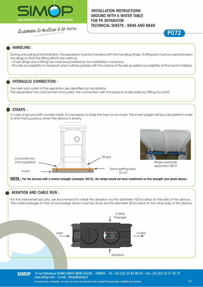
10 rue Richedoux 50480 SAINTE-MÈRE-ÉGLISE – FRANCE – Tél. +33 (0)2 33 95 88 00 – Fax +33 (0)2 33 21 50 75www.simop.com – e-mail : [email protected] non contractuel. Les cotes (en mm) sont données à titre indicatif et peuvent être modifi ées sans préavis.
SIMOP51
During unloading and installation, the separator must be handled with the handling straps. A lifting bar must be used between the slings so that the lifting efforts are vertical.- Chain slings and a lifting bar must be provided by the installation company.- Provide accessibility to transport which will be suitable with the nature of the site (possible accessibility of the tractor-trailers).
HANDLING :
The inlet and outlet of the separator are identifi ed by inscriptions.The separateur has conical inlet and outlet, the connection with the pipes is made easily by fi tting (no joint).
HYDRAULIC CONNECTION :
In case of ground with a water table, it is necessary to strap the tank on an invert. The invert weight will be calculated in order to limit the buoyancy when the device is empty.
NOTA : For the devices with a central strength (example: NS15), the straps would not have constraints on this strength (see photo above).
STRAPS :
For the interveners security, we recommend to install the aeration via the diameter 100 located on the side of the device.The cable passage for the oil and sludge sensor must be done via the diameter 50 located on the other side of the device.
AERATION AND CABLE RUN :
INSTALLATION INSTRUCTIONSGROUND WITH A WATER TABLEFOR PE SEPARATOR TECHNICAL SHEETS : 6645 AND 6649
P0722014/06/27
Inlet Outlet
Aeration
Cable Passage
Concrete iron (not supplied)
Straps
Sand setting bed 10 cmInvert
Straps exampleseparator NS15
P0722014/06/27 P072

10 rue Richedoux 50480 SAINTE-MÈRE-ÉGLISE – FRANCE – Tél. +33 (0)2 33 95 88 00 – Fax +33 (0)2 33 21 50 75www.simop.com – e-mail : [email protected] non contractuel. Les cotes (en mm) sont données à titre indicatif et peuvent être modifi ées sans préavis.
SIMOP52
Works to be done
• If the separator is equipped with manhole, put a mark on the sensor cable as described below and pass the cable through the sheath, put in place by the installation company.
• Attach the cable with the clip to the guiding tube of the shutter so that the mark is positioned at the water level in the sepa-rator (1).
• Electrical connections -------> see instructions supplied with the alarm.
Device Reference
NS Height H
4802480348204821
1.5 244
3 314
6 271
8 366
10 351
15 218
25 249
30 189
35 235
40 331
50 298
Device Reference
NS Height H
48044805481048114824482548304831
1.5 434
3 324
6 371
8 416
10 326
15 253
20 247
25 249
30 269
35 335
40 331
50 348
Device Reference
NS Height H
48084809481448154828482948344835
1.5 470
3 355
6 307
8 267
10 264
15 244
20 204
4816
3 350
6 396
10 371
15 443
Device Reference
NS Height H
4730473147324733
1.5 200
3 210
6 250
INSTALLATION INSTRUCTIONSALARMS ANH22/14320 AND ANH22/15200FOR OIL SEPARATORSTEEL
P083APHA
The Serfl ex collar is used as a mark at the static water level. It will be positioned at this level. To be positioned again at this le-vel during the cleaning of the sensor.
H
Ser ex collar

10 rue Richedoux 50480 SAINTE-MÈRE-ÉGLISE – FRANCE – Tél. +33 (0)2 33 95 88 00 – Fax +33 (0)2 33 21 50 75www.simop.com – e-mail : [email protected] non contractuel. Les cotes (en mm) sont données à titre indicatif et peuvent être modifi ées sans préavis.
SIMOP53
Ser ex collar
Work to be done
• Install the sensor into the separator.• Use the collar installed on the sensor cable to put a mark on the H spot height (you will fi nd this spot height in the table below
according the reference of the oil separator).
• Attach the cable with the clip to the guiding tube of the shutter so that the mark is positioned at the water level in the sepa-rator.
• Electrical connections -------> see instructions supplied with the alarm.
The Serfl ex collar is used as a mark at the static water level. It will be positioned at this level. To be positioned again at this level during the cleaning of the sensor.
Device reference
NS Height H
66436646
1.5 310
3 310
6 310
8 350
10 350
15 310
66446652 6654
3 260
6 260
8 310
10 310
15 310
Device Reference
NS Height H
66506651
3 240
6 260
8 260
10 260
15 260
66486647
20 310
25 310
30 310
INSTALLATION INSTRUCTIONSALARMS ANH22/14320 AND ANH22/15200FOR OIL SEPARATORSPOLYETHYLENE
P084APHP
H
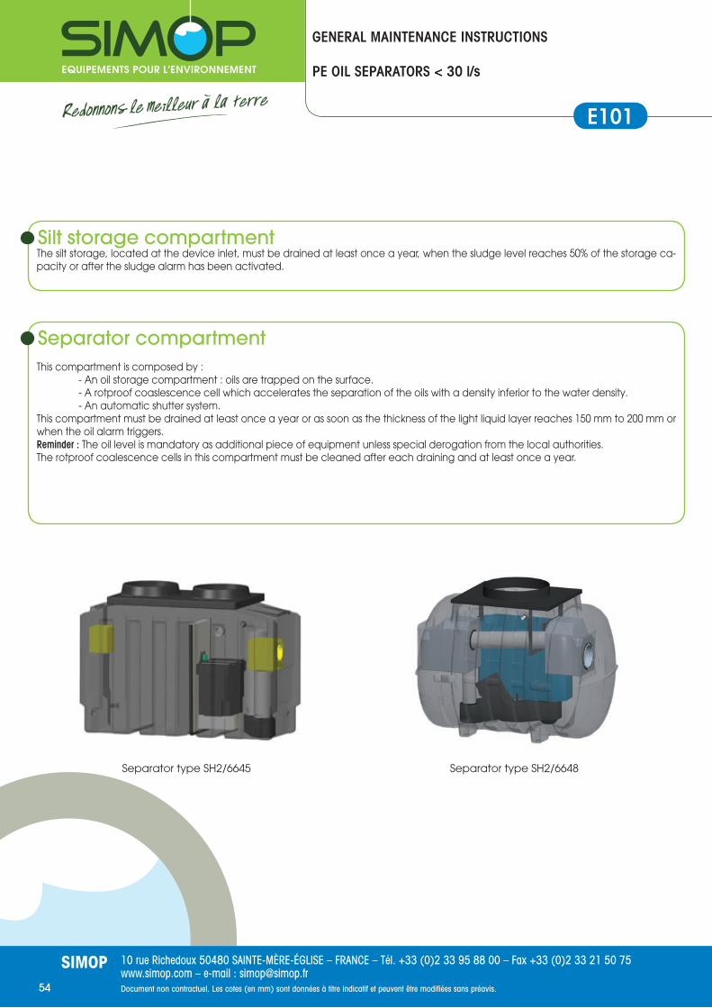
10 rue Richedoux 50480 SAINTE-MÈRE-ÉGLISE – FRANCE – Tél. +33 (0)2 33 95 88 00 – Fax +33 (0)2 33 21 50 75www.simop.com – e-mail : [email protected] non contractuel. Les cotes (en mm) sont données à titre indicatif et peuvent être modifi ées sans préavis.
SIMOP54
Silt storage compartmentThe silt storage, located at the device inlet, must be drained at least once a year, when the sludge level reaches 50% of the storage ca-pacity or after the sludge alarm has been activated.
GENERAL MAINTENANCE INSTRUCTIONS
PE OIL SEPARATORS < 30 l/s
Separator compartmentThis compartment is composed by : - An oil storage compartment : oils are trapped on the surface. - A rotproof coaslescence cell which accelerates the separation of the oils with a density inferior to the water density. - An automatic shutter system.This compartment must be drained at least once a year or as soon as the thickness of the light liquid layer reaches 150 mm to 200 mm or when the oil alarm triggers.Reminder : The oil level is mandatory as additional piece of equipment unless special derogation from the local authorities. The rotproof coalescence cells in this compartment must be cleaned after each draining and at least once a year.
Separator type SH2/6645 Separator type SH2/6648
E101

10 rue Richedoux 50480 SAINTE-MÈRE-ÉGLISE – FRANCE – Tél. +33 (0)2 33 95 88 00 – Fax +33 (0)2 33 21 50 75www.simop.com – e-mail : [email protected] non contractuel. Les cotes (en mm) sont données à titre indicatif et peuvent être modifi ées sans préavis.
SIMOP55
Maintenance (cf NF P16-442)The system maintenance must be carried out at least every six months by qualifi ed staff. The maintenance consists of : - Measure the sludge and light liquids volume - Check the proper functioning of the shutter device - Check the proper functioning of the alarm device - Control the coalescence cells
Every 5 years, the device must be drained to check : - The device sealing - The structural condition - The internal equipments - The shutter adjustment - The alarm device
During the drainings, it is necessary to : - check the nozzle of the aspiration pipe does not damage the interior of the separator. - Pump the cleaning residues trapped in the bottom of the device. - Clean the coalescence cells (see indications paragraph «Maintenance of the coalescence») - Clean the shutter system (see indications paragraph «Maintenance of the shutter system»). - Remove all the residues respecting the prescriptions of the competent authorities.
Before and during the water fi lling of the device, lift the shutter at least about 20 cm.
Security rulesBefore any human intervention inside the device : - Ensure the owner of the site knows about your intervention. - Do not smoke. - If the collecting network is equipped by valves, close these ones located at the inlet and outlet of the device. - Open all the frames to ventilate the device. - Wear a gas mask or be sure there is no toxic gas (Ex : H2S) thanks to a detector. - Lighting : only use 24 volts et explosion protected equipment. - Go into the device bewaring of not slide on the oil residues there would be on the tank walls.
Never intervene alone.Regulations and decrees concerning accident prevention and the handling of hazardous materials must be respected.
GENERAL MAINTENANCE INSTRUCTIONS
PE OIL SEPARATORS < 30 l/s
E101

10 rue Richedoux 50480 SAINTE-MÈRE-ÉGLISE – FRANCE – Tél. +33 (0)2 33 95 88 00 – Fax +33 (0)2 33 21 50 75www.simop.com – e-mail : [email protected] non contractuel. Les cotes (en mm) sont données à titre indicatif et peuvent être modifi ées sans préavis.
SIMOP56
GENERAL MAINTENANCE INSTRUCTIONS
PE OIL SEPARATORS < 30 l/s
Maintenance of the coalescence The rotproof coaslescence cells in the separator compartment must be cleaned after each draining and at least once a year. After draining the device, a small quantity of suspended matter could however stay in the coalescence material. For the devices type SH2/6647 and SH2/6648, the procedure is as follows : 1/ Remove the layers of coaslescence foam and rince them. 2/ Rince the coalescence cells in the bottom of the coalescence thanks to a water jet. 3/ Replace the layers of coalescence foam. 4/ Replace the coalescence system.
1/ Remove the coales-cence system 3/ Coalescence cells 5/ Coalescence system
E101

10 rue Richedoux 50480 SAINTE-MÈRE-ÉGLISE – FRANCE – Tél. +33 (0)2 33 95 88 00 – Fax +33 (0)2 33 21 50 75www.simop.com – e-mail : [email protected] non contractuel. Les cotes (en mm) sont données à titre indicatif et peuvent être modifi ées sans préavis.
SIMOP57
GENERAL MAINTENANCE INSTRUCTIONS
PE OIL SEPARATORS < 30 l/s
Maintenance of the coalescence The separator compartment is equipped by rotproof coaslescence cells which must be cleaned after each draining and at least once a year. After draining the device, a small quantity of suspended matter could however stay in the coalescence material. For the devices type SH2/6647 and SH2/6648, the procedure is as follows :
- Remove the coalescence system thanks to the stainless steel cane and rince it with a water jet. - Also remove the net full of coaslescence matters from the coalescence compartment and rince it. - Drain the effl uent which will rest in the shutter and coalescence compartments. - Check the grid located on the admission pipe is not damaged.
1 2
1
2
Silt storage
Coalescence compartment
Shutter
Admission pipe
3 3 Shuttercompartment
Maintenance of the shutter system
After each draining and at least once a year we highly recommend : - Clean the shutter - Remove the matter which could lay on the shutter joint and on the shutter blank to make sure shutter is working properly. - Check the shutter joint and replace it if necessary.
Shutter
Shutter joint
E101

10 rue Richedoux 50480 SAINTE-MÈRE-ÉGLISE – FRANCE – Tél. +33 (0)2 33 95 88 00 – Fax +33 (0)2 33 21 50 75www.simop.com – e-mail : [email protected] non contractuel. Les cotes (en mm) sont données à titre indicatif et peuvent être modifi ées sans préavis.
SIMOP58
GENERAL MAINTENANCE INSTRUCTIONS
PE OIL SEPARATORS < 30 l/s
Device reference :...............................................
Commissioning :...............................................
Intervention date Drained volume Observation Signature

10 rue Richedoux 50480 SAINTE-MÈRE-ÉGLISE – FRANCE – Tél. +33 (0)2 33 95 88 00 – Fax +33 (0)2 33 21 50 75www.simop.com – e-mail : [email protected]
SIMOP
Notes

10 rue Richedoux 50480 SAINTE-MÈRE-ÉGLISE – FRANCE – Tél. +33 (0)2 33 95 88 00 – Fax +33 (0)2 33 21 50 75www.simop.com – e-mail : [email protected] non contractuel. Les cotes (en mm) sont données à titre indicatif et peuvent être modifi ées sans préavis.
SIMOP60
Notes

10 rue Richedoux 50480 SAINTE-MÈRE-ÉGLISE – FRANCE – Tél. +33 (0)2 33 95 88 00 – Fax +33 (0)2 33 21 50 75www.simop.com – e-mail : [email protected] non contractuel. Les cotes (en mm) sont données à titre indicatif et peuvent être modifi ées sans préavis.
SIMOP61
Notes

Mise
en
page
s Qu
ai d
es G
raph
’ – J
uille
t 201
2.
10 rue Richedoux50480 SAINTE-MÈRE-ÉGLISE
FRANCETél. +33 (0)2 33 95 88 00 Fax +33 (0)2 33 21 50 75
www.simop.com e-mail : [email protected]
S.A.S. CAPITAL 1 525 000 eurosSIRET 304 971 641 00085Rainwater Treatment
• Rainwater recovery• Oil Separators• Particulate decanters• Basin Facilities
Wastewater Treatment• Wastewater treatment < 20 PE• Wastewater treatment > 20 PE• Grease separators
Roads & Networks• Soil Products• Road Equipment• Sanitation manholes • Pumping stations
Find all our products on
www.simop.com
SIMOP IS ALSO :


