13
226 FULL COLOR TAB #13 “ACCESSORIES”
| Date post: | 03-Apr-2018 |
| Category: |
Documents |
| Upload: | duongkhanh |
| View: | 220 times |
| Download: | 5 times |
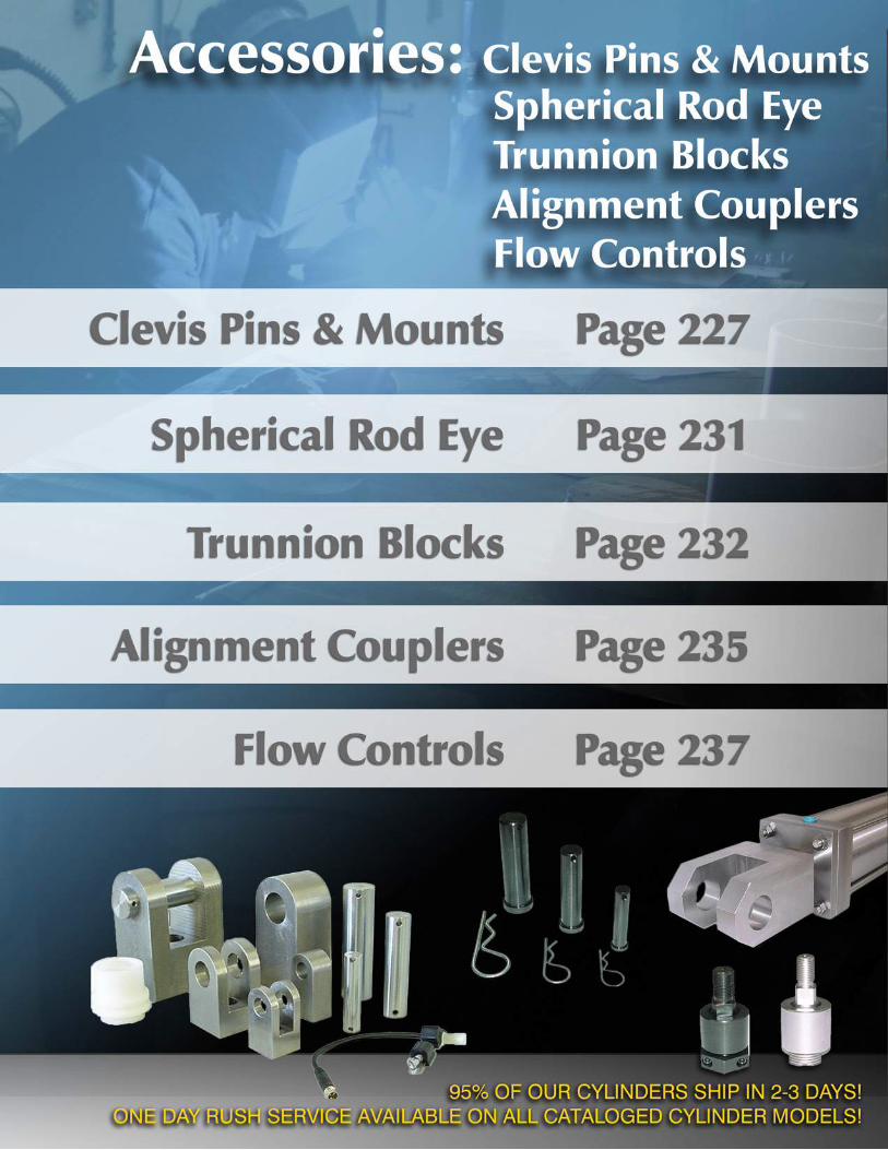
226
FULL COLOR
TAB #13
“ACCESSORIES”

227
ACCESSORIES: CLEVIS, PINS & MOUNTS
Accessories Cross Reference ChartCYLINDER MODEL ACCESSORIES
BOREROD SIZE ROD STYLE (KK)
ROD THREAD
ROD CLEVIS
RODEYE
CLEVISPIN
CLEVISBRACKET
EYEBRACKET
1.50, 2.00, 2.50
0.625 #1 (STANDARD) KK1 7/16 -20 RC437 RE437 CP500
CB500 EB500 #2 KK2 1/2-20 RC500 RE500 CP500
1.000 #1 (ST’D-OVERSIZE) KK1 3/4-16 RC750 RE750 CP750 #4 KK4 1-14 RC1000 RE1000 CP1000
3.25, 4.00, 5.00
1.000 #1 (STANDARD) KK1 3/4-16 RC750 RE750 CP750
CB750 EB750 #4 KK4 1-14 RC1000 RE1000 CP1000
1.375 #1 (ST’D-OVERSIZE) KK1 1-14 RC1000 RE1000 CP1000 #2 KK2 1 1/4 -12 RC1250 N/A CP1375
6.00 & 8.001.375 #1 (STANDARD) KK1 1-14 RC1000 RE1000 CP1000
CB1000 EB1000 #2 KK2 1 1/4 -12 RC1250 N/A CP1375
1.750 #1 (ST’D-OVERSIZE) KK1 1 1/4 -12 RC1250 N/A CP1375 #2 KK2 1 1/2 -12 RC1500 N/A CP1750
10.00 1.750 #1 (STANDARD) KK1 1 1/4 -12 RC1250 RE1250 CP1375 CB1375 EB1375 #2 KK2 1 1/2 -12 RC1500 RE1500 CP1750 CB1750 EB1750
2.000 #1 (STANDARD) KK1 1 1/2 -12 RC1500 RE1500 CP1750 CB1750 EB175012.00 2.000 #1 (STANDARD) KK1 1 1/2 -12 RC1500 RE1500 CP1750 CB1750 EB1750
CLEVIS PIN (WITH BRIDGE PIN - STANDARD)PART NUMBER CD H HP LH LP
CP500 0.500 0.625 0.156 2.250 2.094
CP750 0.750 0.938 0.156 3.000 2.844
CP1000 1.000 1.188 0.203 3.500 3.313
MATERIAL: 1018 CRSFINISH: BLACK OXIDE
CLEVIS PIN (WITH COTTER PINS)
PART NUMBER CD LH LPCP500C 0.500 2.250 1.938
CP750C 0.750 3.000 2.719
CP1000C 1.000 3.500 3.219
CP1375C 1.375 5.000 4.250
CP1750C 1.750 6.000 5.500
CP2000C 2.000 6.000 5.500
MATERIAL: 1045 CRSFINISH: CHROME PLATED O.D.
CLEVIS PIN (WITH E-RINGS)
PART NUMBER CD LH LPCP500E 0.500 2.125 1.875
CP750E 0.750 2.938 2.625
CP1000E 1.000 3.438 3.125
CP1375E 1.375 4.188 4.484
CP1750E 1.750 5.188 5.547
CP2000E 2.000 5.188 5.547
SMALL CLEVIS PIN (WITH BRIDGE PIN)PART NUMBER CD HP LH LP
CP500CCS 0.500 0.156 1.375 1.250
CP750CCS 0.750 0.156 2.000 1.875
SMALL ROD CLEVISPART NUMBER C CB CD CE CH CW KK1 KK2 L
RC437CCS 1.875 0.500 0.500 1.375 1.000 0.250 7/16 -20 — 0.750
RC500CCS 1.875 0.500 0.500 1.375 1.000 0.250 — 1/2-20 0.750
RC750CCS 2.500 0.750 0.750 1.750 1.500 0.375 3/4-16 — 1.000
MATERIAL: 1018 CRSFINISH: BLACK OXIDE
MATERIAL: 1045 CRSFINISH: NITROTECH PLATED*
MATERIAL: 1018 CRSFINISH: BLACK OXIDE
*HARD CHROME PLATED O.D. AVAILABLE
Cle
vis,
Pin
s &
M
ount
sSp
heri
cal R
od
Eyes
Trun
nion
Blo
cks
Alig
nmen
t C
oupl
ers
Flow
Con
trol
sO
ptio
nsPa
ge 1
89Sw
itche
sPa
ge 2
41Te
chni
cal D
ata
Page
277
228
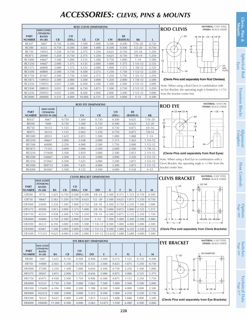
CLEVIS BRACKET DIMENSIONS
PART NUMBER
MAX LOAD (TENSION)
RATED IN LBS BA CB
CD(DIA.) CW DD E F FL L M
CB500 9733 1.625 0.750 0.500 0.500 3/8 -24 2.500 0.375 1.125 0.750 0.500
CB750 18667 2.563 1.250 0.750 0.625 1/2 -20 3.500 0.625 1.875 1.250 0.750
CB1000 25600 3.250 1.500 1.000 0.750 5/8 -18 4.500 0.750 2.250 1.500 1.000
CB1375 49200 3.813 2.000 1.375 1.000 5/8 -18 5.000 0.875 3.000 2.125 1.375
CB1750 45333 4.938 2.500 1.750 1.250 7/8 -14 6.500 0.875 3.125 2.250 1.750
CB2000 44000 5.750 2.500 2.000 1.250 1 -14 7.500 1.000 3.500 2.500 2.000
CB2500 46533 6.594 3.000 2.500 1.500 1 1/8 -12 8.500 1.000 4.000 3.000 2.500
CB3000 45067 7.500 3.000 3.000 1.500 1 1/4 -12 9.500 1.000 4.250 3.250 2.750
CB3500 111333 9.625 4.000 3.500 2.000 1 3/4 -12 12.625 1.688 5.688 4.000 3.500
EYE BRACKET DIMENSIONS
PART NUMBER
MAX LOAD (TENSION)
RATED IN LBS BA CB
CD(DIA.) DD E F FL L M
EB500 5467 1.625 0.750 0.500 0.406 2.500 0.375 1.125 0.750 0.500
EB750 14000 2.563 1.250 0.750 0.531 3.500 0.625 1.875 1.250 0.750
EB1000 27200 3.250 1.500 1.000 0.656 4.500 0.750 2.250 1.500 1.000
EB1375 28267 3.813 2.000 1.375 0.656 5.000 0.875 3.000 2.125 1.375
EB1750 65973 4.938 2.500 1.750 0.906 6.500 0.875 3.125 2.250 1.750
EB2000 93333 5.750 2.500 2.000 1.063 7.500 1.000 3.500 2.500 2.000
EB2500 125600 6.594 3.000 2.500 1.188 8.500 1.000 4.000 3.000 2.500
EB3000 162533 7.500 3.000 3.000 1.313 9.500 1.000 4.250 3.250 2.750
EB3500 76533 9.625 4.000 3.500 1.813 12.625 1.688 5.688 4.000 3.500
EB4000 100000 11.500 4.500 4.000 2.063 14.875 1.938 6.480 4.500 4.000
ROD EYE DIMENSIONS
PART NUMBER
MAX LOAD (TENSION)
RATED IN LBS A CA CBCD
(DIA.)ER
(RADIUS) KKRE437 6667 0.750 1.500 0.750 0.500 0.625 7/16 -20RE500 7600 0.750 1.500 0.750 0.500 0.625 1/2 -20RE750 16133 1.125 2.063 1.250 0.750 0.875 3/4 -16RE875 16133 1.125 2.063 1.250 0.750 0.875 7/8-14
RE1000 28933 1.625 2.813 1.500 1.000 1.888 1 -14RE1250 44667 2.000 3.438 2.000 1.375 1.563 1 1/4 -12RE1500 60000 2.250 4.000 2.500 1.750 2.000 1 1/2-12RE1875 71333 3.000 5.000 2.500 2.000 2.500 1 7/8 -12RE2250 131600 3.500 5.810 3.000 2.500 2.813 2 1/4-12RE2500 146667 3.500 6.125 3.000 3.000 3.250 2 1/2 -12RE3250 215067 4.500 7.625 4.000 3.500 3.875 3 1/4-12RE3500 289733 5.000 7.625 4.000 3.500 3.875 3 1/2 -12RE4000 365067 5.500 9.125 4.500 4.000 4.438 4 -12
ROD CLEVIS DIMENSIONS
PART NUMBER
MAX LOAD (TENSION)
RATED IN LBS CB
CD(DIA.) CE CH CW
ER(RADIUS) KK L
RC437 5667 0.750 0.500 1.500 1.000 0.500 0.500 7/16 -20 0.750RC500 6533 0.750 0.500 1.500 1.000 0.500 0.500 1/2 -20 0.750RC750 14933 1.250 0.750 2.375 1.250 0.625 0.750 3/4 -16 1.250RC875 26000 1.250 0.750 2.375 1.250 0.625 0.750 7/8 -14 1.250
RC1000 44667 1.500 1.000 3.125 1.500 0.750 1.000 1 -14 1.500RC1250 44667 2.000 1.375 4.125 2.000 1.000 1.375 1 1/4 -12 2.125RC1375 60800 2.000 1.375 4.125 2.000 1.000 1.375 1 3/8-12 2.125RC1500 60800 2.500 1.750 4.500 2.375 1.250 1.750 1 1/2-12 2.250RC1750 87467 2.500 1.750 4.500 2.375 1.250 1.750 1 3/4 -12 2.250RC1875 130933 2.500 2.000 5.500 3.000 1.250 2.000 1 7/8 -12 2.500RC2250 130933 3.031 2.500 6.500 3.500 1.500 2.500 2 1/4-12 3.000
RC2500 208933 3.031 3.000 6.750 3.875 1.500 2.750 2 1/2 -12 3.250
RC3250 294933 4.031 3.500 8.500 5.000 2.000 3.500 3 1/4-12 4.000RC4000 200000 4.531 4.000 10.000 6.125 2.250 4.000 4 -12 4.500
ACCESSORIES: CLEVIS, PINS & MOUNTS Clevis, Pins &
M
ountsSpherical Rod
EyesTrunnion Blocks
Alignment
Couplers
Flow C
ontrolsO
ptionsPage 189
Switches
Page 241Technical D
ata Page 277
MATERIAL: CAST STEELFINISH: BLACK OXIDE
MATERIAL: CAST STEELFINISH: BLACK OXIDE
MATERIAL: 1018 CRSFINISH: BLACK OXIDE
MATERIAL: CAST STEELFINISH: BLACK OXIDE
CLEVIS BRACKET
EYE BRACKET
ROD EYE
ROD CLEVIS
Note: When using a Rod Clevis in combination with an Eye Bracket, the operating angle is limited to +/-75O from the bracket center line.
Note: When using a Rod Eye in combination with a Clevis Bracket, the operating angle is +/-90O from the bracket center line.
(Clevis Pins sold separately from Rod Clevises)
229
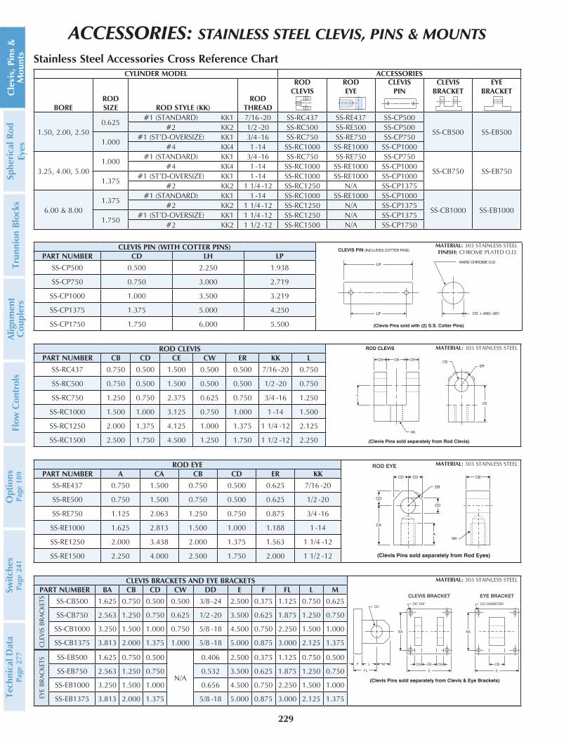
ACCESSORIES: STAINLESS STEEL CLEVIS, PINS & MOUNTS
Stainless Steel Accessories Cross Reference ChartCYLINDER MODEL ACCESSORIES
BOREROD SIZE ROD STYLE (KK)
ROD THREAD
ROD CLEVIS
RODEYE
CLEVISPIN
CLEVISBRACKET
EYEBRACKET
1.50, 2.00, 2.500.625
#1 (STANDARD) KK1 7/16 -20 SS-RC437 SS-RE437 SS-CP500
SS-CB500 SS-EB500 #2 KK2 1/2 -20 SS-RC500 SS-RE500 SS-CP500
1.000 #1 (ST’D-OVERSIZE) KK1 3/4 -16 SS-RC750 SS-RE750 SS-CP750 #4 KK4 1 -14 SS-RC1000 SS-RE1000 SS-CP1000
3.25, 4.00, 5.001.000
#1 (STANDARD) KK1 3/4 -16 SS-RC750 SS-RE750 SS-CP750
SS-CB750 SS-EB750 #4 KK4 1 -14 SS-RC1000 SS-RE1000 SS-CP1000
1.375 #1 (ST’D-OVERSIZE) KK1 1 -14 SS-RC1000 SS-RE1000 SS-CP1000 #2 KK2 1 1/4 -12 SS-RC1250 N/A SS-CP1375
6.00 & 8.001.375
#1 (STANDARD) KK1 1 -14 SS-RC1000 SS-RE1000 SS-CP1000
SS-CB1000 SS-EB1000 #2 KK2 1 1/4 -12 SS-RC1250 N/A SS-CP1375
1.750 #1 (ST’D-OVERSIZE) KK1 1 1/4 -12 SS-RC1250 N/A SS-CP1375 #2 KK2 1 1/2 -12 SS-RC1500 N/A SS-CP1750
CLEVIS PIN (WITH COTTER PINS)PART NUMBER CD LH LP
SS-CP500 0.500 2.250 1.938
SS-CP750 0.750 3.000 2.719
SS-CP1000 1.000 3.500 3.219
SS-CP1375 1.375 5.000 4.250
SS-CP1750 1.750 6.000 5.500
ROD CLEVISPART NUMBER CB CD CE CW ER KK L
SS-RC437 0.750 0.500 1.500 0.500 0.500 7/16 -20 0.750
SS-RC500 0.750 0.500 1.500 0.500 0.500 1/2 -20 0.750
SS-RC750 1.250 0.750 2.375 0.625 0.750 3/4 -16 1.250
SS-RC1000 1.500 1.000 3.125 0.750 1.000 1 -14 1.500
SS-RC1250 2.000 1.375 4.125 1.000 1.375 1 1/4 -12 2.125
SS-RC1500 2.500 1.750 4.500 1.250 1.750 1 1/2 -12 2.250
ROD EYEPART NUMBER A CA CB CD ER KK
SS-RE437 0.750 1.500 0.750 0.500 0.625 7/16 -20
SS-RE500 0.750 1.500 0.750 0.500 0.625 1/2 -20
SS-RE750 1.125 2.063 1.250 0.750 0.875 3/4 -16
SS-RE1000 1.625 2.813 1.500 1.000 1.188 1 -14
SS-RE1250 2.000 3.438 2.000 1.375 1.563 1 1/4 -12
SS-RE1500 2.250 4.000 2.500 1.750 2.000 1 1/2 -12
CLEVIS BRACKETS AND EYE BRACKETSPART NUMBER BA CB CD CW DD E F FL L M
CLE
VIS
BRAC
KETS SS-CB500 1.625 0.750 0.500 0.500 3/8 -24 2.500 0.375 1.125 0.750 0.625
SS-CB750 2.563 1.250 0.750 0.625 1/2 -20 3.500 0.625 1.875 1.250 0.750
SS-CB1000 3.250 1.500 1.000 0.750 5/8 -18 4.500 0.750 2.250 1.500 1.000
SS-CB1375 3.813 2.000 1.375 1.000 5/8 -18 5.000 0.875 3.000 2.125 1.375
EYE
BRAC
KETS SS-EB500 1.625 0.750 0.500
N/A
0.406 2.500 0.375 1.125 0.750 0.500
SS-EB750 2.563 1.250 0.750 0.532 3.500 0.625 1.875 1.250 0.750
SS-EB1000 3.250 1.500 1.000 0.656 4.500 0.750 2.250 1.500 1.000
SS-EB1375 3.813 2.000 1.375 5/8 -18 5.000 0.875 3.000 2.125 1.375
Cle
vis,
Pin
s &
M
ount
sSp
heri
cal R
od
Eyes
Trun
nion
Blo
cks
Alig
nmen
t C
oupl
ers
Flow
Con
trol
sO
ptio
nsPa
ge 1
89Sw
itche
sPa
ge 2
41Te
chni
cal D
ata
Page
277
MATERIAL: 303 STAINLESS STEELFINISH: CHROME PLATED O.D.
MATERIAL: 303 STAINLESS STEEL
MATERIAL: 303 STAINLESS STEEL
MATERIAL: 303 STAINLESS STEEL

MALE SPHERICAL ROD EYE DIMENSIONS
PART NUMBER
BORE (REF.)
RODDIA. A CD CE ER EX JL KK LE
LOADCAPACITY
LBS
HH-MSRE-500 1.500.625
0.688 0.500 0.875 0.875 0.437 0.875 7/16 -20 0.750 26001.000
HH-MSRE-750 2.001.000
1.000 0.750 1.250 1.250 0.656 1.313 3/4 -16 1.063 94001.375
HH-MSRE-750 2.501.000
1.000 0.750 1.250 1.250 0.656 1.313 3/4 -16 1.063 94001.3751.750
HH-MSRE-1000 3.251.375
1.500 1.000 1.875 1.375 0.875 1.500 1 -14 1.438 168001.7502.000
HH-MSRE-1375 4.001.750
2.000 1.375 2.125 1.813 1.188 2.000 1 1/4-12 1.875 285002.0002.500
HH-MSRE-1750 5.00
2.000
2.125 1.750 2.500 2.188 1.531 2.250 1 1/2 -12 2.125 430002.5003.0003.500
HH-MSRE-2000 6.00
2.500
2.875 2.000 2.750 2.625 1.750 2.750 1 7/8 -12 2.500 702003.0003.5004.000
FLANGE END COUPLER DIMENSIONS
PART NUMBER
RODDIA. B C D H I J L M N P
FEC625 0.625 0.406 1.500 0.563 45.0° 90.0° 0.219 4 1.125 0.250 0.656
FEC1000 1.000 0.750 2.000 0.875 30.0° 60.0° 0.281 6 1.500 0.375 1.063
FEC1375 1.375 0.938 2.500 1.000 30.0° 60.0° 0.344 6 2.000 0.375 1.438
FEC1750 1.750 1.188 3.000 1.250 22.5° 45.0° 0.344 8 2.375 0.500 1.813
FEC2000 2.000 1.438 3.500 1.625 15.0° 30.0° 0.406 12 2.688 0.625 2.063
FEC2500 2.500 1.875 4.000 1.875 15.0° 30.0° 0.406 12 3.188 0.750 2.625
FEC3000 3.000 2.375 5.000 2.375 15.0° 30.0° 0.531 12 4.000 0.875 3.125
FEC3500 3.500 2.625 5.875 2.625 15.0° 30.0° 0.656 12 4.688 1.000 3.625
FEC4000 4.000 3.125 6.375 2.625 15.0° 30.0° 0.656 12 5.188 1.000 4.125
FEC4500 4.500 3.625 6.875 3.125 15.0° 30.0° 0.656 12 5.688 1.500 4.625
FEC5000 5.000 4.000 7.375 3.125 15.0° 30.0° 0.656 12 6.188 1.500 5.125
FEC5500 5.500 4.500 8.250 3.875 15.0° 30.0° 0.781 12 6.875 1.875 5.625
WELD PLATE DIMENSIONS
PART NUMBER
RODDIA. E F
G(DIA.) H I K L M
WP625 0.625 0.500 2.000 0.250 45.0° 90.0° 10 -20 4 1.125
WP1000 1.000 0.500 2.500 0.250 30.0° 60.0° 1/4 -20 6 1.500
WP1375 1.375 0.625 3.000 0.250 30.0° 60.0° 5/16 -18 6 2.000
WP1750 1.750 0.625 4.000 0.250 22.5° 45.0° 5/16 -18 8 2.375
WP2000 2.000 0.750 4.000 0.375 15.0° 30.0° 3/8 -16 12 2.688
WP2500 2.500 0.750 4.500 0.375 15.0° 30.0° 3/8 -16 12 3.188
WP3000 3.000 1.000 5.500 0.375 15.0° 30.0° 1/2 -13 12 4.000
WP3500 3.500 1.000 7.000 0.375 15.0° 30.0° 5/8 -11 12 4.688
WP4000 4.000 1.000 7.000 0.375 15.0° 30.0° 5/8 -11 12 5.188
WP4500 4.500 1.000 8.000 0.375 15.0° 30.0° 5/8 -11 12 5.688
WP5000 5.000 1.000 8.000 0.375 15.0° 30.0° 5/8 -11 12 6.188
WP5500 5.500 1.250 9.000 0.375 15.0° 30.0° 3/4 -10 12 6.875
FLANGE END COUPLER
WELD PLATE
MALE SPHERICAL ROD EYE
(To be used withKK10 style rod end)
ACCESSORIES: CLEVIS, PINS & MOUNTS
230
Clevis, Pins &
M
ountsSpherical Rod
EyesTrunnion Blocks
Alignment
Couplers
Flow C
ontrolsO
ptionsPage 189
Switches
Page 241Technical D
ata Page 277

ACCESSORIES: SPHERICAL ROD EYES
231
K
*FITTING
OPTIONAL
G
F
H
CLEVIS
MOUNTED
O
J
A (THREAD)
B
C
D
E
*FITTING
OPTIONAL
G
F
H
CLEVIS
MOUNTED
O
A (THREAD)B
C
D
E
MALE SPHERICAL ROD EYE DIMENSIONS
PART NUMBER A B
C +.0015 -.0005 D E F G H*
STATIC LOAD CAPACITY
LBS
APPROX. WEIGHT
LBSMSRE-437 7/16 -20 1.500 0.5000 0.500 0.625 1.313 2.438 12 6,660 .25
MSRE-500 1/2 -20 1.500 0.5000 0.500 0.625 1.313 2.438 12 6,660 .25
MSRE-750 3/4 -16 1.750 0.7500 0.688 0.875 1.750 2.875 14 11,515 .60
MSRE-1000 1 -14 2.125 1.0000 1.000 1.375 2.750 4.125 17 43,540 2.125
MSRE-1250 1 1/4 -12 2.125 1.0000 1.000 1.375 2.750 4.125 17 43,540 2.413
* Consult factory for delivery.
FEMALE SPHERICAL ROD EYE DIMENSIONS
PART NUMBER A B
C +.0015 -.0005 D E F G H* J K
STATIC LOAD CAPACITY
LBS
APPROX. WEIGHT
LBSFSRE-312* 5/16 -24 0.750 0.3125 0.340 0.438 0.875 1.375 14 0.437 0.500 3,130 .09
FSRE-437 7/16 -20 1.188 0.5000 0.500 0.625 1.313 2.125 12 0.750 0.875 6,660 .33
FSRE-500 1/2 -20 1.188 0.5000 0.500 0.625 1.313 2.125 12 0.750 0.875 6,660 .33
FSRE-750 3/4 -16 1.750 0.7500 0.688 0.875 1.750 2.875 14 1.000 1.125 11,515 .72
FSRE-1000 1 -14 2.125 1.0000 1.000 1.375 2.750 4.125 17 1.500 1.625 43,540 2.413
FSRE-1250* 1 1/4 -12 2.125 1.0000 1.000 1.375 2.750 4.125 17 1.500 1.625 43,540 2.413
Assortment of Female Spherical Rod Eyes.
Assortment of Male Spherical Rod Eyes.
Cle
vis,
Pin
s &
M
ount
sSp
heri
cal R
od
Eyes
Trun
nion
Blo
cks
Alig
nmen
t C
oupl
ers
Flow
Con
trol
sO
ptio
nsPa
ge 1
89Sw
itche
sPa
ge 2
41Te
chni
cal D
ata
Page
277
MALE SPHERICAL ROD EYE
FEMALE SPHERICAL ROD EYE

ACCESSORIES: TRUNNION BLOCKS
232
TRD is making it easier to set up trunnion style actuation solutions. TRD now offers mountable trunnion supports for 1.50” to 8.00” bore trunnion mounts. The TB-1000 support will take all 1.50” to 5.00” bores and the TB-1375 support will fit 6.00” and 8.00” bores. Trunnion blocks are available in aluminum and stainless steel constructions.
All supports feature IGNUS® “High-Load” bearings as standard. These bearings are made of T-500 composite which provide over ten times the strength of bronze bushings for heavy-duty performance and long life. T-500 is rated for intermittent food and wash down applications.
Trunnion supports can be used with all NFPA mounts MT1, MT2 and MT4, as well as TRD solid one-piece steel trunnion styles MT1S and MT2S. All trunnion blocks are in stock and available for immediate order.
Contact Factory for delivery for large orders or special requirements.
TRUNNION BLOCK ORDERING INFORMATION
PART NUMBER BORE SIZE BLOCK MATERIAL BEARING MATERIAL
TB-1000 1.50 to 5.00 Aluminum w/ Black Anodize T-500 Composite
TB-1375 6.00 to 8.00 Aluminum w/ Black Anodize T-500 Composite
SS-TB-1000 1.50 to 5.00 303 Stainless Steel T-500 Composite
SS-TB-1375 6.00 to 8.00 303 Stainless Steel T-500 Composite
All above part numbers are for a pair of trunnion blocks. To order a single trunnion block, add -1 to the end of the part number (example: TB-1000-1). Note: fasteners not supplied.
REPLACEMENT BEARING ORDERING INFORMATION
PART NUMBERQTY REQUIRED PER
TRUNNIONREPLACEMENT FOR TRUNNION
BLOCK SERIES BEARING MATERIAL
TB-30-1 1 TB-1000 and SS-TB-1000 T-500 Composite
TB-30-2 2 TB-1375 and SS-TB-1375 T-500 Composite
Aluminum trunnion blocks TB-1000 and TB-1375 with T-500 composite bearings. Stainless Steel trunnion block SS-TB-1000 with T-500 composite bearings.
Clevis, Pins &
M
ountsSpherical Rod
EyesTrunnion Blocks
Alignment
Couplers
Flow C
ontrolsO
ptionsPage 189
Switches
Page 241Technical D
ata Page 277

ACCESSORIES: TRUNNION BLOCKS
233
BORE PART NUMBER A TD E EF X CS* TM Y
1.50 TB-1000 2.375 1.000 2.000 0.563 3.125 0.500 2.500 3.625
2.00 TB-1000 2.375 1.000 2.500 0.563 3.625 0.500 3.000 4.125
2.50 TB-1000 2.375 1.000 3.000 0.563 4.125 0.500 3.500 4.625
3.25 TB-1000 2.375 1.000 3.750 0.563 4.875 0.500 4.500 5.625
4.00 TB-1000 2.375 1.000 4.500 0.563 5.625 0.500 5.250 6.375
5.00 TB-1000 2.375 1.000 5.500 0.563 6.625 0.500 6.250 7.375
6.00 TB-1375 4.000 1.375 6.500 1.078 8.656 0.750 7.625 9.781
8.00 TB-1375 4.000 1.375 8.500 1.078 10.656 0.750 9.750 11.906
* Recommended cap screw size (cap screws not supplied).
* BEARING FLANGE ON BOTH
SIDES ON TB-1375-1 ONLY
TD DIA.
C
A/2
A
B
G DIA. THRU
H C’BORE X J DEEP
E/2
* F
D
FE
STANDARD ALUMINUM TRUNNION BLOCKS WITH BEARING
PART NUMBER A B C D E F G H J TB
TB-1000-1 2.375 3.375 1.000 2.000 1.000 0.062 0.531 0.797 0.531 1.000
TB-1375-1 4.000 5.500 1.500 3.000 2.000 0.078 0.781 1.187 0.781 1.375
Cle
vis,
Pin
s &
M
ount
sSp
heri
cal R
od
Eyes
Trun
nion
Blo
cks
Alig
nmen
t C
oupl
ers
Flow
Con
trol
sO
ptio
nsPa
ge 1
89Sw
itche
sPa
ge 2
41Te
chni
cal D
ata
Page
277
NOTE: SHOWN WITH BEARING FLANGES ON INSIDE OF BLOCKS FACING CYLINDER.
MT1/MT2
HEAD & CAP TRUNNION
MOUNTING DIMENSIONS
E
CS A
BEARING
FLANGES
TD DIA.
CS A
TD DIA.
MT4
INTERMEDIATE TRUNNION
MOUNTING DIMENSIONS
X
.000
+.030
EF
Y
.000
+.030
EF
TM

ACCESSORIES: TRUNNION BLOCKS
234
* BEARING FLANGE ON BOTH
SIDES ON SS-TB-1375-1 ONLY
TD DIA.
C
K
A/2
A
B
L M
G DIA. THRU
E/2
* F
D
FE
STAINLESS STEEL TRUNNION BLOCKS WITH BEARING
PART NUMBER A B C D E F G K L M TD
SS-TB-1000-1 2.375 3.375 1.000 2.000 1.000 0.062 0.531 1.469 1.250 1.063 1.000
SS-TB-1375-1 4.000 5.500 1.500 3.000 2.000 0.078 0.781 2.219 2.125 1.688 1.375
Clevis, Pins &
M
ountsSpherical Rod
EyesTrunnion Blocks
Alignment
Couplers
Flow C
ontrolsO
ptionsPage 189
Switches
Page 241Technical D
ata Page 277

How to Order:
MATERIAL: 100,000 MIN. YIELD STRESS-PROOFFINISH: BLACK OXIDE
OR MATERIAL: 303 STAINLESS STEEL
ACCESSORIES: ALIGNMENT COUPLERSBenefits• Rod alignment couplers eliminate expensive machining for mounting fixed or rigid cylinders
on guided or slide applications.
• Cylinder efficiency is increased by eliminating friction caused by misalignment. Couplers compensate for 1° angular error and .06” lateral misalignment on push or pull strokes.
• Couplers provide greater reliability, performance and reduce cylinder component wear.
• Simplifies alignment problems in the field.
Design Tips• Alignment couplers can be exposed to high
stresses that are not apparent in an application. Always use the largest thread size practical in your application (see chart for maximum pull yields).
• Use jam nut to lock coupler to rod when used with full diameter threads (example: 0.625” thread on 0.625” rod).
• Large thread sizes can be pinned in high impact applications, eliminating unwanted loosening of coupler from rod. Always use the smallest pin possible to avoid weakening the piston rod thread (example: Use a 0.090” diameter pin for 0.625” rod threads and larger).
Standard AC CouplerAC250 - AC5000
Metric AC CouplerMAC250-M4x0.7 - MAC750-M20x1.5
ACH CouplerACH250 - ACH1250
(Optional alternative size*)
AC 250 - 312 FEMALE
SERIESAC
ACH
SIZE250312375437500625750875
10001250137515001750
SIZE25031237543750062575087510001250137515001750
* You can order different thread sizes within the same size of coupler housing DIA. (refer to “B” Diameter in dimension chart).
Recommended maximum stroke for cylinders with
alignment couplers in horizontal applications
BOREMAXIMUM
STROKE1.50 27
2.00 43
2.50 50
3.25 50
4.00 55
5.00 55
6.00 55
8.00 55Ordering Examples:AC250 (AC with male & female 1/4 -28 thread)ACH500 (ACH with male & female 1/2 -20 thread)AC437-625 FEMALE (AC with 7/16 -20 male and 5/8 -18 female thread)
Stainless Steel Standard AC Coupler
SS-AC250 - SS-AC1500
235
Cle
vis,
Pin
s &
M
ount
sSp
heri
cal R
od
Eyes
Trun
nion
Blo
cks
Alig
nmen
t C
oupl
ers
Flow
Con
trol
sO
ptio
nsPa
ge 1
89Sw
itche
sPa
ge 2
41Te
chni
cal D
ata
Page
277
METRIC ROD ALIGNMENT COUPLERS (STEEL)
PART NUMBER A B C D E F G HMAX PULL POUNDS
(3:1 SAFETY FACTOR)
MAC250-M4x0.7 M4x0.7 1.125 1.750 .375 .500 .500 .375 .687 251
MAC250-M6x1.0 M6x1.0 1.125 1.750 .375 .500 .500 .375 .687 687
MAC312-M8x1.25 M8x1.25 1.125 1.750 .375 .500 .500 .375 .687 1,349
MAC437-M10x1.25 M10x1.25 1.250 2.000 .437 .750 .625 .500 .812 2,435
MAC500-M12x1.25 M12x1.25 1.250 2.000 .437 .750 .625 .500 .812 3,860
MAC625-M16x1.5 M16x1.5 1.250 2.000 .437 .750 .625 .500 .812 7,299
MAC750-M20x1.5 M20x1.5 1.750 2.312 .437 1.125 .968 .812 1.125 12,537
METRIC ROD AC SERIES

ACH SERIESAC SERIES
ALIGNMENT COUPLER DIMENSIONSPART
NUMBER A B C D E F G H H HEX JMAX PULL POUNDS(3:1 SAFETY FACTOR)
AC250 1/4 -28 1.125 1.750 0.375 0.500 0.500 0.375 0.688 1.250 2.000 886AC312 5/16 -24 1.125 1.750 0.375 0.500 0.500 0.375 0.688 1.250 2.000 1,623AC375 3/8 -24 1.125 1.750 0.375 0.500 0.500 0.375 0.688 1.250 2.000 2,532AC437 7/16 -20 1.250 2.000 0.438 0.750 0.625 0.500 0.813 1.250 2.156 3,526AC500 1/2 -20 1.250 2.000 0.438 0.750 0.625 0.500 0.813 1.250 2.156 4,841AC625 5/8 -18 1.250 2.000 0.438 0.750 0.625 0.500 0.813 1.250 2.156 7,862AC750 3/4 -16 1.750 2.313 0.438 1.125 0.969 0.813 1.125 1.750 2.500 11,543AC875 7/8 -14 1.750 2.313 0.438 1.125 0.969 0.813 1.125 1.750 2.500 15,846AC1000 1 -14 2.500 2.938 0.438 1.625 1.344 1.156 1.625 2.500 2.938 21,206AC1250 1 1/4 -12 2.500 2.938 0.438 1.625 1.344 1.156 1.625 2.500 2.938 34,024AC1375 1 3/8 -12 2.500 2.938 0.438 1.625 1.344 1.156 1.625 — — 40,710AC1500 1 1/2 -12 3.250 4.375 0.875 2.250 1.969 1.750 2.375 — — 49,857AC1750 1 3/4 -12 3.250 4.375 0.875 2.250 1.969 1.750 2.375 — — 69,558AC1875 1 7/8 -12 3.750 5.625 1.000 3.000 2.469 2.125 2.750 — — 79,354AC2000 2 -12 3.750 5.625 1.000 3.000 2.469 2.125 2.750 — — 92,531AC2250 2 1/4 -12 4.500 6.375 1.000 3.500 2.969 2.625 3.375 — — 118,776AC2500 2 1/2 -12 5.000 6.563 1.000 3.500 3.938
SPANNER
HOLES
— — 149,543AC2750 2 3/4 -12 5.000 6.563 1.000 3.500 3.938 — — 182,464AC3000 3 -12 5.000 6.563 1.000 3.500 3.938 — — 218,658AC3250 3 1/4 -12 6.250 8.125 1.000 4.500 4.938 — — 258,124AC3500 3 1/2 -12 6.250 8.125 1.000 4.500 4.938 — — 300,863AC3750 3 3/4 -12 6.250 8.125 1.000 4.500 4.938 — — 346,875AC4000 4 -12 7.500 9.500 1.000 5.500 5.938 — — 396,158AC4500 4 1/2 -12 7.500 9.500 1.000 5.500 5.938 — — 504,544AC5000 5 -12 7.500 9.500 1.000 5.500 5.938 — — 626,019
* Please specify AC or ACH coupler when ordering: i.e.: AC750 (Std. Coupler) or ACH750 (Hex Coupler).**Spanner holes are used on AC2250 and larger, Two (2) 0.500” diameter holes, 0.500” deep, 180° apart (each end).
ACCESSORIES: ALIGNMENT COUPLERS
STAINLESS STEEL ALIGNMENT COUPLERSALIGNMENT COUPLERS - STAINLESS STEEL
PART NUMBER A B C D E F G HMAX PULL POUNDS
(3:1 SAFETY FACTOR)
SS-AC250 1/4 -28 1.125 1.750 0.375 0.500 0.500 0.375 0.688 310SS-AC312 5/16 -24 1.125 1.750 0.375 0.500 0.500 0.375 0.688 568SS-AC375 3/8 -24 1.125 1.750 0.375 0.500 0.500 0.375 0.688 886SS-AC437 7/16 -20 1.250 2.000 0.438 0.750 0.625 0.500 0.813 1,234SS-AC500 1/2 -20 1.250 2.000 0.438 0.750 0.625 0.500 0.813 1,694SS-AC625 5/8 -18 1.250 2.000 0.438 0.750 0.625 0.500 0.813 2,752SS-AC750 3/4 -16 1.750 2.313 0.438 1.125 0.969 0.813 1.125 4,040SS-AC875 7/8 -14 1.750 2.313 0.438 1.125 0.969 0.813 1.125 5,546
SS-AC1000 1 -14 2.500 2.938 0.438 1.625 1.344 1.156 1.625 7,422SS-AC1250 1 1/4 -12 2.500 2.938 0.438 1.625 1.344 1.156 1.625 11,908SS-AC1500 1 1/2 -12 3.250 4.375 0.875 2.250 1.969 1.750 2.375 17,450
236
Clevis, Pins &
M
ountsSpherical Rod
EyesTrunnion Blocks
Alignment
Couplers
Flow C
ontrolsO
ptionsPage 189
Switches
Page 241Technical D
ata Page 277

ACCESSORIES: FLOW CONTROLS (FCP SERIES)
FCP4 FCP4K FCP4L For 1/4” port
Materials:Banjo Connector: Chrome plated, zinc die cast
Banjo Retaining Ring: Zinc plated steel
Stem: High strength anodized aluminum alloy
Adjusting Needle: Stainless steel
“O” Rings and Lip Seal: Buna N
Maximum Operating Pressure: 150 PSI Air Only
Operating Temperature Range: -20°F to +200°F (-25°C to +95°C)
PORT SIZE0.250”, 0.375”, 0.500”
1/4 NPT
.75
1/4 NPT
RECESSED
0.75
2.35
7/16 HEXNUT
11/16 HEX
2.89MAX.
1.36
(L) LOCK NUT OPTION
DRY SEALANT ON THREADS
2.87MAX.
(K) KNOB OPTION
FCP6 FCP6K FCP6L For 3/8” port
FCP8 FCP8K FCP8L For 1/2” port
3.02MAX.
3/8 NPT
0.80
3/8 NPT
RECESSED
0.97
2.46
9/16 HEXNUT
7/8 HEX
3.02MAX.
1.63
(L) LOCK NUT OPTION
DRY SEALANT ON THREADS
(K) KNOB OPTION
5/8 HEXNUT
1-1/8 HEX
3.89MAX.
2.12
(L) LOCK NUT OPTION
1/2 NPT
0.97
1/2 NPT
RECESSED
1.25
3.16
3.89MAX.
DRY SEALANT ON THREADS
(K) KNOB OPTION
237
Cle
vis,
Pin
s &
M
ount
sSp
heri
cal R
od
Eyes
Trun
nion
Blo
cks
Alig
nmen
t C
oupl
ers
Flow
Con
trol
sO
ptio
nsPa
ge 1
89Sw
itche
sPa
ge 2
41Te
chni
cal D
ata
Page
277
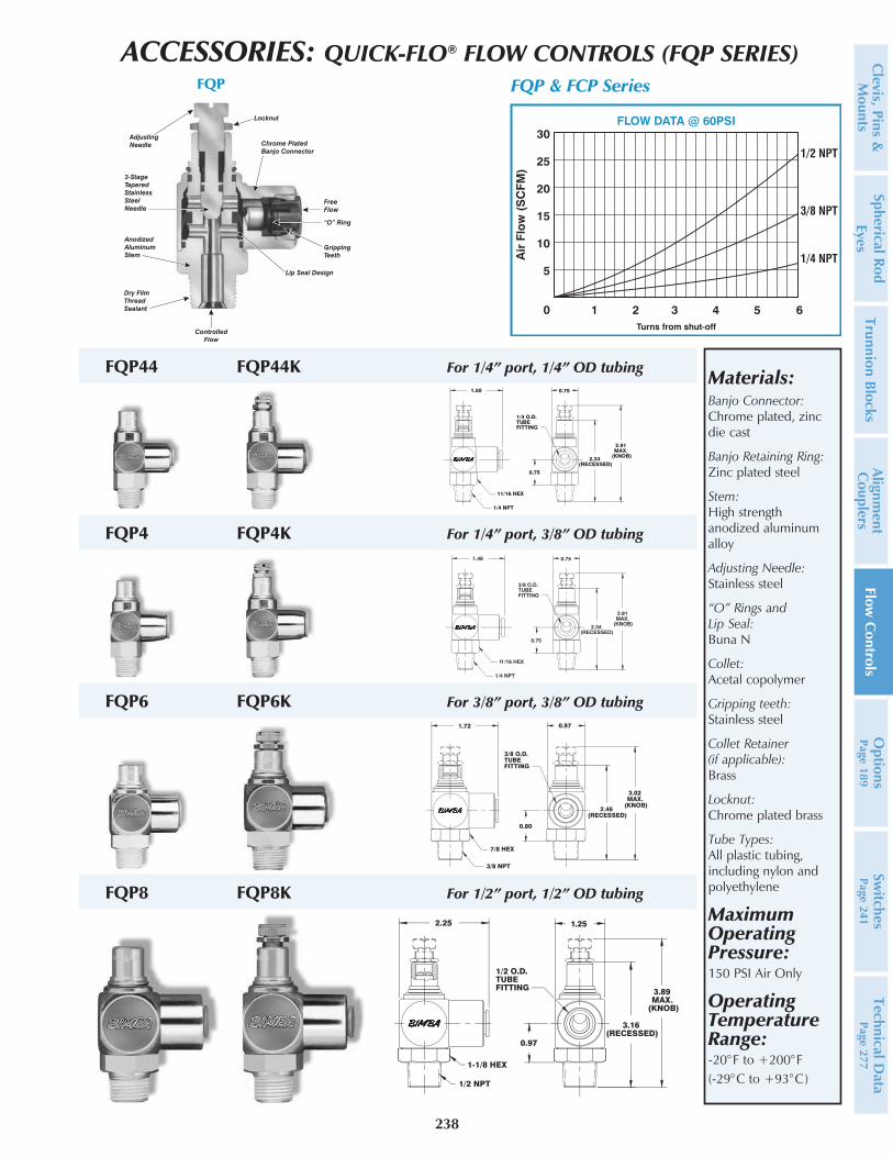
ACCESSORIES: QUICK-FLO® FLOW CONTROLS (FQP SERIES)
Materials:Banjo Connector: Chrome plated, zinc die cast
Banjo Retaining Ring: Zinc plated steel
Stem: High strength anodized aluminum alloy
Adjusting Needle: Stainless steel
“O” Rings and Lip Seal: Buna N
Collet: Acetal copolymer
Gripping teeth: Stainless steel
Collet Retainer (if applicable): Brass
Locknut: Chrome plated brass
Tube Types: All plastic tubing, including nylon and polyethylene
Maximum Operating Pressure: 150 PSI Air Only
Operating Temperature Range: -20°F to +200°F (-29°C to +93°C)
FQP44 FQP44K For 1/4” port, 1/4” OD tubing
FQP4 FQP4K For 1/4” port, 3/8” OD tubing
FQP6 FQP6K For 3/8” port, 3/8” OD tubing
FQP8 FQP8K For 1/2” port, 1/2” OD tubing
238
Clevis, Pins &
M
ountsSpherical Rod
EyesTrunnion Blocks
Alignment
Couplers
Flow C
ontrolsO
ptionsPage 189
Switches
Page 241Technical D
ata Page 277


