NREL is a national laboratory of the U.S. Department of Energy Office of Energy Efficiency & Renewable Energy Operated by the Alliance for Sustainable Energy, LLC This report is available at no cost from the National Renewable Energy Laboratory (NREL) at www.nrel.gov/publications. Contract No. DE-AC36-08GO28308 Conference Paper NREL/CP-5000-77123 October 2020 Functional Requirements for the WEIS Toolset to Enable Controls Co-Design of Floating Offshore Wind Turbines Preprint Jason Jonkman, 1 Alan Wright, 1 Garrett Barter, 1 Matthew Hall, 1 James Allison, 2 and Daniel R. Herber 3 1 National Renewable Energy Laboratory 2 University of Illinois Urbana-Champaign 3 Colorado State University Presented at ASME 2020 3 rd International Offshore Wind Technical Conference February 16-17, 2021
Transcript
NREL is a national laboratory of the U.S. Department of Energy Office of Energy Efficiency & Renewable Energy Operated by the Alliance for Sustainable Energy, LLC This report is available at no cost from the National Renewable Energy Laboratory (NREL) at www.nrel.gov/publications.
Contract No. DE-AC36-08GO28308
Conference Paper NREL/CP-5000-77123 October 2020
Functional Requirements for the WEIS Toolset to Enable Controls Co-Design of Floating Offshore Wind Turbines PreprintJason Jonkman,1 Alan Wright,1 Garrett Barter,1 Matthew Hall,1 James Allison,2 and Daniel R. Herber3
1 National Renewable Energy Laboratory 2 University of Illinois Urbana-Champaign3 Colorado State University
Presented at ASME 2020 3rd International Offshore Wind Technical Conference February 16-17, 2021
NREL is a national laboratory of the U.S. Department of Energy Office of Energy Efficiency & Renewable Energy Operated by the Alliance for Sustainable Energy, LLC This report is available at no cost from the National Renewable Energy Laboratory (NREL) at www.nrel.gov/publications.
Contract No. DE-AC36-08GO28308
National Renewable Energy Laboratory 15013 Denver West Parkway Golden, CO 80401 303-275-3000 • www.nrel.gov
Conference Paper NREL/CP-5000-77123 October 2020
Functional Requirements for the WEIS Toolset to Enable Controls Co-Design of Floating Offshore Wind Turbines PreprintJason Jonkman,1 Alan Wright,1 Garrett Barter,1 Matthew Hall,1 James Allison,2 and Daniel R. Herber3
1 National Renewable Energy Laboratory 2 University of Illinois Urbana-Champaign3 Colorado State University
Suggested Citation Jonkman, Jason, Alan Wright, Garrett Barter, Matthew Hall, James Allison, Daniel R. Herber. 2020. Functional Requirements for the WEIS Toolset to Enable Controls Co-Design of Floating Offshore Wind Turbines: Preprint. Golden, CO: National Renewable Energy Laboratory. NREL/CP-5000-77123. https://www.nrel.gov/docs/fy21osti/77123.pdf.
This work was authored [in part] by the National Renewable Energy Laboratory, operated by Alliance for Sustainable Energy, LLC, for the U.S. Department of Energy (DOE) under Contract No. DE-AC36-08GO28308. Funding provided by the U.S. Department of Energy Advanced Research Projects Agency – Energy ( ARPA-E). The views expressed herein do not necessarily represent the views of the DOE or the U.S. Government. The U.S. Government retains and the publisher, by accepting the article for publication, acknowledges that the U.S. Government retains a nonexclusive, paid-up, irrevocable, worldwide license to publish or reproduce the published form of this work, or allow others to do so, for U.S. Government purposes.
This report is available at no cost from the National Renewable Energy Laboratory (NREL) at www.nrel.gov/publications.
U.S. Department of Energy (DOE) reports produced after 1991 and a growing number of pre-1991 documents are available free via www.OSTI.gov.
Cover Photos by Dennis Schroeder: (clockwise, left to right) NREL 51934, NREL 45897, NREL 42160, NREL 45891, NREL 48097, NREL 46526.
NREL prints on paper that contains recycled content.
This report is available at no cost from the National Renewable Energy Laboratory (NREL) at www.nrel.gov/publications.
FUNCTIONAL REQUIREMENTS FOR THE WEIS TOOLSET TO ENABLE CONTROLS CO-DESIGN OF FLOATING OFFSHORE WIND TURBINES
Jason Jonkman1, Alan Wright, Garrett Barter, Matthew Hall National Renewable Energy Laboratory
Golden, Colorado (USA)
James Allison University of Illinois Urbana-Champaign
Champaign, Illinois (USA)
Daniel R. Herber Colorado State University
Fort Collins, Colorado (USA)
ABSTRACT The goal of the new Wind Energy with Integrated Servo-
control (WEIS) toolset under development is to provide the offshore wind industry and research communities with an open-source, user-friendly, flexible tool to enable true controls co-design (CCD) of the physical design of a floating offshore wind turbine together with the controller. WEIS will use a multifidelity library of models built on the foundations of WISDEM® and OpenFAST (formerly known as FAST). This paper presents the WEIS development plan, including the functional requirements of WEIS (including improvements to WISDEM and OpenFAST) together with associated rationale for their establishment and a qualitative description of the modeling approaches that will be implemented to address these functional requirements. The development of WEIS is a project under the Aerodynamic Turbines Lighter and Afloat with Nautical Technologies and Integrated Servo-control program funded by the U.S. Department of Energy Advanced Research Projects Agency – Energy.
1. INTRODUCTIONMost floating offshore wind turbines (FOWTs) have been
designed in a sequential manner, with the controller being designed and optimized toward the end of the design process. Treating the controller design as an add-on to the constituent component designs does not capitalize on the inherent design coupling between the system dynamics and controller behavior, resulting in suboptimal system designs [1]. The goal in controls co-design (CCD) is to bring all components, including the controller, together in a concurrent design and optimization approach that properly accounts for this coupling. CCD will be
critical to realizing FOWT cost reductions that will position offshore wind as highly competitive with other energy sources.
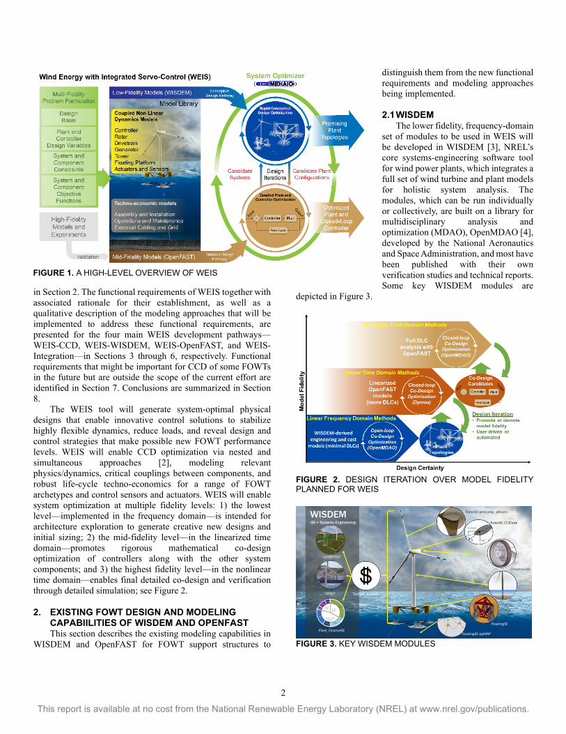
The Aerodynamic Turbines Lighter and Afloat with Nautical Technologies and Integrated Servo-control (ATLANTIS) program funded by the U.S. Department of Energy (DOE) Advanced Research Projects Agency-Energy (ARPA-E) seeks to develop new technology pathways for the design of economically competitive FOWTs. Within ATLANTIS Topic Area 2 (Computer Tools), the National Renewable Energy Laboratory (NREL) and collaborators from the University of Illinois Urbana-Champaign and Colorado State University have been awarded a project that will develop the Wind Energy with Integrated Servo-control (WEIS) toolset, with the goal of providing the offshore wind industry and research communities with an open-source, user-friendly, flexible tool to enable true CCD of the FOWT physical design together with the controller. WEIS will use a multifidelity library of models built on the foundations of the Wind-Plant Integrated System Design & Engineering Model (WISDEM®) and OpenFAST (formerly known as FAST), developed by NREL via support from DOE; see Figure 1. WISDEM and OpenFAST will remain distinct software (which will be improved in the WEIS project), with WEIS as a new, independent software that combines WISDEM, OpenFAST, and CCD functionality for FOWT not previously possible.
This paper presents the WEIS development plan needed to progress to detailed planning and implementation in source code. A summary of the existing physics and techno-economic modeling capabilities of WISDEM and OpenFAST is provided
2
This report is available at no cost from the National Renewable Energy Laboratory (NREL) at www.nrel.gov/publications.
in Section 2. The functional requirements of WEIS together with associated rationale for their establishment, as well as a qualitative description of the modeling approaches that will be implemented to address these functional requirements, are presented for the four main WEIS development pathways—WEIS-CCD, WEIS-WISDEM, WEIS-OpenFAST, and WEIS-Integration—in Sections 3 through 6, respectively. Functional requirements that might be important for CCD of some FOWTs in the future but are outside the scope of the current effort are identified in Section 7. Conclusions are summarized in Section 8.
The WEIS tool will generate system-optimal physical designs that enable innovative control solutions to stabilize highly flexible dynamics, reduce loads, and reveal design and control strategies that make possible new FOWT performance levels. WEIS will enable CCD optimization via nested and simultaneous approaches [2], modeling relevant physics/dynamics, critical couplings between components, and robust life-cycle techno-economics for a range of FOWT archetypes and control sensors and actuators. WEIS will enable system optimization at multiple fidelity levels: 1) the lowest level—implemented in the frequency domain—is intended for architecture exploration to generate creative new designs and initial sizing; 2) the mid-fidelity level—in the linearized time domain—promotes rigorous mathematical co-design optimization of controllers along with the other system components; and 3) the highest fidelity level—in the nonlinear time domain—enables final detailed co-design and verification through detailed simulation; see Figure 2.
2. EXISTING FOWT DESIGN AND MODELING CAPABIILITIES OF WISDEM AND OPENFAST
This section describes the existing modeling capabilities in WISDEM and OpenFAST for FOWT support structures to
distinguish them from the new functional requirements and modeling approaches being implemented.
2.1 WISDEM The lower fidelity, frequency-domain set of modules to be used in WEIS will be developed in WISDEM [3], NREL’s core systems-engineering software tool for wind power plants, which integrates a full set of wind turbine and plant models for holistic system analysis. The modules, which can be run individually or collectively, are built on a library for multidisciplinary analysis and optimization (MDAO), OpenMDAO [4], developed by the National Aeronautics and Space Administration, and most have been published with their own verification studies and technical reports. Some key WISDEM modules are
depicted in Figure 3.
FIGURE 2. DESIGN ITERATION OVER MODEL FIDELITY PLANNED FOR WEIS
FIGURE 3. KEY WISDEM MODULES
WISDEM(SE = Systems Engineering)
Plant_FinanceSE
ORBIT
FloatingSE-pyMAP
FloatingSE
TowerSE
DrivetrainSE
RotorSE-CCBlade
RotorSE-preComp, pBeam
LandBOSSE
Turbine_CostsSE
32.90%
1.40%1.80%
13.90%0.50%9%
19%
0.50%4.50%
8.70%
6.40%1%
Turbines, 32.50%
Balace of System, 46.20%
Financial, 20.50%
FIGURE 1. A HIGH-LEVEL OVERVIEW OF WEIS
3
This report is available at no cost from the National Renewable Energy Laboratory (NREL) at www.nrel.gov/publications.
The status of WISDEM capabilities as they relate to the CCD of FOWTs is as follows: • Design load cases (DLCs): WISDEM is currently a steady-
state analysis code, so DLCs are defined differently than the traditional interpretation. Each module is typically hard-coded to analyze the DLC that drives the design for the given component.
• Aerodynamics: WISDEM calculates steady-state aerodynamic loading through its RotorSE model and blade-element/momentum (BEM) solver.
• Hydrodynamics: WISDEM, through its FloatingSE module, currently computes only hydrostatic loads and rigid-body modes.
• Structural dynamics: WISDEM models the full turbine support structure with Frame3DD, an open-source static and dynamic structural analysis of two-dimensional (2D) and three-dimensional (3D) frames and trusses with elastic and geometric stiffness. Blade elastic properties are computed by PreComp and structural response by pBeam. Mooring loading and dynamics are computed with MAP++, an in-house NREL quasi-static tool.
• Control: As a steady-state model, there is no controller currently in WISDEM.
• Drivetrain: WISDEM models turbine drivetrains through its DrivetrainSE module, which allows for sizing and costing of key nacelle components in geared or direct-drive configurations. This includes sizing of the hub, shaft(s), bearings, gearbox (if any), generator, yaw drive, and bedplate. Although most components are modeled with simple scaling laws, the generator tool allows for structural and electromagnetic optimization of the design.
• Turbine cost models: The WISDEM component cost models offer two levels of complexity: first, all components have an empirically derived scaling between the total mass and total cost (commonly referred to as the NREL Cost and Scaling Model); second, many component models have implemented a “bottom-up” cost model that tallies the bill of materials and total labor hours. This second approach allows for better scaling and modeling of technology innovations.
• Plant cost models: To capture plant life-cycle costs, WISDEM includes modules for all the costs incurred to an offshore plant owner/operator beyond the turbine capital cost. This includes the balance-of-station costs associated with permitting, surveys, assembly, vessel rental, installation, cabling, and commissioning. NREL recently undertook an overhaul of this module to rework it as a bottom-up approach as well, and it is now referred to as Offshore Renewables Balance-of-system Installation Tool (ORBIT). Plant_FinanceSE, another WISDEM module, assembles all costs and energy production performance to compute levelized cost of energy.
• FLOw Redirection and Induction in Steady State (FLORIS): An important consideration in estimating offshore wind plant energy production is wake losses. WISDEM relies on
the steady-state FLORIS code, which provides a family of wake models, to estimate wake losses.
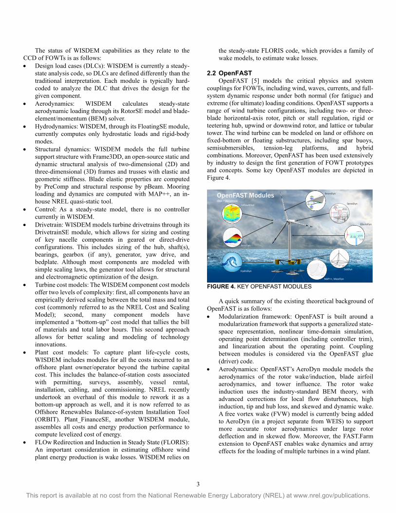
2.2 OpenFAST OpenFAST [5] models the critical physics and system
couplings for FOWTs, including wind, waves, currents, and full-system dynamic response under both normal (for fatigue) and extreme (for ultimate) loading conditions. OpenFAST supports a range of wind turbine configurations, including two- or three-blade horizontal-axis rotor, pitch or stall regulation, rigid or teetering hub, upwind or downwind rotor, and lattice or tubular tower. The wind turbine can be modeled on land or offshore on fixed-bottom or floating substructures, including spar buoys, semisubmersibles, tension-leg platforms, and hybrid combinations. Moreover, OpenFAST has been used extensively by industry to design the first generation of FOWT prototypes and concepts. Some key OpenFAST modules are depicted in Figure 4.
FIGURE 4. KEY OPENFAST MODULES
A quick summary of the existing theoretical background of
OpenFAST is as follows: • Modularization framework: OpenFAST is built around a
modularization framework that supports a generalized state-space representation, nonlinear time-domain simulation, operating point determination (including controller trim), and linearization about the operating point. Coupling between modules is considered via the OpenFAST glue (driver) code.
• Aerodynamics: OpenFAST’s AeroDyn module models the aerodynamics of the rotor wake/induction, blade airfoil aerodynamics, and tower influence. The rotor wake induction uses the industry-standard BEM theory, with advanced corrections for local flow disturbances, high induction, tip and hub loss, and skewed and dynamic wake. A free vortex wake (FVW) model is currently being added to AeroDyn (in a project separate from WEIS) to support more accurate rotor aerodynamics under large rotor deflection and in skewed flow. Moreover, the FAST.Farm extension to OpenFAST enables wake dynamics and array effects for the loading of multiple turbines in a wind plant.
OpenFAST Modules(Dyn = Dynamics)
HydroDyn
InflowWind
MAP++, MoorDyn
SubDyn
ElastoDyn
ServoDyn
BeamDyn
AeroDyn
4
This report is available at no cost from the National Renewable Energy Laboratory (NREL) at www.nrel.gov/publications.
• Hydrodynamics: OpenFAST’s HydroDyn module models the hydrodynamic loads via a hybrid combination of slender members (dominated by viscous effects) and/or large-volume bodies (where radiation and diffraction are important). Slender members are modeled with an advanced strip-theory solution using extensions to the relative form of the Morison equation. Large-volume bodies are modeled with a potential-flow solution, which is converted to the time domain from the frequency domain. Wave kinematics are based on linear (Airy) plus second-order (Sharma and Dean) wave theory for regular or irregular sea states, including directional spreading and sea currents.
• Structural dynamics: OpenFAST’s models the structural dynamics of the blades, drivetrain, nacelle, tower, substructure, and mooring system. The core structural-dynamics module ElastoDyn uses a combined nonlinear multibody and modal representation of the structure considering moderate bending deflection of the blades and tower but treating other bodies rigidly. Highly nonlinear dynamics of curved blades with composite couplings and large deflection can also be modeled with a beam finite-element method (FEM) in the BeamDyn module. The floating substructure is currently being upgraded (in a project separate from WEIS) to support structural flexibility and calculation of member-level loads based on a beam FEM (including pretensioned cable elements, rigid-link elements, and rotation joints) together with a Craig-Bampton (C-B) reduction in the SubDyn module. Mooring statics in the MAP++ module and dynamics via a lumped mass (MoorDyn) or finite-element (FEAMooring) approach are modeled as well.
• Servo dynamics: OpenFAST’s ServoDyn module models the control and electrical drive dynamics, including the control system, safety and protection system, sensors and actuators, and the electrical drive, including operational mode, startup and shutdown events, and faults. Typical wind turbine control functions can be modeled, including collective or independent blade-pitch control (to feather or stall), variable-speed generator torque (or induction generators, including power electronics and grid connections), nacelle-yaw (passive or active), shaft brakes, and tuned-mass dampers (TMDs) in the nacelle or tower (passive or active). Active controls can be implemented through user-defined subroutines, dynamic link libraries, or existing interfaces to MATLAB/Simulink or LabVIEW.
3. WEIS-CCD CCD seeks to optimize the controller concurrently with the other system components. Two prominent time-domain CCD solution strategies include simultaneous and nested approaches [2]. The simultaneous strategy optimizes both the plant and control variables in the same optimization loop. With the nested strategy, an outer loop optimizes the plant design, and an inner loop determines the optimal open-loop controller for each plant design tested in the outer loop [2]. These CCD strategies pursue optimal open-loop control trajectories, which are infinite
dimensional. Direct transcription (DT) is a numerical method for open-loop CCD that is used to approximate this infinite-dimensional problem with a finite nonlinear program (NLP) that can be solved with standard NLP solvers. DT has several favorable properties that support the efficient generation of solutions to general co-design problems [2], and it will be used for the time-domain CCD formulations for the WEIS toolset. An issue with this type of CCD approach is that optimal open-loop, rather than closed-loop, controller trajectories are generated. Closed-loop control strategies must then be developed to optimally “track” these open-loop trajectories. CCD in the WEIS toolset will include both open-loop and closed-loop controller architectures, and these controllers will be coordinated to bridge the inherent gap between optimal open-loop and feedback controllers [6].
Three developments are planned under WEIS-CCD, including the development of CCD strategies at various model fidelity levels, methods to generate closed-loop optimal controllers (CLOCs) based on open-loop optimal control (OLOC) trajectories, and CCD coordination strategies between model fidelity levels. The functional requirements and associated modeling approaches for each development are discussed next.
3.1 CCD Strategies at Various Model Fidelity Levels Level 1 CCD:
CCD at Level 1 will depend on linear frequency domain models of the floating system and controller. Although we will establish a framework to initiate CCD at this level, some updating of the methods we use in the linear frequency domain might be necessary over time because of the immaturity of CCD developments in this domain.
The first goal of Level 1 CCD will be to “prepare” the selected plant architectures for successful detailed CCD at Level 2 and Level 3. This includes incorporating controller architectures as well as selected actuator and sensor layouts required by all ATLANTIS Topic Area 1 (New Designs) teams.
To prepare plants for further detailed CCD, certain plant metrics will be optimized. Methods to incorporate metrics that measure plant controllability and observability will be developed along with the methods to incorporate such metrics in the optimization process. Additionally, metrics that ensure a stable and minimum phase plant (no unstable poles or zeros) will be established and incorporated into the optimization process. Satisfying such metrics and constraints will ensure a plant architecture that has higher potential for successful detailed CCD at higher model fidelity levels.
In terms of closed-loop control methods, the highest priority will be placed on implementing the strategies deemed critical by Area 1 teams. We will place high priority on incorporating actuator and sensor sets deemed critical by these teams. After ensuring that the Area 1 team control requirements are met, we will explore additional closed-loop controller architectures that show the most promise in helping to meet certain performance criteria, such as robust closed-loop stability, tracking
5
This report is available at no cost from the National Renewable Energy Laboratory (NREL) at www.nrel.gov/publications.
performance, and disturbance mitigation. These criteria can be quantified by certain constraints (such as maximum singular values) on specific closed-loop transfer functions, such as the disturbance input sensitivity transfer function. Bounds on the magnitudes of these transfer functions can be established at certain critical frequencies to mitigate loads or track references (such as wave frequencies and harmonics of the rotor speed). Methods to optimize plant and controller parameters around these metrics will be formulated and established. Both nested and simultaneous solution strategies for these optimizations will be explored.
Additional envisioned controller architectures include industry-standard proportional-integral-derivative (PID) algorithms, but they can be expanded if deemed important to satisfy the set of performance metrics. Care will be taken to not overly constrain the set of explored plant architectures by over specifying a controller architecture. Final Level 1 optimized plant and controller configurations will be transferred to Level 2 and Level 3 for further detailed CCD.
Level 2 CCD: CCD at the higher model fidelity levels will follow well-
established time-domain CCD methods using nested and simultaneous approaches along with DT. For Level 2 CCD, a nested quasi-linearization solution approach will be established [7]. The outer loop, which optimizes plant parameters, will pass these candidate parameters to the inner loop, which performs the open-loop controller optimization. The inner loop will depend on OpenFAST linear state-space models for function calls. These state-space models will include plant parameter dependency, as described in the OpenFAST requirements. These state-space models must be generated about the current system operating point and be evaluated for the numerical values of plant parameters passed down from the outer loop. Basing the CCD implementation on OpenFAST linear state-space models at Level 2, as well as appropriate linear/quadratic performance metrics and additional constraints, will enable the use of well-established quadratic programming methods for CCD solution, including the DT Quadratic Programming (DTQP) software [8] developed by Herber [7]. This will give the project a “jump-start” in CCD implementation at this fidelity level.
An additional requirement at this level (and Level 3) will be incorporating an uncertainty model into the CCD process. This uncertainty model should include plant uncertainty as well as the effects of wind and wave disturbances. The exact method for implementing this uncertainty model will require further exploration and planning.
Level 3 CCD: Level 3 CCD requirements and methods are similar to Level
2. At this level, either a simultaneous approach or nested approach will be developed, and DT will be implemented similar to Level 2. However, DT function calls will be provided by
OpenFAST nonlinear models rather than linear state-space models. Uncertainty models will again be implemented, but these can be the same or modified versions of the uncertainty models incorporated at Level 2.
At this model fidelity level, CCD will be performed using nonlinear OpenFAST modeling. The DTQP methods will be revised to solve nonlinear DT problems. Additionally, sequential quadratic programming (SQP) methods have been popular for nonlinear DT and may be used at this level. Where appropriate, external software packages that apply to nonlinear CCD methods will be explored. Such candidate packages as Dymos [9] could prove applicable to this problem. Use of such packages will eliminate having to develop these methods from scratch and will provide a path to efficient CCD implementation at this modeling level.
3.2 Methods to Generate CLOCs Based on OLOC Trajectories Next, methods must be established to generate efficient
closed-loop controllers based on the Level 2 and Level 3 CCD- generated OLOC trajectories. One possible strategy involves developing controllers that can track the open-loop trajectories within prescribed error tolerances while respecting actuator and path constraints along with plant and disturbance uncertainty bounds.
We begin at Level 2 with full state-feedback controllers that assume perfect information (all states and disturbances are measured). Such idealizations will provide upper bounds on achievable tracking performance. We will then relax these assumptions and explore what effect state and disturbance estimation has on controller performance. Additional controller architectures under consideration at Level 2 are PID algorithms and linear Model Predictive Controllers (MPCs). At Level 2, the DTQP software [8] can be used to configure efficient MPC algorithms. Such methods produce good tracking performance while satisfying path and control input constraints (such as blade-pitch rates). The gap between actual and ideal control trajectories will be quantified and used as a basis for judging the effectiveness of these controller architectures.
Such “bridging the gap” methods will be extended to Level 3. At this level, both linear and nonlinear MPC algorithms could produce the best results.
3.3 CCD Coordination Strategies Between Model Fidelity Levels An additional requirement for the WEIS CCD
implementation is strategies for efficient coordination of CCD solutions across model fidelity levels. For example, CCD solutions from Level 1 must be transferred to Level 2 for more detailed CCD, with Level 2 CCD solutions transferred to Level 3. CCD solutions at Level 2 and Level 3 might need to be transferred back to a lower level if the CCD baseline solution from a lower level is infeasible using the higher fidelity models and design constraints.
6
This report is available at no cost from the National Renewable Energy Laboratory (NREL) at www.nrel.gov/publications.
The approach to the CCD coordination strategies that will be implemented in WEIS is still being planned. One possible coordination strategy is based on a method called analytical target cascading (ATC) [10]. ATC is an approach to reduce the system design problem into a more manageable number of subproblems. ATC sets the target (optimization goals) for the entire system first, then it cascades appropriate subsystem level targets down to distributed subproblems, which can be individual FOWT components (rotor, drivetrain, tower, platform, moorings, etc.). For CCD coordination between levels in WEIS, the problem can be thought of in terms of target/response pairs between levels as being part of the coordination. One level provides information that is required by another level; the former level is providing a response that is needed by the latter, and the latter might provide a target for the former to attempt to match.
A final coordination strategy will be established soon.
4. WEIS-WISDEM Three developments are planned under WEIS-WISDEM: frequency-domain modeling for floating support structures, frequency-domain modeling of the turbine structure and aerodynamics, and control modeling in the frequency domain. The functional requirements and associated modeling approaches for each are discussed next.
4.1 Frequency-Domain Modeling of Floating Support Structures Current steady-state analysis in WISDEM is too simplified
to capture key design drivers for floating turbines, but time-domain analysis is too computationally expensive for rapid conceptual design exploration and optimization. A frequency-domain support-structure dynamics modeling capability will provide a needed middle ground, capturing enough physics to reveal promising designs while being quick enough for efficient optimization. The model should solve for the frequency-domain substructure rigid-body response based on input linear hydrodynamic coefficients supplemented with linearized viscous damping terms and mooring restoring terms (as in [11], [12]). Key steps include: • Develop automated routines to interface with an open-
source boundary element method hydrodynamics solver to compute frequency-dependent linear hydrodynamic coefficients (added mass, damping, and wave excitation).
• Implement calculation of viscous drag effects using strip theory with linearization as a function of the substructure velocity response amplitudes.
• Implement mooring system linearization routines as functions of the mooring design and net surge force. The mooring system must be set up based on mooring design variables and design algorithms, simulated to solve for substructure mean surge and pitch offsets based on each mean thrust load, and then linearized about each operating point.
• Create a solver that assembles and solves the full rigid-body floating system equations of motion. The solver should sum stiffness contributions from hydrostatics, structure mass,
and the mooring system; apply added mass, damping, and wave-excitation coefficients from the hydrodynamics solver; add linearized viscous drag terms using an iterative approach to converge on final substructure response amplitudes; then compute response-amplitude operators and other metrics of interest (e.g., standard deviations) from the resulting response spectra.
4.2 Frequency-Domain Modeling of Turbine Structure and Aerodynamics Evaluating candidate floating wind turbine designs in a
frequency-domain model requires representation of the wind turbine aerodynamics and structural dynamics such that the effects of changes in design variables are sufficiently captured. The frequency-domain model must be expanded to account for structural properties of the rotor nacelle assembly (RNA) and tower and to represent the rotor aerodynamics, including frequency-dependent damping and turbulent wind excitation (as in [13]). The main steps are as follows: • Add key turbine structure degrees of freedom (DOFs) to the
rigid-body floating substructure model. Specifically, develop a tower deflection model using a shape-function approach, similar to what is used by OpenFAST but in the frequency domain, and develop a rotor speed model that accounts for gyroscopic effects and rotor speed variations. Accounting for tower flexibility is important because it can have a large impact on substructure natural frequencies.
• Integrate the turbine tower and RNA structural properties including additional DOFs and rotor gyroscopic effects into the floating system mass, damping, and stiffness matrix calculations.
• Add a frequency-domain aerodynamics model to account for wind excitation, aerodynamic damping, and blade-pitch control effects. This model will accept frequency-domain wind inflow inputs, apply rotational sampling (or equivalent) to calculate harmonic rotor loads arising from wind shear, and couple to the structural DOFs to provide frequency-dependent excitation and response coefficients for wind inflow and rotor motion. One option is to linearize/extend an existing BEM model (e.g., CCBlade).
• Integrate routines to find the mean turbine operating point. This will incorporate existing steady-state models in WISDEM for blade deflection and determine the mean blade pitch and torque controller set points as a function of wind speed, which is consistent with control schemes implemented at higher fidelity levels.
4.3 Controls in the Frequency Domain Evaluating control-related design features in the frequency-
domain model requires representation of control actuation in the equations of motion. Control features that need to be represented include collective and independent blade-pitch control, generator-torque control, and a variety of additional active and passive control devices, especially those used by the ATLANTIS Topic Area 1 (New Designs) teams.
7
This report is available at no cost from the National Renewable Energy Laboratory (NREL) at www.nrel.gov/publications.
Approaches for implementing the control elements in the frequency-domain model need to (1) interact with applicable submodels and design variables to determine the range of feasible control forcings, (2) calculate the effect of control elements on the frequency-domain system equations of motion, and (3) facilitate controller tuning and co-design approaches. Control implementation will likely take one of two approaches: • Analytical controller model: using a frequency-domain
representation of the specific control architecture and tuning under consideration, then solving the corresponding equations to derive control contributions to the system mass/damping/stiffness matrices (as in [14])
• Control actuation model: computing the feasible range of control actuation, regardless of controller architecture, then solving for optimal control actuation for each load case and applying this as a forcing term.
The planned control modeling additions are as follows: • Implement an analytical controller model to calculate added
mass and damping coefficients for a generic collective blade-pitch proportional-integral controller and generator-torque controller.
• Implement a control actuation model to provide forcing corresponding to arbitrary collective or independent blade-pitch control and torque control behavior, calculated via rotor speed and aerodynamics models.
• Implement a control actuation model to provide forcing corresponding to arbitrary tensioning of mooring lines, calculated via the mooring model.
• For passive platform control elements, implement an analytical model to calculate mass, damping, and stiffness coefficients for platform component motions, including flexible hydrodynamic bodies and TMDs.
• For active platform control elements, implement a control actuation model to provide forcing corresponding to active platform actuation, calculated via the strip-theory hydrodynamics model.
5. WEIS-OpenFAST Five developments are planned under WEIS-OpenFAST: improved aerodynamics for large flexible rotors with platform motion, improved hydrodynamic nonlinearities, support for novel active and passive controllers, linearization with respect to design parameters and improved computational efficiency. The functional requirements and associated modeling approaches for each are discussed next.
5.1 Improved Aerodynamics for Large, Flexible Rotors with Substructure Motion BEM has limited accuracy for large flexible rotors
2 A hybrid lattice/filament method is used to represent the Lagrangian
markers. A lattice method is used in the near wake of the blade. After this region, the wake is assumed to instantaneously roll up into a tip vortex, which is assumed to be the most dominant feature for the remainder of the wake. Each Lagrangian
More accurate aerodynamic predictions are important for FOWT dynamics and loads analysis. Modeling improvements are needed for downwind rotors, curved and swept blades, large blade/turbine deflection, and floating substructure motion under skewed, sheared, and turbulent inflow.
FVW methods can model the complex physics (addressing many of the needed modeling improvements listed) while remaining less computationally expensive than CFD methods. The FVW model currently being implemented in the AeroDyn module of OpenFAST (in a project separate from WEIS) is based on a Lagrangian approach in which the turbine wake is discretized into Lagrangian markers connected by vortex filaments2; however, the FVW implementation includes only limited capability to date. Four improvements to the FVW implementation are planned under WEIS: • Add physics to improve accuracy, including unsteady airfoil
aerodynamics, tower shadow, and shear effects. The unsteady airfoil aerodynamics and tower shadow models in OpenFAST are not currently invoked by the FVW method, but they will be added. Unsteady airfoil aerodynamics will involve removing terms associated with shed vorticity to ensure that the effect is not double counted. Although it is currently possible to include shear in the FVW method, the accuracy will be improved by implementing a mirroring technique to account for the ground effect and by introducing a model to account for the interaction between the wake and shear vorticity.
• Add more solution options to allow for increased user flexibility, including multiple time integrators, improved Lagrangian core models, and the inclusion of Lagrangian marker diffusion. Currently, a simple first-order Euler method is implemented to compute the wake convection. Other options will be added, such as Runge-Kutta and predictor-corrector methods, which vary in accuracy and computational expense. The Lagrangian marker core radius currently increases with time after it is released from the blade. More accurate and complex methods are available and will be implemented, such as methods that incorporate viscous strain. Diffusion of the Lagrangian markers is not currently modeled, but it will be added, including an improved way of capturing overlapping vortices.
• Perform convergence and discretization studies to improve accuracy, maximize computational efficiency, and develop usage guidelines. The time step size determines the wake discretization, and a study of its convergence will yield guidance on balancing accuracy with computational expense. Regularization parameters are used to avoid singularities and determine the size of the Lagrangian markers, and a study of its convergence will yield guidance on increasing accuracy. The number of near-wake and far-
marker is connected to adjacent markers by straight-line vortex filaments. The induced velocities at each marker, caused by each straight-line filament, are computed using the Biot–Savart law, which considers the locations of the Lagrangian markers and the intensity of the vortex elements.
8
This report is available at no cost from the National Renewable Energy Laboratory (NREL) at www.nrel.gov/publications.
wake panels are user-defined quantities, and a study of its convergence will yield guidance on balancing accuracy with computational expense.
• Improve the user-friendliness of the model. Usage guidance will be developed based on the convergence and discretization studies. And some user-defined inputs will be modified to make them more intuitive to the user, thereby increasing the usability of the model.
5.2 Improved Hydrodynamic Nonlinearities The existing hydrodynamics model of OpenFAST’s
HydroDyn module has limited accuracy for large substructure motion and steep waves; and more accurate prediction of hydrodynamic nonlinearities is important for FOWT dynamics and loads analysis, including for spar buoys, semisubmersibles, and tension-leg platforms. Moreover, the hydro-elastic model in OpenFAST for slender members applies only to circular cross sections, whereas some FOWT concepts use rectangular cross sections. Three OpenFAST improvements are planned under WEIS: • Update the hydrodynamic loads in the strip-theory solution
based on substructure displacement. Currently, the wave kinematics used to calculate hydrodynamic loads in the strip-theory solution are computed at the undisplaced position of the substructure. Instead, a fixed 3D grid of wake kinematics and a 2D grid of wave elevations will be established that the displaced substructure can interpolate into when calculating strip-theory hydrodynamic loads based on the instantaneous displaced position of the hydrodynamic analysis nodes. The second-order effects in the strip-theory solution currently exist only through second-order wave kinematics, so this change will not double-count second-order terms.
• Update the wave-excitation loads in the potential-flow solution based on platform substructure. Currently, the wave elevation used for calculating wave-excitation loads in the potential-flow solution is computed at the undisplaced position of the substructure; second-order effects are considered in the full quadratic transfer functions (QTFs), and include the effects of first-order body motion if the QTFs were derived considering these terms. Instead, the wave elevation at the displaced surge and sway position of the substructure will be used when calculating first-order hydrodynamic loads; these substructure motions will be optionally band-pass filtered so that only low-frequency and high-frequency motions are considered when second-order terms based on first-order body motions are enabled to not double count the second-order effects.
• Support rectangular cross sections in the strip-theory solution of HydroDyn and the beam FEM of SubDyn. Currently, the hydro-elastic model of OpenFAST for slender
3 The pretension input will result in a force on the right-hand side of the SubDyn equations of motion, but the change in pretension will not impact the C-B modes, which is a limitation.
members applies only to circular cross sections. Instead, HydroDyn will be changed so that the orientation about the axis of the strip-theory members is specified along with separate transverse coefficients in the two lateral directions. Likewise, SubDyn will be changed so that the orientation about the beam axis is specified along with separate transverse inertia and stiffness coefficients in the two lateral directions.
5.3 Support for Novel Active and Passive Controllers Several FOWT concepts include novel active and passive
control devices in the substructure, including buoyancy cans, TMDs (roll dampers), and active cable tensioners, whose physics must be considered in the loads analysis. These control methods will be added to OpenFAST under WEIS: • Buoyancy cans: The MoorDyn mooring-dynamics module
will be improved to include lines that terminate in a six DOF rigid body (representing the buoyancy can). Along with this improvement, the OpenFAST glue code, HydroDyn, and MoorDyn will be modified so that hydrodynamic loads can be applied to the moorings and buoyancy cans in MoorDyn.
• TMDs: The ServoDyn control and electrical drive dynamics module currently include two instances of the TMD submodel, one each for a TMD installed in the nacelle and tower; each TMD can have separate DOFs in each transverse direction or a combined omnidirectional device with two transverse DOFs. This will be changed so that multiple instances of the TMD submodel will be added for TMDs installed in the substructure and a vertical DOF will be added to each TMD submodel. The OpenFAST glue code will be modified accordingly so that the substructure-based TMDs will apply loads to ElastoDyn or SubDyn, depending on whether substructure flexibility has been enabled.
• Active cable tensioners: SubDyn currently supports pretensioned cable elements with a fixed pretension, and MoorDyn currently supports taut lines. SubDyn will be changed so that the pretension can be input to SubDyn (every time step) for active cable tensioners in the substructure.3 For active cable tensioners in the tendon (station-keeping) system, MoorDyn will be modified to permit variable line length. Along with these changes, ServoDyn will be improved so that a controller interface exists to control the change in pretension/line length. Finally, the OpenFAST glue code will be modified to support the data transfer between ServoDyn, SubDyn, and MoorDyn. Along with the ServoDyn changes, the OpenFAST-
MATLAB/Simulink interface will be updated so that the new active control methods can be implemented in MATLAB/Simulink. Moreover, the OpenFAST linearization process will be augmented so that the effects from buoyancy
9
This report is available at no cost from the National Renewable Energy Laboratory (NREL) at www.nrel.gov/publications.
cans, TMDs, and active cable tensioners are considered in the linearized state-space matrices.
5.4 Support Linearization with Respect to Design Parameters Level 2 of the proposed CCD optimization process involves
linearized time-domain models. Although OpenFAST can currently generate linearized representations of the underlying nonlinear system, the linearized system (state-space) matrices are valid only for a fixed set of plant design parameters. In WEIS, it is important for enabling FOWT CCD optimization that the linearized system matrices are valid for variations about a given plant design, so the existing linearization functionality will be expanded to include linearization with respect to key design parameters, such as mass, stiffness, geometry, and aerodynamic and hydrodynamic coefficients. This means that the linearized system matrices—the continuous-state matrix, input matrix, state matrix for outputs, and input-transmission matrix for outputs—become linearly dependent on design parameters. A change to the design parameters will change the operating point, so the new linearization functionality will also calculate how the operating point is affected by the variation in design parameters.
The key here be to parameterize the design parameters so that only a few need to be linearized but represent design variations across the structure, e.g., spline fits or simple shape functions for distributed mass, stiffness, airfoil polars. An example set of parameters include: • ElastoDyn masses, including for the blades (distributed),
tower (distributed), nacelle (lumped), and platform (lumped); and ElastoDyn stiffnesses, including for the blades (distributed), tower (distributed), and shaft (lumped). For the blades and tower, the associated mode shapes will be recalculated when changing the mass.
• ElastoDyn damping, including for the blades, tower, and shaft (all lumped)
• SubDyn mass and stiffness (distributed), which involves recalculating the Guyan and C-B modes; this will result in a change to the internal states.
• SubDyn damping (lumped) • AeroDyn airfoil polars, which will involve fitting a spline
controlled by a few key points to the airfoil data perturbations, distributed across the blade
• AeroDyn blade geometry, including chord and twist (both distributed)
• AeroDyn tower, including diameter and drag coefficient (both distributed)
• HydroDyn strip theory added-mass coefficients, drag coefficients, pressure coefficients, and diameters (all distributed)
4 The state-space fitting is currently done with MATLAB-based preprocessors, SS_Fitting for radiation, and SS_Excitation_Fitting for wave excitation. The SS_Fitting preprocessor has several methods, whereas the SS_Excitation_Fitting preprocessor uses only the time-domain method, which is computationally expensive. So a frequency-domain fitting method will first be added to SS_Excitation_Fitting. Then a sensitivity analysis will be performed to
• HydroDyn potential flow solution based on changes to the substructure external geometry. It will be necessary here to represent the change to the fitted linear state-space models associated with the change in geometry.4
• MoorDyn and MAP++ mooring line cross-sectional diameter, mass and stiffness, and length (all lumped)
• Geometry such as blade length, tower height, or substructure dimension. For the mesh-to-mesh mapping in the OpenFAST glue code, this can be achieved by scaling the matrices derived from the mesh-mapping search as long as the geometry across modules (e.g., ElastoDyn-AeroDyn or SubDyn-HydroDyn) is scaled consistently. Linearization involves the calculation of Jacobians; each
Jacobian will be implemented either numerically (e.g., through a central difference-perturbation technique) or analytically, where applicable.
5.5 Improved Computational Efficiency Running full nonlinear DLC simulations in multifidelity
Level 3 of the proposed CCD optimization process is a computational bottleneck. Improved computational efficiency will enable more inclusion of full nonlinear DLCs in the optimization process.
Improving the computational efficiency of OpenFAST for all cases is a potentially large undertaking and outside the scope of the WEIS project. In lieu of that, the computational costs of run-time bottlenecks will be identified through performance profiling for a sample set of simulations. Next, a document will be developed that summarizes potential pathways to improving the computational efficiency, including: • Implementing high-level methods of parallelization, e.g.,
multiprocessing, and heterogeneous hardware. • Implementing parallelization using graphics processing
units, multi-threading (OpenMP), or a message-passing interface, where appropriate.
• Restructuring the internal data structures to improve memory contiguity and cache alignment targeting improved efficiency in vectorization and math optimization from the compilers.
• Eliminating the structure-to-structure coupling between ElastoDyn, SubDyn, and BeamDyn that currently dictates the need for small time steps; instead, a single stiff integrator that integrates all structural modules in a single solve could be implemented.
• Introducing a tree-based algorithm for the FVW code submodule of AeroDyn that speeds up the velocity field computation—from an order N2 to an order N LOG(N), where N is the number of vortex elements.
ensure that the structure of the linear state-space fitted matrices is not changed by small variations in geometry; instead, variations in geometry result only in scaling of the state-space matrices. In this case, the partial derivatives of the linear state-space matrices with respect to the design parameters can be found by finite differencing the fitting of various point designs.
10
This report is available at no cost from the National Renewable Energy Laboratory (NREL) at www.nrel.gov/publications.
One of these pathways will be selected and implemented in the source code—likely the implementation of a tree structure algorithm in the FVW method of AeroDyn.
6. WEIS Integration The WEIS integration task contains requirements that fall under three general headings: (1) User Experience, (2) Integration, and (3) Optimization and Numerics. User experience requirements involve a common geometry parameterization of the turbine and floating substructure, a graphical user interface (GUI) for the myriad user inputs with a turbine visualization, and documentation with sample problems. The integration set of requirements involves establishing a single driver with variable passing for all OpenFAST and WISDEM modules, the inclusion of prior pre- and post-processing tools in WEIS, and a global load case driver. Finally, the optimization and numerics set of requirements implements the multifidelity and CCD techniques developed in the first task in WEIS and adds plug-ins for many other external optimization and uncertainty quantification libraries.
6.1 User Experience: Common Geometry Parametrization FOWT and support structure designers will need to be able
to describe their specific design geometry and control actuator details in WEIS. Given the wide diversity of floating support structure architectures currently under development, WEIS will provide users with a geometry parameterization that is broad enough to capture many of these different approaches but specific enough to conduct detailed design trade-offs. The general approach to this is as follows: • Establish bounds for which turbine technologies and
topologies will be “in” or “out,” with detailed attention to the floating substructure, and then develop a parameterization in a hierarchical “ontology.”
• Leverage an existing ontology for turbine rotors, composite blades, and towers developed under IEA Wind Task 37: Systems Engineering.
• Extend the ontology to include floating substructure architectures, mooring, and anchoring designs. This will first focus on classic archetypes (spar, semisubmersible, and tension leg platform) and their hybrids. Then, further extend the ontology to cover other turbine components that have not been addressed by Task 37, such as the drivetrain and other nacelle components.
• Use a YAML file to capture the ontology in a human-readable and computer-parse-able format. The user will not need to specify inputs in any other text file or Python script. The geometry parameterization will also allow a user to
override calculation of derived quantities, such as the automated calculation of ballast, in case that quantity is already known or a specific value needs to be used.
6.2 User Experience: GUI with Turbine and Support Structure Visualization
OpenFAST currently uses a number of text-based input files, each with a long list of user inputs and very rigid formatting. WISDEM relies on the user to be familiar with Python and its OpenMDAO syntax. Although the geometry parameterization will be implemented in a flexible YAML-based ontology, using the command line might still be a barrier for new users; therefore, WEIS will include a GUI to facilitate rapidly navigating its variable inputs and learning its co-design capabilities. Because the GUI will write out a YAML file, this will assist in debugging and help new users move toward batch processing. The GUI will likely be written in either the built-in Python Tkinter format or possibly JupyterLab with IPython widgets. It will enable users to: • Set the meteorological (metocean) environment and select
DLCs. • Select fidelity levels to be evaluated. • Select modules in each fidelity level. • Set input variables for each module. • Select optimization library and driver. • Specify design variables (including CCD variables). • Specify constraints and load channels of interest. • Specify objective function(s).
Although the GUI’s primary function will be to set WEIS input values, it will also generate static images and possibly computer-aided design (CAD) files for import into SolidWorks, ANSYS, or other similar software. Visualization will likely build on OpenFAST’s existing Visualization Toolkit export capability. The CAD file generation is a stretch goal and will likely leverage the OpenSCAD library.
Another stretch goal for the GUI is to display simple visualizations of key design objectives, constraints, or other load channels and metrics. Although we do not intend to provide all possible types of output graphics, a modest functionality will allow WEIS users to quickly assess the results of their analysis.
6.3 User Experience: Inclusion of Documentation and Tutorials for Users Although a GUI will hopefully make for a shallow learning
curve, WEIS will still have many knobs to turn and enable a number of complex design studies. Even for existing users of OpenFAST and WISDEM, WEIS will offer many new capabilities, so complete documentation and user tutorials will be required. The features of this documentation and tutorial set will include: • Documentation beyond standard OpenFAST and WISDEM
module documentation about how WEIS ties them together and the new co-design optimization capabilities.
• A series of sample problems that define a broad spectrum of WEIS cases: o Sample inputs for simple and advanced platform
geometries o Sample inputs for a full DLC, multifidelity, CCD
optimization o Sample inputs for narrower fidelity or module-specific
analyses.
11
This report is available at no cost from the National Renewable Energy Laboratory (NREL) at www.nrel.gov/publications.
• User guides will be a combination of code doc-string comments and additional documentation descriptions.
• A stretch goal will be to create a stand-alone theory guide for all modules.
6.4 Integration: Python Driver for All Modules with Common Variable Sharing WEIS will offer its users a single gateway to leverage all the
WISDEM and OpenFAST modules to conduct co-design optimization. Additionally, to facilitate rapid optimization and multifidelity transitions, all WISDEM and OpenFAST modules in WEIS will be able to share variable and Jacobian data directly. This will eschew intermediate input/output text files that would significantly slow down an optimization with file input and output and enable seamless chain rule partial derivatives back to the optimization driver.
The challenge to this requirement is that OpenFAST is written in Fortran, with a limited C++ application programming interface (API) also available, and WISDEM is written in Python with a number of low-level computations done in C/C++ and Fortran. To facilitate common variable sharing and code execution without the use of writing intermediate input files, OpenFAST modules will develop an API, either in Fortran and/or C++, to support access (get, set, reset) of internal data (Jacobians, input and output data structures) by external C-based drivers (Python, Simulink, C/C++). The ability to write text-based input files will still be maintained as a debugging feature.
6.5 Integration: Preprocessing for Module Inputs and Post-Processing from Module Outputs A small ecosystem of preprocessors exists that translate
design geometry to the inputs needed for OpenFAST and WISDEM modules. Another small ecosystem of post-processors exists to calculate common design metrics, such as Damage Equivalent Loads, Extreme Event Tables, Response Amplitude Operators, or Campbell Diagrams, from OpenFAST or WISDEM outputs. These pre- and post-processors need to be incorporated into WEIS so that design optimization can link geometry to objective function and constraints. The challenge is that many of these tools currently exist in MATLAB or in personal development files of users. Therefore, an effort will be made to convert these to Python, Fortran, or C++ and formally bring them into the WEIS repository. The pre- and post-processors that will be incorporated are: • Preprocessors:
o AirfoilPrep: preparation of airfoil polar data for use in BEM solvers (already included in WISDEM)
o PreComp: simple cross-sectional composite property model (already included in WISDEM)
o ANBA or VABS: high-fidelity cross-sectional composite property model
o BModes: structural mode shape solver (will be replaced by Frame3DD)
o SS_Fitting: toolbox to provide a state-space model of hydrodynamic wave-radiation coefficients
o SS_Excitation_Fitting: toolbox to provide a state-space model of hydrodynamic wave-excitation coefficients
o Capytaine: frequency-domain potential boundary element solver for hydrodynamic coefficients.
• Post-processors: o MExtremes: determination of extreme event tables and
ultimate limit state loads o MLife: determination of fatigue event and fatigue limit
state loads o MBC3: Perform multiblade coordinate transformation. Note that both NEMOH and WAMIT will be supported as
hydrodynamic preprocessors for incorporation into WEIS. Because WAMIT is licensed, closed-source software, the user will need to acquire and configure it separately.
6.6 Integration: Global DLC Driver A common description of the metocean environment that
can be used for all the fidelity tiers will be included in WEIS. From this common metocean environment, consistent wind/wave inflow conditions that can be used in the frequency and time domains are required. Given the assumptions of a linear, frequency domain analysis, transient DLCs, such as gusts or shutdowns, will not be supported at that tier; instead, uniform inflow wind with spectral turbulence, generated in pyTurbSim, will be used along with common regular or irregular wave spectra. The linearized OpenFAST time-domain tier will also have some restrictions in inflow conditions that limit which DLCs can be simulated. The full DLC set with the Fortran-based TurbSim will be available in the nonlinear OpenFAST analysis tier. User customization of inflow conditions will also be possible.
6.7 Numerics: Extensions for Additional Optimization and Analysis Libraries CCD optimization could require sophisticated optimization
algorithms to navigate the highly coupled system dynamics and yield cost-effective designs. This will include conceptual design optimization that surveys different architectures or topologies, which might necessitate mixed-integer optimization problems. It might also include uncertainty quantification and optimization under uncertainty to find robust solutions in the presence of an uncertain, dynamic environment. OpenMDAO already has drivers for optimization algorithms in the SciPy and pyOptSparse (github.com/mdolab/pyoptsparse) libraries, but other packages exist that might be preferable for the research and analysis challenges associated with co-design. After a survey of several potential packages, two have been selected as offering unique capabilities, and an OpenMDAO driver will be written so that they can be used in WEIS and WISDEM: • NLopt (https://nlopt.readthedocs.io): open-source library
for nonlinear optimization with a common API to a diverse set of algorithms
• DAKOTA (https://dakota.sandia.gov): delivers both state-of-the-art research and robust, usable software for optimization and uncertainty quantification.
This report is available at no cost from the National Renewable Energy Laboratory (NREL) at www.nrel.gov/publications.
6.8 Numerics: Multifidelity Model Management Strategy with CCD Methodologies At each fidelity level, the CCD optimization methods
described will be incorporated into the optimization drivers. This will be done in tight conjunction with the servo-control module parameterization—meaning that the CCD optimization will be integrated into the frequency domain, the linearized time domain, and the nonlinear time domain, although it might take on different forms at each level. The tightest level of co-design integration will happen in the linearized time domain, where the state-space representation of the problem is well suited to classic CLOC methods.
In addition to the CCD capability, the two fidelity transitions offer an opportunity to conduct a more thorough and rigorous optimization. A multifidelity approach can take advantage of both the swifter computational time of the lower fidelity tiers and the higher resolution of the physics at the higher fidelity tiers; hence, a multifidelity model management strategy will be customized and implemented for one or both fidelity transitions in WEIS. At least two candidate multifidelity optimization model management strategies will be explored: • ATC is an approach to reduce the problem into a more
manageable number of steps. ATC sets the target (optimization goals) for the entire system first, then it cascades the appropriate subsystem level targets down to distributed subproblems, which can be levels of model fidelity or different components (rotor, drivetrain, tower, platform, moorings, etc.) [10].
• Trust region methods have been well researched in the literature, especially for aerospace applications [15]. They involve running the lower fidelity in a “trusted” window of the design space. Multifidelity optimization might be possible only between
WEIS Level 2 and Level 3 (nonlinear and linearized time domain) because the frequency domain might be too unique to be tightly joined with the other tiers. WEIS users who wish to run the different fidelity tiers independent of one another and manually direct the transitions may do so.
7. FUNCTIONAL REQUIREMENTS NOT CURRENTLY CONSIDERED
Functional requirements that would be useful for CCD of FOWTs but require future developments that are beyond the scope of the current WEIS effort include support for: • Farm-level (wake/array) effects • Vertical-axis wind turbines (VAWTs)5 • Multirotor concepts on a single floating substructure • Station-keeping systems with singe-point (turret)
connections to the floating substructure • Dynamic power cable • Farm-level (shared) mooring/anchoring solutions
5 Though outside the scope of this paper, some VAWT functionality is being developed in WEIS in the ARPA-E ATLANTIS program in a cross-collaboration task between NREL and Sandia National Laboratories.
• The installation procedure • Slanted towers • Other active control methods, including:
o Flap hinges o Segmented blades o Partial-span pitch o Active ballasting o Active damping of hinges in the substructure o Aerodynamic flow control o Hydrodynamic flow control.
• Nonlinear hydrostatics in both the strip-theory and potential-flow solutions as well as nonlinear Froude-Krylov terms in the potential-flow solution.
8. CONCLUSION This paper presented the functional requirements plan for the new WEIS toolset under development to provide the offshore wind industry and research communities with an open-source, user-friendly, flexible tool to enable true CCD of the physical design of a FOWT together with the controller. The developments include improvements to WISDEM and OpenFAST and the establishment of WEIS, which is new independent software that combined WISDEM, OpenFAST, and CCD functionality for FOWT not previously possible. Details have been presented on the rationale behind selecting the functional requirements, as well as the modeling approaches needed to understand and apply them correctly across the four main WEIS development pathways: WEIS-CCD, WEIS-WISDEM, WEIS-OpenFAST, and WEIS-Integration. The mathematical details are left for subsequent papers.
The WEIS tool will generate system-optimal physical designs that enable innovative control solutions to stabilize highly flexible dynamics, reduce loads, and reveal design and control strategies that make possible new FOWT performance levels. WEIS will enable CCD optimization via nested and simultaneous approaches, modeling relevant physics/dynamics, critical couplings between components, and robust life-cycle techno-economics across multiple fidelity levels and for a range of FOWT archetypes and control sensors and actuators.
Unfortunately, the implementation at the time of this writing has not yet been completed enough to produce results. Results will be presented in future work to highlight the functionality and verify the implementation.
ACKNOWLEDGMENTS This work was authored in part by the National Renewable Energy Laboratory, operated by the Alliance for Sustainable Energy, LLC, for the U.S. Department of Energy (DOE) under Contract No. DE-AC36-08GO28308. Funding provided by the DOE ARPA-E ATLANTIS program under a 2020 project titled “WEIS: A Tool Set to Enable Controls Co-Design of Floating
13
This report is available at no cost from the National Renewable Energy Laboratory (NREL) at www.nrel.gov/publications.
Offshore Wind Energy Systems.” The views expressed in the article do not necessarily represent the views of the DOE or the U.S. Government. The U.S. Government retains and the publisher, by accepting the article for publication, acknowledges that the U.S. Government retains a nonexclusive, paid-up, irrevocable, worldwide license to publish or reproduce the published form of this work, or allow others to do so, for U.S. Government purposes.
The authors thank Nikhar Abbas, Pietro Bortolotti, Emmanuel Branlard, Roland Feil, Evan Gaertner, Rob Hammond, John Jasa, Alicia Key, Nicole Mendoza, Rafael Mudafort, Andy Platt, and Kelsey Shaler from NREL for their contributions to establishing the WEIS functional requirements. The authors also thank the members of the WEIS External Advisory Board, including ATLANTIS Topic Area 1 (New Designs) and Area 3 (Experiments) teams, for the guidance they provided in establishing the WEIS functional requirements.
REFERENCES [1] Deshmukh, A. and Allison, J., 2016, “Multidisciplinary
Dynamic Optimization of Horizontal Axis Wind Turbine Design,” Journal of Structural and Multidisciplinary Optimization, 53, 15-27.
[2] Herber, D. and Allison, J., 2018, “Nested and Simultaneous Strategies for General Combined Plant and Control Design Problem,” ASME Journal of Mechanical Design, https://doi.org/10.1115/1.4040705.
[3] “WISDEM®,” (accessed June 19, 2020) https://github.com/WISDEM/WISDEM.
[4] Gray, J.S., Hwang, J.T., Martins, J.R.R.A. et al., 2019 “OpenMDAO: an open-source framework for multidisciplinary design, analysis, and optimization.” Struct Multidisc Optim 59, 1075–1104.
[5] “OpenFAST,” (accessed June 19, 2020) https://github.com/OpenFAST/openfast.
[6] Deshmukh, A. P., Herber, D. R., and Allison, J. T., 2015, “Bridging the gap between open-loop and closed-loop control in co-design: A framework for complete optimal plant and control architecture design,” In 2015 American Control Conference, p. 4916–4922, Chicago, IL, USA, doi: 10.1109/ACC.2015.7172104.
[7] Herber, D., 2017, “Advances in Combined Architecture, Plant, and Control Design,” PhD Dissertation, University of Illinois at Urbana-Champaign, Urbana, Illinois.
[8] “DT QP Project,” (accessed June 22, 2020) https://github.com/danielrherber/dt-qp-project.
[9] Falck, R., and Gray, J., 2019, “Optimal Control within the Context of Multidisciplinary Design, Analysis, and Optimization.” Presented at SciTech 2019: https://www.researchgate.net/publication/330712920_Optimal_Control_within_the_Context_of_Multidisciplinary_Design_Analysis_and_Optimization.
[10] Kim, H., Rideout, D., Papalambros, P., and Stein, J., 2003, “Analytical Target Cascading in Automotive Vehicle
Design.” ASME Journal of Mechanical Design, 125(3): 481-489.
[11] Hall, M., Buckham, B, and Crawford, C., 2013, “Evolving Offshore Wind: Genetic Algorithm-Based Optimization of Floating Wind Turbine Platforms,” 2013 MTS/IEEE OCEANS - Bergen, Bergen, Norway.
[12] Pegalajar-Jurado, A. M. , Borg, M., and Bredmose, H., 2018, “An efficient frequency-domain model for quick load analysis of floating offshore wind turbines,” Wind Energy Science, vol. 3, pp. 693–712.
[13] Lupton, R. C., 2015, “Frequency-domain modelling of floating wind turbines,” PhD Thesis, University of Cambridge.
[14] Souza, C. E. S., Hegseth, J. M., and Bachynski, E. E., 2020, “Frequency-Dependent Aerodynamic Damping and Inertia in Linearized Dynamic Analysis of Floating Wind Turbines,” Journal of Physics: Conference Series, vol. 1452.
[15] Eldred, M. and Dunlavy, D., 2006, “Formulations for surrogate-based optimization with data-fit, multifidelity, and reduced-order models.” AIAA-2006-7117, 11th AIAA/ISSMO Multidisciplinary Analysis and Optimization Conference, Portsmouth, Virginia.


![[Weis Margaret] Margaret Weis Tracy Hickman](https://static.documents.pub/doc/80x56/577ccf101a28ab9e788ec9e0/weis-margaret-margaret-weis-tracy-hickman.jpg)


