79
tmi.yokogawa.com 1 tmi.yokogawa.com Precision Making Yusuf Chitalwala Applications Engineering Manager Fundamentals of Electrical Power Measurement Copyright © Yokogawa Electric Corporation

tmi.yokogawa.com1 tmi.yokogawa.comPrecision Making
Yusuf Chitalwala Applications Engineering Manager
Fundamentalsof
Electrical Power Measurement
Copyright © Yokogawa Electric Corporation

tmi.yokogawa.com2
Founded in 1915 First to produce and sell electric meters in
Japan North American operation established in 1957 World wide sales in excess of $4.3 Billion 84 companies world wide Over 19,000 employees worldwide Operations in 33 Countries
25/06/2013Copyright © Yokogawa Electric Corporation
Yokogawa Corporate History
1930 VintageStandard AC Voltmeter0.2% Accuracy Class
WT3000Precision Power Analyzer

tmi.yokogawa.com3
Yokogawa Corporation of America, Newnan, Georgia25/06/2013Copyright © Yokogawa Electric Corporation
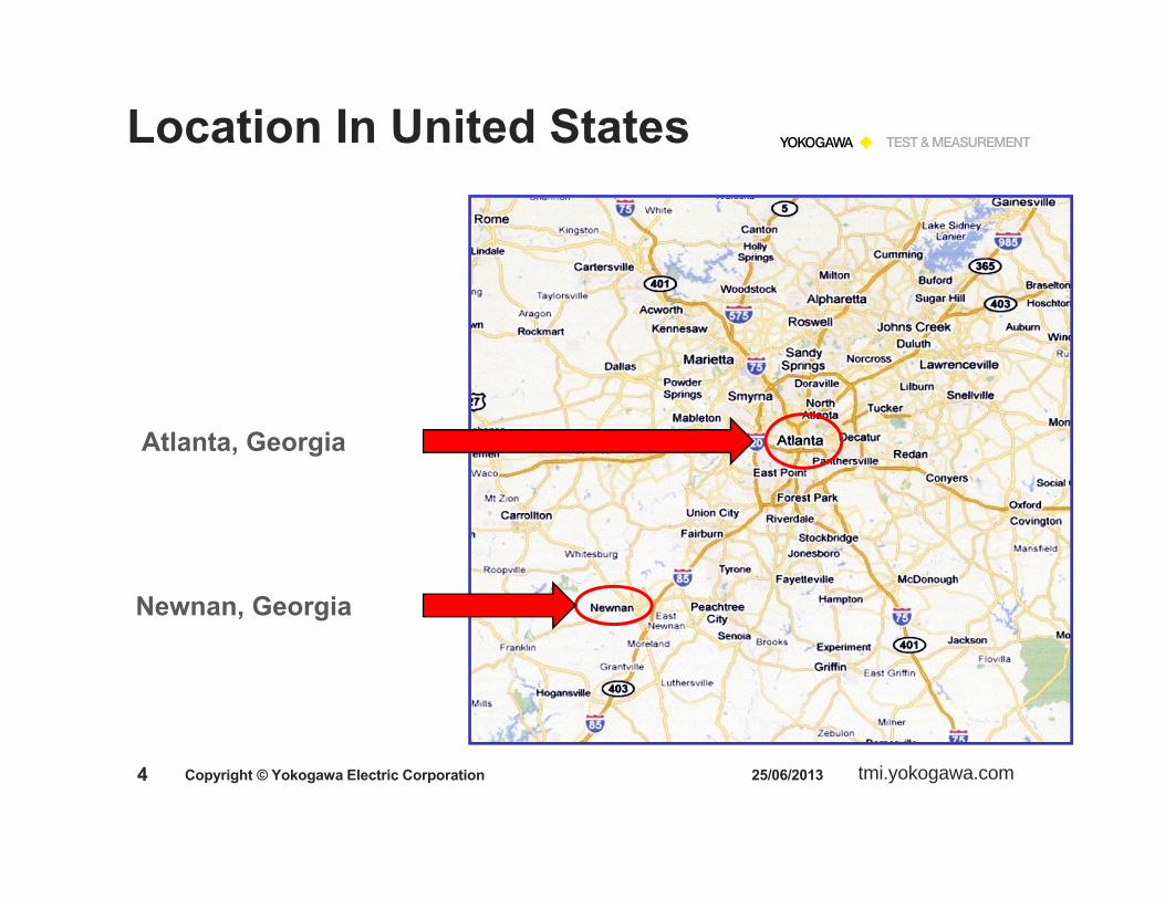
Location In United States
tmi.yokogawa.com4
Newnan, Georgia
25/06/2013Copyright © Yokogawa Electric Corporation
Location In United States
Atlanta, Georgia

tmi.yokogawa.com5
1. Electrical Power Measurement TheoryReview Some BasicsPower Measurements Using a Precision Power Analyzer
Single-Phase Power MeasurementsCurrent SensorsThree-Phase Power Measurements2 & 3 Wattmeter Method
Power Factor MeasurementHarmonic MeasurementsStandby Power, Energy Star ®, IEC Testing
2. Power Analyzer Demonstration3. Q & A and Hands-on
25/06/2013Copyright © Yokogawa Electric Corporation
Overview

tmi.yokogawa.com6
Electrical Power Measurement Theory
25/06/2013Copyright © Yokogawa Electric Corporation

tmi.yokogawa.com7 25/06/2013Copyright © Yokogawa Electric Corporation
Review Ohm’s Law

tmi.yokogawa.com8
What’s A Watt ?A unit of Power equal to one Joule of
Energy per Second
DC Source: W = V x AAC Source: W = V x A x PF
25/06/2013Copyright © Yokogawa Electric Corporation
Measurement of Power

tmi.yokogawa.com9
Active Power: Watts P = Vrms x Arms x PF
Also sometimes referred to as True Power or Real Power
Apparent Power:Volt-Amps S = Vrms x Arms
25/06/2013Copyright © Yokogawa Electric Corporation
Measurement of PowerAC Power Measurement

tmi.yokogawa.com10 25/06/2013Copyright © Yokogawa Electric Corporation
Measurement of Power
Watts P = Vrms x Arms x PF = Urms1 x Irms1 x λ1Volt-Amps S = Vrms x Arms = Urms1 x Irms1

tmi.yokogawa.com11
Digital Power Analyzers are entirely electronic and use some form of DIGITIZING TECHNIQUE to convert analog signals to digital form.Higher end analyzers use DIGITAL SIGNAL PROCESSING techniques to determine valuesDigital Power Oscilloscopes use SPECIAL FIRMWARE to make true power measurementsDigitizing instruments are somewhat RESTRICTED because it is a sampled data techniqueMany Power Analyzers and Power Scopes apply FFTalgorithms for additional power and harmonic analysis
25/06/2013Copyright © Yokogawa Electric Corporation
Measurement of Power

tmi.yokogawa.com12 25/06/2013Copyright © Yokogawa Electric Corporation
Measurement of PowerFloating and Isolated Voltage and Current inputs
Individual Analog to Digital Converters for each signal input.

tmi.yokogawa.com13 25/06/2013Copyright © Yokogawa Electric Corporation
Measurement of Power
Yokogawa Digital Power Analyzers and Digital Power Scopes use the following method to calculate power:
Pavg = 1/T 0 v(t) * I (t) dt
Using digitizing techniques, the INSTANTANEOUS VOLTAGE is multiplied by the INSTANTANEOUS CURRENT and then INTEGRATED over some time period.
T
tmi.yokogawa.com14 25/06/2013Copyright © Yokogawa Electric Corporation
Measurement of Power
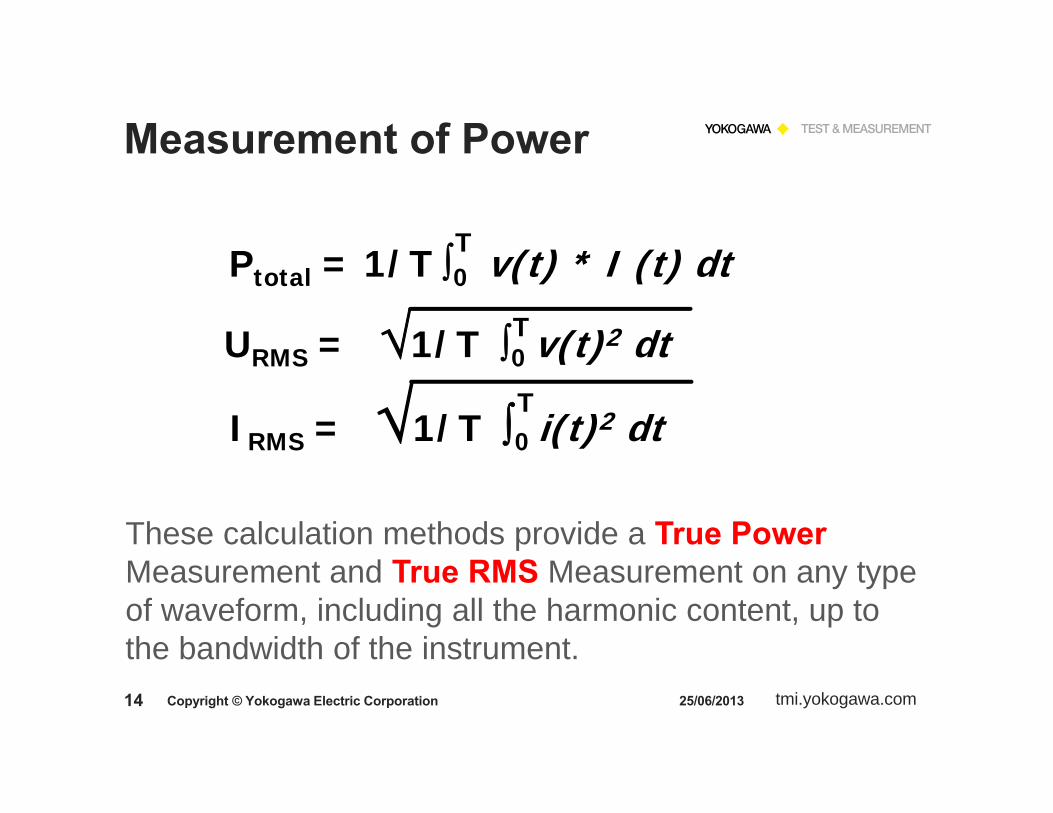
Ptotal = 1/T 0 v(t) * I (t) dt
These calculation methods provide a True Power Measurement and True RMS Measurement on any type of waveform, including all the harmonic content, up to the bandwidth of the instrument.
URMS = 1/T 0 v(t)2 dt
IRMS = 1/T 0 i(t)2 dt
T
T
T

tmi.yokogawa.com15 25/06/2013Copyright © Yokogawa Electric Corporation
Power Measurement Accuracy
Power Analyzers manufacturers often state their Power Accuracy as:
Voltage Accuracy + Current Accuracy
Accuracy of Yokogawa Power Analyzers is based on Actual Watt Measurements.
Power Accuracy is stated as:X % of Watt Reading + Y % of Watt Range

tmi.yokogawa.com16 25/06/2013Copyright © Yokogawa Electric Corporation
Measurement of PowerSingle Phase
Wattmeter
One - phasetwo - wire
LoadV(t)
I(t)
A +
V
+
ACSource
Single Wattmeter Method
Wa
tmi.yokogawa.com17 25/06/2013Copyright © Yokogawa Electric Corporation
Measurement of PowerAC Power Measurement
Single-Phase Two-Wire System
The voltage and current detected by the METERare the voltage and current applied directly to the Load.
The indication on the Meter is the POWER being dissipated by the load.
tmi.yokogawa.com18 25/06/2013Copyright © Yokogawa Electric Corporation
Measurement of Power
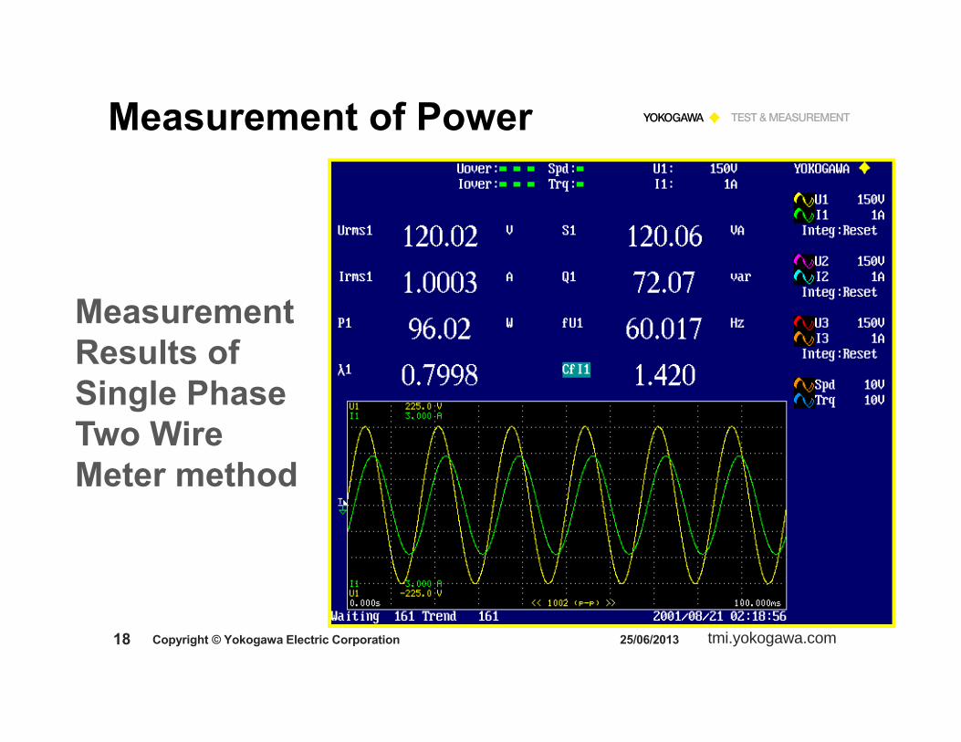
Measurement Results of Single Phase Two Wire Meter method

tmi.yokogawa.com19 25/06/2013Copyright © Yokogawa Electric Corporation
Current Sensors
Yokogawa CT’s
AEMC
Yokogawa/GMW-LEM/Danfysik CT System
Yokogawa Scope Probes
Pearson Electronics

tmi.yokogawa.com20
A WORD OF CAUTION
NEVER Open Circuit the Secondary side of a Current Transformer while it is energized!
This could cause serious damage to the CT and could possibly be harmful to equipment operators.A CT is a Current Source.By Ohm’s Law E = I x RWhen R is very large, E becomes very highThe High Voltage generated inside the CT will cause a magnetic saturation of the core, winding damage, or other damage which could destroy the CT.
25/06/2013Copyright © Yokogawa Electric Corporation
Current Sensors

tmi.yokogawa.com21 25/06/2013Copyright © Yokogawa Electric Corporation
Measurement of PowerSplit Phase
ACSource
Two Wattmeter Method
One - PhaseThree - Wire
Load
Wattmeter 1
V(t)
I(t)
V(t)
I(t)
Wattmeter 2
N
A
V
+
+
V
A +
L1
L2
PT = W1 + W2
Wa
Wb

tmi.yokogawa.com22 25/06/2013Copyright © Yokogawa Electric Corporation
Measurement of PowerAC Power Measurement
Single-Phase Three-Wire System(Split Phase)
The voltage and current detected by the METERS are the voltage and current applied directly to the Load.
The indication on EACH METER is the power being delivered by the LINE to which the meter is connected.
The total power dissipated by the load is the ALGEBRAIC SUM of the two indications.

tmi.yokogawa.com23 25/06/2013Copyright © Yokogawa Electric Corporation
Measurement of Power
Measurement Results of Single Phase Three Wire Meter method
+
tmi.yokogawa.com24 25/06/2013Copyright © Yokogawa Electric Corporation
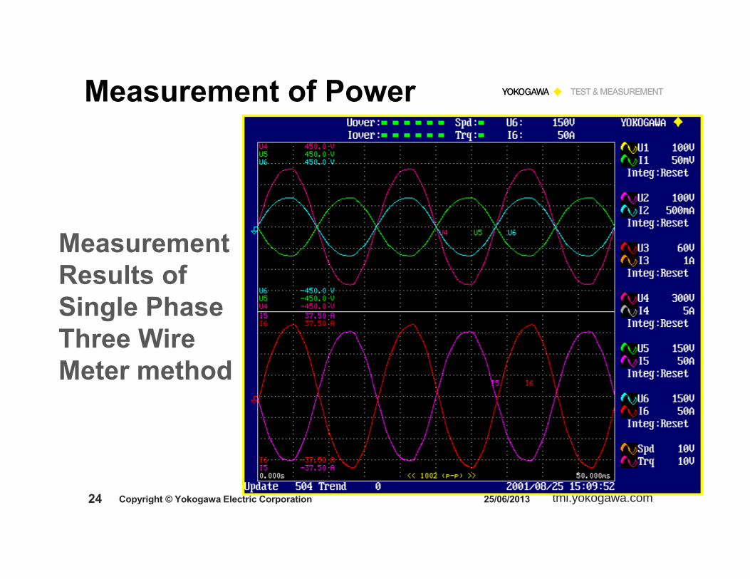
Measurement of Power
Measurement Results of Single Phase Three Wire Meter method

tmi.yokogawa.com25 25/06/2013Copyright © Yokogawa Electric Corporation
Measurement of Power
Measurement Results of Single Phase Three Wire Meter method
tmi.yokogawa.com26 25/06/2013Copyright © Yokogawa Electric Corporation
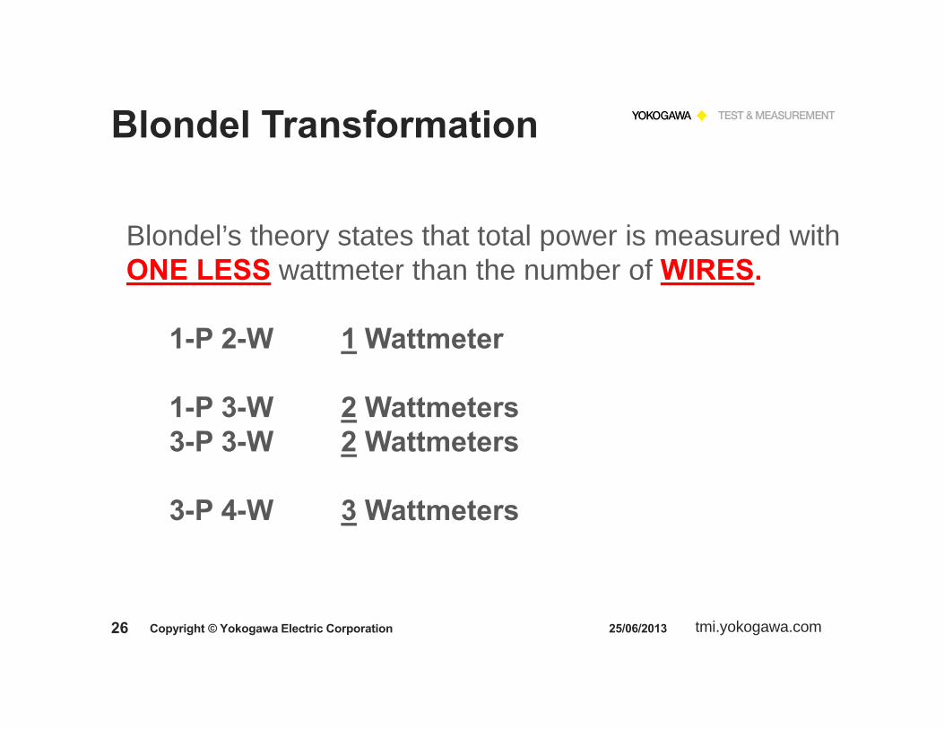
Blondel Transformation
Blondel’s theory states that total power is measured withONE LESS wattmeter than the number of WIRES.
1-P 2-W 1 Wattmeter
1-P 3-W 2 Wattmeters3-P 3-W 2 Wattmeters
3-P 4-W 3 Wattmeters

tmi.yokogawa.com27 25/06/2013Copyright © Yokogawa Electric Corporation
3-Phase 4-Wire System
van
vbn
vcn
120o
120o
120o n
vab
vbc
vca
tmi.yokogawa.com28 25/06/2013Copyright © Yokogawa Electric Corporation
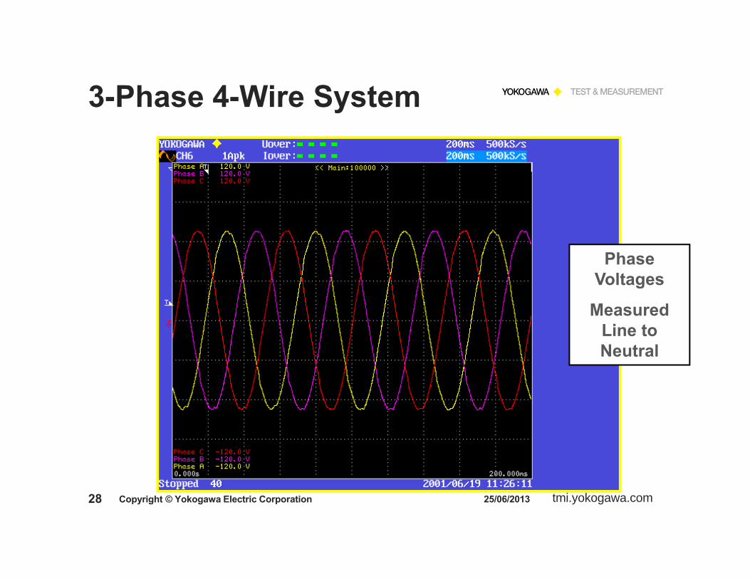
3-Phase 4-Wire System
Phase Voltages
Measured Line to Neutral
tmi.yokogawa.com29 25/06/2013Copyright © Yokogawa Electric Corporation
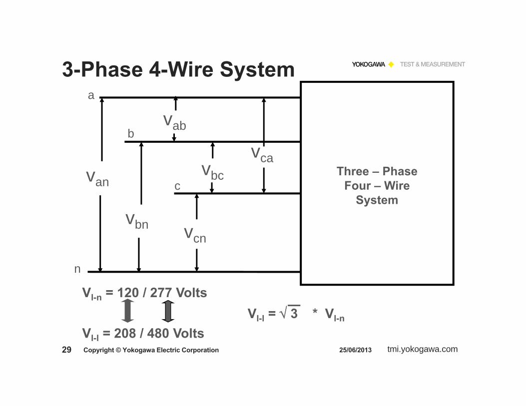
3-Phase 4-Wire Systema
b
c
n
van
vbn vcn
vab
vbc
vcaThree – Phase
Four – WireSystem
Vl-n = 120 / 277 Volts
Vl-l = 208 / 480 VoltsVl-l = 3 * Vl-n

tmi.yokogawa.com30 25/06/2013Copyright © Yokogawa Electric Corporation
3-Phase 4-Wire System
a
b
c
n
van
vbn vcn
Wa
Wb
Wc
ACSource
A
A
+
A
+
+
+
V
V
V
PT = Wa + Wb + WcThree Wattmeter
Method
Three – PhaseFour – Wire
System

tmi.yokogawa.com31 25/06/2013Copyright © Yokogawa Electric Corporation
Measurement of PowerAC Power Measurement
Three-Phase Four-Wire System
The three meters use the FOURTH wire as the common voltage REFERENCE.
Each meter indicates the PHASE power.
The TOTAL POWER for the three phases is the ALGEBRAIC SUM of the three meters.
In essence, each meter measures a SINGLE PHASE of the three phase system.

tmi.yokogawa.com32 25/06/2013Copyright © Yokogawa Electric Corporation
3-Phase 4-Wire System
+
+
+
Measurement Results of3-Phase 4-Wire System• Phase Voltage &
Current• Phase Power• Phase Power
Factor
tmi.yokogawa.com33 25/06/2013Copyright © Yokogawa Electric Corporation
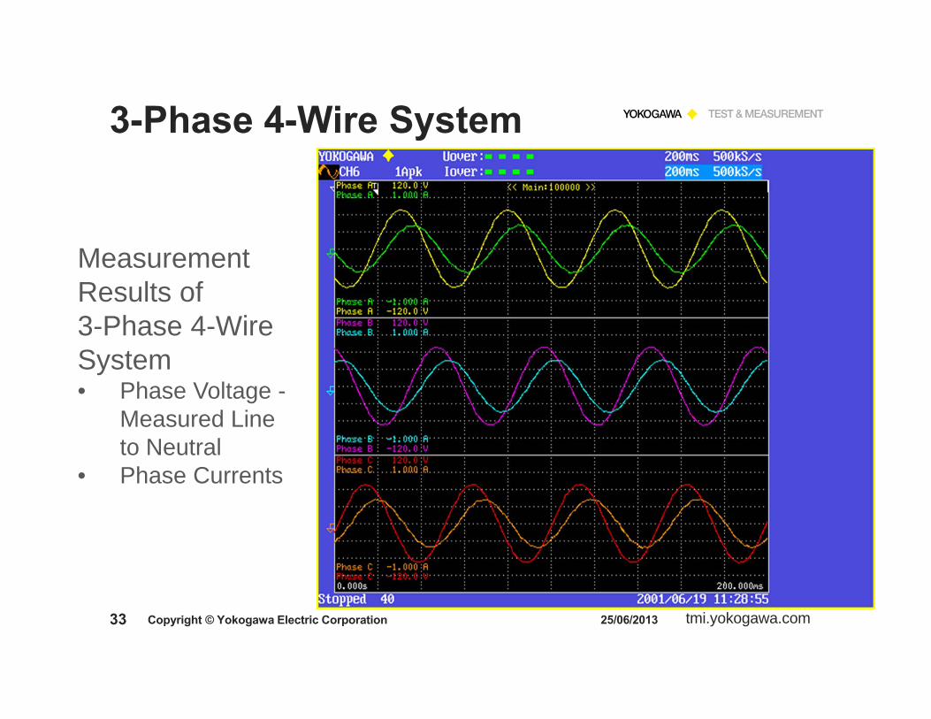
3-Phase 4-Wire System
Measurement Results of 3-Phase 4-Wire System• Phase Voltage -
Measured Line to Neutral
• Phase Currents

tmi.yokogawa.com34 25/06/2013Copyright © Yokogawa Electric Corporation
3-Phase 4-Wire System
Measurement Results of 3-Phase 4-Wire System• Phase Voltage -
Measured Line to Neutral
U1
U2U3

tmi.yokogawa.com35 25/06/2013Copyright © Yokogawa Electric Corporation
3-Phase 3-Wire System
a
b
c
vab
vcb
vca Three - Wire Three - Phase
System

tmi.yokogawa.com36 25/06/2013Copyright © Yokogawa Electric Corporation
3-Phase 3-Wire System
RememberBlondel’s Transformation
. . . total power is measured with ONE LESSwattmeter than the number of WIRES.

tmi.yokogawa.com37 25/06/2013Copyright © Yokogawa Electric Corporation
3-Phase 3-Wire System
ACSource
a
b
c
vac
vcb
vabThree - Wire Three - Phase
Load
Wa
Wb
Wc
A
A
A
V
V
+
V+
+
+
+
+
Measuring With Two Meters
PT = Wa + WbTwo Wattmeter Method
tmi.yokogawa.com38 25/06/2013Copyright © Yokogawa Electric Corporation
3-Phase 3-Wire System
The wattmeters used for this connection each measure the PHASE CURRENTS
The measured voltages are the LINE-TO-LINE values,NOT Phase Voltage.
Thus the indications on each of the meters IS NOT the power delivered by the PHASE of the measured current.
This configuration is a very NON-INTUITIVEconnection!

tmi.yokogawa.com39 25/06/2013Copyright © Yokogawa Electric Corporation
3-Phase 3-Wire System
The method yields the Total Power as the Sum of the TWO METERS in Phase 1 and 2.
Note that NONEof the meters is indicating the correct PHASE POWER.

tmi.yokogawa.com40 25/06/2013Copyright © Yokogawa Electric Corporation
Measurement of Power3-Phase 3-Wire System
The Two Wattmeter technique tends to cause less confusion than the three meter technique since there is no expectation that a meter will give an accurate phase indication.
However, with the Yokogawa Power Analyzers, on a 3-Phase 3-Wire System, use the 3V-3A wiring method. This method will give all three Voltages and Currents, and correct Total Power, Total Power Factor and VA Measurements on either Balancedor Unbalanced 3-Wire system.

tmi.yokogawa.com41 25/06/2013Copyright © Yokogawa Electric Corporation
Total P3P3W = Total P3P4W
3P-3W 3P-4W
U L-N x 3 = U L-L 55.20 x 3 = 95.60

tmi.yokogawa.com42 25/06/2013Copyright © Yokogawa Electric Corporation
Measurement of Power
All the power measurement techniques illustrated thus far have had one thing in common - - - - - - - - - - - - - - - - - - - - -The meters used to determine the total power have had a COMMON CONNECTION between them.
In the four - wire system the common point was the NEUTRAL WIRE.
In the three - wire system the common point is one of the PHASE CONNECTIONS.
The bottom line is for a THREE-WIRE system we need only TWO METERS to determine the total three - phase power.

tmi.yokogawa.com43
Power Factor Measurements
25/06/2013Copyright © Yokogawa Electric Corporation

tmi.yokogawa.com44 25/06/2013Copyright © Yokogawa Electric Corporation
Power Factor Measurements
If Power Factor is the Cosine of the Angle between Voltage and Current, then how do we measure Power Factor on a Single or Three Phase Circuit?

tmi.yokogawa.com45 25/06/2013Copyright © Yokogawa Electric Corporation
Real World Example - PF
PF = COS Ø
Where is the Zero Crossing for the Current Waveform?
How do we accurately measure Ø between these two waveforms?

tmi.yokogawa.com46 25/06/2013Copyright © Yokogawa Electric Corporation
Power Factor Measurements
For SINE WAVES ONLY
PF = Cos Ø
This is defined as the DISPLACEMENT Power Factor
---------------------------------------------------------
For All Waveforms
PF = W/VA
This is defined as TRUE Power Factor
tmi.yokogawa.com47 25/06/2013Copyright © Yokogawa Electric Corporation
Power Factor Measurements
P
QS
0
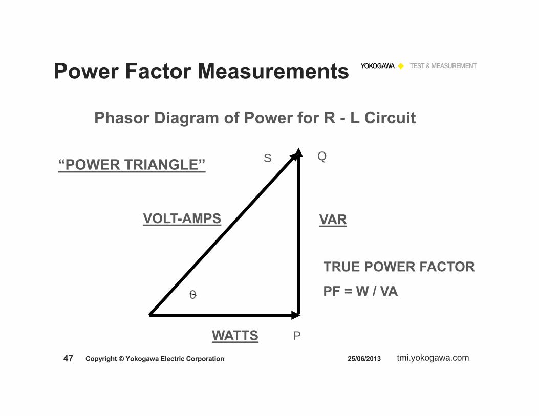
Phasor Diagram of Power for R - L Circuit
VAR
WATTS
VOLT-AMPS
TRUE POWER FACTOR
PF = W / VA
“POWER TRIANGLE”
tmi.yokogawa.com48 25/06/2013Copyright © Yokogawa Electric Corporation
Power Factor Measurements
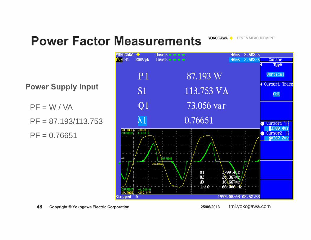
PF = W / VA
PF = 87.193/113.753
PF = 0.76651
Power Supply Input

tmi.yokogawa.com49 25/06/2013Copyright © Yokogawa Electric Corporation
Power Factor Measurements
3-Phase 4-Wire System
Using 3 wattmeter method
PFTotal = W / VA
PFTotal = ( W1 + W2 + W3 ) / ( VA1 + VA2 + VA3 )
tmi.yokogawa.com50 25/06/2013Copyright © Yokogawa Electric Corporation
Power Factor Measurements
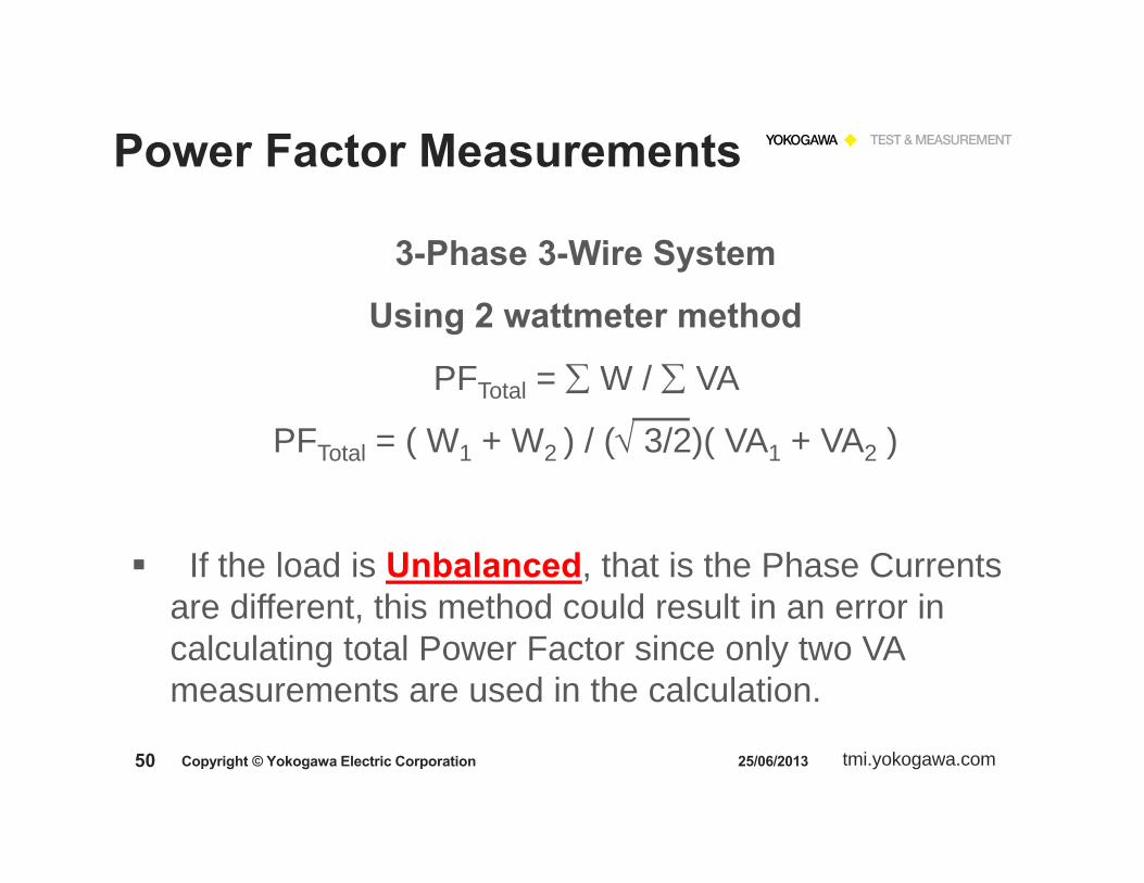
3-Phase 3-Wire System
Using 2 wattmeter method
PFTotal = W / VA
PFTotal = ( W1 + W2 ) / ( 3/2)( VA1 + VA2 )
If the load is Unbalanced, that is the Phase Currents are different, this method could result in an error in calculating total Power Factor since only two VA measurements are used in the calculation.

tmi.yokogawa.com51 25/06/2013Copyright © Yokogawa Electric Corporation
Power Factor Measurements
3-Phase 3-Wire System
Using 3 wattmeter method
PFTotal = W / VA
PFTotal = ( W1 + W2 ) / ( 3/3)( VA1 + VA2 + VA3 )
This method will give correct Power Factor calculation on either Balanced or Unbalanced 3-Wire system. Note that all three VA measurements are used in the calculation. This calculation is performed in the Yokogawa Power Analyzers when using the 3V-3A wiring method.

tmi.yokogawa.com52
Harmonic Measurements
25/06/2013Copyright © Yokogawa Electric Corporation

tmi.yokogawa.com53 25/06/2013Copyright © Yokogawa Electric Corporation
Harmonic Measurements
Why Are We Concerned with Harmonics
on the Power System?

tmi.yokogawa.com54 25/06/2013Copyright © Yokogawa Electric Corporation
Harmonics MeasurementsConcerns
Cause excess heat in electrical equipmentCause inefficient operation – wasted power, higher electric operating costsCause damage to electrical equipmentSome examples:
Transformers can be less efficientCircuit Breakers & GFI’s can tripElectric Motors can be less efficientOverheating in Neutral Conductors
tmi.yokogawa.com55 25/06/2013Copyright © Yokogawa Electric Corporation
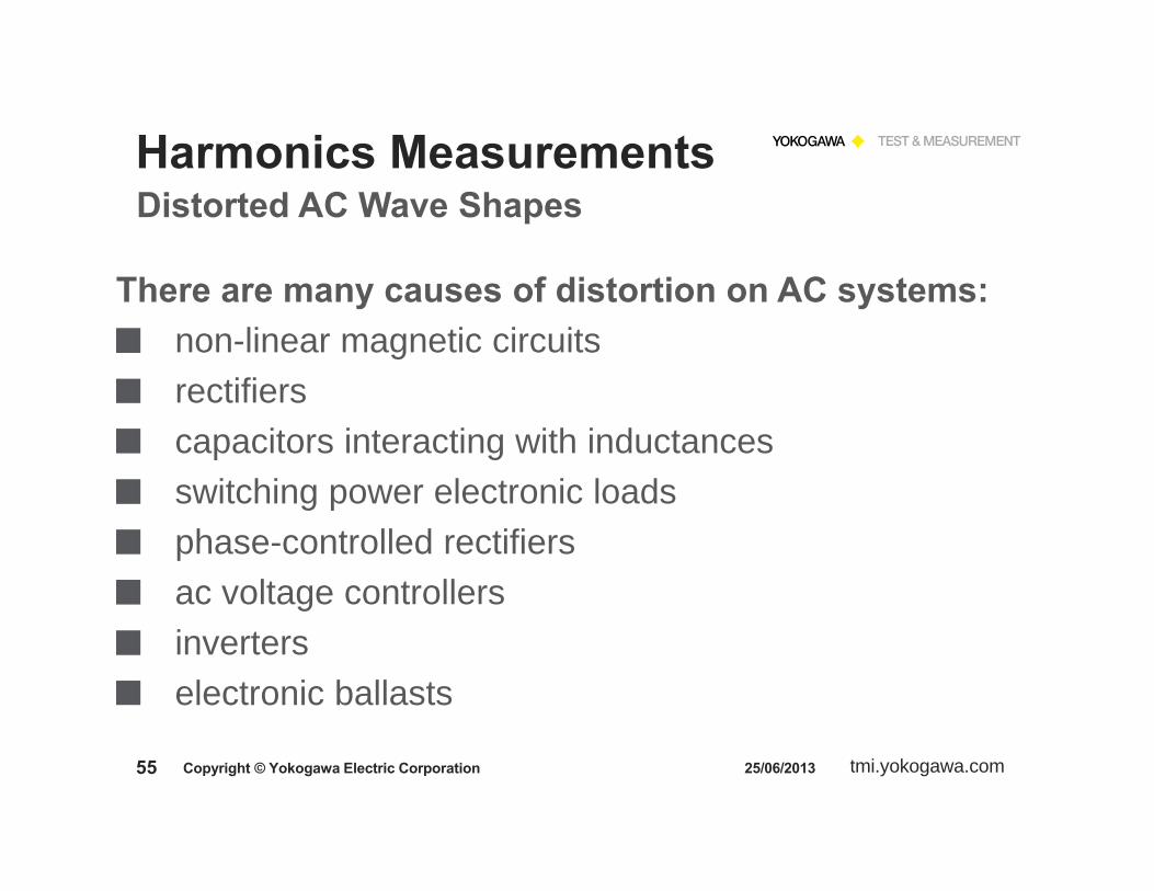
Harmonics MeasurementsDistorted AC Wave Shapes
There are many causes of distortion on AC systems:non-linear magnetic circuitsrectifierscapacitors interacting with inductancesswitching power electronic loadsphase-controlled rectifiersac voltage controllersinverterselectronic ballasts
tmi.yokogawa.com56 25/06/2013Copyright © Yokogawa Electric Corporation
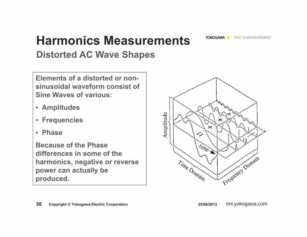
Harmonics MeasurementsDistorted AC Wave Shapes
Elements of a distorted or non-sinusoidal waveform consist of Sine Waves of various:
• Amplitudes
• Frequencies
• Phase
Because of the Phase differences in some of the harmonics, negative or reverse power can actually be produced.

tmi.yokogawa.com57 25/06/2013Copyright © Yokogawa Electric Corporation
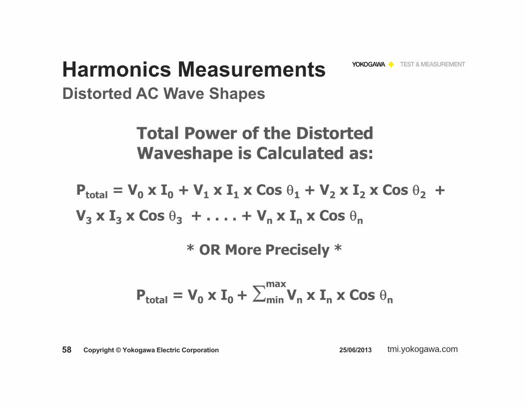
Harmonics MeasurementsDistorted AC Wave Shapes
Harmonics are usually specified as Orders180 Hz = 3rd Order for a 60 Hz Fundamental Signal(60 Hz x 3 = 180 Hz )Harmonics are also referred to as Even-order and Odd-order.In some complex waveforms, there can be Inter-Harmonics, or non-integer orders.
tmi.yokogawa.com58 25/06/2013Copyright © Yokogawa Electric Corporation
Harmonics MeasurementsDistorted AC Wave Shapes

tmi.yokogawa.com59 25/06/2013Copyright © Yokogawa Electric Corporation
Harmonics Measurements
The Yokogawa Digital Power Analyzers and Power Scopes use the FFT algorithm.
FFT Analysis must be performed on a periodic waveform with a true integer number of cycles.
Yokogawa Power Analyzers use a Phase Lock Loop (PLL) circuit to sync on the fundamental frequency and adjust the sample rate to obtain a true integer number of cycles.

tmi.yokogawa.com60 25/06/2013Copyright © Yokogawa Electric Corporation
Harmonics Measurements
Simple MATH FFT
Analysis Function

tmi.yokogawa.com61 25/06/2013Copyright © Yokogawa Electric Corporation
Harmonics Measurements
Harmonic Analysis Function
on a Power
Analyzer

tmi.yokogawa.com62 25/06/2013Copyright © Yokogawa Electric Corporation
Harmonics Measurements
Harmonic Measurement Application

tmi.yokogawa.com63 25/06/2013Copyright © Yokogawa Electric Corporation
Harmonics MeasurementsTypical
Harmonic Display
Voltage
Current
Power

tmi.yokogawa.com64 25/06/2013Copyright © Yokogawa Electric Corporation
Harmonics Measurements
Numeric Harmonic Data
DC and AC Components

tmi.yokogawa.com65 25/06/2013Copyright © Yokogawa Electric Corporation
Harmonics Measurements
Dual Data Display
Voltage Current
&
Harmonic Distortion Factor
% Total

tmi.yokogawa.com66 25/06/2013Copyright © Yokogawa Electric Corporation
Harmonics Measurements
How do we measure Harmonics in the Yokogawa Power Analyzers?
Fast Fourier Transform > FFTWhat is the PLL and what is it used for?
Yokogawa Power Analyzers use a Phase Lock Loop (PLL) circuit to sync on the fundamental frequency and adjust the sample rate to obtain a true integer number of cycles for the FFT Analysis.

tmi.yokogawa.com67
Standby PowerEnergy Star®
IEC Testing
25/06/2013Copyright © Yokogawa Electric Corporation

tmi.yokogawa.com68
What is Standby Power?Standby power is the energy consumed by appliances when they are not performing their main function. The power consumption is because of standby functions like built-in clock, memory and displays for settings and other information.
This is not to be confused with the related issue of “off mode” power, which occurs when the product is connected to the main power supply and is switched off. In this mode the equipment does not offer any functionality.
6/25/2013
Standby Power
Copyright © Yokogawa Electric Corporation
tmi.yokogawa.com69
The International Electro-technical Commission (IEC):Preparing international standards to measure and reduce standby power.
2nd edition of IEC62301 (Household electrical appliance –Measurement of standby power).
The European standard EN50564:2011 is based on IEC62301 Ed.2.0 with few modifications.
Objective: To provide a method of test to determine the power consumption of a range of appliances and equipment in Standby mode.
6/25/2013
IEC Standard
Copyright © Yokogawa Electric Corporation

tmi.yokogawa.com70
Second Edition of IEC62301 standard defines the Power Accuracy and Resolution as follows:
Power Measurement Accuracy: 1 W or greater: 2% of Reading Less than 1 W: 0.02W uncertainty
Power Measurement Resolution: 10 W or less: 0.01 W 10 to 100 W: 0.1 W Greater than 100 W: 1 W
The Measuring Instrument must have a minimum Current Range of 10 mA.
6/25/2013
IEC Standard
Copyright © Yokogawa Electric Corporation
tmi.yokogawa.com71
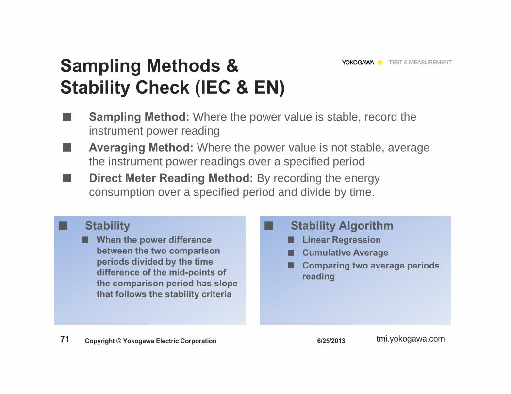
Sampling Method: Where the power value is stable, record the instrument power readingAveraging Method: Where the power value is not stable, average the instrument power readings over a specified periodDirect Meter Reading Method: By recording the energy consumption over a specified period and divide by time.
6/25/2013
Sampling Methods & Stability Check (IEC & EN)
Copyright © Yokogawa Electric Corporation
StabilityWhen the power difference between the two comparison periods divided by the time difference of the mid-points of the comparison period has slope that follows the stability criteria
Stability AlgorithmLinear RegressionCumulative AverageComparing two average periods reading

tmi.yokogawa.com72
We use the third method, Energy divided by Time > Watt-Hour/Time.
The WT Series Power Analyzers measure a True Average Power over a user selected time period.
This is the Average Active Power measurement mode.
This is the preferred method as it works on both steady and fluctuating power sources and is the most accurate method.
Yokogawa pioneered this method with the Model WT200 introduced in 2000.
6/25/2013
Yokogawa’s Standby Power Measurement
Copyright © Yokogawa Electric Corporation

tmi.yokogawa.com73 6/25/2013
Yokogawa’s Standby Power Measurement
Copyright © Yokogawa Electric Corporation
Pulse Power Mode

tmi.yokogawa.com74 6/25/2013
Yokogawa’s Solutions
Copyright © Yokogawa Electric Corporation
The World Leader in Electrical Power Measurements
tmi.yokogawa.com75
Power Analyzer Demonstration
25/06/2013Copyright © Yokogawa Electric Corporation

tmi.yokogawa.com76 25/06/2013Copyright © Yokogawa Electric Corporation
Thank YouFor
Your Time

tmi.yokogawa.com77 6/25/2013
Yokogawa Webinars On-Demand
Copyright © Yokogawa Electric Corporation
Visit our Web Sitehttps://tmi.yokogawa.com
Go toTechnical Library/Webinars On-Demand
tmi.yokogawa.com78
Yusuf ChitalwalaApplication Engineering ManagerYokogawa Corporation of AmericaTest & Measurement Division2 Dart Road, Newnan, GA 30263Tel: (800) 888-6400 Ext. 2560E-mail: [email protected]
Bill GatheridgePower Instruments Product ManagerYokogawa Corporation of AmericaTest & Measurement Division2 Dart Road, Newnan, GA 30263Tel: (800) 888-6400 Ext. 5454E-mail: [email protected]
6/25/2013
Yokogawa Contact
Copyright © Yokogawa Electric Corporation

tmi.yokogawa.com79
Q & A
25/06/2013Copyright © Yokogawa Electric Corporation


