K E Y W O R D S : f u z ~ control, autopilots, ship control, marine systems, real time control, autonomous guided vehicles
1. INTRODUCTION
The control of a sailboat consists of two main tasks: the governing of the helm and the trimming of the sails depending on the heading a n d / o r the wind angle. Historically, the first task to be automated was the governing of the helm: the autohelm. The goal was to achieve a reduction in fuel consumption, especially in high tonnage vessels such as cargo ships,
Address correspondence to Professor Oscar Caluo, L.E.L C.I., Dept. Electrotecnica, Universidad Nacional de la Plata, Calle 48 y 116, (1900) La Plata, Argentia. E-mail: calvo@athos, fisica.unlp, edu.ar.
minimizing yaws and traveled distance [1, 15, 8-10, 13]. Automatic sail trimming is a more recent idea and is still the subject of research. The goal in this case is to reach an optimum speed regime according to time and economy criteria. The main reason for the lack of research on this topic has been the disuse of sails in merchant marines since the invention of the steam engine. However, this situation is changing, mainly because of a shortage of fuels, and interest in alternative sources of energy is rising. This has brought back the sail as a very effective alternative or comple- mentary form of propulsion, as the recent use of rigid sails and turbo sails on different vessels reveals. Several studies to automatically trim the sails and optimize their efficiency are in concurrent progress.
It is known [2, 6, 11, 12] that ship dynamics is nonlinear and time-variant, depending on weather (wind, waves, and currents) and operating condi- tions (speed, load, and trimming), which are usually stochastic. If the effect of the sails is considered, the dynamics becomes still more complex. Consequently, it is extremely hard to obtain a sailboat model that includes all real conditions, to build an autopilot. However, over the centuries, man has been able to govern all kinds of vessels even under the most adverse conditions. In fact, even today, the automatic pilot is turned off by the helmsman under extreme conditions. These facts lead us to believe that fuzzy logic, an effective tool in modeling human knowledge and reasoning, could be a suitable base to develop an automatic sailboat governing system.
Motivated by all these facts, we have created an automatic control system to govern the helm and trim the sails in order to obtain an optimum speed regime. The system has been tested with an analog model, indicating the effectiveness of a fuzzy controller for this application. It also has been tested on a scale prototype, confirming the first results. In the immediate future, this sailboat will serve as an autonomous ocean sam- piing vehicle to obtain data about sea surface temperature, density, salin- ity, pollution, and wind direction and intensity.
2. GOVERNING A SAILBOAT
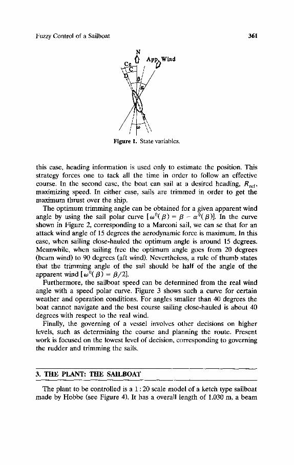
Figure 1 shows the main variables to be considered in governing a sailboat: C (course), C e (effective course), D (drift), /3 (apparent wind angle), ol (attack wind angle), ~ (rudder angle), and to (trimming angle of sails).
Basically, there are two different strategies to sail a boat: sailing close- hauled when going upwind (with a wind angle up to 70 degrees) and sailing free (with favorable wind angles). In the first case, it is mandatory to maintain a wind angle, /3 0, that allows the boat to sail at a good speed. In
Fuzzy Control of a Sailboat 361
N C ~ App~Wind
/
Figure 1. State variables.
this case, heading information is used only to estimate the position. This strategy forces one to tack all the time in order to follow an effective course. In the second case, the boat can sail at a desired heading, Rre f, maximizing speed. In either case, sails are trimmed in order to get the maximum thrust over the ship.
The optimum trimming angle can be obtained for a given apparent wind angle by using the sail polar curve [0,0(/3) = / 3 - a°(/3)]. In the curve shown in Figure 2, corresponding to a Marconi sail, we can se that for an attack wind angle of 15 degrees the aerodynamic force is maximum. In this case, when sailing close-hauled the optimum angle is around 15 degrees. Meanwhile, when sailing free the optimum angle goes from 20 degrees (beam wind) to 90 degrees (aft wind). Nevertheless, a rule of thumb states that the trimming angle of the sail should be half of the angle of the apparent wind [ ~o°(/3) =/3/2] .
Furthermore, the sailboat speed can be determined from the real wind angle with a speed polar curve. Figure 3 shows such a curve for certain weather and operation conditions. For angles smaller than 40 degrees the boat cannot navigate and the best course sailing close-hauled is about 40 degrees with respect to the real wind.
Finally, the governing of a vessel involves other decisions on higher levels, such as determining the course and planning the route. Present work is focused on the lowest level of decision, corresponding to governing the rudder and trimming the sails.
3. THE PLANT: THE SAILBOAT
The plant to be controlled is a 1 : 20 scale model of a ketch type sailboat made by Hobbe (see Figure 4). It has a overall length of 1.030 m, a beam
362 Jaime Abril et al.
/ /
/ /
& p p • W ~ n d
O' 5" I0'
4a 1 I I ~ .
-,4
• r / / / ' ~ _ / . ,"N o .'
, - , / ,b,( __ .."- \ ./ / ~ - \ ~ i - ' - _k~-
/ i
. , ,,,£.;; :: -}" \
~h Ud - Dzag Coe~iclent
Figure 2. Sail polar curve.
of 0.245 m, a total height of 1.530 m, and a displacement of 4.5 kg. Two Marconi sails on the mainmast and mizzenmast and a jib on the head stay constitute the main canvas, providing a sail area of 36.6 dm 2. A servo is used to pull all the sails. Another servo moves the rudder.
Since the sailboat exhibits rigid body motion (except for the sail), its equations of motion can be summarized by Newton's laws of conservation of linear and angular momentum. Expressing this in terms of a boat's six degrees of freedom, in matrix form, gives
U u
w
P q r
= [ mass | I L l , matrix j [ M ]
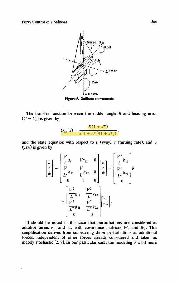
where u, v, and w are the surge, sway, and heave velocities, and p, q and r are the roll, pitch, and yaw velocities. X, Y, and Z are the components of the forces along the x, y, and z axes, and L, M, and N are the components of the moments in the same axis system. (See Figure 5.)
Fuzzy Control of a Sailboat 363
l ~ V m l
gO'
180"
Figure 3. Speed polar curve.
364 Jaime Abril et al.
Figure 4. Model sailboat.
Forces are split into separate modules representing their causes. In [6] nine different categories identified for a motor-propelled boat are consid- ered. Our model was adjusted to include the effect of the sails. Regrouping the terms, we could consider the total force as follows:
total force = hydrodynamic + aerodynamic + perturbations. The hydrodynamic term refers to the action of the water on the hull, the aerodynamic term refers to the action of the wind on the sails, and perturbations are fluctuations in wind, wave, and current forces depending on sea conditions. These forces are usually nonlinear and time-variant, but for very large ships linear approximations can be developed. Simplified linear models give reasonable accuracy, as observed in [2, 11, 12]. In this case, considering horizontal motion and neglecting coupling with vertical motion, a simple model is obtained, which is commonly used to design autopilots.
The transfer function between the rudder angle 8 and heading error (C - C e) is given by
K(1 + sT) G~'8(s) = s(1 + sT1)(1 + sT2)'
and the state equation with respect to v (sway), r (turning rate), and ~b (yaw) is given by
v ]r r ] v2 ~-all Val2 0 --~--bll V V + V 2
Z--~ a 210 ~a22 1 00 ][~bJ Z2- b21 0
+
V 2 V 2 -~-'-gl 1 --z--g12 V 2 V 2 "~g21 "~g22
0 0
Iw 2] It should be noted in this case that perturbations are considered as
additive terms w I and w 2 with covariance matrices W 1 and W 2. This simplification derives from considering those perturbations as additional forces, independent of other forces already considered and taken as merely Stochastic [2, 7]. In our particular case, the modeling is a bit more
Oscar
366 Jaime Abril et al.
~ 0
Ct
O, V~, Vb r . . . . . . . . . . .
, i
o Fuzzy : S~il~at
Controller to Dynamics b
(~....~
(a)
Grade of Membership for [3
. . . .
0 o 300 450 600 750 90o 180 o (b)
Figure 6. (a) Block diagram of the control systems. (b) Example of membership function for wind angle /3.
tedious, since the small size of the model aggravates the nonlinear and variance effects. These facts lead us to believe that obtaining a useful model for a small sailboat would be very difficult. For these reasons conventional control techniques such as PID, STR, MRAC, LQC, etc. cannot be used. Besides, the skipper's knowledge cannot be incorporate by means of conventional tools. Fuzzy logic comes to the rescue, providing an alternative way of controlling such a complex plant with reasonable results.
4. THE CONTROLLER: A FUZZY CONTROLLER
Figure 6(a) shows the proposed control scheme. The control variables are the rudder angle 8 and sail trimming angle to, and the controlled variables are the heading C and apparent wind angle /3. The fuzzy controller has been designed to compare the heading with a reference, adjusting the rudder to keep the course. The sail is trimmed to achieve maximum speed. Auxiliary rules could be added at a higher decision level to cope with different situations. Variables such as the heel angle 0, apparent wind speed Vap w and boat speed V b would be used. For example,
Fuzzy Control of a Sailboat 367
measuring the heel angle, the system could react to sudden puffs of wind slaking the sheets (an excessive heel angle reduces the effect of the rudder, lessening control over the ship). Also, measuring the apparent wind and boat speeds would help to tune the parameters of the controller for different weather conditions.
The controller chosen for this application is a Takagi-Sugeno controller [14], with rules of type
IF X 1 is A 1 AND X 2 is A 2 AND --"
THEN Z 0 = k o + k l X 1 + k 2 x 2 + . . . ,
and the output being the weighted average of all consequents:
~i wi zi z
~ i w i '
where w i is the certainty factor of the antecedent. Depending on sailing strategy, close-hauled (20 </3 < 70) or sailing free
(70 </3 < 180), different rules will be fired. For example, for small angles /3,
1F/3 is SMALL AND /3 -- f l 0 is NEGATIVE
AND A ( f l - - ~ 0) is NEGATIVE
THEN t$ = b 0 + bl(/3 - flo) + bzA( fl _ flo),
and for larger values of /3
IF/3 is LARGE AND C - C r is NEGATIVE
AND A ( C -- Cr) is NEGATIVE
THEN ~ = Po + P l ( C -- Cr) + P 2 A ( C - Cr ) ,
where/3 0 is the optimum apparent wind angle obtained from the sail polar curve, and Cr is the desired course. The presence of derivative terms A ( f l - fl0) and A ( C - C~) in the rules improves the time performance and stability of the controller. High frequency noise has been filtered.
A more complete rule base was developed and checked against simula- tions, but on searching for a minimum number of rules that still govem the boat, we found that with three basic rules that mimic the behavior of an expert sailor, the boat performed as expected. The rules are:
1. When sailing close-hauled (/3 small), not much can be done regard- ing the coursekeeping. In this case we use rule 3 below. In order to keep the course, the boat will be doing a lot of tacking, and on
368 Jaime Abril et al.
average the heading error C - C, will be small. Navigating towards a desired heading will be done by dead reckoning.
2. When sailing free, the angle /3 becomes less important, since speed improvements on changing it are small, and it is important to keep the course.
3. The trimming angle w of the sails should be half the angle of the apparent wind (/3/2); see Section 2).
Actually the system can be seen as a combination of two separate controllers: one that operates sailing close-hauled, where it is important to have good speed, tacking constantly, and a second that operates when the wind blows in the right direction, so that tacking is not necessary and controlling the wind angle is less important than the following the course. The action of each controller on the output depends on /3. A third controller could be built to perform the transition between the two controllers smoothly, or, alternatively, the decisions could all be put in a single rule base. This was the approach chosen, where each controller, reduced to its minimum expression, consists of a single rule. The rule table is filled with many don't-cares, as when the influence of some rules dominates the control action. For simplicity we do not show the complete rule base. The selection of a Takagi-Sugeno controller allowed us to reduce the rule base because the control action weights also the state variables. A Mamdani controller was used in the simulations, requiring more rules than the Takagi-Sugeno one.
In future work the knowledge base will be increased to provide smoother actions, for instance to limit the rate of change of the rudder angle. Also, with a second prototype we could have similar wind conditions for the two ships, and compare the performance of this controller with a standard PID one.
Finally, sample universes of linguistic variables /3, /3 - / 3 0, A(/3 - /30), C - C , , A ( C - Cr), 8, and to have been normalized to a [ - 1 , +1] universe (with dynamic ranges: 0 </3 < 180, 0 < C < 360, - 3 5 < ~ < 35, and 0 < to < 90). The gain factors shown in Figure 6(a), K c and K b, were set to - 1 and - 2. The coefficients for the derivatives, Kdc and Kab, were set to -0 .1 and -0.2. The linguistic variables had three term sets: negative, zero, and positive, with triangular memberships. One exception to this rule was /3, which could be small or large. An example is shown in Figure 6(b).
5. HARDWARE IMPLEMENTATION OF FUZZY CONTROLLER
The three rule controller described, measuring /3, /3 - /30 , A(/3 -- /30), C - C,, and A ( C - C,), and controlling 8 and to, was built. It was
Fuzzy Control of a Sailboat 369
implemented [3-5] using a 6270 board, developed at MIT for robot competition. The board is based on an eight bit Motorola MC68HC11A1FN microcontroller driven by a 2 MHz clock. The MC68HCll comes with an eight channel analog-to-digital converter with eight bits of resolution, serial ports, and timers with PWM capabilities. The board is equipped with a 32 Kbit of static RAM, and with LCD and keyboard interfaces. The asynchronous serial interface is used to download the software from a PC and to recover acquired data. The microprocessor is connected to different sensors such as the compass, anemometer, and vane and to actuators such as the rudder and sail-trimming servos. The system is powered by a pack of NiCd rechargeable batteries. The compass is based on a Dinsmore Hall effect unit, providing both sine and cosine voltages corresponding to the X and Y components of the terrestrial magnetic field. These values are used to compute the heading angle. A small gimbal was built to keep the compass in horizontal plane. Wind direction information is provided by a rotating vane with a small permanent magnet. The magnetic field is detected by a pair of Hall effect transistors orthogonally mounted. The wind angle is obtained in the same way as before. The anemometer is a windmill type, providing a square wave with a frequency proportional to the wind speed. This signal is generated by an optoelectronic shaft encoder sensing rotation of a system of three half cups. Provisions have been made to include devices to measure heel angle, boat speed, and absolute position (GPS). Two Futaba servos, driven by PWM signals, are used: one, of 2.5 kg, moving the rudder, and the other, of 9 kg, acting on the sails. Finally, controller actions are taken according to software running on the micro- processor, which is interrupt-driven. Interrupts are generated by a real time clock. The sample period can be changed easily. The basic operation sequence is as follows: (1) synchronization with the real time clock; (2) data reading from the compass, vane, and anemometer; (3) data filtering; (4) data processing through a fuzzy inference system; and (5) command generation for the rudder and sails. Considering the dynamics of the sailboat, a sampling period of 0.1 second proved to be sufficient. Usually, in real size vessels, autopilots operate with sampling periods from 1 to 10 seconds [1, 15, 8, 13]. When the radio control is activated, it can put the controller to work in other operating modes, such as readout, setting new courses, and programming new trajectories.
6. RESULTS
Several experiments have shown that a fuzzy controller can be used successfully to govern a sailboat. First, simulations were performed in Matlab using FISMAT (a fuzzy logic toolbox). In this case, a Takagi-Sugeno
370 Jaime Abril et al.
controller of nine rules was tested, with three fuzzy values for the input (heading), three fuzzy values for the derivative of the input (turning rate), and three singletons for the output (rudder command). The plant was a third order nonlinear one, modeling a cargo ship. Later, an analog second order model of a generic vessel was reproduced with operational amplifiers to test the system capabilities. The tests showed that a fuzzy controller was as good as the PID controller in all the dynamical tests performed. The fuzzy controller was more robust, accepting wider changes on the refer- ence signals and system parameters. Besides, to tune the PID controller, a knowledge of the plant under control was necessary, whereas in the fuzzy controller the knowledge of the expert was used to tune it. Finally, the controller was tested on the sailboat. A Takagi-Sugeno controller of two rules was used (one for sailing close-hauled and one for sailing free), with two fuzzy values for the input (wind angle: small-sailing close-hauled and large-sailing free) and proportional-derivative expressions for the output (rudder command). The selection and optimization of the membership functions and proportional-derivative coefficients was done experimentally. Three different tests were carried out: coursekeeping, in which the con- troller tries to keep a desired course acting on the rudder and on the sails according the wind angle; course tracking, in which the controller's turning ability is tested; and keeping several courses, in which the controller tries to keep different desired courses. Figure 7 shows that in coursekeeping, the controller moves the rudder between - 5 and +5 degrees with overshoots of 15 degrees to keep the course with an error smaller than 10 degrees. In Figure 8, when doing course tracking, the rudder goes violently to one extreme and then goes back to the center, testing the performance of the controller in maneuvering when going about. The turning was smooth, lasting 10 seconds, without overshoots. Finally, in keeping several courses, a small difference on the heading errors can be seen, when heading at 0 and heading at 180 with wind at 300 (Figure 9). The heading error is greater at 0, since rudder control in this situation is less aggressive. This is due to the fact that when heading at 0 (/3 < 60), the boat is controlled by the wind angle, with a gain coefficient of - 1, whereas at 180 (/3 < 120) heading control dominates, with a gain factor of - 2. When the controller was disconnected and the same boat was sailed by an expert, performance on the operations was very similar. These tests were devel- oped at the harbor of Palma de Mallorca in the Mediterranean sea with winds of force 1 and 2, sailing close-hauled and sailing free.
7. CONCLUSIONS
This paper has shown that fuzzy logic can be applied to control a complex system such as a sailboat. The knowledge of the expert, put in a
Fuzzy Control of a Sailboat 371
280 C 0 u s e l ~ (Wrd Cin ~9 Foo~ 1-~
240
16C
1,¢
0 I I I I
(a)
~ l ~ l D r . ~ 1-~
1 "2~0 40
100
I I
60 80 100 "line[s] (b)
Figure 7. Coursekeeping (wind direction 289, force 1-2): (a) heading, (b) rudder command.
372 Jaime Abril et al.
Oz~eTra~rg 0Nn~ Or. 300 Fo~e~ 2-3) 250
200
150
.~1oc 2'
-100 0
I I I | I I I
5 10 15 20 25 30 35 lirre[s] (a)
GouseTrad~rg 0Nrd Dr. 300 Fo~ 2~
40
100
8O
8O
46
I I
"1000 5 10 I I I I
15 20 25 30 35 40 ~rre[s] (b)
Figure 8. Course tracking (wind direction 300, force 2-3): (a) heading, (b) rudder command.
Fuzzy Control of a Sailboat 373
3OO
25c
23C
15c
C
-5C
-103 0
=~r'a Oouses I~l~rg 0Nn:l Dr. 300 ~ Z~
I I I I |
~n 40 6o 80 100 T.'re[s] (a)
120
Se~r~ Oouses Keepirg (Wrd Dr:. m0 Fo~ 2-,~ 1(
' ! t I o I I I 0 20 40 60 80 100 120
lirre[d (b)
Figure 9. Keeping several courses (wind direction 300, force 2-3): (a) heading, (b) rudder command.
374 Jaime Abril et al.
few rules, gave the controller similar performance to that obtained when operated by humans. Future work will include the measuring of additional state variables and the design of adaptive fuzzy controllers to tune the rules automatically for sea and weather conditions. The rule base will be enlarged to provide smoother actions and to add supervisory rules prevent- ing damage. Also, an expert system can be used to do diagnosis: the controller can be used as a teaching tool. If the boat is manually operated, rules written by an expert can explain the actions taken by the helmsman.
References
1. Abril, A. J., Sintesis comparativa de diversos controladores estocfisticos de un autotimonel ara un buque carguero, Master's Thesis, E.T.S.E.T.B.U.P.C., Barcelona, 1993.
o
2. Astr6m, K. J., and K~illstr6m, C. G., Identification of ship steering dynamics, Automatica, 12, 9-22, 1976.
o
3. Astr6m, K. J., and Wittenmark, B., Computer Controlled Systems: Theory and Design, Prentice-Hall, 1984.
4. Auslander, D. M., and Tham, C. H., Real-Time Software for Control, Prentice- Hall, 1990.
5. Bennet, S., Real-Time Computer Control: An Introduction, Prentice-HaU Inter- national (UK), 1994.
6. Browning, A. W., A mathematical model to simulate small boat behaviour, Simulation, 56, 257-264, 1991.
7. K~llstr6m, C. G., Control of yaw and roll motion by a rudder/fin- stabilization system, Proceedings of the Symposium on Ship Control Systems, Ottawa, Canada, 1981.
8. K~llstr6m, C. G., ,Astr6m, K. J., Thorell, N. E., Eriksson, J., and Sten, L., Adaptive autopilots for tankers, Automatica, 15, 241-254, 1979.
9. Layne, J. R., and Passino, K. M., Fuzzy model reference learning control for cargo ship steering, IEEE Control Systems, pp. 23-34, Dec. 1993.
10. Minorsky, N., Directional stability of automatically steered bodies, Trans. Soc. Nay. Archit. Mar. Engrs., 1922.
11. Nomoto, Taguchi, Honda, and Hirano, On the steering qualities of ships, Internat. Shipbuilding Programme 4(35), 1957.
12. Norrbin, N. H., Theory and observations on the use of a mathematical model for ship manoeuvring in deep and confined waters, Proceedings of the Sympo- sium on Naval Hydrodynamics, Pasadena, 1970.
Fuzzy Control of a Sailboat 375
13. Quevedo, J., Contribuci6n al estudio y disefio de autotimoneles para buques, PhD Thesis, Inst. de Cibern~tica-U.P.C., Barcelona, 1983.
14. Takagi, T., and Sugeno, M., Derivation of fuzzy control rules from human operator's control actions, Proceedings of the Symposium on Fuzzy Information, Knowledge Representation and Decision Analysis, Marseillles, France, 1983.
15. van Amerongen, J., Adaptive steering of ships--a model reference approach, Automatica, 20, 3-14, 1984.