104
Atlas Copco GA 18 WUX582510 Instruction book
| Date post: | 22-Oct-2015 |
| Category: |
Documents |
| Upload: | hugo-ayala |
| View: | 35 times |
| Download: | 2 times |

Atlas Copco
GA 18WUX582510
Instruction book

Atlas Copco
GA 18WUX582510
Instruction bookOriginal instructions
Manufacturing Date: 25/02/2010
Copyright noticeAny unauthorized use or copying of the contents or any part thereof is prohibited.
This applies in particular to trademarks, model denominations, part numbers and drawings.
This instruction book is valid for CE as well as non-CE labelled machines. It meets therequirements for instructions specified by the applicable European directives as identifiedin the Declaration of Conformity.
2011 - 07
www.atlascopco.com

Table of contents
1 Safety precautions..........................................................................................................6
1.1 SAFETY ICONS...................................................................................................................................6
1.2 SAFETY PRECAUTIONS, GENERAL...........................................................................................................6
1.3 SAFETY PRECAUTIONS DURING INSTALLATION...........................................................................................6
1.4 SAFETY PRECAUTIONS DURING OPERATION..............................................................................................8
1.5 SAFETY PRECAUTIONS DURING MAINTENANCE OR REPAIR...........................................................................9
2 General description......................................................................................................11
2.1 INTRODUCTION.................................................................................................................................11
2.2 AIR FLOW.......................................................................................................................................13
2.3 OIL SYSTEM....................................................................................................................................15
2.4 COOLING SYSTEM.............................................................................................................................17
2.5 CONDENSATE SYSTEM.......................................................................................................................18
2.6 REGULATING SYSTEM........................................................................................................................19
2.7 ELECTRICAL SYSTEM.........................................................................................................................20
2.8 ELECTRICAL DIAGRAMS......................................................................................................................21
2.9 AIR DRYER......................................................................................................................................23
3 Elektronikon® controller..............................................................................................24
3.1 ELEKTRONIKON® REGULATOR.............................................................................................................24
3.2 CONTROL PANEL..............................................................................................................................25
3.3 ICONS USED ON THE DISPLAY..............................................................................................................26
3.4 MAIN SCREEN..................................................................................................................................28
3.5 SHUT-DOWN WARNING.......................................................................................................................28
3.6 SHUT-DOWN....................................................................................................................................30
3.7 SERVICE WARNING............................................................................................................................31
3.8 SCROLLING THROUGH ALL SCREENS.....................................................................................................33
3.9 CALLING UP OUTLET AND DEWPOINT TEMPERATURES...............................................................................36
Instruction book
2 WUX582510
3.10 CALLING UP RUNNING HOURS..............................................................................................................37
3.11 CALLING UP MOTOR STARTS...............................................................................................................38
3.12 CALLING UP MODULE HOURS...............................................................................................................39
3.13 CALLING UP LOADING HOURS..............................................................................................................39
3.14 CALLING UP LOAD RELAY...................................................................................................................39
3.15 CALLING UP/RESETTING THE SERVICE TIMER .........................................................................................40
3.16 SELECTION BETWEEN LOCAL, REMOTE OR LAN CONTROL........................................................................41
3.17 CALLING UP/MODIFYING CAN ADDRESS CONTROL..................................................................................41
3.18 CALLING UP/MODIFYING IP, GATEWAY AND SUBNETMASK........................................................................43
3.19 CALLING UP/MODIFYING PRESSURE BAND SETTINGS.................................................................................45
3.20 MODIFYING THE PRESSURE BAND SELECTION.........................................................................................46
3.21 CALLING UP/MODIFYING SERVICE TIMER SETTINGS...................................................................................47
3.22 CALLING UP/MODIFYING THE UNIT OF TEMPERATURE................................................................................47
3.23 CALLING UP/MODIFYING UNIT OF PRESSURE...........................................................................................48
3.24 ACTIVATING AUTOMATIC RESTART AFTER VOLTAGE FAILURE......................................................................48
3.25 SELECTION BETWEEN Y-D OR DOL STARTING......................................................................................48
3.26 CALLING UP MODIFYING LOAD DELAY TIME.............................................................................................49
3.27 CALLING UP MODIFYING MINIMUM STOP TIME..........................................................................................49
3.28 ACTIVATING PASSWORD PROTECTION...................................................................................................50
3.29 ACTIVATE LOAD/UNLOAD REMOTE PRESSURE SENSING.............................................................................50
3.30 CALLING UP/MODIFYING PROTECTION SETTINGS......................................................................................51
3.31 TEST SCREENS................................................................................................................................53
3.32 WEB SERVER..................................................................................................................................54
3.33 PROGRAMMABLE SETTINGS.................................................................................................................62
4 Installation.....................................................................................................................64
4.1 DIMENSION DRAWINGS.......................................................................................................................64
4.2 INSTALLATION PROPOSAL...................................................................................................................66
4.3 ELECTRICAL CONNECTIONS.................................................................................................................68
4.4 PICTOGRAPHS.................................................................................................................................69
Instruction book
WUX582510 3

5 Operating instructions.................................................................................................70
5.1 INITIAL START-UP..............................................................................................................................70
5.2 BEFORE STARTING............................................................................................................................73
5.3 STARTING ......................................................................................................................................73
5.4 DURING OPERATION..........................................................................................................................74
5.5 CHECKING THE DISPLAY.....................................................................................................................75
5.6 STOPPING ......................................................................................................................................76
5.7 TAKING OUT OF OPERATION................................................................................................................76
6 Maintenance..................................................................................................................78
6.1 PREVENTIVE MAINTENANCE SCHEDULE..................................................................................................78
6.2 OIL SPECIFICATIONS..........................................................................................................................80
6.3 STORAGE AFTER INSTALLATION...........................................................................................................81
6.4 SERVICE KITS..................................................................................................................................81
6.5 DISPOSAL OF USED MATERIAL.............................................................................................................81
7 Adjustments and servicing procedures.....................................................................82
7.1 DRIVE MOTOR .................................................................................................................................82
7.2 AIR FILTER......................................................................................................................................82
7.3 OIL AND OIL FILTER CHANGE...............................................................................................................83
7.4 OIL SEPARATOR CHANGE...................................................................................................................84
7.5 COOLERS.......................................................................................................................................85
7.6 SAFETY VALVES...............................................................................................................................85
7.7 DRYER MAINTENANCE INSTRUCTIONS....................................................................................................86
8 Problem solving............................................................................................................88
9 Technical data...............................................................................................................91
9.1 READINGS ON DISPLAY......................................................................................................................91
9.2 ELECTRIC CABLE SIZE AND MAIN FUSES................................................................................................91
Instruction book
4 WUX582510

9.3 SETTINGS FOR MOTOR OVERLOAD RELAY..............................................................................................92
9.4 DRYER SWITCHES.............................................................................................................................93
9.5 REFERENCE CONDITIONS AND LIMITATIONS............................................................................................93
9.6 COMPRESSOR DATA FOR GA 15 UP TO GA 22....................................................................................93
9.7 TECHNICAL DATA ELEKTRONIKON® CONTROLLER....................................................................................94
10 Instructions for use......................................................................................................96
11 Guidelines for inspection.............................................................................................97
12 Pressure equipment directives...................................................................................98
13 Declaration of conformity............................................................................................99
Instruction book
WUX582510 5
1 Safety precautions
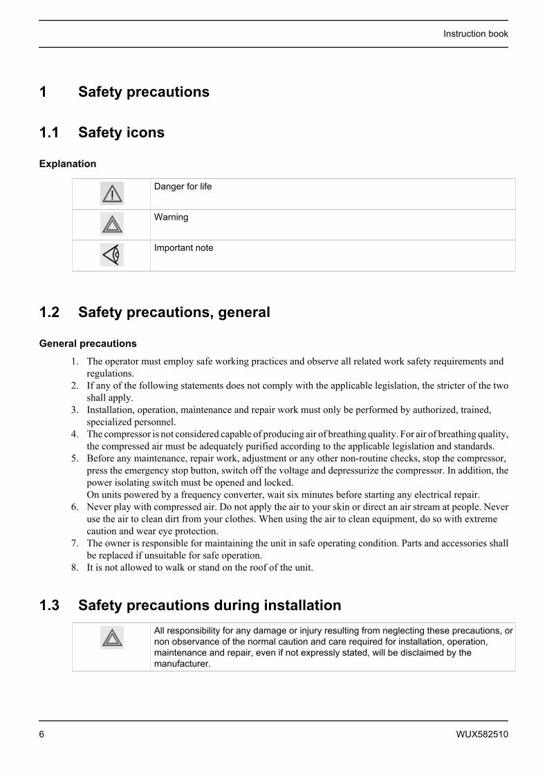
1.1 Safety icons
Explanation
Danger for life
Warning
Important note
1.2 Safety precautions, general
General precautions
1. The operator must employ safe working practices and observe all related work safety requirements andregulations.
2. If any of the following statements does not comply with the applicable legislation, the stricter of the twoshall apply.
3. Installation, operation, maintenance and repair work must only be performed by authorized, trained,specialized personnel.
4. The compressor is not considered capable of producing air of breathing quality. For air of breathing quality,the compressed air must be adequately purified according to the applicable legislation and standards.
5. Before any maintenance, repair work, adjustment or any other non-routine checks, stop the compressor,press the emergency stop button, switch off the voltage and depressurize the compressor. In addition, thepower isolating switch must be opened and locked.On units powered by a frequency converter, wait six minutes before starting any electrical repair.
6. Never play with compressed air. Do not apply the air to your skin or direct an air stream at people. Neveruse the air to clean dirt from your clothes. When using the air to clean equipment, do so with extremecaution and wear eye protection.
7. The owner is responsible for maintaining the unit in safe operating condition. Parts and accessories shallbe replaced if unsuitable for safe operation.
8. It is not allowed to walk or stand on the roof of the unit.
1.3 Safety precautions during installationAll responsibility for any damage or injury resulting from neglecting these precautions, ornon observance of the normal caution and care required for installation, operation,maintenance and repair, even if not expressly stated, will be disclaimed by themanufacturer.
Instruction book
6 WUX582510
Precautions during installation
1. The machine must only be lifted using suitable equipment in accordance with the applicable safetyregulations. Loose or pivoting parts must be securely fastened before lifting. It is strictly forbidden todwell or stay in the risk zone under a lifted load. Lifting acceleration and deceleration must be kept withinsafe limits. Wear a safety helmet when working in the area of overhead or lifting equipment.
2. The unit is designed for indoor use. If the unit is installed outdoors, special precautions must be taken;consult Atlas Copco.
3. Place the machine where the ambient air is as cool and clean as possible. If necessary, install a suctionduct. Never obstruct the air inlet. Care must be taken to minimize the entry of moisture at the inlet air.
4. Any blanking flanges, plugs, caps and desiccant bags must be removed before connecting the pipes.5. Air hoses must be of correct size and suitable for the working pressure. Never use frayed, damaged or
worn hoses. Distribution pipes and connections must be of the correct size and suitable for the workingpressure.
6. The aspirated air must be free of flammable fumes, vapours and particles, e.g. paint solvents, that can leadto internal fire or explosion.
7. Arrange the air intake so that loose clothing worn by people cannot be sucked in.8. Ensure that the discharge pipe from the compressor to the aftercooler or air net is free to expand under
heat and that it is not in contact with or close to flammable materials.9. No external force may be exerted on the air outlet valve; the connected pipe must be free of strain.10. If remote control is installed, the machine must bear a clear sign stating: DANGER: This machine is
remotely controlled and may start without warning.The operator has to make sure that the machine is stopped and that the isolating switch is open and lockedbefore any maintenance or repair. As a further safeguard, persons switching on remotely controlledmachines shall take adequate precautions to ensure that there is no one checking or working on themachine. To this end, a suitable notice shall be affixed to the start equipment.
11. Air-cooled machines must be installed in such a way that an adequate flow of cooling air is available andthat the exhausted air does not recirculate to the compressor air inlet or cooling air inlet.
12. The electrical connections must correspond to the applicable codes. The machines must be earthed andprotected against short circuits by fuses in all phases. A lockable power isolating switch must be installednear the compressor.
13. On machines with automatic start/stop system or if the automatic restart function after voltage failure isactivated, a sign stating "This machine may start without warning" must be affixed near the instrumentpanel.
14. In multiple compressor systems, manual valves must be installed to isolate each compressor. Non-returnvalves (check valves) must not be relied upon for isolating pressure systems.
15. Never remove or tamper with the safety devices, guards or insulation fitted on the machine. Every pressurevessel or auxiliary installed outside the machine to contain air above atmospheric pressure must beprotected by a pressure relieving device or devices as required.
16. Piping or other parts with a temperature in excess of 80˚C (176˚F) and which may be accidentally touchedby personnel in normal operation must be guarded or insulated. Other high temperature piping must beclearly marked.
17. For water-cooled machines, the cooling water system installed outside the machine has to be protected bya safety device with set pressure according to the maximum cooling water inlet pressure.
18. If the ground is not level or can be subject to variable inclination, consult the manufacturer.
Instruction book
WUX582510 7

Also consult following safety precautions: Safety precautions during operation and Safetyprecautions during maintenance.These precautions apply to machinery processing or consuming air or inert gas.Processing of any other gas requires additional safety precautions typical to the applicationwhich are not included herein.Some precautions are general and cover several machine types and equipment; hencesome statements may not apply to your machine.
1.4 Safety precautions during operationAll responsibility for any damage or injury resulting from neglecting these precautions, ornon observance of the normal caution and care required for installation, operation,maintenance and repair, even if not expressly stated, will be disclaimed by themanufacturer.
Precautions during operation
1. Never touch any piping or components of the compressor during operation.2. Use only the correct type and size of hose end fittings and connections. When blowing through a hose or
air line, ensure that the open end is held securely. A free end will whip and may cause injury. Make surethat a hose is fully depressurized before disconnecting it.
3. Persons switching on remotely controlled machines shall take adequate precautions to ensure that thereis no one checking or working on the machine. To this end, a suitable notice shall be affixed to the remotestart equipment.
4. Never operate the machine when there is a possibility of taking in flammable or toxic fumes, vapors orparticles.
5. Never operate the machine below or in excess of its limit ratings.6. Keep all bodywork doors shut during operation. The doors may be opened for short periods only, e.g. to
carry out routine checks. Wear ear protectors when opening a door.On compressors without bodywork, wear ear protection in the vicinity of the machine.
7. People staying in environments or rooms where the sound pressure level reaches or exceeds 80 dB(A)shall wear ear protectors.
8. Periodically check that:• All guards are in place and securely fastened• All hoses and/or pipes inside the machine are in good condition, secure and not rubbing• There are no leaks• All fasteners are tight• All electrical leads are secure and in good order• Safety valves and other pressure relief devices are not obstructed by dirt or paint• Air outlet valve and air net, i.e. pipes, couplings, manifolds, valves, hoses, etc. are in good repair, free
of wear or abuse9. If warm cooling air from compressors is used in air heating systems, e.g. to warm up a workroom, take
precautions against air pollution and possible contamination of the breathing air.10. Do not remove any of, or tamper with, the sound-damping material.11. Never remove or tamper with the safety devices, guards or insulations fitted on the machine. Every pressure
vessel or auxiliary installed outside the machine to contain air above atmospheric pressure shall beprotected by a pressure relieving device or devices as required.
Instruction book
8 WUX582510

Also consult following safety precautions: Safety precautions during installation and Safetyprecautions during maintenance.These precautions apply to machinery processing or consuming air or inert gas.Processing of any other gas requires additional safety precautions typical to the applicationwhich are not included herein.Some precautions are general and cover several machine types and equipment; hencesome statements may not apply to your machine.
1.5 Safety precautions during maintenance or repairAll responsibility for any damage or injury resulting from neglecting these precautions, ornon observance of the normal caution and care required for installation, operation,maintenance and repair, even if not expressly stated, will be disclaimed by themanufacturer.
Precautions during maintenance or repair
1. Always use the correct safety equipment (such as safety glasses, gloves, safety shoes, etc.).2. Use only the correct tools for maintenance and repair work.3. Use only genuine spare parts.4. All maintenance work shall only be undertaken when the machine has cooled down.5. A warning sign bearing a legend such as "Work in progress; do not start" shall be attached to the starting
equipment.6. Persons switching on remotely controlled machines shall take adequate precautions to ensure that there
is no one checking or working on the machine. To this end, a suitable notice shall be affixed to the remotestart equipment.
7. Close the compressor air outlet valve before connecting or disconnecting a pipe.8. Before removing any pressurized component, effectively isolate the machine from all sources of pressure
and relieve the entire system of pressure.9. Never use flammable solvents or carbon tetrachloride for cleaning parts. Take safety precautions against
toxic vapours of cleaning liquids.10. Scrupulously observe cleanliness during maintenance and repair. Keep dirt away by covering the parts
and exposed openings with a clean cloth, paper or tape.11. Never weld or perform any operation involving heat near the oil system. Oil tanks must be completely
purged, e.g. by steam cleaning, before carrying out such operations. Never weld on, or in any way modify,pressure vessels.
12. Whenever there is an indication or any suspicion that an internal part of a machine is overheated, themachine shall be stopped but no inspection covers shall be opened before sufficient cooling time haselapsed; this to avoid the risk of spontaneous ignition of the oil vapour when air is admitted.
13. Never use a light source with open flame for inspecting the interior of a machine, pressure vessel, etc.14. Make sure that no tools, loose parts or rags are left in or on the machine.15. All regulating and safety devices shall be maintained with due care to ensure that they function properly.
They may not be put out of action.16. Before clearing the machine for use after maintenance or overhaul, check that operating pressures,
temperatures and time settings are correct. Check that all control and shut-down devices are fitted and thatthey function correctly. If removed, check that the coupling guard of the compressor drive shaft has beenreinstalled.
17. Every time the separator element is renewed, examine the discharge pipe and the inside of the oil separatorvessel for carbon deposits; if excessive, the deposits should be removed.
Instruction book
WUX582510 9

18. Protect the motor, air filter, electrical and regulating components, etc. to prevent moisture from enteringthem, e.g. when steam cleaning.
19. Make sure that all sound-damping material and vibration dampers, e.g. damping material on the bodyworkand in the air inlet and outlet systems of the compressor, is in good condition. If damaged, replace it bygenuine material from the manufacturer to prevent the sound pressure level from increasing.
20. Never use caustic solvents which can damage materials of the air net, e.g. polycarbonate bowls.21. The following safety precautions are stressed when handling refrigerant:
• Never inhale refrigerant vapours. Check that the working area is adequately ventilated; if required, usebreathing protection.
• Always wear special gloves. In case of refrigerant contact with the skin, rinse the skin with water. Ifliquid refrigerant contacts the skin through clothing, never tear off or remove the latter; flushabundantly with fresh water over the clothing until all refrigerant is flushed away; then seek medicalfirst aid.
Also consult following safety precautions: Safety precautions during installation and Safetyprecautions during operation.These precautions apply to machinery processing or consuming air or inert gas.Processing of any other gas requires additional safety precautions typical to the applicationwhich are not included herein.Some precautions are general and cover several machine types and equipment; hencesome statements may not apply to your machine.
Instruction book
10 WUX582510
2 General description
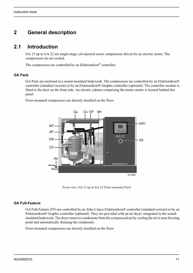
2.1 IntroductionGA 15 up to GA 22 are single-stage, oil-injected screw compressors driven by an electric motor. Thecompressors are air-cooled.
The compressors are controlled by an Elektronikon® controller.
GA Pack
GA Pack are enclosed in a sound-insulated bodywork. The compressors are controlled by an Elektronikon®controller (standard version) or by an Elektronikon® Graphic controller (optional). The controller module isfitted to the door on the front side. An electric cabinet comprising the motor starter is located behind thispanel.
Floor-mounted compressors are directly installed on the floor:
Front view, GA 15 up to GA 22 Floor-mounted Pack
GA Full-Feature
GA Full-Feature (FF) are controlled by an Atlas Copco Elektronikon® controller (standard version) or by anElektronikon® Graphic controller (optional). They are provided with an air dryer, integrated in the sound-insulated bodywork. The dryer removes condensate from the compressed air by cooling the air to near freezingpoint and automatically draining the condensate.
Floor-mounted compressors are directly installed on the floor:
Instruction book
WUX582510 11
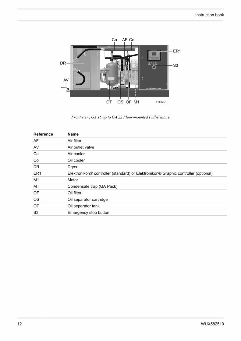
Front view, GA 15 up to GA 22 Floor-mounted Full-Feature
Reference NameAF Air filterAV Air outlet valveCa Air coolerCo Oil coolerDR DryerER1 Elektronikon® controller (standard) or Elektronikon® Graphic controller (optional)M1 MotorMT Condensate trap (GA Pack)OF Oil filterOS Oil separator cartridgeOT Oil separator tankS3 Emergency stop button
Instruction book
12 WUX582510

2.2 Air flow
Flow diagrams
Flow diagram, GA Pack
Instruction book
WUX582510 13
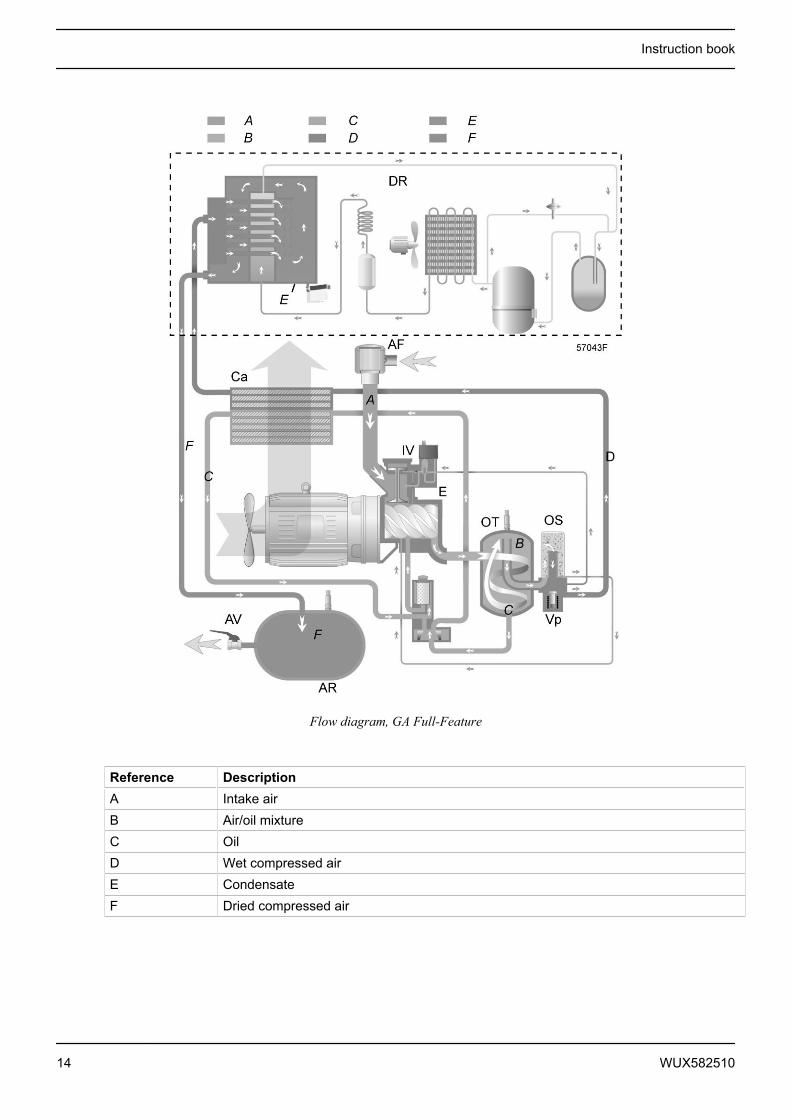
Flow diagram, GA Full-Feature
Reference DescriptionA Intake airB Air/oil mixtureC OilD Wet compressed airE CondensateF Dried compressed air
Instruction book
14 WUX582510
Description
Air drawn through filter (AF) and open inlet valve (IV) into compressor element (E) is compressed.Compressed air and oil flow into the oil tank (OT). The air is discharged through outlet valve (AV) viaminimum pressure valve (Vp) and air cooler (Ca).
During loaded operation, minimum pressure valve (Vp) keeps the pressure in the separator tank (OT) abovea minimum value, required for lubrication. An integrated check valve prevents the compressed air downstreamthe valve from being vented to atmosphere during unloaded operation.
When the compressor is stopped, inlet valve (IV) closes, preventing compressed air and oil to be vented intothe air filter.
A condensate trap (MT) downstream the air cooler is included.
On Full-Feature compressors, the air flows through air dryer (DR) before it is discharged through outlet valve(AV). Also see section Air dryer .
2.3 Oil system
Flow diagram
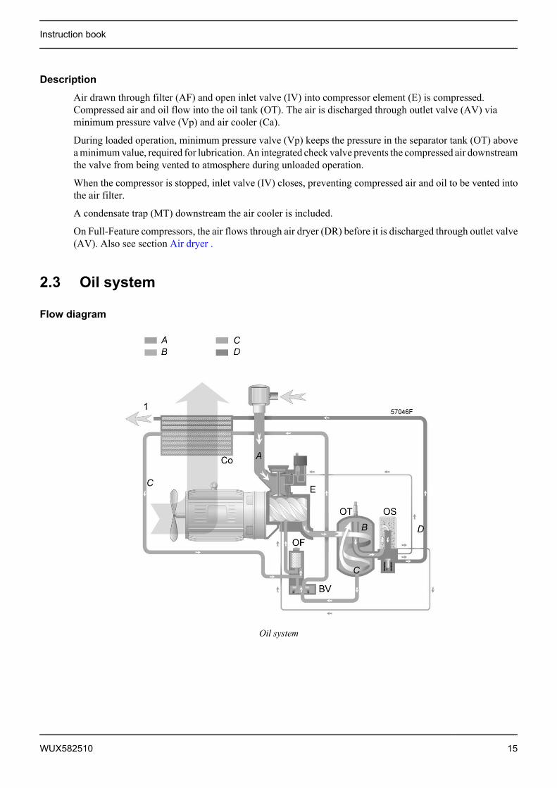
Oil system
Instruction book
WUX582510 15

References Description1 Compressed air flow towards the condensate trap (Pack units).
Compressed air flow to the air dryer (compressors with integrated dryer)A Intake airB Air/oil mixtureC OilD Wet compressed air
Description
In oil tank (OT) most of the oil is removed from the air/oil mixture by centrifugal action. The rest is removedby oil separator (OS). The oil collects in the lower part of oil tank (OT).
Air pressure forces the oil from oil tank (OT) through oil cooler (Co) and filter (OF) to compressor element(E).
The oil system is provided with a thermostatic bypass valve (BV). When the oil temperature is below its setpoint, bypass valve (BV) shuts off the supply to oil cooler (Co) and the oil cooler is bypassed.
Thermostatic bypass valve (BV) starts opening the supply from cooler (Co) when the oil temperature hasincreased to the set point. At approx. 15 ˚C (27 ˚F) above the set point, all the oil flows through the oil cooler.
Instruction book
16 WUX582510
2.4 Cooling system
Flow diagram
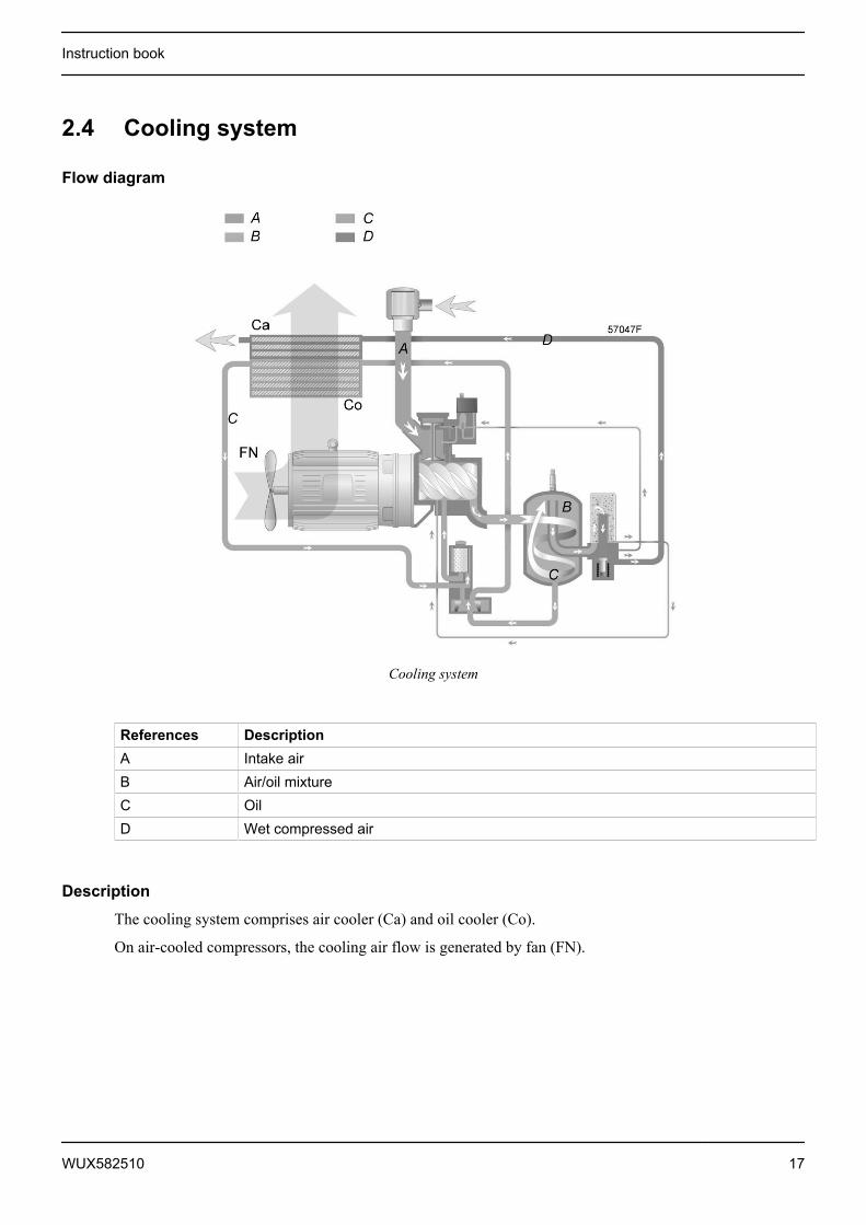
Cooling system
References DescriptionA Intake airB Air/oil mixtureC OilD Wet compressed air
Description
The cooling system comprises air cooler (Ca) and oil cooler (Co).
On air-cooled compressors, the cooling air flow is generated by fan (FN).
Instruction book
WUX582510 17

2.5 Condensate system
Condensate drains
Condensate drains, Pack units
Condensate drain, Full-Feature units
Pack units have a condensate trap (MT) downstream the air cooler. The condensate trap is provided with amanual drain outlet (Dm) and an automatic drain outlet (Da).
On Full-Feature units, the dryer is equipped with an electronic drain (1). The electronic drain is provided withan automatic drain outlet (Da).
Instruction book
18 WUX582510

2.6 Regulating system
Flow diagram
Regulating system (loaded condition)
Loading
When the net pressure is below the loading pressure, solenoid valve (Y1) is energised. Results:
• The space above unloading valve/blow-off valve (UV) is connected with the oil separator tank pressure(1) via the solenoid valve.
• Unloading valve/blow-off valve (UV) moves downwards, closing off the connection to channels (2) and(3).
• Underpressure from the compressor element causes loading plunger (LP) to move downwards and inletvalve (IV) to open fully.
Air delivery is 100%, the compressor runs loaded.
Unloading
If the air consumption is less than the air output of the compressor, the net pressure increases. When the netpressure reaches the unloading pressure, solenoid valve (Y1) is de-energised. Results:
• The pressure above unloading valve/blow-off valve (UV) is released to atmosphere and the space abovevalve (UV) is no longer in connection with the oil separator tank pressure (1).
• Unloading valve/blow-off valve (UV) moves upwards, connecting the oil separator tank pressure (1) withchannels (2) and (3).
• The pressure in channel (2) causes the loading plunger (LP) to move upwards, causing inlet valve (IV) toclose, while the pressure is gradually released to atmosphere.
• The pressure in the separator tank stabilises at low value. A small amount of air is kept drawn in toguarantee a minimal pressure, required for lubrication during unloaded operation.
Air output is stopped, the compressor runs unloaded.
Instruction book
WUX582510 19
2.7 Electrical system
General
Also consult sections Electrical diagrams and Electrical connections.
Electrical components
The electrical system comprises following components:
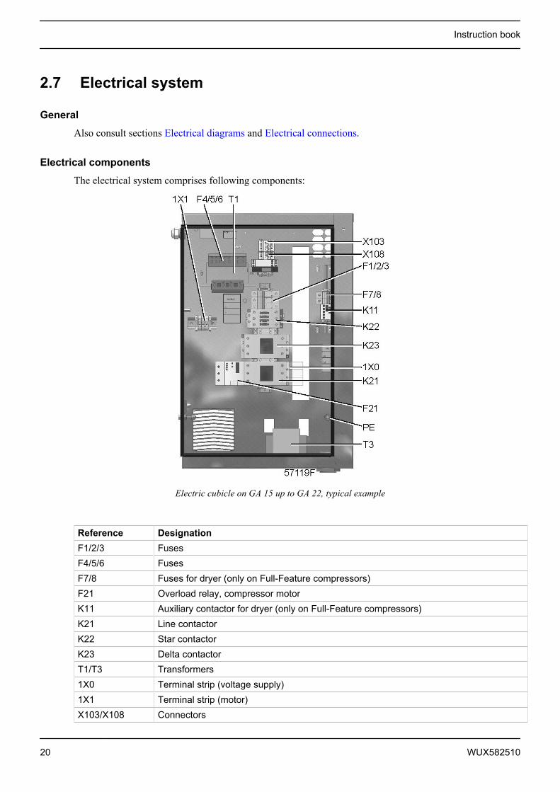
Electric cubicle on GA 15 up to GA 22, typical example
Reference DesignationF1/2/3 FusesF4/5/6 FusesF7/8 Fuses for dryer (only on Full-Feature compressors)F21 Overload relay, compressor motorK11 Auxiliary contactor for dryer (only on Full-Feature compressors)K21 Line contactorK22 Star contactorK23 Delta contactorT1/T3 Transformers1X0 Terminal strip (voltage supply)1X1 Terminal strip (motor)X103/X108 Connectors
Instruction book
20 WUX582510

Reference DesignationPE Earth terminal
2.8 Electrical diagrams
Text on drawing
Reference Designation(1) Customer’s installation(2) Option(3) All other voltages except 440-460 V - 60 Hz(4) Remote start/stop(5) Motor protection(6) Emergency stop
Instruction book
WUX582510 21
Reference Designation(7) Remote emergency stop(8) Supply of dryer(9) All other voltages
Designations used
Typical references used in the electric diagram of the compressor:
Reference CompressorA1 DryerM1 Compressor motorPT20 Pressure sensor, air deliveryTT11 Temperature sensor, element outletTT90 Temperature sensor, LAT dryer (GA Full-Feature only)Y1 Solenoid valve
Reference Starter cubicleE1 Elektronikon regulatorF1, F2,... FusesF21 Overload relay, compressor motorK11 Contactor for dryer supply (GA Full-Feature only)K21 Line contactorK22 Star contactorK23 Delta contactorS’ Remote pressure sensingS1’ Remote start/stopS3 Emergency stopS3’ Remote emergency stopT1 Transformer1X0 Power supply connection1X1 Motor connection1X3 Earth connectionX101/X108 Connectors
Reference Compressor control moduleK01 Blocking relayK02 Auxiliary relay, star contactorK03 Auxiliary relay, delta contactorK04 Auxiliary relay, load/unloadK05 Auxiliary relay, general shutdownK06 Auxiliary relay, dryerI Start
Instruction book
22 WUX582510

Reference Compressor control module0 Stop
Reference Optional equipmentB1 Electronic water drainY10 Timer drainK25 Phase sequence relayS10 Main switchR96 Anti-condensation heaters
2.9 Air dryer
Description
Air dryer
Air circuit
Compressed air enters heat exchanger (10) and is cooled by the outgoing, cold, dried air. Water in the incomingair starts to condense. The air then flows through heat exchanger/evaporator (4) where the refrigerantevaporates causing the air to be cooled further to close to the evaporating temperature of the refrigerant. Morewater in the air condenses. The cold air then flows through separator (5) where all the condensate is separatedfrom the air. The condensate is automatically drained. The cold, dried air flows through heat exchanger (10)where it is warmed up by the incoming air.
Refrigerant circuit
Compressor (1) delivers hot, high-pressure refrigerant gas which flows through condenser (2) where most ofthe refrigerant condenses.
The liquid flows through liquid refrigerant dryer/filter (8) to capillary tube (7). The refrigerant leaves thecapillary tube at evaporating pressure.
The refrigerant enters evaporator (4) where it withdraws heat from the compressed air by further evaporationat constant pressure. The heated refrigerant leaves the evaporator and is sucked in by the compressor (1).
Instruction book
WUX582510 23
3 Elektronikon® controller
3.1 Elektronikon® regulator
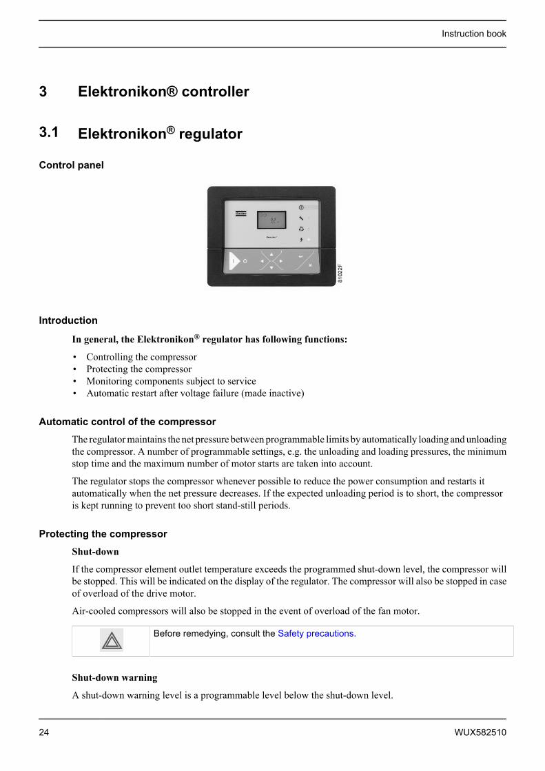
Control panel
Introduction
In general, the Elektronikon® regulator has following functions:
• Controlling the compressor• Protecting the compressor• Monitoring components subject to service• Automatic restart after voltage failure (made inactive)
Automatic control of the compressor
The regulator maintains the net pressure between programmable limits by automatically loading and unloadingthe compressor. A number of programmable settings, e.g. the unloading and loading pressures, the minimumstop time and the maximum number of motor starts are taken into account.
The regulator stops the compressor whenever possible to reduce the power consumption and restarts itautomatically when the net pressure decreases. If the expected unloading period is to short, the compressoris kept running to prevent too short stand-still periods.
Protecting the compressor
Shut-down
If the compressor element outlet temperature exceeds the programmed shut-down level, the compressor willbe stopped. This will be indicated on the display of the regulator. The compressor will also be stopped in caseof overload of the drive motor.
Air-cooled compressors will also be stopped in the event of overload of the fan motor.
Before remedying, consult the Safety precautions.
Shut-down warning
A shut-down warning level is a programmable level below the shut-down level.
Instruction book
24 WUX582510

If one of the measurements exceeds the programmed shut-down warning level, this will also be indicated towarn the operator before the shut-down level is reached.
Service warning
If the service timer exceeds a programmed value, this will be indicated on the display to warn the operator tocarry out some service actions.
Automatic restart after voltage failure
The regulator has a built-in function to automatically restart the compressor when the voltage is restored aftervoltage failure. This function is deactivated in compressors leaving the factory. If desired, the function canbe activated. Consult the Atlas Copco Customer Centre.
If activated, and if the regulator was in the automatic operation mode, the compressor willautomatically restart when the supply voltage to the module is restored!
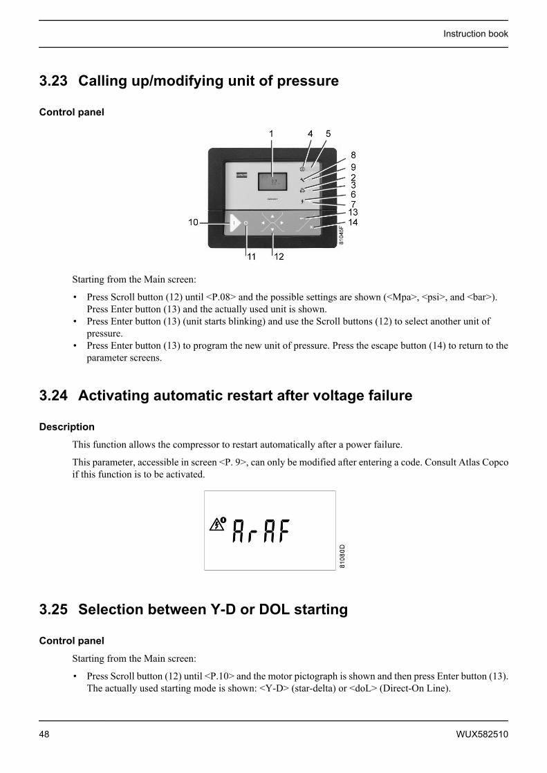
3.2 Control panel
Detailed description
Control panel of the Elektronikon controller
Reference Designation Function1 Display Shows icons and operating conditions.2 Automatic operation symbol 3 LED, Automatic operation Indicates that the regulator is automatically controlling the
compressor: the compressor is loaded, unloaded,stopped and restarted depending on the air consumptionand the limitations programmed in the regulator.
4 Warning symbol 5 LED, Warning Is lit if a warning condition exists.6 Voltage symbol 7 LED, Voltage on Indicates that the voltage is switched on.8 Service symbol
Instruction book
WUX582510 25
Reference Designation Function9 LED, Service Is lit when service is needed.10 Start button This button starts the compressor. Automatic operation
LED (3) lights up. The Elektronikon is operative.11 Stop button This button is used to stop the compressor. Automatic
operation LED (3) goes out.12 Scroll buttons Use these buttons to scroll through the menu .13 Enter button Use this button to confirm the last action.14 Escape button Use this button to go to previous screen or to end the
current action.
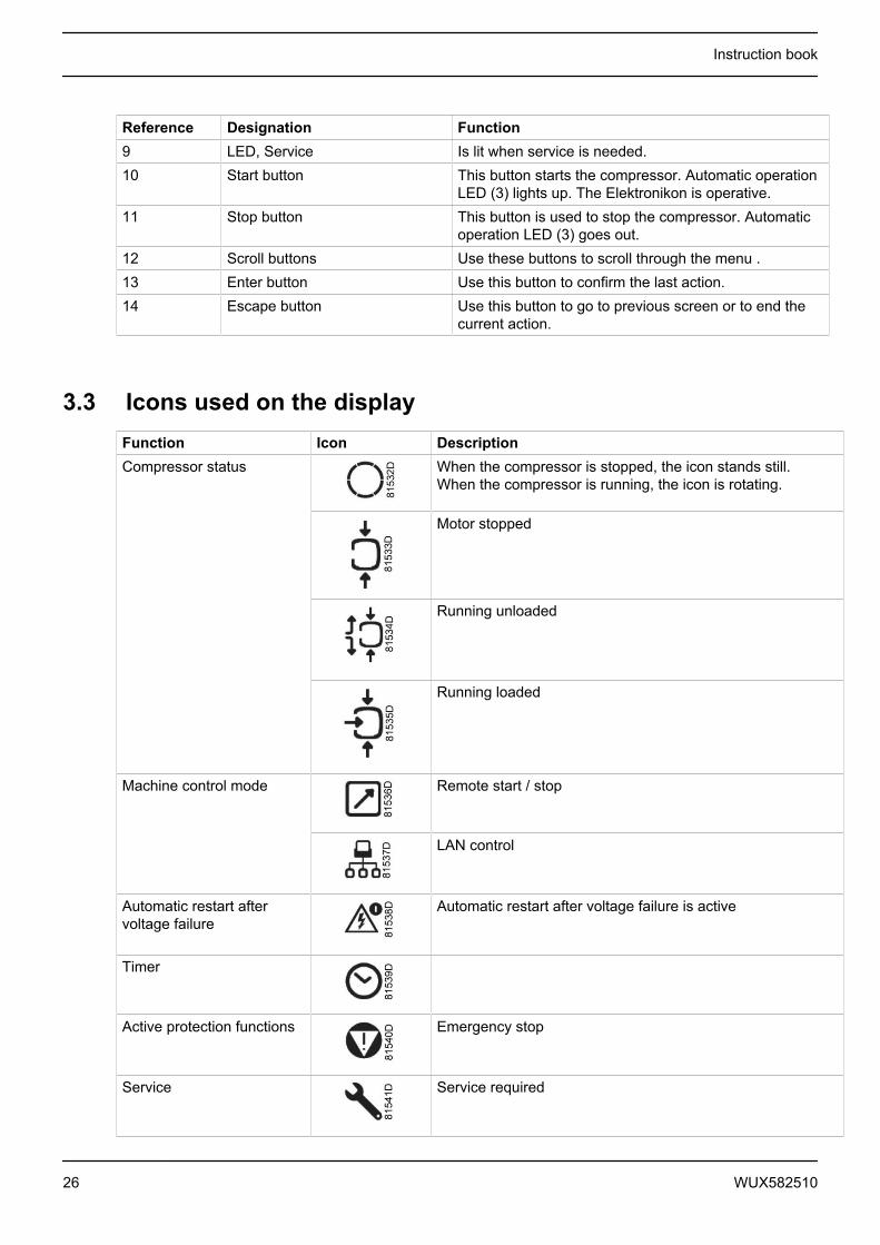
3.3 Icons used on the displayFunction Icon DescriptionCompressor status When the compressor is stopped, the icon stands still.
When the compressor is running, the icon is rotating.
Motor stopped
Running unloaded
Running loaded
Machine control mode Remote start / stop
LAN control
Automatic restart aftervoltage failure
Automatic restart after voltage failure is active
Timer
Active protection functions Emergency stop
Service Service required
Instruction book
26 WUX582510
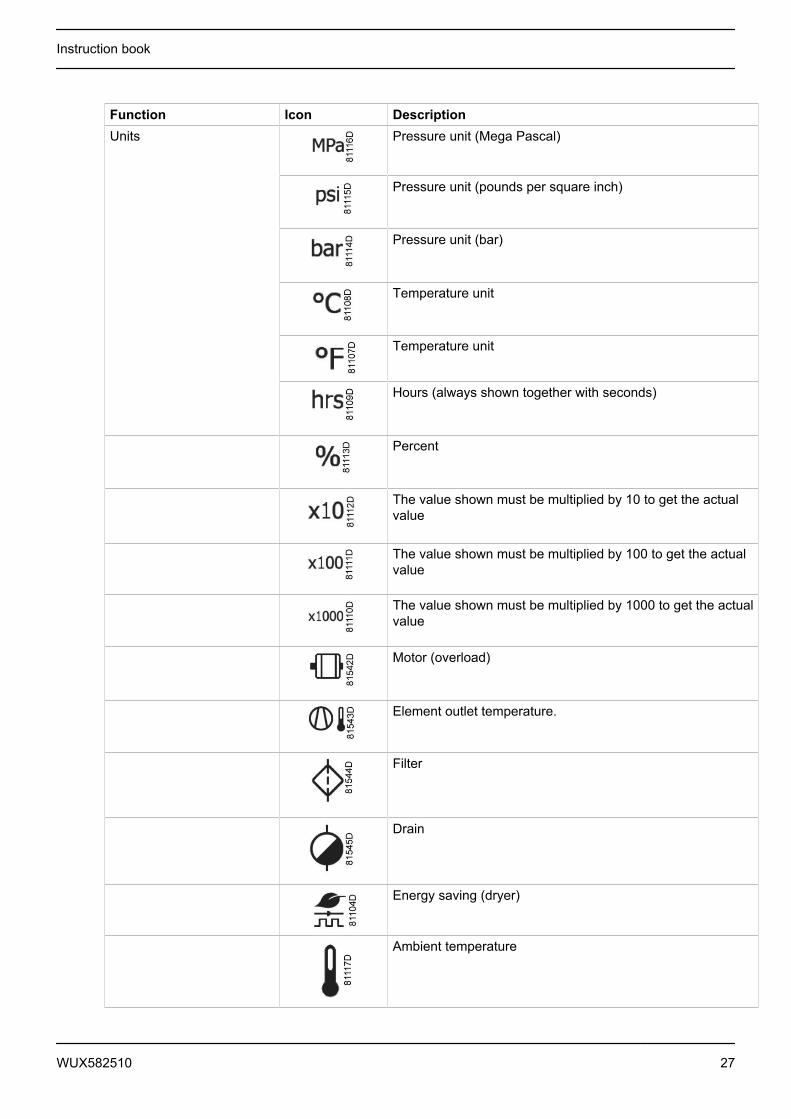
Function Icon DescriptionUnits Pressure unit (Mega Pascal)
Pressure unit (pounds per square inch)
Pressure unit (bar)
Temperature unit
Temperature unit
Hours (always shown together with seconds)
Percent
The value shown must be multiplied by 10 to get the actualvalue
The value shown must be multiplied by 100 to get the actualvalue
The value shown must be multiplied by 1000 to get the actualvalue
Motor (overload)
Element outlet temperature.
Filter
Drain
Energy saving (dryer)
Ambient temperature
Instruction book
WUX582510 27

Function Icon Description Dewpoint temperature
3.4 Main screenWhen the voltage is switched on, the first screen is a test screen. The next screen is the Main screen, shownautomatically.
The Main screen shows:
• The compressor status by means of pictographs• The air outlet pressure
Always consult Atlas Copco if the pressure on the display is preceded by a "t".
3.5 Shut-down warning
Description
A shut-down warning will appear in the event of:
• Too high a temperature at the outlet of the compressor element• Too high a dewpoint temperature (Full-Feature compressors)
Compressor element outlet temperature
• If the outlet temperature of the compressor element exceeds the shut-down warning level (see sectionProgrammable settings), warning LED (5) starts blinking.
Instruction book
28 WUX582510

• Press Scroll down button (12). The screen shows the temperature at the compressor element outlet:
The screen shows that the temperature at the element outlet is 122 °C
It remains possible to scroll through other screens, using the Scroll buttons up and down (12) to check theactual status of other parameters. Press button (11) to stop the compressor and wait until the compressor hasstopped. Switch off the voltage, inspect the compressor and remedy. The warning message will disappear assoon if the warning condition disappears.
Dewpoint temperature
On compressors with integrated dryer, alarm LED (5) will light up and the related pictograph will appearflashing if the dewpoint temperature exceeds the warning level (programmable).
Main screen with the dewpoint temperature warning
The related pictograph
will appear flashing
Press the Scroll button (12) until the actual dewpoint temperature appears.
Instruction book
WUX582510 29
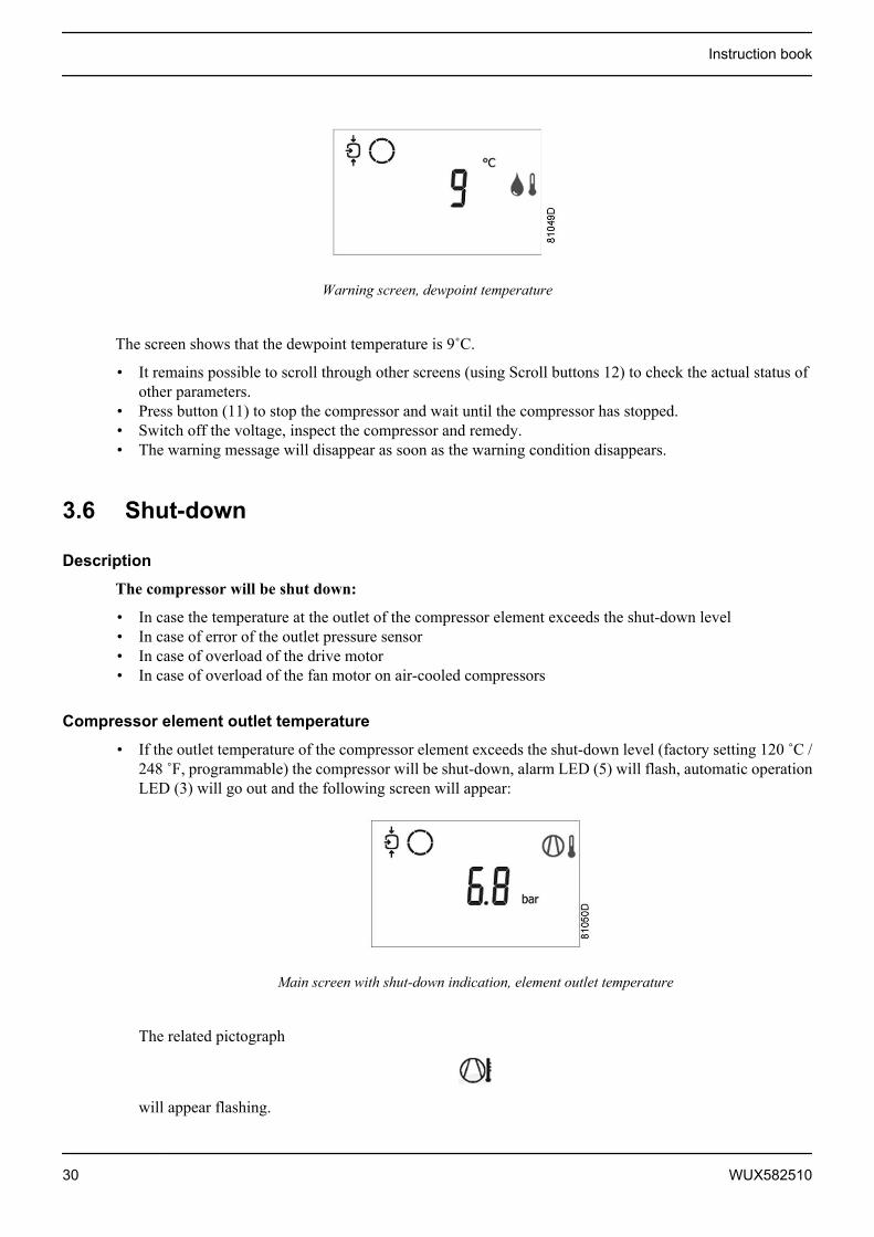
Warning screen, dewpoint temperature
The screen shows that the dewpoint temperature is 9˚C.
• It remains possible to scroll through other screens (using Scroll buttons 12) to check the actual status ofother parameters.
• Press button (11) to stop the compressor and wait until the compressor has stopped.• Switch off the voltage, inspect the compressor and remedy.• The warning message will disappear as soon as the warning condition disappears.
3.6 Shut-down
Description
The compressor will be shut down:
• In case the temperature at the outlet of the compressor element exceeds the shut-down level• In case of error of the outlet pressure sensor• In case of overload of the drive motor• In case of overload of the fan motor on air-cooled compressors
Compressor element outlet temperature
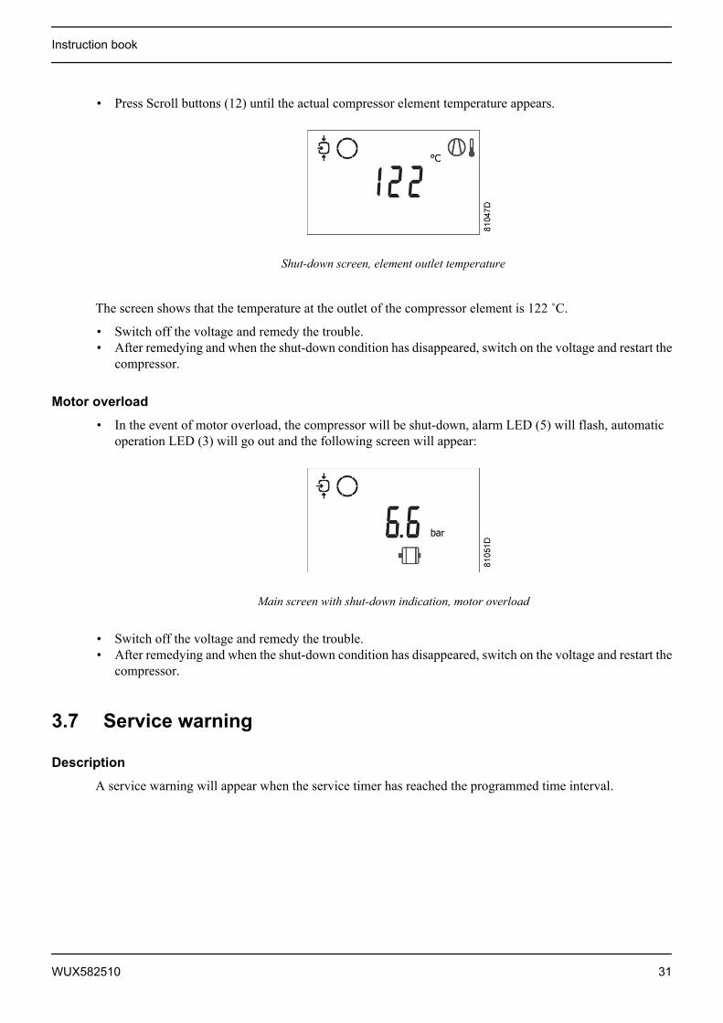
• If the outlet temperature of the compressor element exceeds the shut-down level (factory setting 120 ˚C /248 ˚F, programmable) the compressor will be shut-down, alarm LED (5) will flash, automatic operationLED (3) will go out and the following screen will appear:
Main screen with shut-down indication, element outlet temperature
The related pictograph
will appear flashing.
Instruction book
30 WUX582510
• Press Scroll buttons (12) until the actual compressor element temperature appears.
Shut-down screen, element outlet temperature
The screen shows that the temperature at the outlet of the compressor element is 122 ˚C.
• Switch off the voltage and remedy the trouble.• After remedying and when the shut-down condition has disappeared, switch on the voltage and restart the
compressor.
Motor overload
• In the event of motor overload, the compressor will be shut-down, alarm LED (5) will flash, automaticoperation LED (3) will go out and the following screen will appear:
Main screen with shut-down indication, motor overload
• Switch off the voltage and remedy the trouble.• After remedying and when the shut-down condition has disappeared, switch on the voltage and restart the
compressor.
3.7 Service warning
Description
A service warning will appear when the service timer has reached the programmed time interval.
Instruction book
WUX582510 31

• If the service timer exceeds the programmed time interval, alarm LED (5) will light up.• Press Scroll buttons (12) to scroll to <d.6> and the service symbol is shown. Press button (13): the actual
reading of the service timer appears and is shown in <hrs> or <x1000 hrs> (if the service timer value ishigher than 9999).
Example of service timer screen
The screen shows that the reading of the service timer is 4002.
• Press Scroll button (12) to scroll to <d.1> and the running hours symbol is shown. Press button (13): theactual reading of the service timer appears and is shown in <hrs> or <x1000 hrs> (if the service timervalue is higher than 9999).
Example of running hours screen
• Stop the compressor, switch off the voltage and carry out the required service actions. See sectionPreventive Maintenance.
• The longer interval service actions must also include the shorter interval actions.In the example above, carry out all service operations belonging to the 8000 runninghours interval as well as those belonging to the 4000 running hours interval.
• The setting of the service timer can be changed in function of the operating conditions.See section Preventive maintenance schedule.
Instruction book
32 WUX582510

• After servicing, reset the service timer. See section Calling up/resetting the service timer
3.8 Scrolling through all screens
Control panel
Control panel
Scroll buttons (12) can be used to scroll through all screens. The screens are divided into register screens,measured data screens, digital input screens (numbered as <d.in>, <d.1>, ...), parameter screens (numberedas <P.01>, <P.02>, ...), protections screens (numbered as <Pr.01>,...) and test screens (numbered as <t.01>,...).
During scrolling, the numbers of the screens appear consecutively. For most screens, the unit of measurementand the related pictograph are shown together with the screen number.
Example
The screen shows the screen number <d.1>, the unit used <hrs> and the related symbol for running hours.Press Enter key (13) to call up the actual running hours.
Overview of the screens
Digital inputscreens
Designation Related topic
<d.in> Digital input status <d.1> Running hours (hrs or x 1000 hrs) See section Calling-up running hours<d.2> Motor starts (x 1 or x 1000) See section Calling up motor starts<d.3> Module hours (hrs or x 1000 hrs) See section Calling up module hours
Instruction book
WUX582510 33
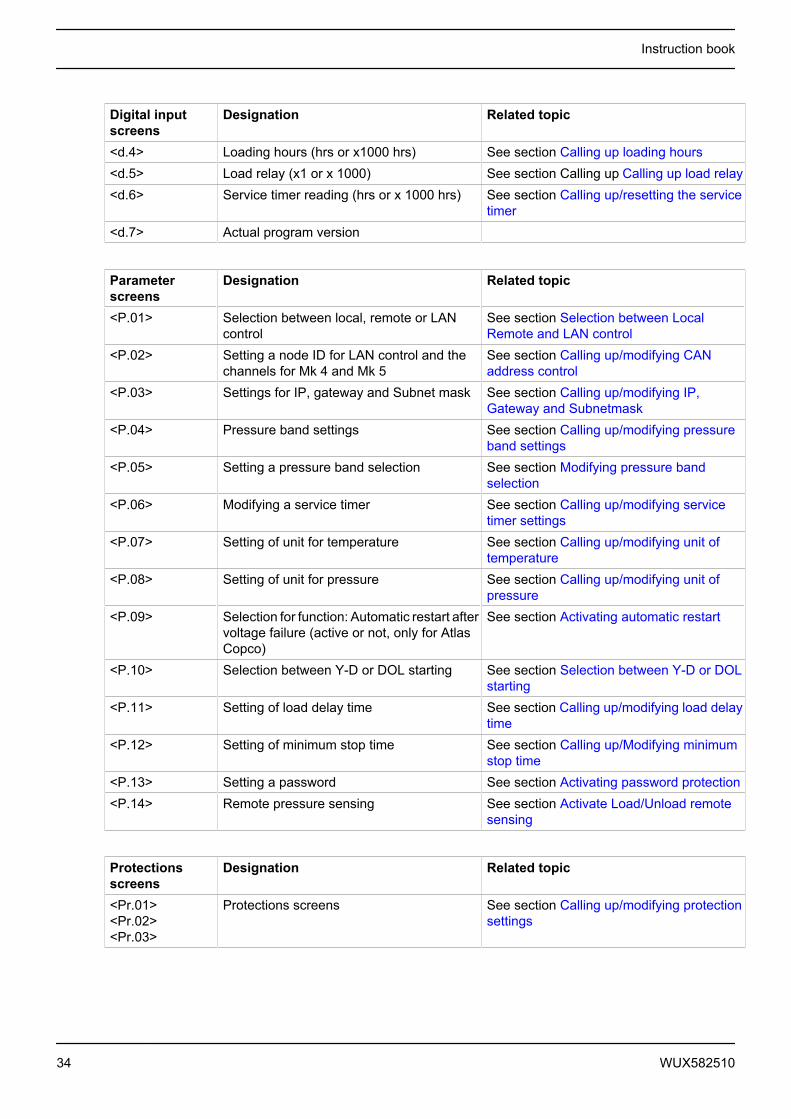
Digital inputscreens
Designation Related topic
<d.4> Loading hours (hrs or x1000 hrs) See section Calling up loading hours<d.5> Load relay (x1 or x 1000) See section Calling up Calling up load relay<d.6> Service timer reading (hrs or x 1000 hrs) See section Calling up/resetting the service
timer<d.7> Actual program version
Parameterscreens
Designation Related topic
<P.01> Selection between local, remote or LANcontrol
See section Selection between LocalRemote and LAN control
<P.02> Setting a node ID for LAN control and thechannels for Mk 4 and Mk 5
See section Calling up/modifying CANaddress control
<P.03> Settings for IP, gateway and Subnet mask See section Calling up/modifying IP,Gateway and Subnetmask
<P.04> Pressure band settings See section Calling up/modifying pressureband settings
<P.05> Setting a pressure band selection See section Modifying pressure bandselection
<P.06> Modifying a service timer See section Calling up/modifying servicetimer settings
<P.07> Setting of unit for temperature See section Calling up/modifying unit oftemperature
<P.08> Setting of unit for pressure See section Calling up/modifying unit ofpressure
<P.09> Selection for function: Automatic restart aftervoltage failure (active or not, only for AtlasCopco)
See section Activating automatic restart
<P.10> Selection between Y-D or DOL starting See section Selection between Y-D or DOLstarting
<P.11> Setting of load delay time See section Calling up/modifying load delaytime
<P.12> Setting of minimum stop time See section Calling up/Modifying minimumstop time
<P.13> Setting a password See section Activating password protection<P.14> Remote pressure sensing See section Activate Load/Unload remote
sensing
Protectionsscreens
Designation Related topic
<Pr.01><Pr.02><Pr.03>
Protections screens See section Calling up/modifying protectionsettings
Instruction book
34 WUX582510
Test screens Designation Related topic<t.01> Display test See sections Test screens<t.02> Safety valve test See sections Test screens<t.03> Production test See sections Test screens
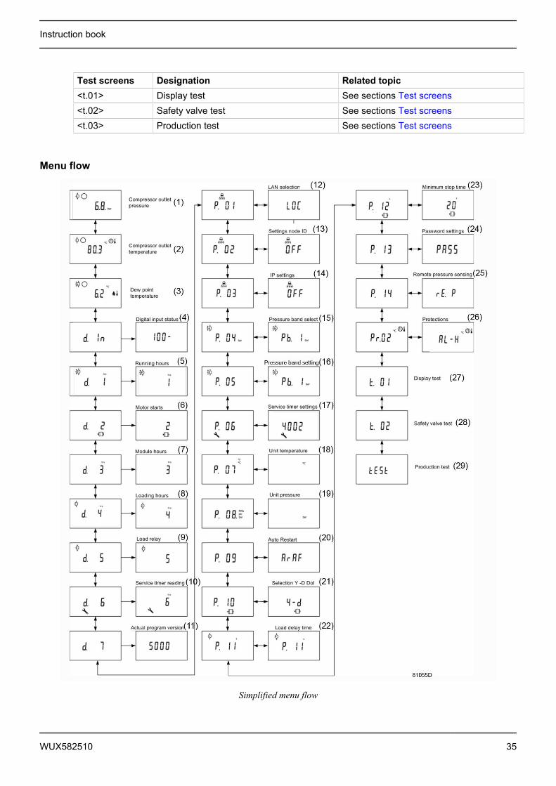
Menu flow
Simplified menu flow
Instruction book
WUX582510 35
Ref. Description Ref. Description(1) Compressor outlet pressure (16) Pressure band setting(2) Compressor outlet temperature (17) Service timer settings(3) Dewpoint temperature (18) Temperature unit(4) Digital input status (19) Unit pressure(5) Running hours (20) Auto restart(6) Motor starts (21) Selection Y-D/DOL(7) Module hours (22) Load delay time(8) Loading hours (23) Minimum stop time(9) Load relay (24) Password settings(10) Service timer reading (25) Remote pressure sensing(11) Actual program version (26) Protections(12) LAN selection (27) Display test(13) Settings node ID (28) Safety valve test(14) IP settings (29) Production test(15) Pressure band selection
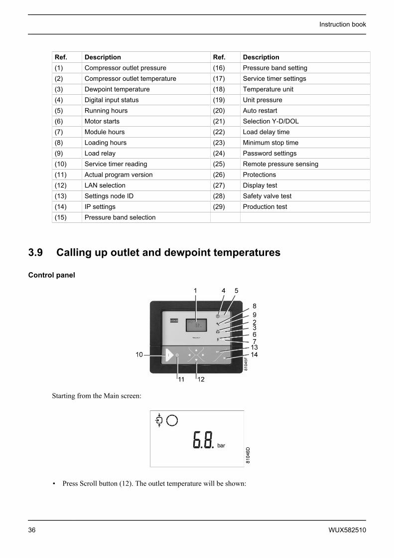
3.9 Calling up outlet and dewpoint temperatures
Control panel
Starting from the Main screen:
• Press Scroll button (12). The outlet temperature will be shown:
Instruction book
36 WUX582510

The screen shows that the outlet temperature is 82 ˚C.
• For Full-Feature compressors:Press Scroll button (12). The dewpoint temperature will be shown:
The screen shows that the dewpoint temperature is 3 ˚C.
• Press Scroll button (12) to scroll downwards or upwards through the screens.
3.10 Calling up running hours
Control panel
Starting from the Main screen:
• Press Scroll button (12) until <d.1> is shown and then press Enter button (13):
Instruction book
WUX582510 37

The screen shows the unit used (x1000 hrs) and the value (11.25): the running hours of the compressor are11250 hours.
3.11 Calling up motor starts
Control panel
Starting from the Main screen, press Scroll button (12) until <d. 2> is shown and then press Enter button (13).A screen similar to the following appears:
This screen shows the number of motor starts (x 1 or - if <x1000> lights up - x 1000). In the above example,the number of motor starts is 10100.
Instruction book
38 WUX582510

3.12 Calling up module hours
Control panel
Starting from the Main screen, press Scroll button (12) until <d. 3> is shown and then press Enter button (13).A screen similar to the following appears:
In the example shown, the screen shows the unit used (hrs) and the value (5000): the regulator module hasbeen in service during 5000 hours.
3.13 Calling up loading hoursStarting from the Main screen:
• Press Scroll button (12) until <d.4> is shown and then press Enter button (13):
The screen shows the unit used <hrs> (or <x1000 hrs>) and the value <1755>: the compressor has beenrunning loaded during 1755 hours.
3.14 Calling up load relayStarting from the Main screen:
Instruction book
WUX582510 39

• Press Scroll button (12) until <d.5> is shown and then press Enter button (13):
This screen shows the number of unload to load actions (x 1 or - if <x1000> lights up - x 1000). In the aboveexample, the number of unload to load actions is 10100.
3.15 Calling up/resetting the service timer
Calling up the service timer
Starting from the Main screen:
• Press Scroll button (12) until <d.6> is shown and then press Enter button (13):
Instruction book
40 WUX582510
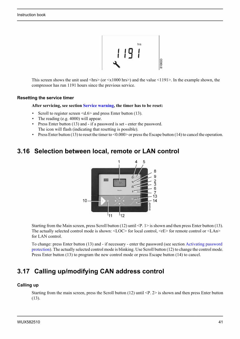
This screen shows the unit used <hrs> (or <x1000 hrs>) and the value <1191>. In the example shown, thecompressor has run 1191 hours since the previous service.
Resetting the service timer
After servicing, see section Service warning, the timer has to be reset:
• Scroll to register screen <d.6> and press Enter button (13).• The reading (e.g. 4000) will appear.• Press Enter button (13) and - if a password is set - enter the password.
The icon will flash (indicating that resetting is possible).• Press Enter button (13) to reset the timer to <0.000> or press the Escape button (14) to cancel the operation.
3.16 Selection between local, remote or LAN control
Starting from the Main screen, press Scroll button (12) until <P. 1> is shown and then press Enter button (13).The actually selected control mode is shown: <LOC> for local control, <rE> for remote control or <LAn>for LAN control.
To change: press Enter button (13) and - if necessary - enter the password (see section Activating passwordprotection). The actually selected control mode is blinking. Use Scroll button (12) to change the control mode.Press Enter button (13) to program the new control mode or press Escape button (14) to cancel.
3.17 Calling up/modifying CAN address control
Calling up
Starting from the main screen, press the Scroll button (12) until <P. 2> is shown and then press Enter button(13).
Instruction book
WUX582510 41
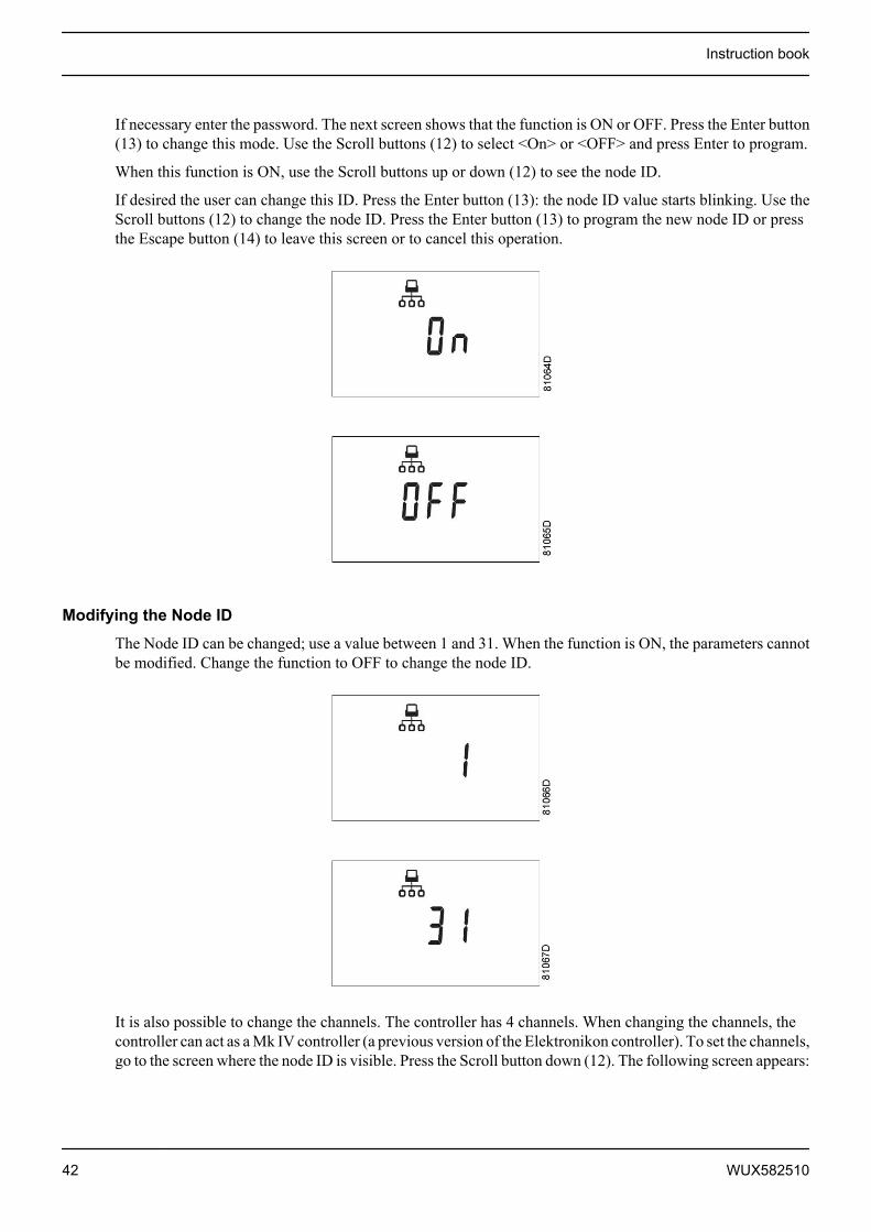
If necessary enter the password. The next screen shows that the function is ON or OFF. Press the Enter button(13) to change this mode. Use the Scroll buttons (12) to select <On> or <OFF> and press Enter to program.
When this function is ON, use the Scroll buttons up or down (12) to see the node ID.
If desired the user can change this ID. Press the Enter button (13): the node ID value starts blinking. Use theScroll buttons (12) to change the node ID. Press the Enter button (13) to program the new node ID or pressthe Escape button (14) to leave this screen or to cancel this operation.
Modifying the Node ID
The Node ID can be changed; use a value between 1 and 31. When the function is ON, the parameters cannotbe modified. Change the function to OFF to change the node ID.
It is also possible to change the channels. The controller has 4 channels. When changing the channels, thecontroller can act as a Mk IV controller (a previous version of the Elektronikon controller). To set the channels,go to the screen where the node ID is visible. Press the Scroll button down (12). The following screen appears:
Instruction book
42 WUX582510

Press the Enter button (13) to modify the setting. The utmost left value will blink. Change this value by usingthe Scroll buttons (12). Press the Enter button (13) to confirm. Change the other values in the same way, asrequired.
After modifying the settings, the screen may look as follows:
3.18 Calling up/modifying IP, Gateway and Subnetmask
Calling up
Starting from the Main screen, press the Scroll button (12) until <P. 3> is shown and then press Enter button(13).
The next screen shows either <OFF> or <On>. If <On>, press the Enter button (13) to modify it to <OFF>.Use the Scroll buttons Up or Down (12) to scroll between the items in this list (<IP> for IP address, <Sub>for Subnetmask or <GAtE> for Gateway):
Instruction book
WUX582510 43
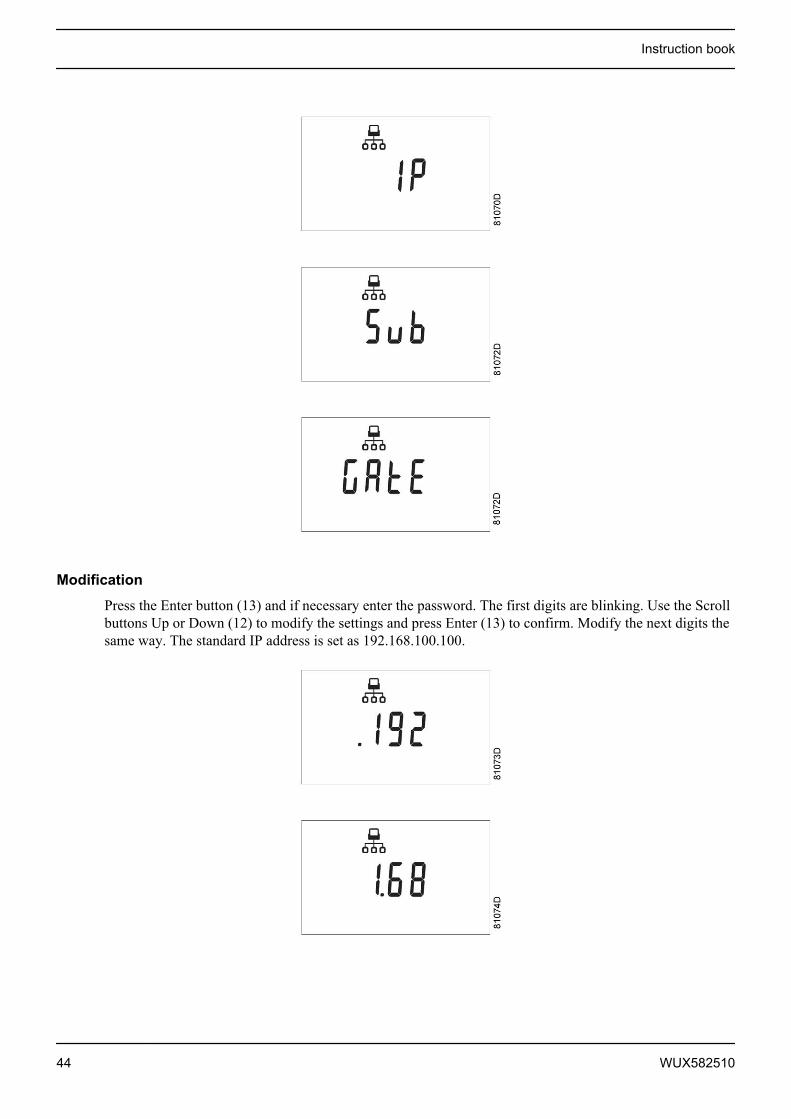
Modification
Press the Enter button (13) and if necessary enter the password. The first digits are blinking. Use the Scrollbuttons Up or Down (12) to modify the settings and press Enter (13) to confirm. Modify the next digits thesame way. The standard IP address is set as 192.168.100.100.
Instruction book
44 WUX582510
3.19 Calling up/modifying pressure band settings
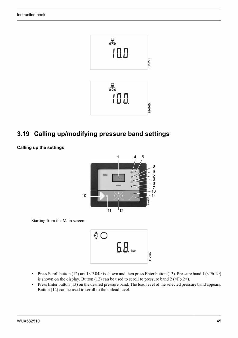
Calling up the settings
Starting from the Main screen:
• Press Scroll button (12) until <P.04> is shown and then press Enter button (13). Pressure band 1 (<Pb.1>)is shown on the display. Button (12) can be used to scroll to pressure band 2 (<Pb.2>).
• Press Enter button (13) on the desired pressure band. The load level of the selected pressure band appears.Button (12) can be used to scroll to the unload level.
Instruction book
WUX582510 45

Loading pressure
Unloading pressure
• Press Enter button (13) to modify the load level (value starts blinking). A password may be required. UseScroll buttons (12) to change the loading pressure.
• Press Enter button (13) to program the new values or press the Escape button (14) to cancel.
3.20 Modifying the pressure band selection
Control panel
Instruction book
46 WUX582510
Starting from the Main screen:
• Press Scroll button (12) until <P.05> is shown and then press Enter button (13). The active pressure band1 (<Pb.1>) is shown on the display.
• Press Enter button (13) to modify the pressure band selection (a password may be required). The activepressure band <Pb.1> starts blinking.
• Press button (12) to modify the active pressure band. Press Enter button (13) to confirm or the Escapebutton (14) to cancel.
3.21 Calling up/modifying service timer settings
Control panel
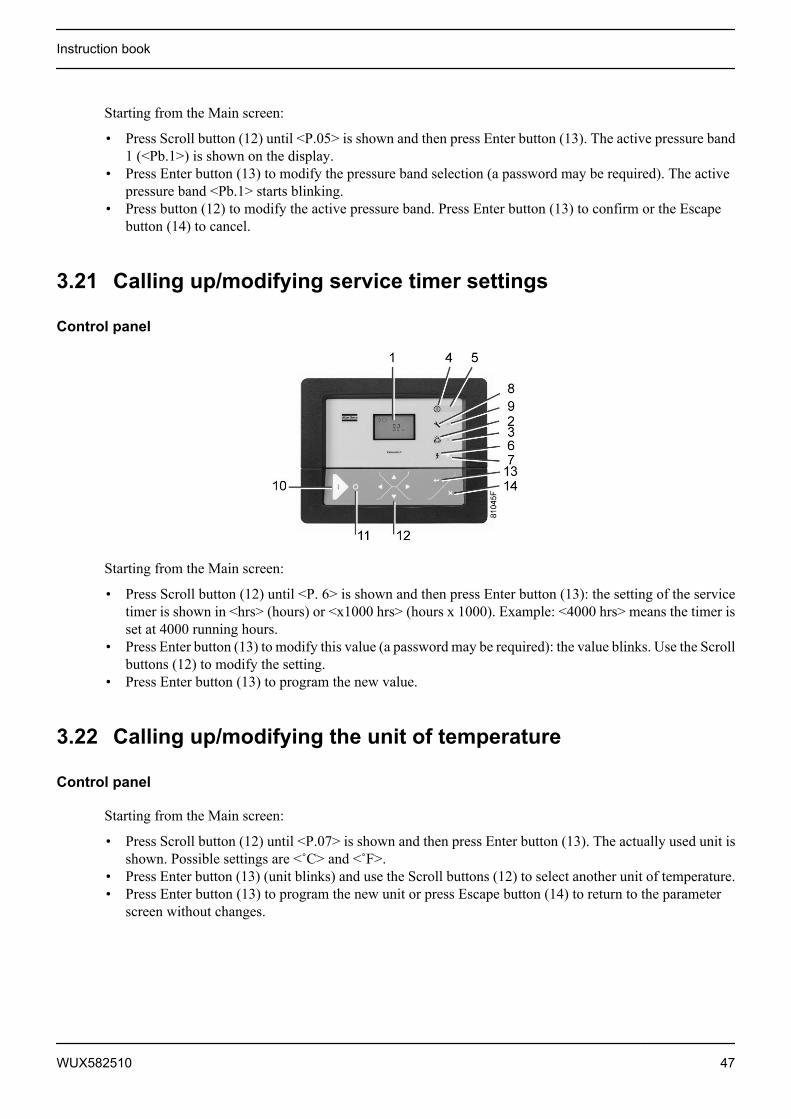
Starting from the Main screen:
• Press Scroll button (12) until <P. 6> is shown and then press Enter button (13): the setting of the servicetimer is shown in <hrs> (hours) or <x1000 hrs> (hours x 1000). Example: <4000 hrs> means the timer isset at 4000 running hours.
• Press Enter button (13) to modify this value (a password may be required): the value blinks. Use the Scrollbuttons (12) to modify the setting.
• Press Enter button (13) to program the new value.
3.22 Calling up/modifying the unit of temperature
Control panel
Starting from the Main screen:
• Press Scroll button (12) until <P.07> is shown and then press Enter button (13). The actually used unit isshown. Possible settings are <˚C> and <˚F>.
• Press Enter button (13) (unit blinks) and use the Scroll buttons (12) to select another unit of temperature.• Press Enter button (13) to program the new unit or press Escape button (14) to return to the parameter
screen without changes.
Instruction book
WUX582510 47
3.23 Calling up/modifying unit of pressure
Control panel
Starting from the Main screen:
• Press Scroll button (12) until <P.08> and the possible settings are shown (<Mpa>, <psi>, and <bar>).Press Enter button (13) and the actually used unit is shown.
• Press Enter button (13) (unit starts blinking) and use the Scroll buttons (12) to select another unit ofpressure.
• Press Enter button (13) to program the new unit of pressure. Press the escape button (14) to return to theparameter screens.
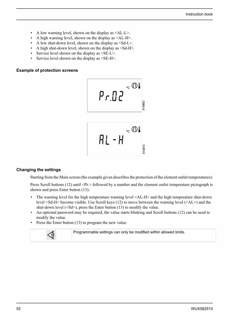
3.24 Activating automatic restart after voltage failure
Description
This function allows the compressor to restart automatically after a power failure.
This parameter, accessible in screen <P. 9>, can only be modified after entering a code. Consult Atlas Copcoif this function is to be activated.
3.25 Selection between Y-D or DOL starting
Control panel
Starting from the Main screen:
• Press Scroll button (12) until <P.10> and the motor pictograph is shown and then press Enter button (13).The actually used starting mode is shown: <Y-D> (star-delta) or <doL> (Direct-On Line).
Instruction book
48 WUX582510

• This parameter can only be modified after entering a code. Consult Atlas Copco if the parameter is to bechanged.
3.26 Calling up modifying load delay time
Control panel
Starting from the Main screen:
• Press Scroll button (12) until <P.11> and the compressor load pictograph is shown and press the Enterbutton (13):
• This screen shows the load delay time 10 and the unit <s> seconds. To modify this value press the Enterbutton (13) (a password may be required).
• The value starts blinking and Scroll buttons (12) can be used to modify the value.• Press the Enter button (13) to program the new value.
The minimum and maximum value depends on the parameters.
3.27 Calling up modifying minimum stop timeStarting from the Main screen:
Instruction book
WUX582510 49

• Press the Scroll button (12) until <P.12> and the motor pictograph is shown and press the Enter button(13):
• This screen shows the minimum stop time (20) and the unit <s> (seconds).• To modify this value press the Enter button (13). The value starts blinking and Scroll buttons (12) can be
used to modify this value.• Press Enter button (13) to program the new value.
The minimum and maximum values depend on the parameters.
3.28 Activating password protectionImportant settings such as the setting of the service timer, pressure band setting, control mode settings,... canbe protected by a password.
Starting from the Main screen:
• Press Scroll buttons (12) until <P.13> is shown and press Enter button (13):
• Password (<PASS>) appears on the screen. Press the Enter button (13).• The screen shows the password status (ON (<On>) or OFF (<OFF>). Press Enter button (13) to modify.• Change the value with Scroll buttons (12).• Select <On> and press Enter button (13).• Enter the new password and press Enter button (13) to confirm.• Enter the password again and press Enter button (13) to confirm.• <On> appears on the display. Press reset key to return to the parameter screen.
Lost passwords can not be recovered. Save the password carefully.
3.29 Activate load/unload remote pressure sensingStarting from the Main screen:
• Press the Scroll button (12) until <P.14> appears.
Instruction book
50 WUX582510

• Press the Enter button (13).
• The function of this screen is to activate the remote load/unload relay. To be able to activate this remoteLoad/Unload functionality, a physical digital input with function Load/Unload is required.Once this parameter is activated, the physical digital input can be used to switch the compressor betweenLoad and Unload.
3.30 Calling up/modifying protection settings
Available protections
A number of protection settings are provided. The protection screens are labelled <Pr.>. The pictograph shownwith the protection screen indicates the purpose of the protection.
Possible combinations are <Pr.> followed by a number and one of the next pictographs:
Pictograph Designation<Pr.> shown with the pressure pictograph shows thepressure protections.
<Pr.> shown with the element outlet temperaturepictograph shows the element outlet temperatureprotections.<Pr.> shown with the dewpoint temperaturepictograph shows the dewpoint temperatureprotections.<Pr.> shown with the ambient temperature pictographshows the ambient temperature protections.
Following protection settings are available:
Instruction book
WUX582510 51
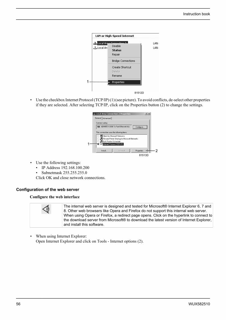
• A low warning level, shown on the display as <AL-L>.• A high warning level, shown on the display as <AL-H>.• A low shut-down level, shown on the display as <Sd-L>.• A high shut-down level, shown on the display as <Sd-H>.• Service level shown on the display as <SE-L>.• Service level shown on the display as <SE-H>.
Example of protection screens
Changing the settings
Starting from the Main screen (the example given describes the protection of the element outlet temperatures):
Press Scroll buttons (12) until <Pr.> followed by a number and the element outlet temperature pictograph isshown and press Enter button (13):
• The warning level for the high temperature warning level <AL-H> and the high temperature shut-downlevel <Sd-H> become visible. Use Scroll keys (12) to move between the warning level (<AL>) and theshut-down level (<Sd>), press the Enter button (13) to modify the value.
• An optional password may be required, the value starts blinking and Scroll buttons (12) can be used tomodify the value.
• Press the Enter button (13) to program the new value.
Programmable settings can only be modified within allowed limits.
Instruction book
52 WUX582510

3.31 Test screens
Display test
Starting from the Main screen, press Scroll buttons (12) until <t. 1> is shown and then press Enter button (13).
The display now shows all icons that can be displayed:
Safety valve test
In the test screen <t. 2>, a safety valve test is provided. The safety valves can only be tested after entering acode. Consult Atlas Copco if the safety valves are to be tested.
Production test
Test screen <t. 3> is only intended for production test. If the Main screen shows following screen, the controlleris in production test mode:
How to solve?
Use the Scroll buttons (12) and scroll to menu <t. 3>.
The screen shows:
Instruction book
WUX582510 53

Press the Enter button (13): the text starts blinking. Press enter again and the menu disappears.
3.32 Web serverAll Elektronikon controllers have a built-in web server that allows direct connection to the company networkor to a dedicated PC via a local area network (LAN). This allows to consult certain data and settings via a PCinstead of via the display of the controller.
Getting started
Make sure you are logged in as administrator.
• Use the internal network card from your computer or a USB to LAN adapter (see picture below).
USB to LAN adapter
• Use a UTP cable (CAT 5e) to connect to the controller (see picture below).
Instruction book
54 WUX582510

Configuration of the network card
• Go to My Network places (1).
• Click on View Network connections (1).
• Select the Local Area connection (1), which is connected to the controller.
• Click with the right button and select properties (1).
Instruction book
WUX582510 55
• Use the checkbox Internet Protocol (TCP/IP) (1) (see picture). To avoid conflicts, de-select other propertiesif they are selected. After selecting TCP/IP, click on the Properties button (2) to change the settings.
• Use the following settings:• IP Address 192.168.100.200• Subnetmask 255.255.255.0Click OK and close network connections.
Configuration of the web server
Configure the web interface
The internal web server is designed and tested for Microsoft® Internet Explorer 6, 7 and8. Other web browsers like Opera and Firefox do not support this internal web server.When using Opera or Firefox, a redirect page opens. Click on the hyperlink to connect tothe download server from Microsoft® to download the latest version of Internet Explorer,and install this software.
• When using Internet Explorer:Open Internet Explorer and click on Tools - Internet options (2).
Instruction book
56 WUX582510
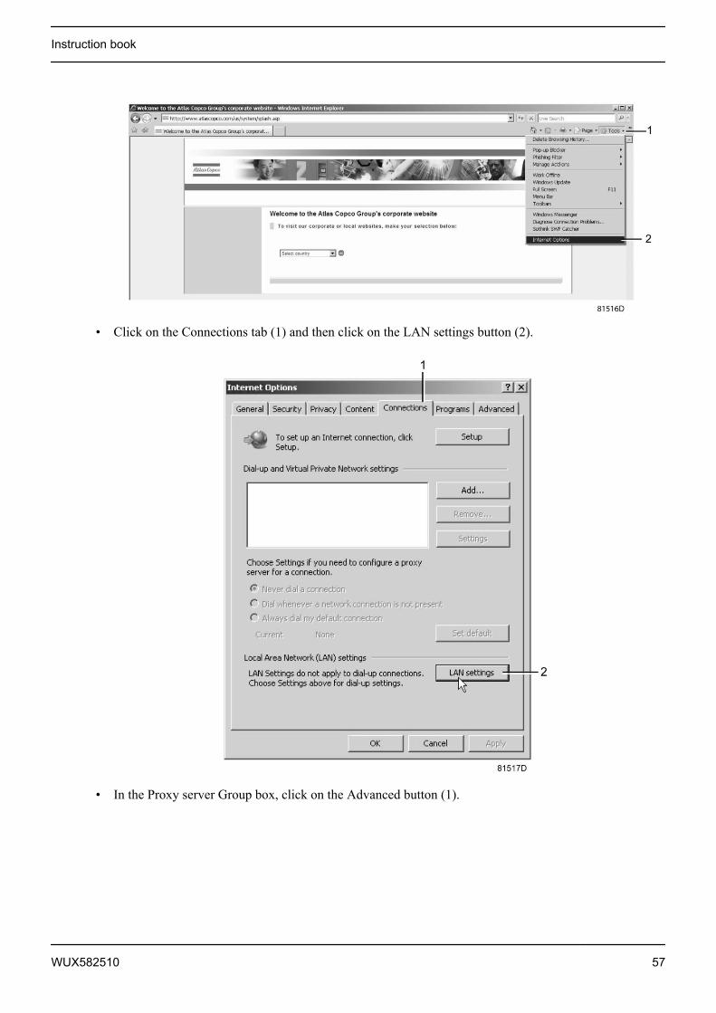
• Click on the Connections tab (1) and then click on the LAN settings button (2).
• In the Proxy server Group box, click on the Advanced button (1).
Instruction book
WUX582510 57
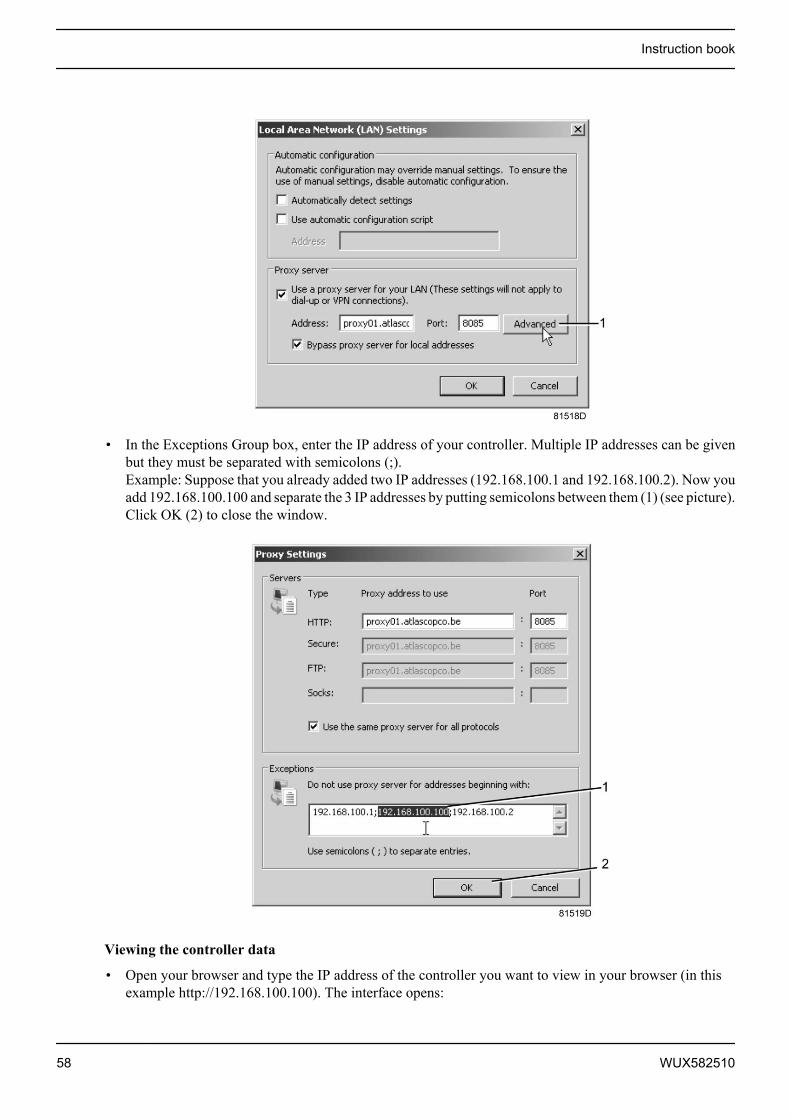
• In the Exceptions Group box, enter the IP address of your controller. Multiple IP addresses can be givenbut they must be separated with semicolons (;).Example: Suppose that you already added two IP addresses (192.168.100.1 and 192.168.100.2). Now youadd 192.168.100.100 and separate the 3 IP addresses by putting semicolons between them (1) (see picture).Click OK (2) to close the window.
Viewing the controller data
• Open your browser and type the IP address of the controller you want to view in your browser (in thisexample http://192.168.100.100). The interface opens:
Instruction book
58 WUX582510
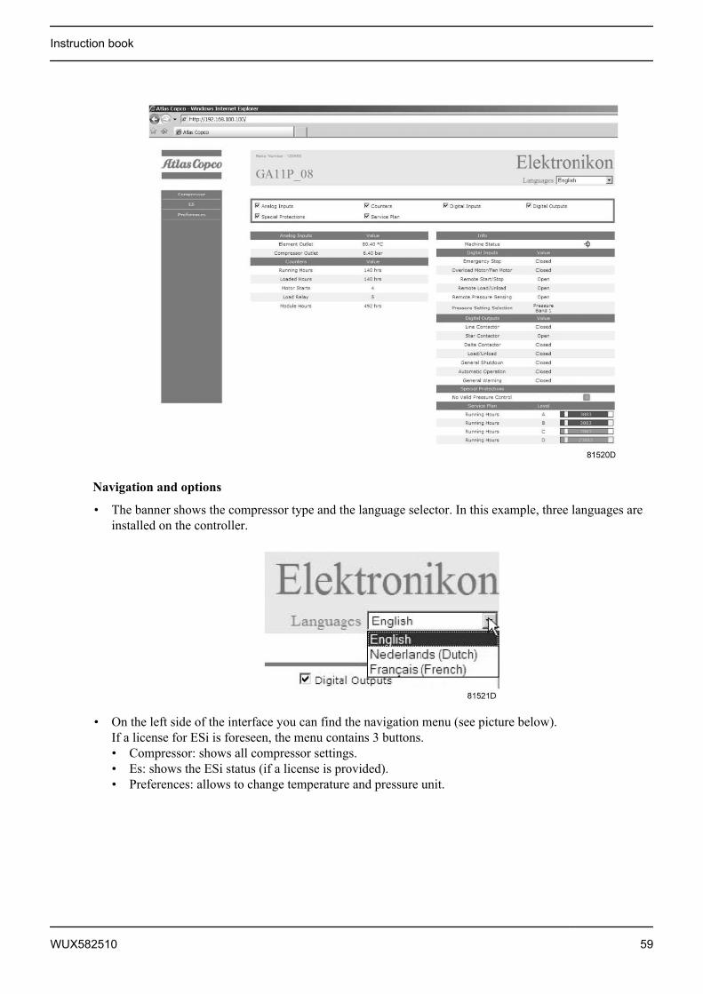
Navigation and options
• The banner shows the compressor type and the language selector. In this example, three languages areinstalled on the controller.
• On the left side of the interface you can find the navigation menu (see picture below).If a license for ESi is foreseen, the menu contains 3 buttons.• Compressor: shows all compressor settings.• Es: shows the ESi status (if a license is provided).• Preferences: allows to change temperature and pressure unit.
Instruction book
WUX582510 59
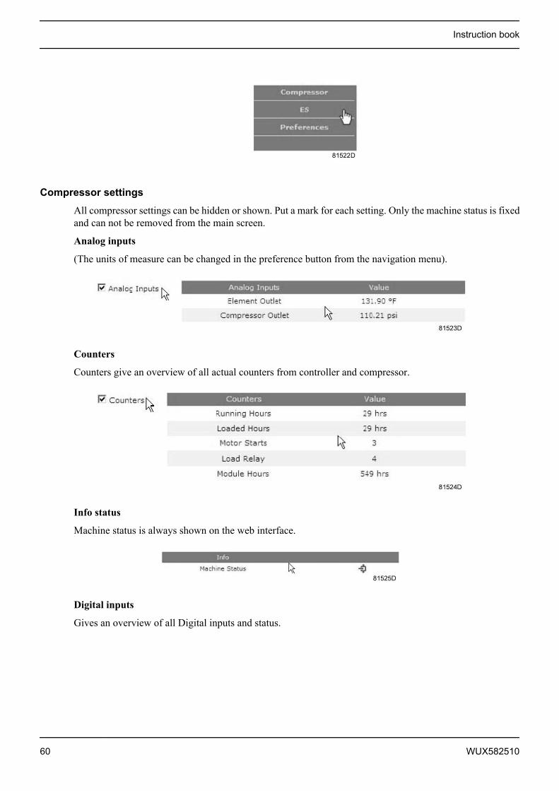
Compressor settings
All compressor settings can be hidden or shown. Put a mark for each setting. Only the machine status is fixedand can not be removed from the main screen.
Analog inputs
(The units of measure can be changed in the preference button from the navigation menu).
Counters
Counters give an overview of all actual counters from controller and compressor.
Info status
Machine status is always shown on the web interface.
Digital inputs
Gives an overview of all Digital inputs and status.
Instruction book
60 WUX582510

Digital outputs
Shows a list of all digital outputs and their status.
Special protections
Give an overview of all special protections of the compressor.
Service plan
Shows all levels of the service plan and status. This screen only shows the running hours. It is also possibleto show the actual status of the service interval.
ES screen controller
If an ESi license is provided, the button ES is shown in the navigation menu. At the left all compressors inthe ES and at the right the ES status are shown.
Instruction book
WUX582510 61
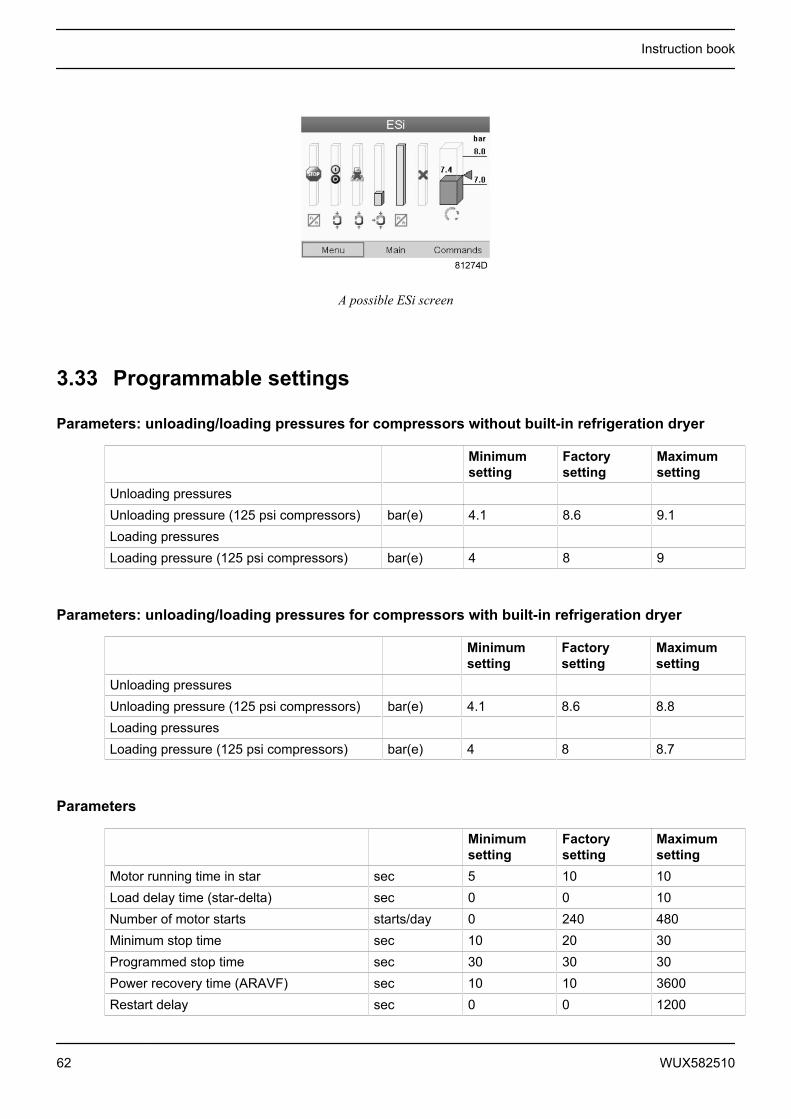
A possible ESi screen
3.33 Programmable settings
Parameters: unloading/loading pressures for compressors without built-in refrigeration dryer
Minimumsetting
Factorysetting
Maximumsetting
Unloading pressuresUnloading pressure (125 psi compressors) bar(e) 4.1 8.6 9.1Loading pressuresLoading pressure (125 psi compressors) bar(e) 4 8 9
Parameters: unloading/loading pressures for compressors with built-in refrigeration dryer
Minimumsetting
Factorysetting
Maximumsetting
Unloading pressuresUnloading pressure (125 psi compressors) bar(e) 4.1 8.6 8.8Loading pressuresLoading pressure (125 psi compressors) bar(e) 4 8 8.7
Parameters
Minimumsetting
Factorysetting
Maximumsetting
Motor running time in star sec 5 10 10Load delay time (star-delta) sec 0 0 10Number of motor starts starts/day 0 240 480Minimum stop time sec 10 20 30Programmed stop time sec 30 30 30Power recovery time (ARAVF) sec 10 10 3600Restart delay sec 0 0 1200
Instruction book
62 WUX582510
Minimumsetting
Factorysetting
Maximumsetting
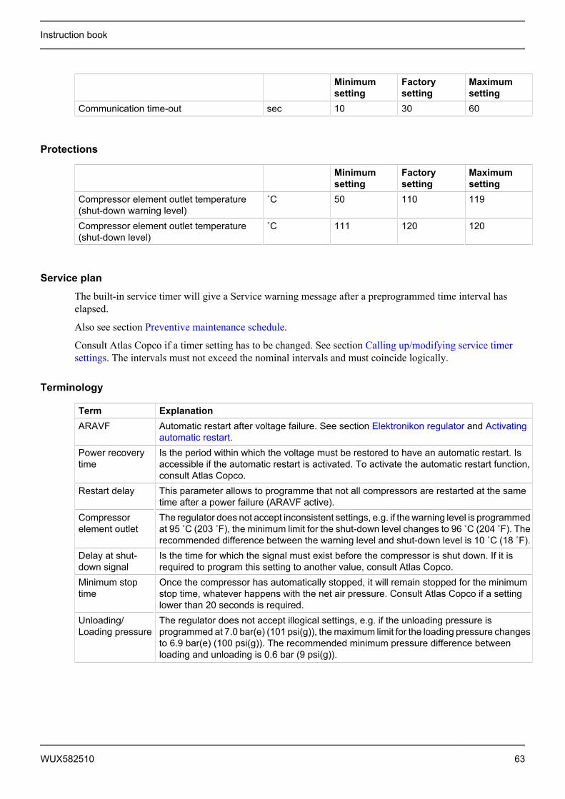
Communication time-out sec 10 30 60
Protections
Minimumsetting
Factorysetting
Maximumsetting
Compressor element outlet temperature(shut-down warning level)
˚C 50 110 119
Compressor element outlet temperature(shut-down level)
˚C 111 120 120
Service plan
The built-in service timer will give a Service warning message after a preprogrammed time interval haselapsed.
Also see section Preventive maintenance schedule.
Consult Atlas Copco if a timer setting has to be changed. See section Calling up/modifying service timersettings. The intervals must not exceed the nominal intervals and must coincide logically.
Terminology
Term ExplanationARAVF Automatic restart after voltage failure. See section Elektronikon regulator and Activating
automatic restart.Power recoverytime
Is the period within which the voltage must be restored to have an automatic restart. Isaccessible if the automatic restart is activated. To activate the automatic restart function,consult Atlas Copco.
Restart delay This parameter allows to programme that not all compressors are restarted at the sametime after a power failure (ARAVF active).
Compressorelement outlet
The regulator does not accept inconsistent settings, e.g. if the warning level is programmedat 95 ̊ C (203 ̊ F), the minimum limit for the shut-down level changes to 96 ̊ C (204 ̊ F). Therecommended difference between the warning level and shut-down level is 10 ˚C (18 ˚F).
Delay at shut-down signal
Is the time for which the signal must exist before the compressor is shut down. If it isrequired to program this setting to another value, consult Atlas Copco.
Minimum stoptime
Once the compressor has automatically stopped, it will remain stopped for the minimumstop time, whatever happens with the net air pressure. Consult Atlas Copco if a settinglower than 20 seconds is required.
Unloading/Loading pressure
The regulator does not accept illogical settings, e.g. if the unloading pressure isprogrammed at 7.0 bar(e) (101 psi(g)), the maximum limit for the loading pressure changesto 6.9 bar(e) (100 psi(g)). The recommended minimum pressure difference betweenloading and unloading is 0.6 bar (9 psi(g)).
Instruction book
WUX582510 63

4 Installation
4.1 Dimension drawings
GA 15 up to GA 22 Pack, Floor-mounted
Instruction book
64 WUX582510
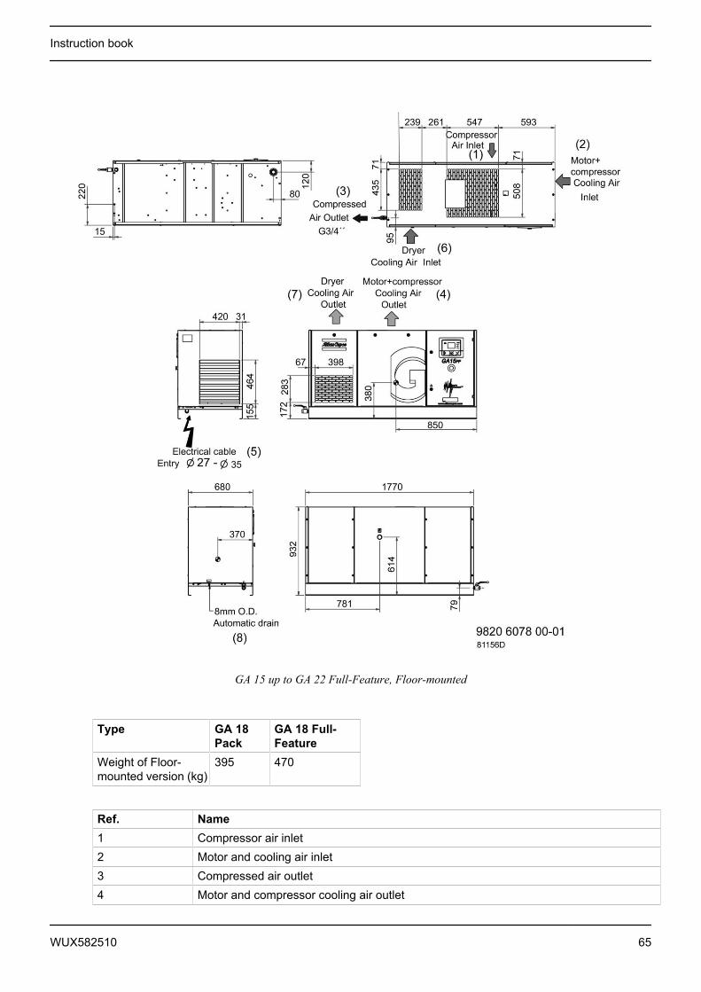
GA 15 up to GA 22 Full-Feature, Floor-mounted
Type GA 18Pack
GA 18 Full-Feature
Weight of Floor-mounted version (kg)
395 470
Ref. Name1 Compressor air inlet2 Motor and cooling air inlet3 Compressed air outlet4 Motor and compressor cooling air outlet
Instruction book
WUX582510 65
Ref. Name5 Electrical cable entry6 Dryer cooling air inlet7 Dryer cooling air outlet8 Automatic drain
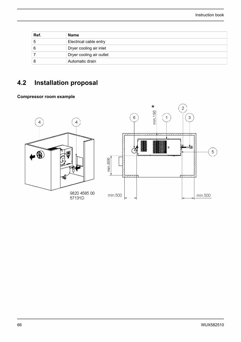
4.2 Installation proposal
Compressor room example
Instruction book
66 WUX582510
Description
1 Install the compressor unit on a solid, level floor suitable for taking the weight. Recommendedminimum distance between top of the unit and ceiling is 900 mm (35 in). Distance between unitand walls stated are minimum.* Recommended distance is 500 mm for easy access.Air receiver may not be bolted to the ground.
2 Position of the compressed air outlet valve (can be located on both sides of the air receiver).3 The pressure drop over the air delivery pipe can be calculated as follows:
Δp = (L x 450 x Qc1.85) / (d5 x P), with
d = Inner diameter of the pipe in mmΔp = Pressure drop in bar (recommended maximum: 0.1 bar (1.5 psi))L = Length of the pipe in mP = Absolute pressure at the compressor outlet in barQc = Free air delivery of the compressor in l/sIt is recommended that the connection of the compressor air outlet pipe is made on top of themain air net pipe in order to minimise carry-over of possible condensate residue.
4 Ventilation: the inlet grids and ventilation fan should be installed in such a way that anyrecirculation of cooling air to the compressor is avoided. The maximum air velocity through thegrids is 5 m/s (16.5 ft/s).Cooling air ducts are not allowed.The maximum air temperature at the compressor intake is 46 ˚C (115 ˚F) (minimum 0 ˚C / 32˚F).The ventilation capacity required to limit the compressor room temperature can becalculated from:Qv = 0.92 N/ΔTQv = Required ventilation capacity in m3/sN = Shaft input of compressor in kWΔT = Temperature increase in the compressor room in °C
5 Mains cable entry.To preserve the protection degree of the electric cubicle and to protect its components from dustfrom the environment, it is mandatory to use a proper cable gland when connecting the supplycable to the compressor.
Safety
The operator must apply all relevant safety precautions, including those mentioned in this book.
Outdoor/altitude operation
Fix speed compressors can be sold with option "rain protection". With this option, this compressor can beinstalled outside under a shelter, in frost free conditions. If frost might occur, the appropriate measures shouldbe taken to avoid damage to the machine and its ancillary equipment. In this case, and also if operating above1000 m (3300 ft), consult Atlas Copco.
Moving/lifting
Floor-mounted unit: the compressor can be moved by a lift truck. Take care not to damage any installedconnections under the frame while moving the truck or compressor. For lifting make sure that the forks arelong enough to give a stable support for the compressor.
Instruction book
WUX582510 67
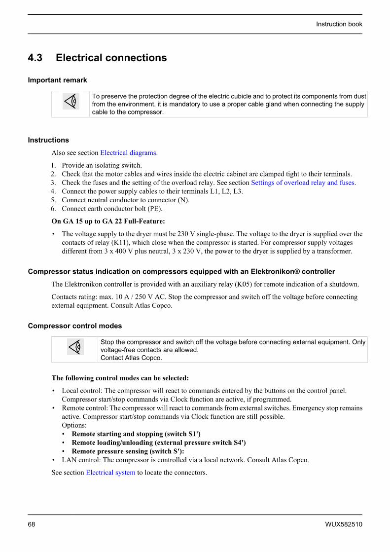
4.3 Electrical connections
Important remark
To preserve the protection degree of the electric cubicle and to protect its components from dustfrom the environment, it is mandatory to use a proper cable gland when connecting the supplycable to the compressor.
Instructions
Also see section Electrical diagrams.
1. Provide an isolating switch.2. Check that the motor cables and wires inside the electric cabinet are clamped tight to their terminals.3. Check the fuses and the setting of the overload relay. See section Settings of overload relay and fuses.4. Connect the power supply cables to their terminals L1, L2, L3.5. Connect neutral conductor to connector (N).6. Connect earth conductor bolt (PE).
On GA 15 up to GA 22 Full-Feature:
• The voltage supply to the dryer must be 230 V single-phase. The voltage to the dryer is supplied over thecontacts of relay (K11), which close when the compressor is started. For compressor supply voltagesdifferent from 3 x 400 V plus neutral, 3 x 230 V, the power to the dryer is supplied by a transformer.
Compressor status indication on compressors equipped with an Elektronikon® controller
The Elektronikon controller is provided with an auxiliary relay (K05) for remote indication of a shutdown.
Contacts rating: max. 10 A / 250 V AC. Stop the compressor and switch off the voltage before connectingexternal equipment. Consult Atlas Copco.
Compressor control modes
Stop the compressor and switch off the voltage before connecting external equipment. Onlyvoltage-free contacts are allowed.Contact Atlas Copco.
The following control modes can be selected:
• Local control: The compressor will react to commands entered by the buttons on the control panel.Compressor start/stop commands via Clock function are active, if programmed.
• Remote control: The compressor will react to commands from external switches. Emergency stop remainsactive. Compressor start/stop commands via Clock function are still possible.Options:• Remote starting and stopping (switch S1')• Remote loading/unloading (external pressure switch S4')• Remote pressure sensing (switch S'):
• LAN control: The compressor is controlled via a local network. Consult Atlas Copco.
See section Electrical system to locate the connectors.
Instruction book
68 WUX582510
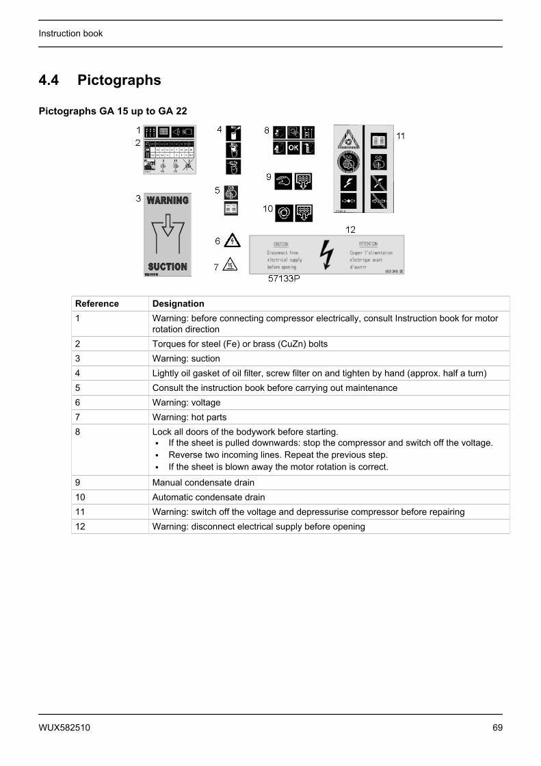
4.4 Pictographs
Pictographs GA 15 up to GA 22
Reference Designation1 Warning: before connecting compressor electrically, consult Instruction book for motor
rotation direction2 Torques for steel (Fe) or brass (CuZn) bolts3 Warning: suction4 Lightly oil gasket of oil filter, screw filter on and tighten by hand (approx. half a turn)5 Consult the instruction book before carrying out maintenance6 Warning: voltage7 Warning: hot parts8 Lock all doors of the bodywork before starting.
• If the sheet is pulled downwards: stop the compressor and switch off the voltage.• Reverse two incoming lines. Repeat the previous step.• If the sheet is blown away the motor rotation is correct.
9 Manual condensate drain10 Automatic condensate drain11 Warning: switch off the voltage and depressurise compressor before repairing12 Warning: disconnect electrical supply before opening
Instruction book
WUX582510 69
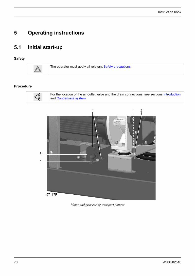
5 Operating instructions
5.1 Initial start-up
Safety
The operator must apply all relevant Safety precautions.
Procedure
For the location of the air outlet valve and the drain connections, see sections Introductionand Condensate system.
Motor and gear casing transport fixtures
Instruction book
70 WUX582510
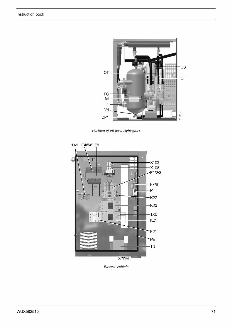
Position of oil level sight-glass
Electric cubicle
Instruction book
WUX582510 71

Location of the sheet
- Consult the sections Electric cable size,Installation proposal and Dimension drawings- The following transport fixtures, painted red, must be removed:
• Bolts (1)• Bushes (2)
- Check that the electrical connections correspond to the applicable codes and that all wires are clampedtight to their terminals.The installation must be earthed and protected against short circuits by fuses of the inert type in allphases. An isolating switch must be installed near the compressor.
- Check transformer (T1) for correct connection.For Full-Feature units except for voltages 230 V and 400 V + N: check transformer (T3) for correctconnection.Check the settings of drive motor overload relay (F21).Check that the motor overload relay is set for manual resetting.
- Fit air outlet valve (AV); see section Introduction for the location of the valve.Close the valve.Connect the air net to the valve.On compressors equipped with a dryer bypass, fit the air outlet valve to the dryer bypass pipe.
- Connect the condensate drain outlet(s) to a drain collector.See section Condensate system.
- For compressors with a DD or a DD and PD filter connect the automatic drain of the filters to a suitabledrain collector.
- Check the oil level. See section Oil and oil filter change.- Provide labels, warning the operator that:
• The compressor may automatically restart after voltage failure (if activated, consult Atlas Copco).• The compressor is automatically controlled and may be restarted automatically.
- Affix sheet (5) explaining the procedure for checking the motor rotation direction to the cooling air outletof the compressor. Consult section Dimension drawings.Switch on the voltage. Start the compressor and stop it immediately. Check the rotation direction ofdrive motor (M1) while the motor is coasting to a stop.Check the motor rotation of the motor using sheet (5). If the motor rotation direction is correct, the labelon the top grating will be blown upwards. If the sheet remains in place, the rotation direction is incorrect.If the rotation direction of the drive motor is incorrect, open the isolating switch and reverse two incomingelectric lines.Incorrect rotation direction of the drive motor may cause damage to the compressor.
- Check the programmed settings. On compressors equipped with an Elektronikon® controller, consultsection Programmable settings.
- Start and run the compressor for a few minutes. Check that the compressor operates normally.
Instruction book
72 WUX582510
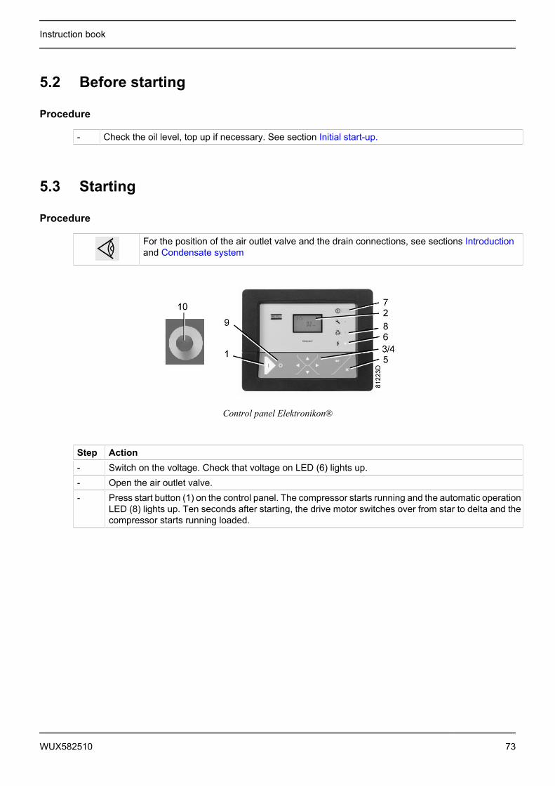
5.2 Before starting
Procedure
- Check the oil level, top up if necessary. See section Initial start-up.
5.3 Starting
Procedure
For the position of the air outlet valve and the drain connections, see sections Introductionand Condensate system
Control panel Elektronikon®
Step Action- Switch on the voltage. Check that voltage on LED (6) lights up.- Open the air outlet valve.- Press start button (1) on the control panel. The compressor starts running and the automatic operation
LED (8) lights up. Ten seconds after starting, the drive motor switches over from star to delta and thecompressor starts running loaded.
Instruction book
WUX582510 73
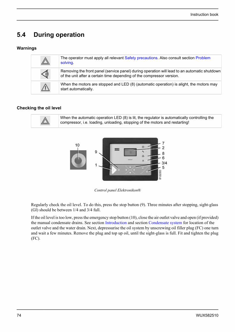
5.4 During operation
Warnings
The operator must apply all relevant Safety precautions. Also consult section Problemsolving.
Removing the front panel (service panel) during operation will lead to an automatic shutdownof the unit after a certain time depending of the compressor version.
When the motors are stopped and LED (8) (automatic operation) is alight, the motors maystart automatically.
Checking the oil level
When the automatic operation LED (8) is lit, the regulator is automatically controlling thecompressor, i.e. loading, unloading, stopping of the motors and restarting!
Control panel Elektronikon®
Regularly check the oil level. To do this, press the stop button (9). Three minutes after stopping, sight-glass(Gl) should be between 1/4 and 3/4 full.
If the oil level is too low, press the emergency stop button (10), close the air outlet valve and open (if provided)the manual condensate drains. See section Introduction and section Condensate system for location of theoutlet valve and the water drain. Next, depressurise the oil system by unscrewing oil filler plug (FC) one turnand wait a few minutes. Remove the plug and top up oil, until the sight-glass is full. Fit and tighten the plug(FC).
Instruction book
74 WUX582510
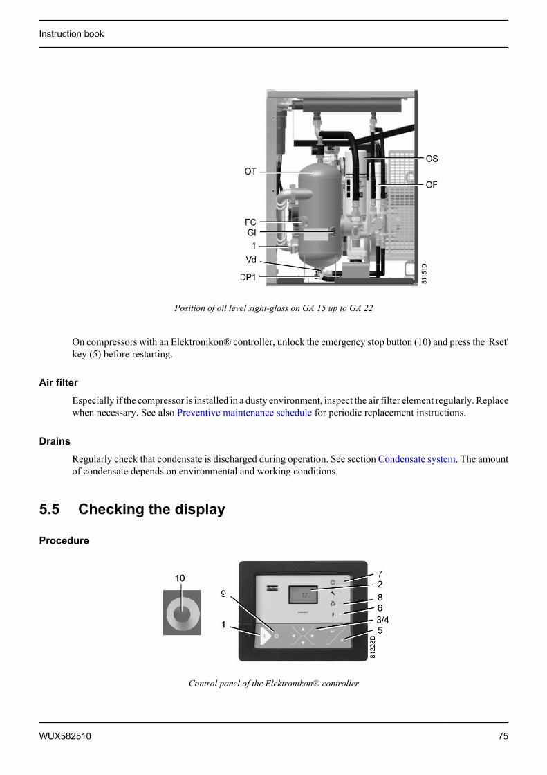
Position of oil level sight-glass on GA 15 up to GA 22
On compressors with an Elektronikon® controller, unlock the emergency stop button (10) and press the 'Rset'key (5) before restarting.
Air filter
Especially if the compressor is installed in a dusty environment, inspect the air filter element regularly. Replacewhen necessary. See also Preventive maintenance schedule for periodic replacement instructions.
Drains
Regularly check that condensate is discharged during operation. See section Condensate system. The amountof condensate depends on environmental and working conditions.
5.5 Checking the display
Procedure
Control panel of the Elektronikon® controller
Instruction book
WUX582510 75
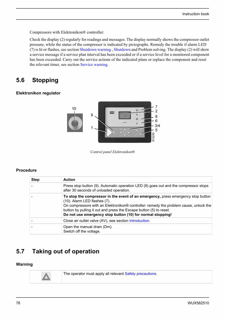
Compressors with Elektronikon® controller:
Check the display (2) regularly for readings and messages. The display normally shows the compressor outletpressure, while the status of the compressor is indicated by pictographs. Remedy the trouble if alarm LED(7) is lit or flashes, see section Shutdown warning , Shutdown and Problem solving. The display (2) will showa service message if a service plan interval has been exceeded or if a service level for a monitored componenthas been exceeded. Carry out the service actions of the indicated plans or replace the component and resetthe relevant timer, see section Service warning.
5.6 Stopping
Elektronikon regulator
Control panel Elektronikon®
Procedure
Step Action- Press stop button (9). Automatic operation LED (8) goes out and the compressor stops
after 30 seconds of unloaded operation.- To stop the compressor in the event of an emergency, press emergency stop button
(10). Alarm LED flashes (7).On compressors with an Elektronikon® controller: remedy the problem cause, unlock thebutton by pulling it out and press the Escape button (5) to reset.Do not use emergency stop button (10) for normal stopping!
- Close air outlet valve (AV), see section Introduction.- Open the manual drain (Dm).
Switch off the voltage.
5.7 Taking out of operation
Warning
The operator must apply all relevant Safety precautions.
Instruction book
76 WUX582510

Procedure
Step Action- Stop the compressor and close the air outlet valve.- Open the manual condensate drain (if provided). Consult section Condensate system to
locate the drain valve.- Switch off the voltage and disconnect the compressor from the mains.- Unscrew the oil filler plug only one turn to permit any pressure in the system to escape.
Consult section Oil and oil filter change to locate the filler plug.- Shut off and depressurise the part of the air net which is connected to the outlet valve.
Disconnect the compressor air outlet pipe from the air net.- Drain the oil.- Drain the condensate circuit and disconnect the condensate piping from the condensate
net.
Instruction book
WUX582510 77

6 Maintenance
6.1 Preventive maintenance schedule
Control panel
Control panel Elektronikon®
Warning
Before carrying out any maintenance, repair work or adjustments, proceed asfollows:• Stop the compressor.• Press the emergency stop button.• Switch off the voltage.• Close the air outlet valve and open, if provided, the manual condensate drain valves.• Depressurise the compressor.
For detailed instructions, see section Problem solving.The operator must apply all relevant Safety precautions.
Warranty - Product Liability
Use only authorised parts. Any damage or malfunction caused by the use of unauthorised parts is not coveredby Warranty or Product Liability.
Service kits
For overhauling or carrying out preventive maintenance, service kits are available (see section Service kits).
Service contracts
Atlas Copco offers several types of service contracts, relieving you of all preventive maintenance work.Consult your Atlas Copco Customer Centre.
General
When servicing, replace all removed gaskets, O-rings and washers.
Instruction book
78 WUX582510

Intervals
The local Atlas Copco Customer Centre may overrule the maintenance schedule, especially the serviceintervals, depending on the environmental and working conditions of the compressor.
The longer interval checks must also include the shorter interval checks.
Service actions for compressors with an Elektronikon® controller
Besides the daily and 3-monthly checks, the service operations are grouped in time intervals (running hours).The regulator has a programmable service timer. A service warning will appear when the service timer hasreached the programmed time interval; see section Service warning. In this case, check the running hours.Carry out the service operations corresponding to the running hours as specified in the schedule below. Resetthe service timer after servicing; see section Calling up/resetting the service timer.
Preventive maintenance schedule
Daily and 3-monthly check list
Period ActionDaily Check oil level.
Check readings on display.Check that condensate is discharged during loading.Drain condensate.Check air filter service indicator.Check the service indicator on the DDx and PDx filters (if provided).
3-monthly (1) Check coolers, clean if necessary.Remove the air filter element. Clean using an air jet and inspect. Replace damaged orheavily contaminated elements.Check the filter element of the electric cabinet (where applicable). Replace if necessaryOn Full-Feature units: Check condenser of dryer and clean if necessary.
(1): More frequently when operating in a dusty atmosphere.
Preventive Maintenance schedule programmed in the Elektronikon
Instruction book
WUX582510 79
Running hours Operation4000 (1) If Atlas Copco Roto-Inject Fluid is used, replace oil and oil filter.
If Atlas Copco Roto-Xtend Duty Fluid is used, replace the oil filter.4000 (1) Replace the oil separator element.
Replace the air filter element.Replace the filter element of the electric cabinet (where applicable).Clean coolers.Check pressure and temperature readings.Carry out a LED/display test.Check for leakages.On Pack compressors: remove, dismantle and clean float valve of condensate trap. SeesectionCondensate system.On Full-Feature compressors, open the manual drain valve (Dm) to clean the filter of theautomatic drain.
4000 (1) On Full-Feature units: clean condenser of dryer.yearly Test temperature shut-down function.
Test safety valve.8000 (2) If Atlas Copco Roto-Xtend Duty Fluid is used, replace the oil.
(1): or yearly, whichever comes first
(2): or every 2 years, whichever comes first
Important
• Always consult Atlas Copco if a timer setting has to be changed.• For the change interval of oil and oil filter in extreme conditions of temperature,
humidity or cooling air, consult your Atlas Copco Customer Centre.• Any leakage should be attended to immediately. Damaged hoses or flexible joints must
be replaced.
6.2 Oil specificationsIt is strongly recommended to use genuine Atlas Copco Lubricants. They are the result of years of fieldexperience and research. See section Preventive maintenance schedule for the advised replacement intervalsand consult your Spare Parts list for part number information.
Never mix lubricants of different brands or types as they may not be compatible and theoil mix will have inferior properties. A label, indicating the type of oil filled ex factory, isstuck on the air receiver/oil tank.
Roto-Inject Fluid
Atlas Copco's Roto-Inject Fluid is a specially developed lubricant for use in single stage oil-injected screwcompressors. Its specific composition keeps the compressor in excellent condition. Roto-Inject Fluid can beused for compressors operating at ambient temperatures between 0 ˚C (32 ˚F) and 40 ˚C (104 ˚F). If thecompressor is regularly operating in ambient temperatures between 40 °C and 46 °C (115 °F), oil lifetime isreduced significantly. In such case it is recommended to use Roto-Xtend Duty Fluid.
Instruction book
80 WUX582510
Roto-Xtend Duty Fluid
Atlas Copco's Roto-Xtend Duty Fluid is a high quality synthetic lubricant for oil-injected screw compressorswhich keeps the compressor in excellent condition. Because of its excellent oxidation stability, Roto-XtendDuty Fluid can be used for compressors operating at ambient temperatures between 0 ˚C (32 ˚F) and 46 ˚C(115 ˚F).
6.3 Storage after installation
Procedure
Run the compressor regularly, e.g. twice a week, until warm. Load and unload the compressor a few times.
6.4 Service kits
Service kits
For overhauling and for preventive maintenance, a wide range of service kits is available. Service kits compriseall parts required for servicing the component and offer the benefits of genuine Atlas Copco parts whilekeeping the maintenance budget low.
Also a full range of extensively tested lubricants, suitable for your specific needs is available to keep thecompressor in excellent condition.
Consult the Spare Parts List for part numbers.
6.5 Disposal of used material
Used filters or any other used material (e.g. desiccant, lubricants, cleaning rags, machine parts, etc.) must bedisposed of in an environmentally friendly and safe manner, and in line with the local recommendations andenvironmental legislation.
Instruction book
WUX582510 81

7 Adjustments and servicing procedures
7.1 Drive motor
General
Keep the outside of the electric motor clean for efficient cooling. If necessary, remove dust with a brush and/or compressed air jet.
Bearing maintenance
The motor bearings are greased for life.
7.2 Air filter
Location of air filter
Air filter, GA 15 up to GA 22
Recommendations
1. Never remove the element while the compressor is running.2. For minimum downtime, replace the dirty element by a new one.3. Discard the element when damaged.
Procedure
1. Stop the compressor. Switch off the voltage.2. On Pack units: remove the side panel.
On Full-Feature units: remove the front panel.3. Remove the air filter assembly.4. Remove the cover of air filter (AF) by turning it anti-clockwise. Remove the filter element. If necessary,
clean the cover.5. Fit the new element and the cover.6. Reset the air filter service warning.
Instruction book
82 WUX582510

For compressors equipped with an Elektronikon® regulator, see section Service warning.
7.3 Oil and oil filter change
Warning
The operator must apply all relevant Safety precautions.
Procedure
Oil system components of GA 15 up to GA 22
1. Run the compressor until warm. Stop the compressor. Close the air outlet valve and switch off the voltage.Depressurise the compressor by opening manual drain valve(s) (Dm, Dm1). Wait a few minutes anddepressurise the air receiver/oil (AR) tank by unscrewing oil filler plug (FC) just one turn to permit anypressure in the system to escape.
2. Remove oil drain plug (DP1) and drain the oil by opening valve (Vd). Also remove the drain plug onflexible (1) near the element outlet. To drain the oil in the oil cooler, remove the vent plug on the oil cooler.As an alternative, it is also possible to loosen the flexible hoses to the oil cooler to allow air to enter thecooler. Close the drain valve (Vd) and fit the plugs after draining.
3. Collect the oil and deliver it to the local collection service. Refit and tighten the drain and vent plugs afterdraining.Re-tighten the top connection of the oil cooler.
4. Remove the oil filter (OF). Clean the seat on the manifold. Oil the gasket of the new filter and screw itinto place. Tighten firmly by hand.
5. Remove filler plug (FC).Insert an elbow coupling in the filler plug (FC) for easy filling. Fill the oil tank (OT) with oil until thelevel reaches the middle of sight-glass (Gl).Take care that no dirt drops into the system. Refit and tighten filler plug (FC).
Instruction book
WUX582510 83
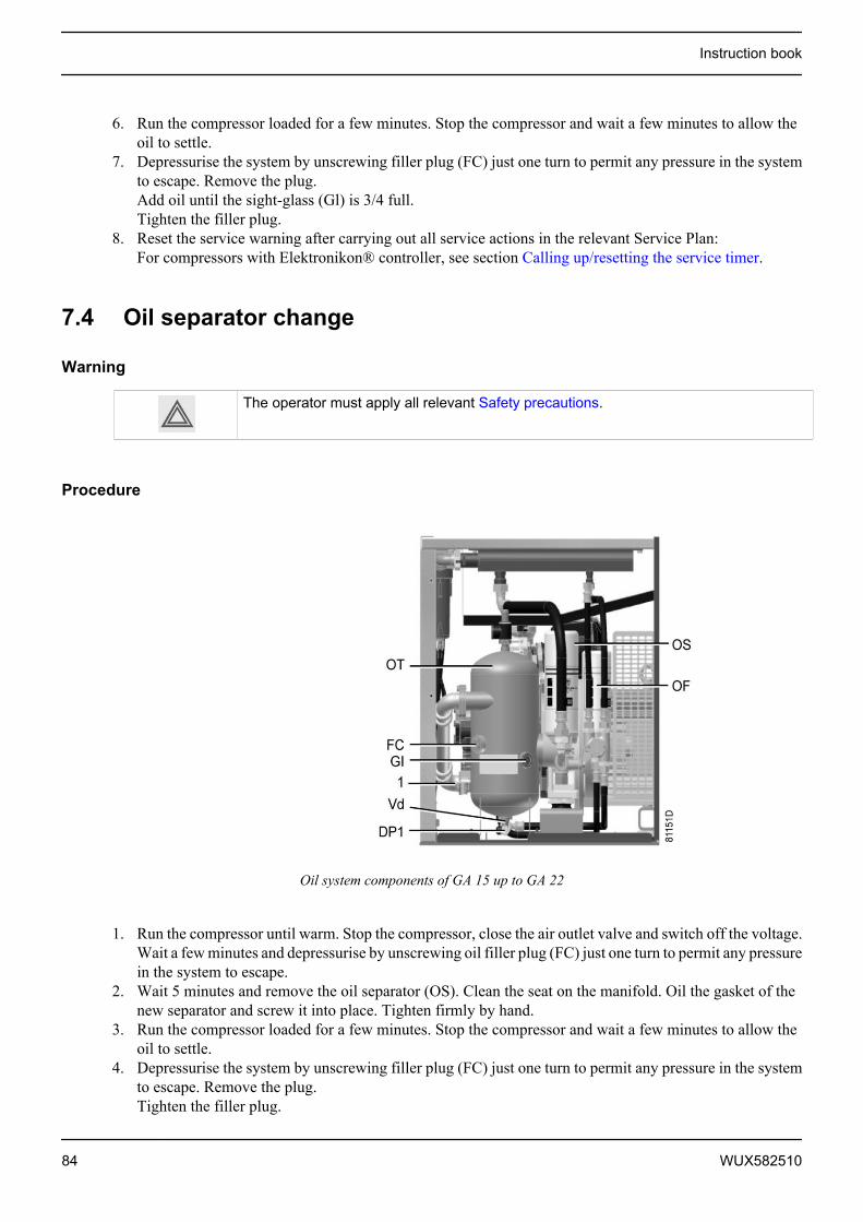
6. Run the compressor loaded for a few minutes. Stop the compressor and wait a few minutes to allow theoil to settle.
7. Depressurise the system by unscrewing filler plug (FC) just one turn to permit any pressure in the systemto escape. Remove the plug.Add oil until the sight-glass (Gl) is 3/4 full.Tighten the filler plug.
8. Reset the service warning after carrying out all service actions in the relevant Service Plan:For compressors with Elektronikon® controller, see section Calling up/resetting the service timer.
7.4 Oil separator change
Warning
The operator must apply all relevant Safety precautions.
Procedure
Oil system components of GA 15 up to GA 22
1. Run the compressor until warm. Stop the compressor, close the air outlet valve and switch off the voltage.Wait a few minutes and depressurise by unscrewing oil filler plug (FC) just one turn to permit any pressurein the system to escape.
2. Wait 5 minutes and remove the oil separator (OS). Clean the seat on the manifold. Oil the gasket of thenew separator and screw it into place. Tighten firmly by hand.
3. Run the compressor loaded for a few minutes. Stop the compressor and wait a few minutes to allow theoil to settle.
4. Depressurise the system by unscrewing filler plug (FC) just one turn to permit any pressure in the systemto escape. Remove the plug.Tighten the filler plug.
Instruction book
84 WUX582510

5. Reset the service timer:For compressors equipped with an Elektronikon® regulator, see section Service warning.
7.5 Coolers
General
Keep the coolers clean to maintain their efficiency.
Never use a high pressure water jet to clean the compressor.
Instructions for air-cooled compressors
• Stop the compressor, close the air outlet valve and switch off the voltage.• Cover all parts under the coolers.• Remove any dirt from the coolers with a fibre brush. Never use a wire brush or metal objects.• Next, clean with an air jet in the reverse direction to normal flow. Use low pressure air. If necessary, the
pressure may be increased up to 6 bar(e) (87 psig).• If it is necessary to wash the coolers with a cleaning agent, consult Atlas Copco.
7.6 Safety valves
Location of safety valve
GA 15 up to GA 22
Instruction book
WUX582510 85
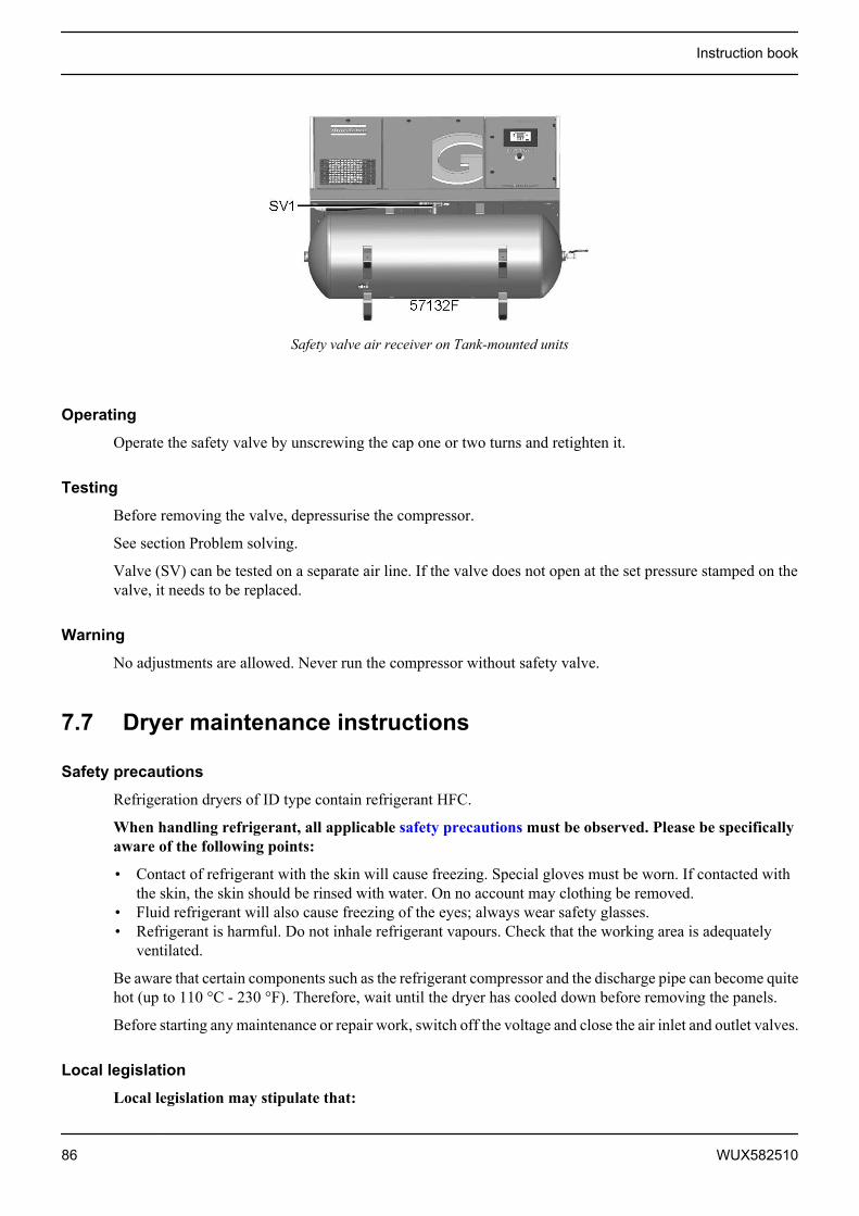
Safety valve air receiver on Tank-mounted units
Operating
Operate the safety valve by unscrewing the cap one or two turns and retighten it.
Testing
Before removing the valve, depressurise the compressor.
See section Problem solving.
Valve (SV) can be tested on a separate air line. If the valve does not open at the set pressure stamped on thevalve, it needs to be replaced.
Warning
No adjustments are allowed. Never run the compressor without safety valve.
7.7 Dryer maintenance instructions
Safety precautions
Refrigeration dryers of ID type contain refrigerant HFC.
When handling refrigerant, all applicable safety precautions must be observed. Please be specificallyaware of the following points:
• Contact of refrigerant with the skin will cause freezing. Special gloves must be worn. If contacted withthe skin, the skin should be rinsed with water. On no account may clothing be removed.
• Fluid refrigerant will also cause freezing of the eyes; always wear safety glasses.• Refrigerant is harmful. Do not inhale refrigerant vapours. Check that the working area is adequately
ventilated.
Be aware that certain components such as the refrigerant compressor and the discharge pipe can become quitehot (up to 110 °C - 230 °F). Therefore, wait until the dryer has cooled down before removing the panels.
Before starting any maintenance or repair work, switch off the voltage and close the air inlet and outlet valves.
Local legislation
Local legislation may stipulate that:
Instruction book
86 WUX582510

• Work on the refrigerant circuit of the cooling dryer or on any equipment which influences its functionmust be undertaken by an authorised control body.
• The installation should be checked once a year by an authorised control body.
General
For all references see section Introduction.
The following remarks should be kept in mind:
• Keep the dryer clean.• Brush or blow off the finned surface of condenser monthly.• Inspect and clean the electronic condensate drain monthly.
Instruction book
WUX582510 87

8 Problem solving
Warning
Before carrying out any maintenance, repair work or adjustment, press the stop button,wait until the compressor has stopped (approx. 30 seconds), press the emergency stopbutton and switch off the voltage. Close the air outlet valve, open manual drain (Dm) onPack units and also open the manual condensate drain (Dm1) on Tank-mounted units.Depressurise the compressor by opening the oil filler plug (FC) one turn.For location of components, see sections:• Introduction• Condensate system• Initial start-up
Open and lock the isolating switch. The air outlet valve can be locked during maintenance or repair as follows:
• Close the valve.• Remove the screw fixing the handle with the wrench delivered with the compressor.• Lift the handle and turn it until the slot of the handle fits over the blocking edge on the
valve body.• Fit the screw.
The operator must apply all relevant Safety precautions.
Faults and remedies, compressor
On compressors equipped with an Elektronikon® controller, if the alarm LED is lit or flashes, consult sectionsShutdown warning , Shutdown and Service warning.
Condition Fault RemedyCompressor starts running, butdoes not load after a delay time
Solenoid valve out of order Replace valve
Inlet valve stuck in closed position Have valve checked Leak in control air tubes Replace leaking tubes Minimum pressure valve leaking
(when net is depressurised)Have valve checked
Compressor does not unload,safety valve blows
Solenoid valve out of order Replace valveInlet valve does not close Have valve checked
Condensate is not discharged fromcondensate separator duringloading
Discharge tube clogged Check and correct as necessary
On Pack units: float valvemalfunctioning
Remove float valve assembly,clean and check
On Full-Feature units: electronicdrain malfunctioning
Press test button, replace ifnecessary
Compressor air output or pressurebelow normal
Air consumption exceeds air deliveryof compressor
Check equipment connected
Choked air filter element Replace filter element Solenoid valve malfunctioning Replace valve Leak in control air tubes Replace leaking tubes
Instruction book
88 WUX582510

Condition Fault Remedy Inlet valve does not fully open Have valve checked Oil separator clogged Replace oil separator element Air leakage Have leaks repaired Safety valve leaking Have valve replaced Compressor element out of order Consult Atlas CopcoExcessive oil consumption; oilcarry-over through discharge line
Incorrect oil causing foam Change to correct oil
Oil separator defective Replace oil separator element Malfunctioning of the scavenge line Replace non-return valve in the
scavenge lineSafety valve blows after loading Inlet valve malfunctioning Have valve checked Minimum pressure valve
malfunctioningHave valve checked
Safety valve out of order Have valve replaced Compressor element out of order Consult Atlas Copco Oil separator element clogged Replace oil separator elementCompressor element outlettemperature or delivery airtemperature above normal
Oil level too low Check and correct
On air-cooled compressors,insufficient cooling air or cooling airtemperature too high
Check for cooling air restriction orimprove ventilation of thecompressor room. Avoidrecirculation of cooling air. Ifinstalled, check capacity ofcompressor room fan
Oil cooler clogged Clean cooler Bypass valve malfunctioning Have valve tested Air cooler clogged Clean cooler Compressor element out of order Consult Atlas Copco Customer
Centre
Faults and remedies, dryer
For all references hereafter, consult section Air dryer.
Condition Fault RemedyPressure dew point too high Air inlet temperature too high Check and correct; if necessary, clean the
aftercooler of the compressor Ambient temperature too high Check and correct; if necessary, draw
cooling air via a duct from a cooler place orrelocate the compressor
Shortage of refrigerant Have circuit checked for leaks and recharged Refrigerant compressor does
not runSee below
Evaporator pressure too high See below Condenser pressure too high See below
Instruction book
WUX582510 89
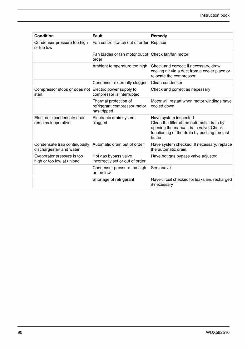
Condition Fault RemedyCondenser pressure too highor too low
Fan control switch out of order Replace
Fan blades or fan motor out oforder
Check fan/fan motor
Ambient temperature too high Check and correct; if necessary, drawcooling air via a duct from a cooler place orrelocate the compressor
Condenser externally clogged Clean condenserCompressor stops or does notstart
Electric power supply tocompressor is interrupted
Check and correct as necessary
Thermal protection ofrefrigerant compressor motorhas tripped
Motor will restart when motor windings havecooled down
Electronic condensate drainremains inoperative
Electronic drain systemclogged
Have system inspectedClean the filter of the automatic drain byopening the manual drain valve. Checkfunctioning of the drain by pushing the testbutton.
Condensate trap continuouslydischarges air and water
Automatic drain out of order Have system checked. If necessary, replacethe automatic drain.
Evaporator pressure is toohigh or too low at unload
Hot gas bypass valveincorrectly set or out of order
Have hot gas bypass valve adjusted
Condenser pressure too highor too low
See above
Shortage of refrigerant Have circuit checked for leaks and rechargedif necessary
Instruction book
90 WUX582510
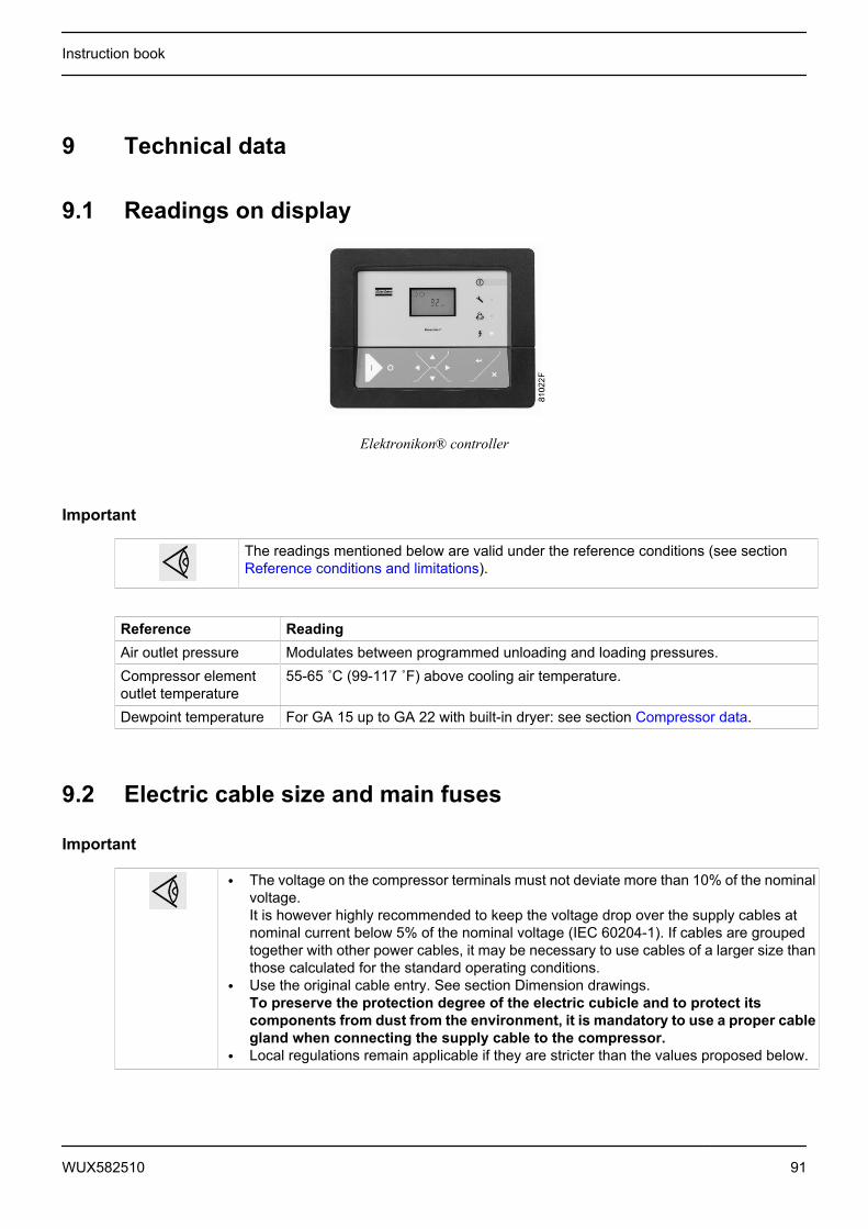
9 Technical data
9.1 Readings on display
Elektronikon® controller
Important
The readings mentioned below are valid under the reference conditions (see sectionReference conditions and limitations).
Reference ReadingAir outlet pressure Modulates between programmed unloading and loading pressures.Compressor elementoutlet temperature
55-65 ˚C (99-117 ˚F) above cooling air temperature.
Dewpoint temperature For GA 15 up to GA 22 with built-in dryer: see section Compressor data.
9.2 Electric cable size and main fuses
Important
• The voltage on the compressor terminals must not deviate more than 10% of the nominalvoltage.It is however highly recommended to keep the voltage drop over the supply cables atnominal current below 5% of the nominal voltage (IEC 60204-1). If cables are groupedtogether with other power cables, it may be necessary to use cables of a larger size thanthose calculated for the standard operating conditions.
• Use the original cable entry. See section Dimension drawings.To preserve the protection degree of the electric cubicle and to protect itscomponents from dust from the environment, it is mandatory to use a proper cablegland when connecting the supply cable to the compressor.
• Local regulations remain applicable if they are stricter than the values proposed below.
Instruction book
WUX582510 91
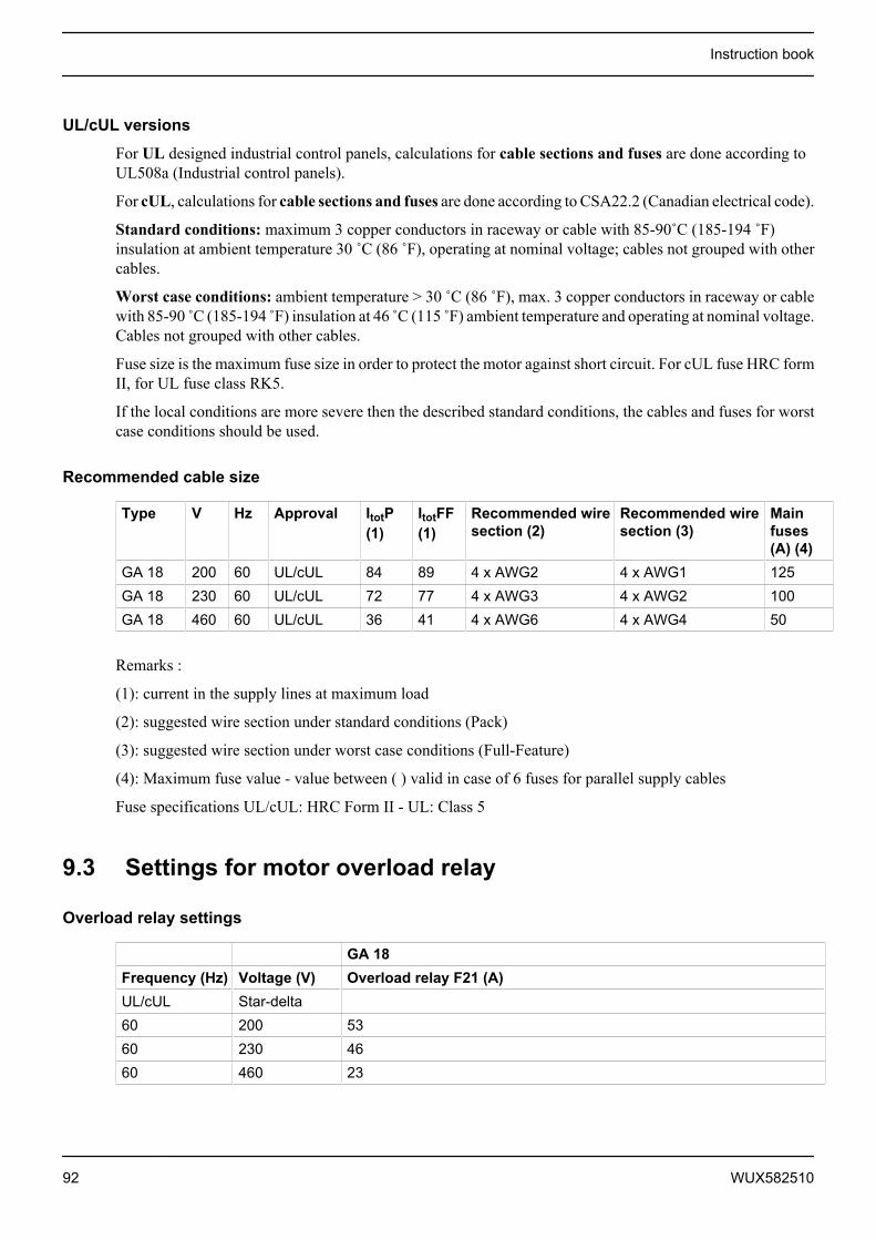
UL/cUL versions
For UL designed industrial control panels, calculations for cable sections and fuses are done according toUL508a (Industrial control panels).
For cUL, calculations for cable sections and fuses are done according to CSA22.2 (Canadian electrical code).
Standard conditions: maximum 3 copper conductors in raceway or cable with 85-90˚C (185-194 ˚F)insulation at ambient temperature 30 ˚C (86 ˚F), operating at nominal voltage; cables not grouped with othercables.
Worst case conditions: ambient temperature > 30 ˚C (86 ˚F), max. 3 copper conductors in raceway or cablewith 85-90 ̊ C (185-194 ̊ F) insulation at 46 ̊ C (115 ̊ F) ambient temperature and operating at nominal voltage.Cables not grouped with other cables.
Fuse size is the maximum fuse size in order to protect the motor against short circuit. For cUL fuse HRC formII, for UL fuse class RK5.
If the local conditions are more severe then the described standard conditions, the cables and fuses for worstcase conditions should be used.
Recommended cable size
Type V Hz Approval ItotP(1)
ItotFF(1)
Recommended wiresection (2)
Recommended wiresection (3)
Mainfuses(A) (4)
GA 18 200 60 UL/cUL 84 89 4 x AWG2 4 x AWG1 125GA 18 230 60 UL/cUL 72 77 4 x AWG3 4 x AWG2 100GA 18 460 60 UL/cUL 36 41 4 x AWG6 4 x AWG4 50
Remarks :
(1): current in the supply lines at maximum load
(2): suggested wire section under standard conditions (Pack)
(3): suggested wire section under worst case conditions (Full-Feature)
(4): Maximum fuse value - value between ( ) valid in case of 6 fuses for parallel supply cables
Fuse specifications UL/cUL: HRC Form II - UL: Class 5
9.3 Settings for motor overload relay
Overload relay settings
GA 18Frequency (Hz) Voltage (V) Overload relay F21 (A)UL/cUL Star-delta60 200 5360 230 4660 460 23
Instruction book
92 WUX582510
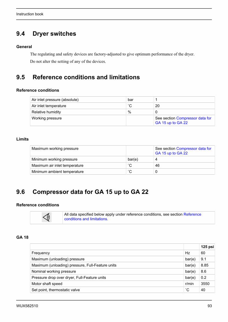
9.4 Dryer switches
General
The regulating and safety devices are factory-adjusted to give optimum performance of the dryer.
Do not alter the setting of any of the devices.
9.5 Reference conditions and limitations
Reference conditions
Air inlet pressure (absolute) bar 1Air inlet temperature ˚C 20Relative humidity % 0Working pressure See section Compressor data for
GA 15 up to GA 22
Limits
Maximum working pressure See section Compressor data forGA 15 up to GA 22
Minimum working pressure bar(e) 4Maximum air inlet temperature ˚C 46Minimum ambient temperature ˚C 0
9.6 Compressor data for GA 15 up to GA 22
Reference conditions
All data specified below apply under reference conditions, see section Referenceconditions and limitations.
GA 18
125 psiFrequency Hz 60Maximum (unloading) pressure bar(e) 9.1Maximum (unloading) pressure, Full-Feature units bar(e) 8.85Nominal working pressure bar(e) 8.6Pressure drop over dryer, Full-Feature units bar(e) 0.2Motor shaft speed r/min 3550Set point, thermostatic valve ˚C 40
Instruction book
WUX582510 93
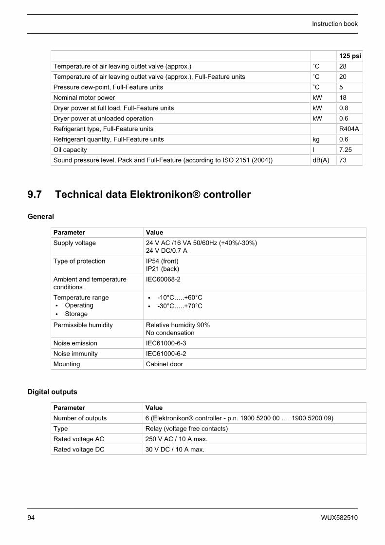
125 psiTemperature of air leaving outlet valve (approx.) ˚C 28Temperature of air leaving outlet valve (approx.), Full-Feature units ˚C 20Pressure dew-point, Full-Feature units ˚C 5Nominal motor power kW 18Dryer power at full load, Full-Feature units kW 0.8Dryer power at unloaded operation kW 0.6Refrigerant type, Full-Feature units R404ARefrigerant quantity, Full-Feature units kg 0.6Oil capacity l 7.25Sound pressure level, Pack and Full-Feature (according to ISO 2151 (2004)) dB(A) 73
9.7 Technical data Elektronikon® controller
General
Parameter ValueSupply voltage 24 V AC /16 VA 50/60Hz (+40%/-30%)
24 V DC/0.7 AType of protection IP54 (front)
IP21 (back)Ambient and temperatureconditions
IEC60068-2
Temperature range• Operating• Storage
• -10°C…..+60°C• -30°C…..+70°C
Permissible humidity Relative humidity 90%No condensation
Noise emission IEC61000-6-3Noise immunity IEC61000-6-2Mounting Cabinet door
Digital outputs
Parameter ValueNumber of outputs 6 (Elektronikon® controller - p.n. 1900 5200 00 …. 1900 5200 09)Type Relay (voltage free contacts)Rated voltage AC 250 V AC / 10 A max.Rated voltage DC 30 V DC / 10 A max.
Instruction book
94 WUX582510
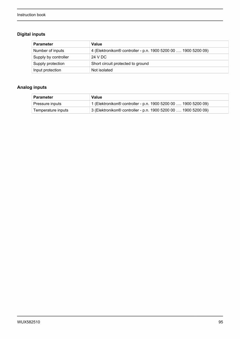
Digital inputs
Parameter ValueNumber of inputs 4 (Elektronikon® controller - p.n. 1900 5200 00 …. 1900 5200 09)Supply by controller 24 V DCSupply protection Short circuit protected to groundInput protection Not isolated
Analog inputs
Parameter ValuePressure inputs 1 (Elektronikon® controller - p.n. 1900 5200 00 …. 1900 5200 09)Temperature inputs 3 (Elektronikon® controller - p.n. 1900 5200 00 …. 1900 5200 09)
Instruction book
WUX582510 95
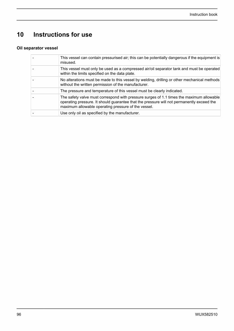
10 Instructions for use
Oil separator vessel
- This vessel can contain pressurised air; this can be potentially dangerous if the equipment ismisused.
- This vessel must only be used as a compressed air/oil separator tank and must be operatedwithin the limits specified on the data plate.
- No alterations must be made to this vessel by welding, drilling or other mechanical methodswithout the written permission of the manufacturer.
- The pressure and temperature of this vessel must be clearly indicated.- The safety valve must correspond with pressure surges of 1.1 times the maximum allowable
operating pressure. It should guarantee that the pressure will not permanently exceed themaximum allowable operating pressure of the vessel.
- Use only oil as specified by the manufacturer.
Instruction book
96 WUX582510
11 Guidelines for inspection
Guidelines
On the Declaration of Conformity / Declaration by the Manufacturer, the harmonised and/or other standardsthat have been used for the design are shown and/or referred to.
The Declaration of Conformity / Declaration by the Manufacturer is part of the documentation that is suppliedwith this compressor.
Local legal requirements and/or use outside the limits and/or conditions as specified by the manufacturer mayrequire other inspection periods as mentioned below.
Instruction book
WUX582510 97
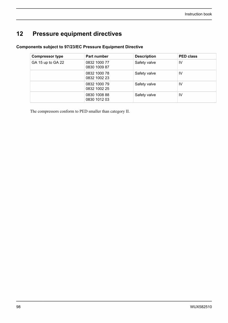
12 Pressure equipment directives
Components subject to 97/23/EC Pressure Equipment Directive
Compressor type Part number Description PED classGA 15 up to GA 22 0832 1000 77
0830 1009 87Safety valve IV
0832 1000 780832 1002 23
Safety valve IV
0832 1000 790832 1002 25
Safety valve IV
0830 1008 880830 1012 03
Safety valve IV
The compressors conform to PED smaller than category II.
Instruction book
98 WUX582510
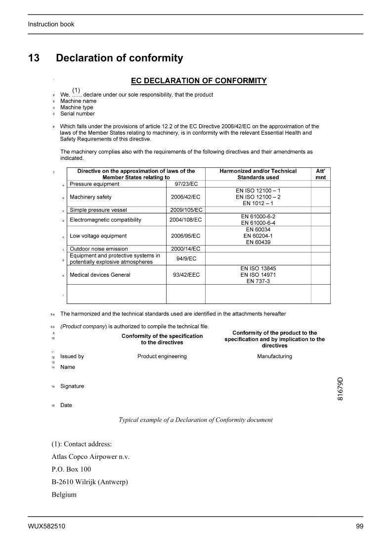
13 Declaration of conformity
Typical example of a Declaration of Conformity document
(1): Contact address:
Atlas Copco Airpower n.v.
P.O. Box 100
B-2610 Wilrijk (Antwerp)
Belgium
Instruction book
WUX582510 99


In order to be First in Mind—First in Choice® for all your qualitycompressed air needs, Atlas Copco delivers the products andservices that help to increase your business’ efficiency andprofitability.
Atlas Copco's pursuit of innovation never ceases, driven by ourneed for reliability and efficiency. Always working with you, we arecommitted to providing you the customized quality air solution thatis the driving force behind your business.
www.atlascopco.com


