22
Galilee Boat Model Galilee Boat Model Dick Webber Dick Webber

Galilee Boat ModelGalilee Boat Model
Dick WebberDick Webber

2
Table of Contents
Introduction .................................................................... 3
Making the Keel ............................................................... 4
Frame Shapes and Material ............................................... 4
Construction Jig ............................................................... 5
Frame Construction .......................................................... 5
Fastening Planks to Frames ............................................... 7
Clamps ........................................................................... 7
Steam Planks .................................................................. 8
Caprails .......................................................................... 9
Inside Rails ..................................................................... 9
Sail, Rigging, Decks and Ceiling ......................................... 9
Ceilings ........................................................................ 11
Oars and Steering .......................................................... 11
Figures ......................................................................... 11
Display Stand ................................................................ 11
Finishing ....................................................................... 12
Bibliography .................................................................. 13
Sources ........................................................................ 13
Additional Reading ......................................................... 13
Boat Drawings ............................................................... 14
Galilee Boat Model
Copyright © 2009 by Dick Webber

3
Galilee Boat Model
Dick Webber, 2009
I was fortunate to visit Galilee in 1995 and 1996 and see the recovered and preserved re-
mains of a boat, found to be 2,000 years old, located on the northwest shore of the Sea of
Galilee near the Kibbutz Ginosar.
The investigation and restoration of this ancient boat was conducted by Dr. Shelley Wachs-
mann1, the Meadows Professor of Biblical Archaeology in the Nautical Archaeology Program
at Texas A&M University.
My goal was to build a “scratch-built” model as the boat might have been when originally
built, following the descriptions in Dr. Wachsmann’s book, The Sea of Galilee Boat2, pub-
lished by the Texas A&M University Press in 2009. This is an historically significant boat,
especially for those of Christian and Jewish faith (see 4Flavius Josephus and the 5New Tes-
tament). It is the type believed to have been in common use on the Sea of Galilee between
100 BC and 70 AD. Professors Steffy3 and Wachsmann believe the hull form is representa-
tive of the many (hundreds) fishing9 boats in use during this era on the Sea of Galilee.
Following the boat’s restoration, Dr. J. Richard Steffy,3 also of the Nautical Archaeology
Program at Texas A&M University, drew detailed specifications of the boat. Converting Dr.
Steffy’s dimensions, a 1:10 scale model has the following approximate measurements:
Metric U.S.
Length: 77.70 cm 30.6 inches
Width: 22.90 cm 9 inches
Height: 12.50 cm 4.92 inches
Planks: .35 cm .1365 inches thick, with an average width of .468 inches
Keel: .94 cm .37 inches wide, narrowing to.312 at bow and stern
1.14 cm .4485 inches high, narrowing to .312 at forward tip
Frames: .59 cm .234 average inches wide .69 cm .273 average inches tall
A dial caliper was used to measure the parts (the finished parts are nominal dimensions,
since wood isn’t easily cut to the thousands of an inch). I deviated from the original con-
struction method by building the frames in one piece instead of half-frames, and attached
the frames to the keel first, then attached the planks (strakes) instead of planks first, as
the original was built. I added 8 frames to the 9 shown on Dr. Steffy’s drawing (see page
14), for a total of seventeen.
This article is intended to provide help for others to build a similar model, and to use per-
sonally as a model when describing New Testament scriptures relating to Sea of Galilee
events and stories. Included are the scaled drawings of Dr. Steffy.3 In 1990 Texas A&M
graduate student, William H. Charlton, Jr., was commissioned to build a 1:10 scale model
to Dr. Steffy’s specifications. Charlton’s article was published by the Seaways’ Ships in
Scale13 magazine in its January/February, 1993 publication. The model is in the Kibbutz
Ginosar Museum at the northwest side of the Sea of Galilee.

4
Frame shapes and material:
The material for the frames was resawn from white oak and planed to a thickness of .234
inches. The patterns for the frames were copied from Dr.Wachsmann’s1 book by placing the
frame plan in a copier and enlarging to a width of 8 3/4 inches (9 inches minus 1/8 X 2).
Each frame was drawn on paper, traced on the .236 thick oak, and the outside shape
bandsawed. Do not bandsaw the interior of the frame at this time. Save the paper patterns
in case frames must be remade or repaired.
To attach the frames to the keel a jig was constructed of 3/4 inch MDF (see page 5). A
5/16 inch thick wood strip was screwed to it lengthwise in the center of the base, and a
3/4 inch strip was screwed to the base. A pair of bolts were inserted to press another piece
against the keel, in its upright position. The middle of the base was bandsawed to a nar-
rower width to give better access to the hull when finishing.
Cut and fasten the cutwater prow to the bow stem. In the original
boat it is thought the cutwater was attached with a tenon on the end
of the keel. I elected to use the skewer method.
After gluing the cutwater to
the bow stem post, I drilled
two holes through the bow
stem into the cutwater and
pinned with skewers.
Making the keel:
The keel is the first step. Resaw 4/4 white oak to a slightly thicker width than needed, and
use a thickness planer to bring it to .37 inches. The shape of the keel is traced on the
wood and bandsawed to a height a little more than .4485, then I used a four inch sanding
wheel on the drill press to smooth and sand to the correct height.
Drill #26 hole in keel scarf
From the same .37 inch oak stock the stem and sternposts were cut so
that the grain ran vertically, and were attached by a scarfed glue joint.
Through that joint I drilled a hole using a #26 drill and inserted a cane
skewer8 that was .145 inches in diameter (similar to the method of
treenails used in the original). The original boat probably used a mor-
tise and tenon or hooked scarf joint to fasten to the keel. Skewer inserted
Keel, with bow, cutwater and sternpost
A pantograph was used to convert the drawings in Dr. Wachsmann’s1 book to the full scale
size for the model (see page 14). With a stock of white oak for the keel and frames, and
Eastern Red cedar for the planks, away we go.

5
Construction Jig:
A jig is helpful to securely hold the boat when working on both planks (hull upside down)
and frames (hull right side up). Cut a 3/4 inch piece of MDF board 21 1/2 inches long and
11 inches wide. 3 inches of each end was left 11 inches wide and the narrow the waist to 5
inches. To this a 5/16 inch high by 1 inch wide strip was glued and screwed lengthwise to
the board, even with the inside edge of the waist. Into this piece insert two 2 #8, 32 tpi
bolts, 1 inch long horizontally about 8 inches apart. An easy way to do this is to use a #29
drill and thread with an 8-32 tap so that the wood is threaded. Another piece of hardwood
5/16 inch by 1/4 inch was cut but not fastened to the board. Wooden handles can be made
to fasten to bolt heads for easy adjustment against the keel. Another piece 5/16 inches
thick and 3/4 inches wide was glued and screwed to the MDF board lengthwise. This third
piece is located in such a way that as the bolts are tightened, the unsecured piece is
pressed against the keel of the boat to hold it securely. With the keel fastened to the board
it is in position to fasten the frames to the keel.
Frames Construction:
Enlarge the frames drawing on page 14 to the scale of the model. This should make the
boat 9 inches wide at its widest, including plank thicknesses. Make a pattern of each
frame, being careful to match the height, width and shape. Trace the pattern on the .234
inch thick oak stock, and cut the outside shape of each
frame. I cut the frames with the grain horizontal, and that
was a mistake. Cut the frames so the grain runs vertical for
the sides of the frames. In addition to the 9 frames shown
on the drawing, I added additional frames between each
one shown, for a total of 17. Draw the vertical centerline of
each frame. Scribe a line slightly more than .234 inches in from the out-
sides of each frame, which will be the cut line to remove the unused cen-
ter, but don’t make the cut yet. When you stack the frames in order you
will see the compressed shape of the hull.
Frame patterns to trace on frame material
Bow frames
Jig
5/16 X 1 inch fastened to fixture
¼ X 1/4 inch not fastened to fixture
5/16 X 3/4 inch fastened to fixture
Keel
11 by 21 ½ FixtureJig
Top View

6
Each frame is placed in the drill press vice bottom-side up. The
frames are .234 inches wide and the drill bit is .1285 in diameter, so
the frames on either side of the drilled hole need to be braced. Ex-
tend the braces to fit over the cross grain portion of each frame. Glue
braces on only one side of the frame at this time, so there will be a
flat surface when band-sawing the interior.
A machinist’s centering drill more accurately locates each hole. It is
important that the top of the frame be perfectly level and the center-
line vertical in the drill press vice so the hole will be vertical to the
axis of the keel.
Temporarily fasten each frame to the keel with cane skewers to
check the horizontal and vertical alignment of the frames. Make any
final adjustments needed to the frames.
Shape the outside edges of each frame to conform the vertical sides
to the linear shape of the hull. The contour below the bilge line can
be different than at the vertical edges.
each frame as shown to strengthen the cross grain. These braces can
be as thin as 1/32 inch thick.
When all frames are cut, drilled and shaped, fasten each to the keel
with skewers in their proper location, and glue.
A #26 drill was used to drill holes on the
centerline of the keel at the location of
each frame, and in each frame to dowel to
the keel. Drill the center of the bottom of
each frame to a depth slightly more than
the width the finished frame will be.
Construction jig holding
keel and uncut frames
Keel held in jig to drill holes for frames
Mark the .234 inch
width to cut frames
Cut frames doweled
in place to keel
Keel
Frame
Braces When satisfied the frames are aligned,
bandsaw each frame to a width of .234
inches. Glue braces on the other side of
With the frames in place, the stem and sternposts were
strengthened with oak braces between the two end
frames and the stem and sternposts. Cut to the contour
of each, extending from the bottom of the end frames up
to the bottom of the future caprails (gunnels). The stern-
post brace was shaped to the horizontal contour to better
fasten planks. Variable speed rotary tools (like Foredom
and Dremel) or a belt sander are helpful for shaping.

7
Fastening planks (strakes) to the frames:
After the frames are attached to the keel, to prevent the frames from becoming distorted
during planking, I used masking tape to fasten the portion cut from the interior of each
frame back in place. To hold the frames in alignment during planking, cut a 1/8 inch thick
piece of plexiglass (plywood will work) in the shape of the top of the boat (top view) and
use heavy duty double-sided wood turner’s sticky tape along the top edge of the frame to
adhere the plexiglass to the top of the frames. Be sure each frame is centered.
With the plexiglass attached, place the keel and frames upside down on the jig, with the
bow and stern ends overhanging the length of the jig. The four feet 1 1/2 inches tall ele-
vate the board to keep the overhanging bow and stern from touching the work table on
which the jig rests.
Plane 36 inch long cedar planking material to .1365 inches thick. Cut in strips approxi-
mately 1/2 inches wide, but only cut pairs for each side of the keel as they are installed.
Some planks will need to be less than 1/2 inches wide around the curve of the bilges.
After steaming and bending to the shape of the keel and frames, attach
the first two planks (garboards) on either side of the keel. Bend each
pair of subsequent planks to fit against the previous plank and to the
frames. Where needed, bevel the edge of each plank to form a solid
edge-to-edge joint with the previous plank.
After each plank has been clamped and dried, glue7 the edge next to the
previous plank and to each frame. Take special care to follow the curve
at the sternposts when shaping the ends of the planks.
Clamp planks in place and dry overnight be-
fore gluing.
To fit the first two planks on either side of the
keel, the planks are beveled on the outside
ends so there is contact with the frames for
the whole width of the plank.
There are different views about how planks
should be installed. See Model boat builders’
discussion website, www.drydockmodels.com. Bow view of garboards
Stern view of garboards
Finding suitable clamps6 for bending and gluing planks
to frames can be a problem. Useful clamps for the
purpose are six inch quick bar clamps (far right), two
and four inch C clamps (below), and two and six inch
spring clamps (left). The small C clamps are especially
helpful to force the plank edges in alignment. The
quick bar clamps work well to pull the
planks together. The spring clamps can help hold the
stern and stem plank ends.
First ten planks in place

8
At left, teapot on hotplate produces the steam for bend-
ing using a PVC pipe
for the steam box. At
right is a wood steam
box over a teapot and
hotplate.
At right and below: a steam
box made of a 1 1/2 by 36
inch PVC pipe and tubing.
Trestle stand knocks down
for easy storage.
Trestle stand holding steam tube
1 ½ by 36 inch PVC Pipe
¼ inch drain hole
½ inch tube from steam kettle
One plank at a time is trimmed, steamed and glued. It takes about one day for each plank,
as drying time is needed after each plank is steamed and clamped in place, before it is
glued. Moisture content should be 15% or less before gluing.
Measure the circumference from the keel to the top of the frames at the stern, bow and
amidship. The distance at the stern and bow is less than the distance amidship. To com-
pensate, thin the width of the planks toward the stern and bow. Monitor the distances as
planks are added in order to make adjustments. As the planks get closer to the gunnels, it
looks better that they be as uniform in size as possible from stem to stern. Use wood
scraps between the clamps and the material to prevent clamp marks and staining.
Note: the ancient strakes were hewn from solid timbers to curvature instead of bending.
As planking continues, check the stern and stemposts to be sure
they are vertically in line. This can be done by attaching a
square (can be fastened to the work table), against the end
posts (photo at right). The stress
of bending planks can warp the
keel. If out of line, clamp the
squares to each endpost as later
planks are glued in place. Adding
planks port, then starboard, with
endposts held in clamps, tends to
balance the stresses by the time you
reach the gunnels. The final plank
should be level with the frame tops.
Check for keel warp
An easy to make and inexpensive steam box can be made from a 1 1/2 inch PVC pipe 36
inches long. Cement a cap to one end. The removable cap in the other end is used to insert
pieces to be steamed. Cement a 1/2 inch plastic tube (or a size tube to fit your teapot
spout) into a hole in the bottom of the pipe to insert steam. Drill a 1/4 inch hole in the bot-
tom at the opposite end to exhaust water and steam. A 48 ounce teapot with a spout and
an electric hotplate produce the steam. The steam from the pouring spout should be di-
rected into the steam tube with as little leakage as possible. Seal any leaks. Drill holes and
insert rods across the tube to hold planks. 30 to 45 minutes of steaming should be suffi-
cient. A wood steam box may be superior, but is a little more expensive and work to make.
Steam planks:
Dowels inserted through
pipe to support planks

9
Caprails (gunnels/gunwales):
When all planks are complete, cut cedar or oak caprails to install on the tops of the frames
and the planks. Lay the hull upside down and trace around the outside of the hull. This
pattern can be used to cut caprails from the oak stock used for the frames, or from the
cedar planking material. Cut the rails wide enough to cover from inboard the top of the
frames to about 1/8 inch outside the planks. Allow enough length so the ends of rails fit
partially around the stem and sternposts.
Where the port and starboard caprails meet at the stern and stem, cut a v-
shaped piece approximately 1 inch long that joins the two sides of the rails. Cut
a concave curve on the inside edge, and glue in place.
Inside rails:
Glue rails to the frames on the inside of the hull the length of the hull, approximately 1 1/4
inch below the gunnels. Cut these from the oak frame or cedar plank material and cut ap-
proximately 1/4 inch wide. Glue the thwart to which the mast is secured on top of these
rails. Cut a half-circle in the aft edge of the thwart the diameter of the mast. Insert the
mast into the mast step on the keel. Make a half-round bracket to clamp the mast to the
thwart. Locate the thwart to
rake the mast approximately
one degree toward the stern.
Photo at right shows hull
with mast step, caprails,
decks, rails and remova-
ble ceilings (floorboards).
Sail, Rigging, Decks and Ceiling:
The excavation of the boat did not reveal the sizes or types of mast, sail and rigging. Pro-
fessors Steffy and Wachsmann relied on their knowledge of other ancient boats of the pe-
riod to conclude it was a brailled rig sail, square or rectangular in shape. Evidence of a
single mast step was found slightly forward of amidship, fastened to the keel. The boat
accommodated four oarsmen and a helmsman who used quarter rudders for steering.
They believe there were decks at the bow and stern that together covered about 40% of
the length of the boat. No mention is made of the elevation of the decks. Ceilings of
planks served as footboards, lying on top of the frames.
Each model builder can determine these details. I tried to follow the photos of the model
made by William Charlton in 1990, who worked at the direction of Professors Steffy and
Wachsmann. Following are my estimates for these details.
Mast and yardarm: A mast was turned 24 1/2 inches high, with a diameter
of .575 inches at the foot, tapered to .525 inches at the top. 1/2 inch be-
low the top of the mast I cut a 1/8 inch wide by 5/8 inch tall through
mortise, and a pulley 1/2 inch in diameter to fit inside the mortise. The
pulley turns on a brad for a shaft. This receives the halyard to raise and
lower the yard. A cleat at the foot of the mast ties off the halyard.
I turned the center portion of the yard .45 inches in diameter, tapered
toward the ends, and 18 inches wide.
Pulley in Mast
10
Rigging: Dr. Wachsmann writes: “The single square sail was carried from a mast, which
was stepped into the small mast step - little more than a chock. The mast was supported
longitudinally by fore and aft stays and perhaps also by shrouds. The yard was raised and
lowered by means of one or two halyards and was controlled by a pair or braces attached
to the extremities of the yards. The crew spread and took in the sail by working the brails.
These lines11 were attached to the foot of the sail and then rose vertically, perhaps through
wooden rings sewn to the fore side of the sail.”
There are many choices for rigging lines. I chose EB Everbilt twisted Mason line8, of mixed
fibers of nylon, polyester & polypropylene #18 (.05 inches).
Rigging the sail with the yard and brailles is mostly guesswork, as details are not found
about how this might have been accomplished.
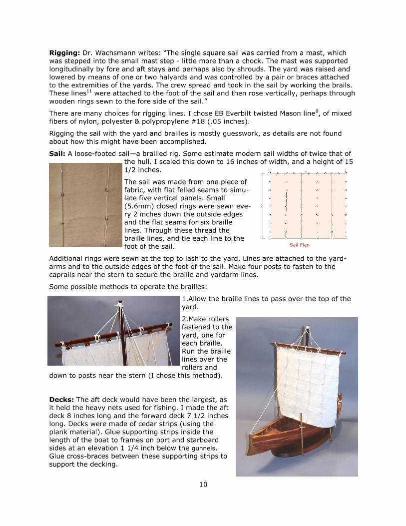
Sail: A loose-footed sail—a brailled rig. Some estimate modern sail widths of twice that of
the hull. I scaled this down to 16 inches of width, and a height of 15
1/2 inches.
The sail was made from one piece of
fabric, with flat felled seams to simu-
late five vertical panels. Small
(5.6mm) closed rings were sewn eve-
ry 2 inches down the outside edges
and the flat seams for six braille
lines. Through these thread the
braille lines, and tie each line to the
foot of the sail.
Additional rings were sewn at the top to lash to the yard. Lines are attached to the yard-
arms and to the outside edges of the foot of the sail. Make four posts to fasten to the
caprails near the stern to secure the braille and yardarm lines.
Some possible methods to operate the brailles:
1.Allow the braille lines to pass over the top of the
yard.
2.Make rollers
fastened to the
yard, one for
each braille.
Run the braille
lines over the
rollers and
down to posts near the stern (I chose this method).
Decks: The aft deck would have been the largest, as
it held the heavy nets used for fishing. I made the aft
deck 8 inches long and the forward deck 7 1/2 inches
long. Decks were made of cedar strips (using the
plank material). Glue supporting strips inside the
length of the boat to frames on port and starboard
sides at an elevation 1 1/4 inch below the gunnels.
Glue cross-braces between these supporting strips to
support the decking.
Sail Plan

11
Figures: The average man between the Hel-
lenistic and Byzantine period was estimated to
be 5’ 5” tall10. A simple tunic was the custom-
ary garment.
Wood figures 14
cm. high for the
men that match
the scale of the
boat were found
at Hobby Lobby
stores8and at
www.MadisonArtShop.com12.
The figures were painted, and the fuzz from a dog’s toy was
cut and glued, then painted for the hair of each figure.
Tunics for the figures were made of greige colored linen/cotton15. Tunics of the period
would have been made of either linen or wool (from sheep or camels).
Instructions to make tunics:
Cut out the pattern to cut fabric. Serge the front edge of 2 front pieces, and press under
the edge. Sew down with decorative stitch, and sew front to back at shoulder. Iron the
seam open and then to the back. Top stitch with decorative stitch. Turn under the sleeve
edge and stitch with decorative stitch right sides together. Sew side seam from sleeves
opening to bottom of hem. Iron seam open. Turn out the hem bottom edge. Make sash.
Display Stand:
I chose to make a cradle-like oval base of mahogany, 20 inches
long and 10 inches wide, and routed an ogee edge. Two vertical
supports 6 inches wide, 1 1/2 inch tall, and 9 inches apart are
shaped to the contour of the hull and keel, and mortised into the
base. Felt strips were glued over the top of the supports.
Thole Pins
Oars: Four oars, two on each side. Oars and rudder were turned on
a lathe to be 10 inches long and .35 inches in diameter, and the
blades shaped by carving and sanding. Oars are lashed to thole pins
on the gunnels. See Oars: Shaw & Tenney16.
Steering: Quarter rudders on each side of the boat were used to
steer. Constructed like the oars, with handles approximately .4 inch-
es
Removable Ceilings
Ceilings:
Glue cedar planks to oak or cedar cross-strips
(like the decking), shaped to lie loosely and flat
over the frames. These can be made in sections
on either side of the mast.
12
Finishing:
When all planks are in place, trim any uneven edges. Using the flat side of a sharp chisel,
trim exposed edges in the direction of the rising grain. Initial sanding can be done with 80
grit, finishing with about 180 to 220 grit.
If there are gaps between planks, they can be filled with slivers of cedar trimmed to glue in
the gaps. Very small gaps can be filled by inserting glue and filling with sawdust, or by us-
ing color-matched filler, such as Elmer’s Carpenters Wood Filler. Color-matched filler can
be made by mixing filler with sawdust from the planking material (test on scrap before ap-
plying to the hull). Apply one coat of finish before making repairs.
Tung oil is my choice for the finish. It permeates (polymerizes) the wood and dries to a
permanent and water-resistant finish that acquires a fine patina with time. The first two
coats can be brushed on and dried overnight. After a light sanding, subsequent coats can
be applied and wiped with a soft rag before becoming tacky. Allow each coat to dry over-
night. Three to four coats provide a durable finish. Add more coats if desired. This finish is
a good choice for all exterior and interior parts.
Apply finish to the interior of the hull before installing the two decks. Most of the area un-
der the decks will be unseen, but the finish is good protection.
When finishing the outside of the hull is complete, you may want to insert nails to simulate
the iron nails used to fasten planks to frames in the original boat. 3/8 inch long by .026
inch diameter brass nails are available from Micro-Mark11. Stick them in a sheet of polyure-
thane foam and spray-paint the heads black, then use a push hammer11 to insert nails
where planks join frames. Nail heads can be chemically darkened with gun blue. If you
have trouble inserting the nails, drill holes with a mini drill bit14 size #72 (.025 inch). If
wanting a uniform look, space nails the same distance apart.

13
Bibliography: 1Dr. Shelley Wachsmann, Meadows Professor of Biblical Archaeology, Nautical Archaeology
Program, Texas A&M University. 2The Sea of Galilee Boat, Dr. Shelley Wachsmann, Texas A&M University Press, 2009 3Scale drawings and details by Dr. J. Richard Steffy, 1924-2007, Nautical Archaeology
Program, Texas A&M University. 4Flavius Josephus, Wars of the Jews (c. 94), The Life of Flavius Josephus 5New Testament, Biblical references in the Gospels to events on the Sea of Galilee. There
are fifty references in the NT about activities regarding the Sea of Galilee. 10Page 317, The Sea of Galilee Boat2
Sources: 6Woodcraft, Sears, Lowes, Home Depot and other hardware stores. 7Glue choices are many. Titebond II or III are versatile and work well. If you might place
the model in water, user Titebond III. 8Hobby Lobby Stores. Cane skewer-type dowels come in all sizes. Measure before buying. 9Galilian Fishing Economy and the Jesus Tradition, by K. C. Hanson 10Page 317, The Sea of Galilee Boat2. 11Micro-Mark The Small Tool Specialists — Push Hammer for nails and Brass nails 3/8
inches long by .026 inches in diameter. 12Madison Art Shop www.MadisonArtShop.com
13Seaways’ Ships in Scale (Seaways Publishing, Inc., PO Box 525, Niwot, CO) 14Sloans Wood Shop, Lebanon, Tennessee. www.sloanswoodshop.com. 888-615-9663 for
#72 .025 drill bits. If needed, they also have a pin chuck for mini bits. 15Jewelry Supply.com at www.jewelrysupply.com
Additional reading: 9Galilian Fishing Economy and the Jesus Tradition, by K. C. Hanson
Fishing at the Time of Jesus, by Dr. Elizabeth McNamer, [email protected]
http://www.americancatholic.org/Newsletters/SFS/an0704.asp 15Making a simple tunic—http://www.riverbendcombat.com/tunic.html 16Oars: Shaw & Tenney, http://www.shawandtenney.com/wooden-rowing-oars.htm 17Steering Oars: The Case for the Steering Oar by Gary Dierking
Ancient Harbors of the Sea of Galilee, by Gordon Franz,
http://ldolphin.org/ancientharbors.html
Dick Webber
Edmond, Oklahoma

14
Ackn
ow
ledg
em
ent: N
ote
s o
n th
e c
onstr
uction o
f th
e K
inne
ret b
oa
t
J.
Ric
hard
Ste
ffy In
stitu
te o
f N
autica
l A
rch
aeo
logy,
Te
xa
s A
&M
Un
ive
rsity,
P.O
. D
raw
er
AU
, C
olle
ge
Sta
tion, T
exa
s 7
78
40, U
.S.A
.

15
Steam Bending Planks— other ideas:
These are excerpts from an Internet blog by Rob Macks and others about model boat steam bending: - http://shipmodeling.net/forum/archives/How_do_I_bend_wood_for_a_ship_model.html
For some places where I need a plank bent edge-wise (e.g., railings), I find it easier to take a WIDE piece of stock whose thickness is the final width, and bend this piece to shape. I then saw curved planks from the edge.
Use a (.5in or .75in dia) copper pipe to contain the plank strips and run live steam from a kettle through the pipe. Pin planks to hull formers until dry then glue. {Peng F. Mok}
I would guess that any bending technique can be applied in this manner: First sheer, and then the
other way. If you use steam, the whole plank will become wet and flexible - pin it in place while it dries and it should fit pretty well when it dries! The important thing is to make the plank fit naturally in place, so the pins and glue don't have to force it to keep in place!
You will need a pack of wooden clothes pins, the sort that has the tension spring in the middle. On
the profile of the gripping end, cut a piece out about half way up the profile so you have an 'L' shape. Inside the gripping end glue a piece of 240 wet & dry abrasive paper with contact adhesive. On the
inside of the squeezing end, glue some more 240 and make a timber wedge to fit. Around the spring, wrap some string to stop the peg separating. It doesn't have to be too tight - just enough to stop too much spread. Once one has steamed the plank, clamp it to the frames with the pegs. The long piece of peg slides over the frame and the shoulder holds the plank in place. The 240 offers enough friction to inhibit the pin sliding off the frame. Just to make sure the pin doesn't slide off, bang the wedge in the gripping end to separate it a bit.
You can't use PVA glue to glue up wet wood, which your plank will be after steaming so leave it to
take the shape of the hull and to get it dry before gluing up. A hair dryer will help accelerate the dry-ing process.
Soaking Method and soldering iron:
Cut the bow and stern taper in 4 planks, leaving them about 4 inches (2 on each end) longer than they need to be on the hull. You use the extra to give you something to hold onto while you bend
them and install them. Cut them in pairs, one for each side of the hull.
Float them in a soaking tray, (a piece of 4" or 6" pvc capped on both ends, then cut longitudinally in
half works well for this) for about a half hour. Flip the planks over and soak for about 15 minutes more. Pay attention to which planks form a pair. Plain, warm water works fine.
While you're waiting, cut two more planks and set them aside, clamp the soldering iron in a bench vice (by the handle) so its sticking straight up, and plug it in to heat.
Between installing the first and second planks, put two more into the soaking tray, and cut two more and set them aside. Installing two planks, while two planks are new in the soak tray, seems to work
well relative to the timing of the soak. You should have 4 in the tray all the time you're working.
I've been using a cryo based glue (Krazy glue) as my working glue, and it doesn't seem to care if there is still a little moisture in the wood. A day later, I reinforce the joints between the bulkheads and planks with carpenters (Elmer's yellow) for as many strakes as I can reach before the sides meet the deck. I also 'nail' my hulls though, so that may also be helping to hold them together. Keep re-
peating the process from step 4 until you get bored or tired. Then call it quits. When you do, clamp the keel into a keel clamp to make sure it doesn't bend while the wood finishes drying.
Note: The important message here is work one plank on each side of the hull at a time, even if you're doing the second layer of a double planked hull. Once the planks are fastened to the bulk-heads or inner hull, their environment is different from wherever you were storing them. They change shape and try to straighten back out. Wood is an imperfect medium, so you can't control the shape change. Working port, then starboard, with the help of a keel clamp, tends to average the stresses out by the time you reach the gunnels. You can hide a slightly bent keel, when the distor-tion is side to side, when you mount the model, but if you hog the hull, there's no way to hide it.

16
17

18

19

20

21

22


