457
P ETROLEUM G AS P ROCESSING (CHEM 433) ZIN EDDINE DADACH 1

PETROLEUM GAS PROCESSING
(CHEM 433)
ZIN EDDINE DADACH
1
COURSE INTRODUCTION
This course is designed to cover the fundamentals of the gas process operations in the petroleum industry
An overview of gas processing from exploration to final production and transportation as well as gas properties calculations are included.
2
COURSE FOCUS
The course focuses on the principles of
Natural Gas Liquids (NGL)* extraction
Liquid Petroleum Gas (LPG)** fractioning
Liquid Natural Gas production (LNG)
Some design aspects of major unit process operation.
3

FUNDAMENTALS
To understand this course, knowledge of the basic fundamentals principals and terminology a plus.
Review of basic terminologies follows:
4

BASIC TERMINOLOGY (QUICK
REVIEW)
Matter is the physical material that makes up the universe; anything that has mass and occupies space.
Elements, Atoms, Molecules, Chemical compounds, and Mixtures.
5

ELEMENT
A chemical element, or an element, is a material which cannot be broken down or changed into another substance using chemical means.
Elements may be thought of as the basic chemical building blocks of matter.
Depending on how much evidence you require to prove a new element has been created, there are 117 or 118 known elements.
6

ATOM
All substances are made up of matter and the fundamental unit of matter is the atom. The atom constitutes the smallest particle of an element which can take part in chemical reactions and may or may not exist independently.
N. Bohr (1940) provided the modern concept of the atomic model. According to Bohr, the atom is made of a central nucleus containing protons (positively-charged) and neutrons (with no charge). The electrons (negatively-charged) revolve around the nucleus in different imaginary paths called orbits or shells.
7
Valence shell: the outer most electron shell of an atom
Valence electron: an electron in the outermost shell (very important because these are the electrons that causes chemical reactions to occur.
They are represented by the group number in the periodic table.
8
BASIC TERMINOLOGY (QUICK
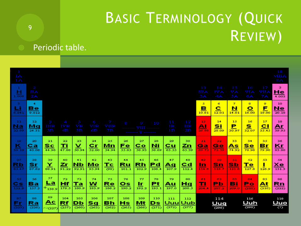
REVIEW) Periodic table.
9
BASIC TERMINOLOGY (QUICK
REVIEW)
Atomic Mass (weight): mass of 1 mole of an atom (listed in the periodic table)
e.g. the atomic mass of Al = 27g/mole (or 27g/gmole)
1 mole contains 6.0022 x 10 23 atoms
For Aluminum (Al) this means 27 g of aluminum contains 6.0022 x 10 23 atoms of aluminum *
In other words 6.0022 x 10 23 atoms of Al weighs 27g (**question, why not use the weight of 1 atom of aluminum in the periodic table?)
10

MOLECULE
Two or more atoms chemically combined.
Diatomic molecule: is a molecule that is formed by a combination of 2 atoms of the same element, e.g. N2, O2, H2.
11
H-H
H-H
H-H
H-H
H-H
H-H
H-H
Compound
Diatomic molecule

BASIC TERMINOLOGY (QUICK
REVIEW)
Going back:
Atomic Mass (weight) is the mass of 1 mole of an atom
E.g. The atomic weight of Al is 27 g/g-mole (this is from the periodic table)
Molecular Mass (weight) is the mass of 1
mole of ? *
E.g. The molecular weight of H2O is? **
12

PHYSICAL COMPOUNDS
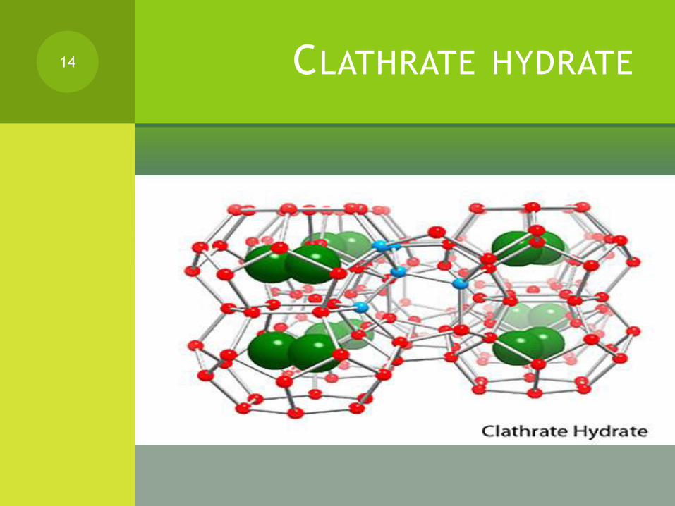
Clathrate, is a chemical substance consisting of a lattice of one type of molecule trapping and containing a second type of molecule
A type of physical compound, called a clathrate, may be formed. A gas hydrate is one example of a clathrate. These compounds are relatively unstable
An example of a clathrate is clathratehydrate, a special type of gas hydrate* in which a lattice of water molecule encloses molecules of trapped gas.
13
CLATHRATE HYDRATE14
CHEMICAL COMPOUND
Hydro carbon: Any compound made of carbon and hydrogen atoms.
These atoms can combine in a number of ways to satisfy valence requirements.
For convenience, these are separated into families (or homologous) series, each of which is given a name.
Carbon atoms can link together to form “chains” or “rings”
Crude oil and natural gas mixtures consist primarily of “straight chain” hydrocarbon molecules, the bulk of which are PARAFFINS*.
15

1) PARAFFIN SERIES FORMULA: CNH2N+2
Hydrocarbons in this series are saturated compounds because all four bonds are connected either to another carbon atom or a hydrogen atom, with one such atom for each bond.
In Paraffin (CnH2n+2 ) the # of hydrogen atoms is 2 times the # of carbon atoms plus 2 more for the end of the chain.
Name of paraffin compounds end with an “ane”
16
CH4 C2H6 C3H8
PARAFFIN SERIES FORMULA:
CNH2N+2 (CONTINUED)
* Just note and recall that Paraffin hydrocarbons are the most stable because all valence bonds are fully satisfied as indicated by the single line linkage.
Most reactions involve the replacement of hydrogen atoms with other atoms; the carbon linkage remains stable.
Longer chain may be formed, however, the only ones normally identified by name contain ten or less carbons.
Just note that in referring to a given paraffin hydrocarbon, the abbreviation C3 for propane, C4 for butane, etc may be used but,
Statements like “propane plus fraction ( C3+) refer to a mixture
composed of propane and larger molecules.
17
PARAFFIN ISOMERS
When paraffin series molecule contains four or more carbon atoms there are different ways these ca be connected without affecting the formula
Compounds which have the same chemical formula but a different molecular structure are called isomers
They posses different physical and chemical properties.
18
2) OLEFIN OR ETHYLENE SERIES
(ALKENES) FORMULA: CNH2N
The olefin group of compounds is a simple straight chain series in which all the names end in –ene.
Ethylene (ethene) C2H4 is the simplest molecule in the series.
Hydrocarbon in this series combine easily with other atoms like chlorine and bromine, without the replacement of hydrogen atoms.
Since they are so reactive, they are called unsaturated hydrocarbons.
19

2) OLEFIN OR ETHYLENE SERIES
(ALKENES) FORMULA: CNH2N
(CONTINUED)
Unlike the paraffins, the maximum bonding capacity of the carbon atom is not fully satisfied by hydrogen or carbon atoms.
Two adjacent carbon atoms form a “temporary” bond (in the absence of other available atoms) to meet bonding requirements fixed by valence.
The structural formula for the olefins uses a double line to indicate the double carbon-carbon linkage, the most reactive point in the molecule.
With four or more carbons, isomers also may result from the position of the double bond.
20
3) ACETYLENIC OR ALKYNE
SERIES FORMULA CNH2N - 2
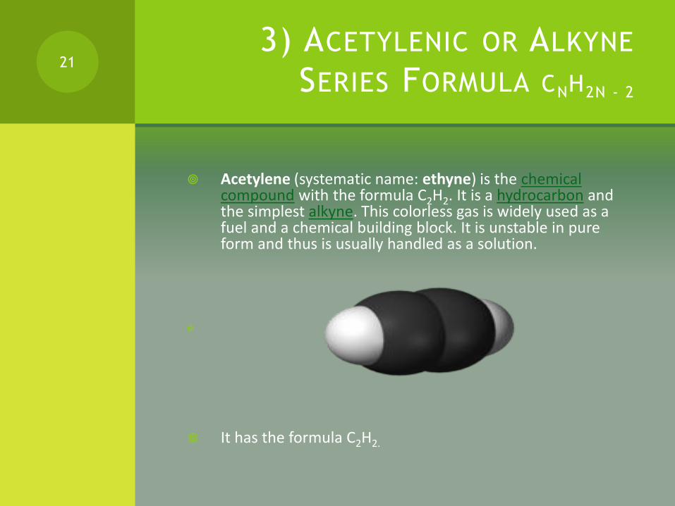
Acetylene (systematic name: ethyne) is the chemical compound with the formula C2H2. It is a hydrocarbon and the simplest alkyne. This colorless gas is widely used as a fuel and a chemical building block. It is unstable in pure form and thus is usually handled as a solution.
It has the formula C2H2.
21

3) ACETYLENIC OR ALKYNE
SERIES FORMULA CNH2N – 2
(CONTINUED) There is a triple bond between the carbon
atoms.
This satisfies the valence requirements but the carbon linkage is very weak.
Therefore Acetylene is even more reactive than olefins.
Acetylene not only is unsaturated, it is also unstable chemically.
In the liquid state is explosive if subjected to a sudden shock
22
4) DIOLEFINS FORMULA CNH2N - 2
Same formula as acetylene but contain two double linkages.
Di-ethene or di-butene
23

ORIGIN OF GAS AND OIL
24

THE ORIGIN OF PETROLEUM GAS
The organic theory: According to the original theory, oil originates
from animals and plants.
Beds of silt (containing tiny organisms), mud, and sand were buried deep beneath the earth.
The deepest layers were turned into rock by the weight of the deposited earth layers.
Geologists believe that high heat and pressure, bacteria, chemical reactions, and other forces transformed the organic remains into oil and gas.
25
The Inorganic Theory:
Hydrocarbons are formed by combination of carbon and hydrogen in the earth rocks due to the influence of high temperature and pressure
26

GEOLOGICAL CONDITIONS FOR OIL
AND GAS FORMATION
Most oil and gas accumulates in sedimentary rocks.
*Sedimentary rocks are one of three main rock groups (the others are igneous and metamorphic)
Sedimentary rocks include common types such as chalk, limestone, dolomite, sandstone, conglomerate and shale.
27

SEDIMENTARY ROCK IMAGES
(CHALK) 28

SEDIMENTARY ROCK IMAGES
(LIMESTONE)29

SEDIMENTARY ROCK IMAGES
(DOLOMITE)30

SEDIMENTARY ROCK IMAGES
(SANDSTONE)31

SEDIMENTARY ROCK IMAGES
(CONGLOMERATE )32

SEDIMENTARY ROCK IMAGES
(SHALE )33

GEOLOGICAL CONDITIONS FOR OIL
AND GAS FORMATION (CONTINUED)
Many people think that an oil or gas reservoir is a large underground container filled with oil or gas
Some people think its like an underground river.
In reality a petroleum or gas reservoirs is a rock formation that holds oil and gas, somehow like a sponge holding water.
Physically a large reservoir can be wide and shallow, narrow and deep or somewhere in between.
34
RESERVOIR ROCKS
A petroleum reservoir, or oil and gas reservoir, is a subsurface pool of hydrocarbons contained in porous or fractured rock formations. The naturally occurring hydrocarbons, such as crude oil or natural gas, are trapped by overlying rock formations with lower permeability. Reservoirs are found using hydrocarbon explorationmethods.
Porosity and permeability are important factors in reservoir formation. (QESTION) what's the difference between porosity and permeability? (next slide)
35

STRUCTURAL TRAPS
Structural traps are formed by a deformation in the rock layer that contains the hydrocarbons. Domes, anticlines, and folds are common structures. Fault-related features also may be classified as structural traps if closure is present.
Structural traps are the easiest to locate by surface and subsurface geological and geophysical studies.
They are the most numerous among traps and have received a greater amount of attention in the search for oil than all other types of traps.
36

STRUCTURAL TRAP ( FOLD)37

STRUCTURAL TRAP (FAULT)38

STRATIGRAPHIC TRAPS
Stratigraphic traps are formed when other beds seal a reservoir bed or when the permeabilitychanges (facies change) within the reservoir bed itself. Stratigraphic traps can form against either younger or older time surfaces.
39
POROSITY AND PERMEABILITY
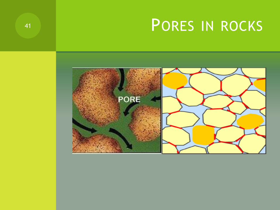
Porosity is the ratio of the volume of opening (voids) to the total volume of material. (e.g. Shale is less porous and carbonate is more porous)
Permeability is a measure of the ease with fluids will flow through rock, sediment or soil ( a rock is permeable when the pores are connected)
Just as with porosity, the packing, shape, and sorting of granular materials control their permeability. Although a rock may be highly porous, if the voids are not interconnected, then fluids within the closed, isolated pores cannot move.
40
PORES IN ROCKS41

POROSITY AND PERMEABILITY
(CONTINUED)
REAL ROCK IMAGE
42
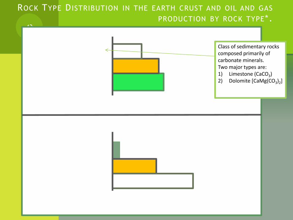
ROCK TYPE D ISTRIBUTION IN THE EARTH CRUST AND OIL AND GAS
PRODUCTION BY ROCK TYPE*.43
Carbonates
Sandstone
Shale
Distribution of rock types
42%
37%
21%
Sandstone
Carbonates (more
pores) *
Miscellaneous
Production by rock types
61.5%
36%
2.5%
Class of sedimentary rocks composed primarily of carbonate minerals.Two major types are:1) Limestone (CaCO3)2) Dolomite [CaMg(CO3)2]
RESERVOIR ROCKS (EROSION AND
DEFORMATION)
For a rock to be an effective reservoir, it must contain adequate porosity and permeability that is properly sealed against erosion and tectonic (movement) destruction.
Many reservoirs and traps have been generated and eliminated by erosion and deformation. They are called dead oil.
44
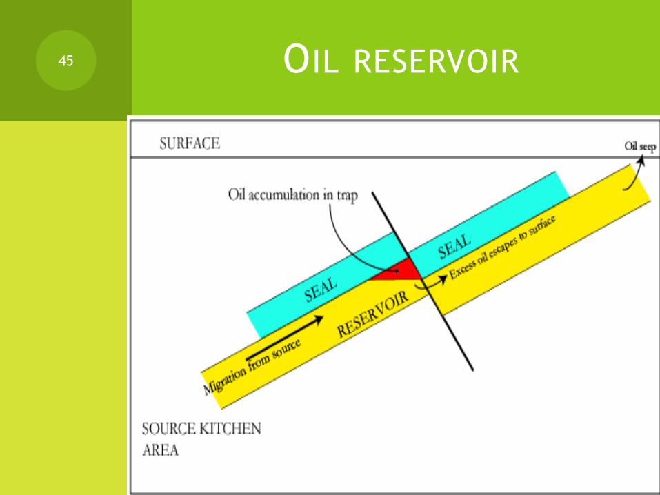
OIL RESERVOIR45

GENERATION OF CRUDE OIL
Organic material in shale averages approximately 1% of the shale rock volume. Clay mineral constituents comprise the remaining 99 percent
(some shale has greater concentrations some lower)
Kerogen* is an insoluble, high molecular weight, polymeric (i.e. consisting of a polymer) compound which comprises about 90% of the organic material in shale/rock.
The remaining 10% is bitumen** of varying composition, which is believed to be altered kerogen.
(See diagram next slide)
46

GENERATION OF CRUDE OIL (CONTINUED)47
Mineral Material 99%
Shale (rock)
Organic Material 1%
Kerogen 90%
Organic Material
Bitumens 10%
Percentage of (mineral and organic material), and (bitumen and
kerogen), and (mineral material) in rock
KEROGEN AND KEROGEN
TYPES
Labile kerogen breaks down to form heavy hydrocarbons (i.e. oils), refractory kerogen breaks down to form light hydrocarbons (i.e. gases) and inert kerogen forms graphite.
A Van Krevelen diagram is one example of classifying kerogens, where they tend to form groups when the ratios of hydrogen to carbon and oxygen to carbon are compared.
48

KEROGEN TYPE 1&2
Type I
Hydrogen:Carbon ratio > 1.25
Oxygen:Carbon ratio < 0.15
Tend to produce oil.
Type II
Hydrogen:Carbon ratio < 1.25
Oxygen:Carbon ratio 0.03 to 0.18
Tend to produce a mix of gas and oil.
49
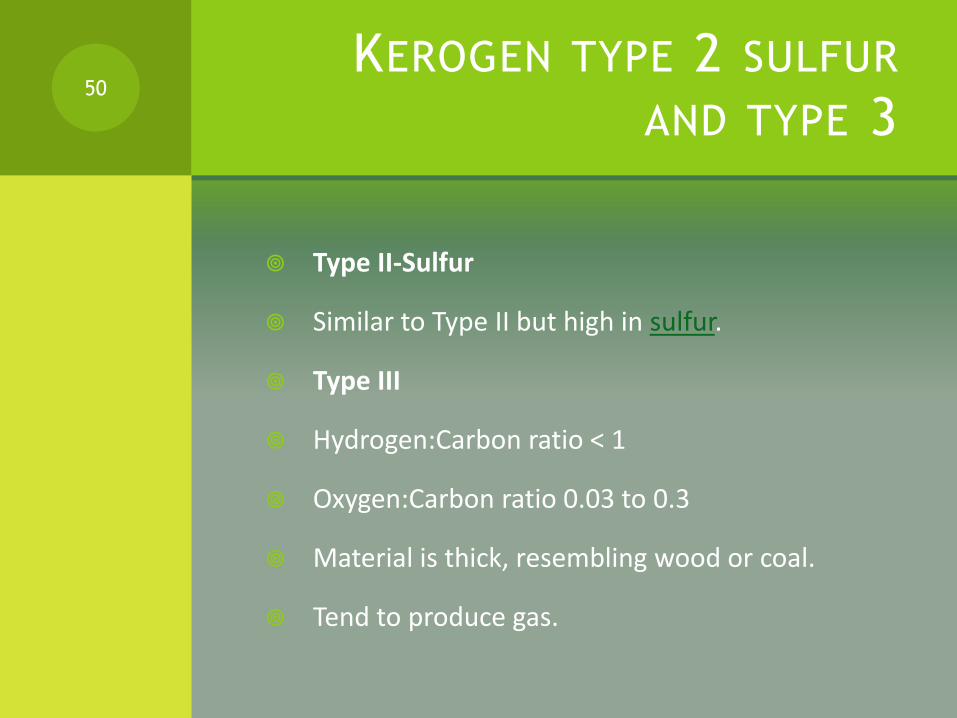
KEROGEN TYPE 2 SULFUR
AND TYPE 3
Type II-Sulfur
Similar to Type II but high in sulfur.
Type III
Hydrogen:Carbon ratio < 1
Oxygen:Carbon ratio 0.03 to 0.3
Material is thick, resembling wood or coal.
Tend to produce gas.
50
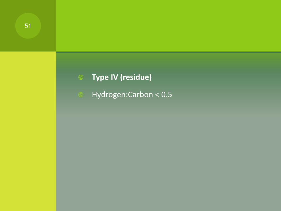
Type IV (residue)
Hydrogen:Carbon < 0.5
51
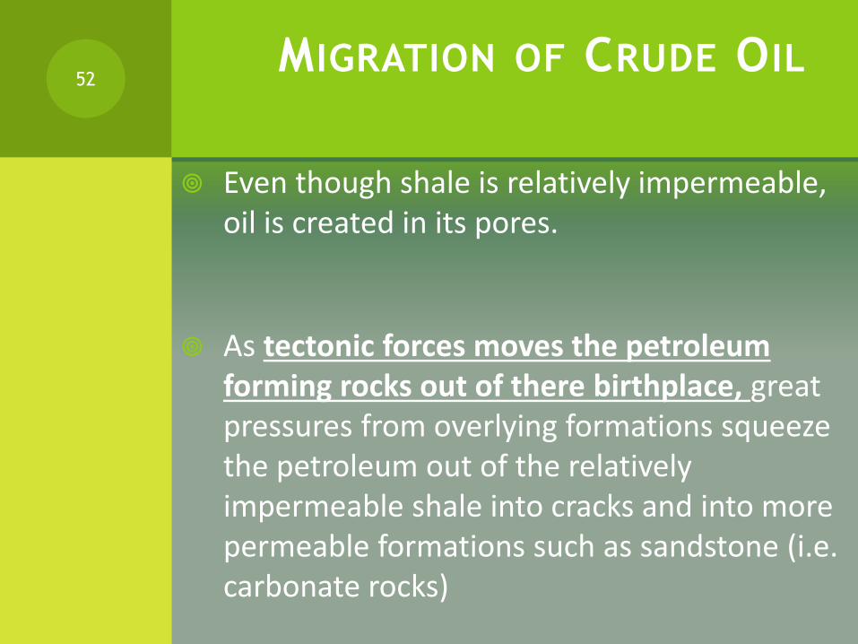
MIGRATION OF CRUDE OIL
Even though shale is relatively impermeable, oil is created in its pores.
As tectonic forces moves the petroleum forming rocks out of there birthplace, great pressures from overlying formations squeeze the petroleum out of the relatively impermeable shale into cracks and into more permeable formations such as sandstone (i.e. carbonate rocks)
52

SUMMARY (OIL MIGRATION) 53
Original OrganicMatter
Graphite
Kerogen
Mature Kerogen
Crude Oil
Methane
Losing Hydrogen Gaining Hydrogen
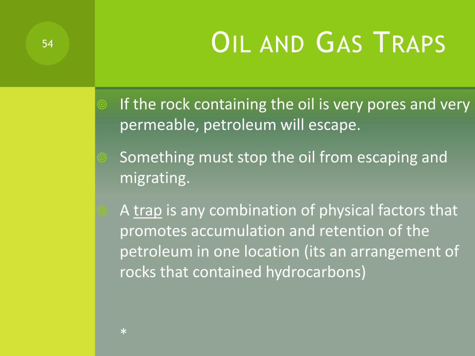
OIL AND GAS TRAPS
If the rock containing the oil is very pores and very permeable, petroleum will escape.
Something must stop the oil from escaping and migrating.
A trap is any combination of physical factors that promotes accumulation and retention of the petroleum in one location (its an arrangement of rocks that contained hydrocarbons)
*
54
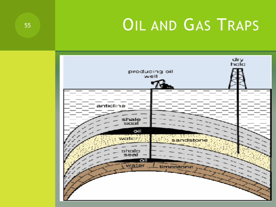
OIL AND GAS TRAPS55

CLASS WORK TO BE SUBMITTED
(USE THE INTERNET)
1. Traps can be grouped into three basic types? Name them.
2. How is an anticline trap formed?
3. What is a seal?
4. Scan or sketch figures showing common structural traps.
5. Sketch a dome trap showing the oil and water layers.
6. What is a plug trap is?
7. What causes a stratigraphic trap to form? Scan or sketch relevant figures.
56
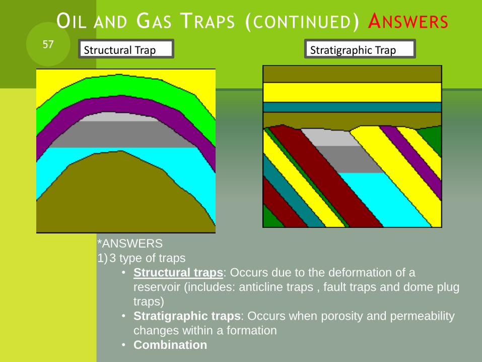
OIL AND GAS TRAPS (CONTINUED) ANSWERS57 Structural Trap Stratigraphic Trap
*ANSWERS
1)3 type of traps
• Structural traps: Occurs due to the deformation of a
reservoir (includes: anticline traps , fault traps and dome plug
traps)
• Stratigraphic traps: Occurs when porosity and permeability
changes within a formation
• Combination
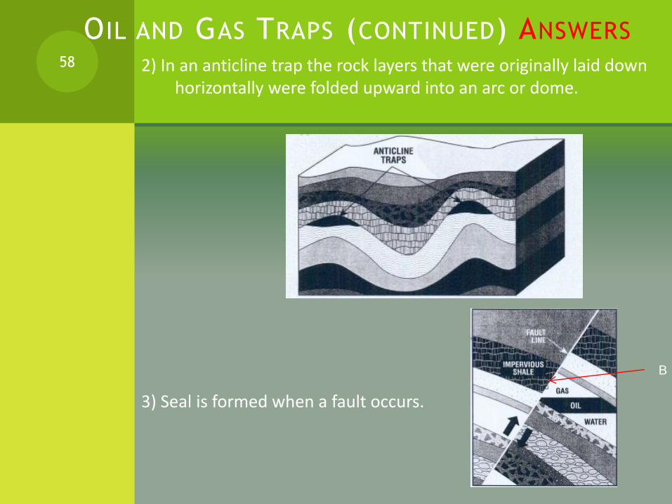
OIL AND GAS TRAPS (CONTINUED) ANSWERS
2) In an anticline trap the rock layers that were originally laid down horizontally were folded upward into an arc or dome.
3) Seal is formed when a fault occurs.
58
B
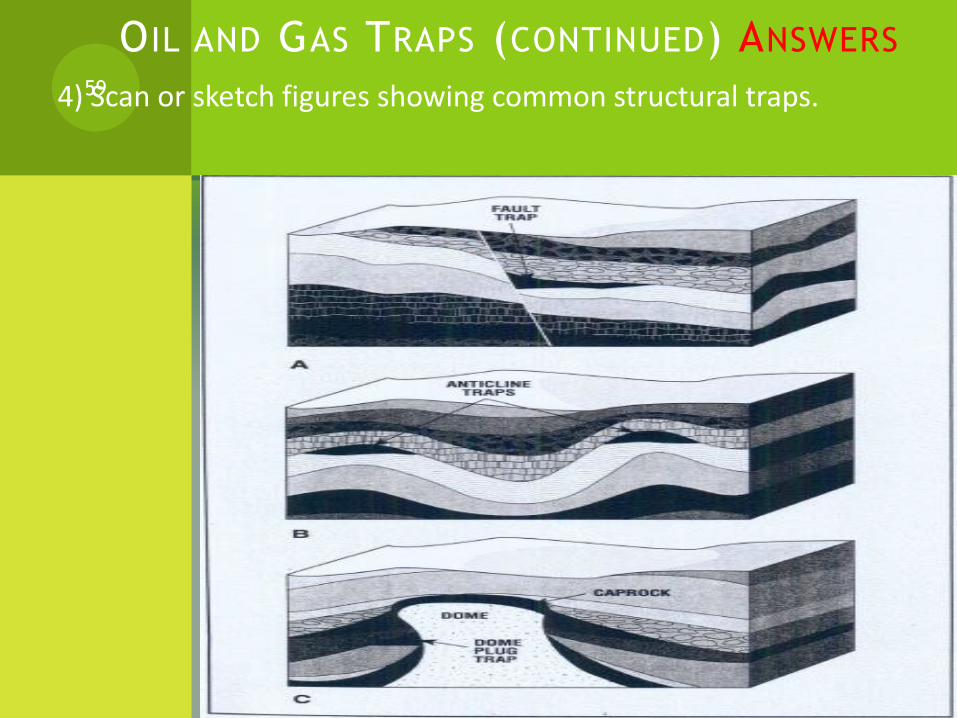
OIL AND GAS TRAPS (CONTINUED) ANSWERS
4) Scan or sketch figures showing common structural traps.59

O IL AND GAS TRAPS (CONTINUED) ANSWERS
5) A sketch of a dome trap showing the oil and water layers.60
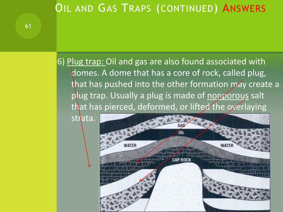
O IL AND GAS TRAPS (CONTINUED) ANSWERS
6) Plug trap: Oil and gas are also found associated with domes. A dome that has a core of rock, called plug, that has pushed into the other formation may create a plug trap. Usually a plug is made of nonporous salt that has pierced, deformed, or lifted the overlaying strata.
61

O IL AND GAS TRAPS (CONTINUED) ANSWERS
7) Stratigraphic trap is caused either by a nonporous formation sealing off the top edge of a reservoir bed or by a change of porosity and permeability within the reservoir bed itself.
62

EXPLORATION METHODS
63

EXPLORATION METHODS
Exploration was ones a matter of good luck and guess work
Now it uses many techniques and scientific principles
Most successful method was to drill near and oil seeps* (where oil is actually present on the surface)
Today, surface and subsurface, study is the leading technology in discovering oil and gas.
Aerial and satellite images and other instrumentation are used to gather information that helps determine where to drill.
Then specialist examine the rock fragments and core samples brought up while drilling the well and running special tools into the hole to get more information about the formation and possible oil or gas traps.
64

EXPLORATION METHODS (CONTINUED)
Finally examining, correlating and interpreting the information and the data makes it possible for the oil companies to accurately locate structures that may contain hydrocarbon and if the hydrocarbons are worth exploiting.
65

EXPLORATION METHODS
SUMMARY
Exploration methods include:
1) Surface geological studies
2) Oil and gas seeps.
3) Geophysical surveys (e.g. seismic surveys)
4) Reservoir development tools
66

CLASS WORK
Surface geological studies include areal photographs and satellite images. List at least 2 types of equipment used to take images, and explain briefly what information each equipment gives.
1) Explain what oil and gas seeps are?
2) Geophysical surveys includes the use several methods listed below, briefly explain each method and list any sub methods.
Magnetic and electromagnetic surveys (list each one and explain)
Gravity surveys
Seismic surveys (VERY IMPORTANT)
3D seismic surveys
Explosive Methods
Modern land methods
Marine Seismic Methods.
67

CLASS EXERCISE (ANSWERS, D ISCUSSION AND EXPLANATION)
Answers:
1) 2 types of equipment used to take images:
LandSat:
Landsat satellites have mapped all the earth's land masses this is continuously done.
The purpose is to primarily map vegetation and observe long-term changes to the earths surface.
LandSat also carry sensors especially built for geological application
It provides visible, thermal, and infrared images of all land-masses and coastal areas.
Landsat data is then interpreted and enhanced
Explorationists can then buy the data.
Radar
Radar devices bounce high frequency radio waves off land features to a satellite or airplane.
Returned signals form a low-resolution relief map (map of a terrain- topography like)
It is useful in searching areas for potential oil-trapping structures at a glance (diagram on next page)
68
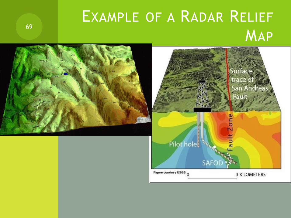
EXAMPLE OF A RADAR RELIEF
MAP69

OIL AND GAS SEEPS
Seeps are oil and gas that come to the surface along porous beds or faults. They are marked and well-documented worldwide.
70

CLASS EXERCISE (ANSWERS, D ISCUSSION AND EXPLANATION)
[CONTINUED]
2
71
Crude oil seep
Gas seep

CLASS EXERCISE (ANSWERS, D ISCUSSION AND EXPLANATION) [CONTINUED]
3) Geophysical surveys include:
Magnetic and electromagnetic surveys (list each one and explain):
Magnetometer surveys: detects slight variation in the earths magnetic field which results in predicting the characteristics of overlaying sediments.
Magnetotellurics: Works on the theory that rocks of different composition have different electrical properties. It measures the naturally occurring flow of electricity between rocks then reveals subsurface structures based on the electrical data.
72

GRAVITY SURVEYS
Gravity surveys (e.g. of an equipment used is gravimeter or gravity meter):
It works on the theory that some rocks are denser than others which causes a slight variation in the earth's gravitational field.
For example scientists can locate salt domes based on gravitational methods since salt domes are usually associated with minimum gravity compared, for example, with ordinary and anticline domes. (EXAMPLE ON NEXT SLIDE)
73

CLASS EXERCISE (ANSWERS, D ISCUSSION AND EXPLANATION) [CONTINUED]
74

Seismic surveys
Seismic exploration utilizes an acoustic (sound) source such as an artificial earthquake ( or dynamite explosion).
Acoustic waves travel through the formation and reflect back to a detector (called geophones) where travel time is measures.
The geophones send the signals to a recorder (called a seismograph) where the signals are magnified and a seismogram is produced.
*
75
Class exercise (Answers, Discussion and explanation) [Continued]
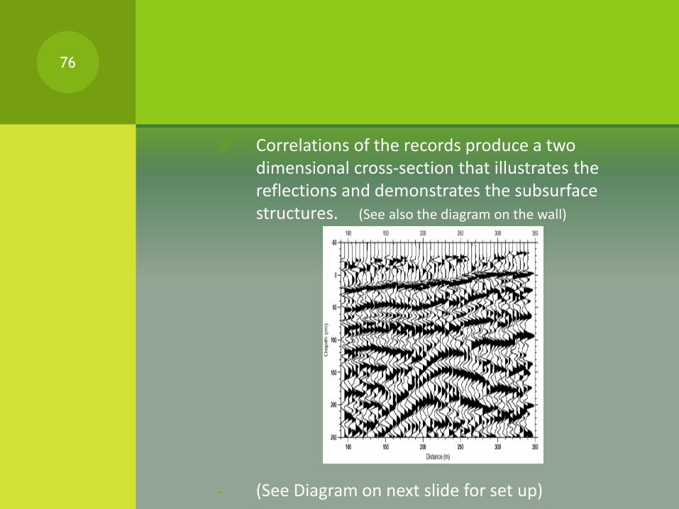
Correlations of the records produce a two dimensional cross-section that illustrates the reflections and demonstrates the subsurface structures. (See also the diagram on the wall)
- (See Diagram on next slide for set up)
76

Seismic surveys (continued) – Set-Up
Reflected and refracted seismic
Seismic exploration
77
Class exercise (Answers, Discussion and explanation) [Continued]
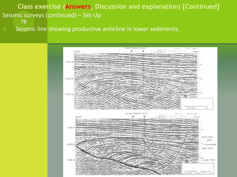
Seismic surveys (continued) – Set-Up
Seismic line showing productive anticline in lower sediments. 78
Class exercise (Answers, Discussion and explanation) [Continued]
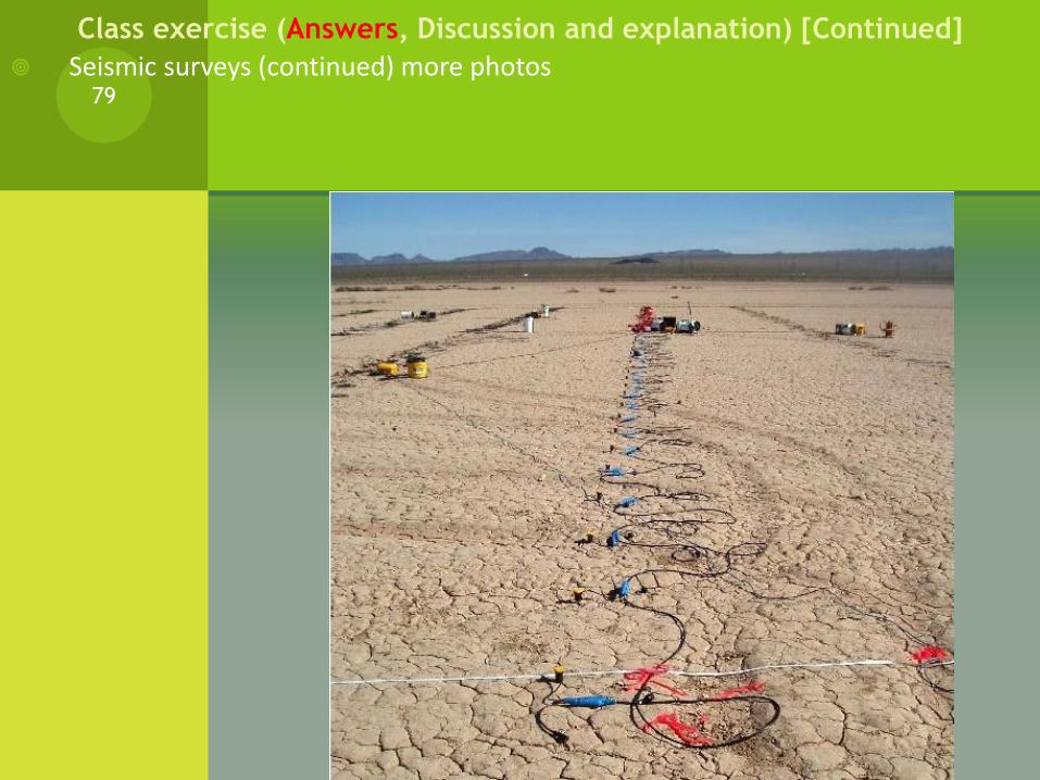
Seismic surveys (continued) more photos79
Class exercise (Answers, Discussion and explanation) [Continued]
CLASS EXERCISE (ANSWERS, D ISCUSSION AND EXPLANATION) [CONTINUED]
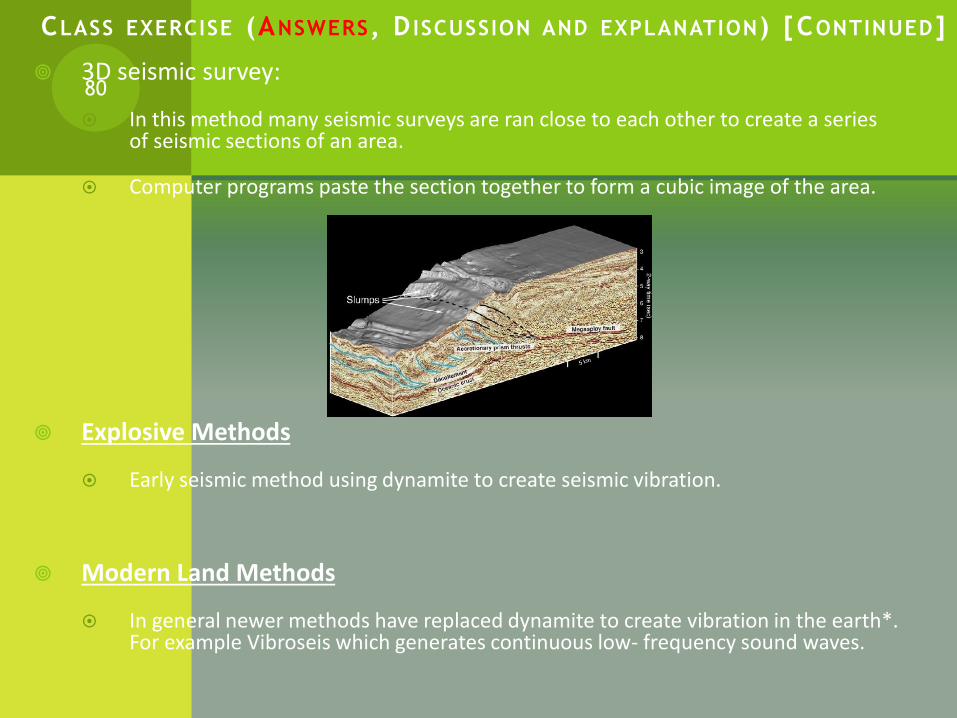
3D seismic survey:
In this method many seismic surveys are ran close to each other to create a series of seismic sections of an area.
Computer programs paste the section together to form a cubic image of the area.
Explosive Methods
Early seismic method using dynamite to create seismic vibration.
Modern Land Methods
In general newer methods have replaced dynamite to create vibration in the earth*. For example Vibroseis which generates continuous low- frequency sound waves.
80

CLASS EXERCISE (ANSWERS, D ISCUSSION AND EXPLANATION) [CONTINUED]
Marine Seismic Methods:
It uses similar equipment as exploration on land but uses it on a ship.
(End of exercise)
81

WELL LOGS AND SAMPLE LOGS
82

RESERVOIR DEVELOPMENT TOOLS
When a surface and subsurface information of a formation indicates a strong possibility of hydrocarbon existence, an oil company may then drill an exploratory well or wells
As the drilling progresses, underground rocks are then tested by means of core sampling and well logs.
The gathered data determines whether the reservoir has enough oil or gas to justify completing the exploration and then production.
83

RESERVOIR DEVELOPMENT TOOLS (CONTINUED)
Well logs are records that give information about the formation through which a well has been drilled.
The log gives the geophysical and other information of a well per depth.
84

TYPES OF WELL LOGS
1) Well Logs:
Driller’s log
Wireline log
2) Sample logs:
Core Samples
Cutting Sample
85

1) WELL LOGS
Driller log:
It’s the most common log where the log contains information about the kind of rocks and fluids encountered at different depths.
It gives also gives information when the formation is altered from soft to hard rock.
It gives an idea of how long it takes to drill the well (for future drilling purposes)
Gives other formation issues encountered during drilling.
86JPEG Image

1) WELL LOGS [CONTINUED]
Wireline logs:
A wireline is a metal cable (line) that run through the well hole with several tools attached to it.
Each tool takes a different measurement.
Each measurement gives an indirect information about the formation down the well.
Wireline logging often involves complex calculations and interpretations of the data provided from the tool.
Oil service companies (e.g. Schlumberger, Baker Atlas, Halliburton) uses the information to decide if the oil or gas in the well is economically feasible.
87

1) WELL LOGS [CONTINUED]
There are different types of wireline logs:
a) Electrical Logs
b) Nuclear Logs
c) Acoustic Logs
88
A) ELECTRICAL LOGS
*Induction Log: records conductivity (weak current) that flows naturally in the rocks. It gives an idea about the thickness and boundary of each layer in the borehole. (called spontaneous potential log i.e. SP log)
Resistivity Log: records resistance in the borehole (hydrocarbons do not conduct electricity while all waters do)
89
1) Well Logs [continued]
B) NUCLEAR LOGS
Gamma ray log:
measures radioactivity to determine what type of rocks are present in the well.
For example shale emits more radioactive elements than sandstone.
Neutron log:
The tool sends atomic particles (neutrons) through the formation.
When the neutrons collide with hydrogen, the hydrogen slows them down.
When the detector records slow neutrons, it means that there more hydrogen is present (i.e. maybe more hydrocarbons than water)
90
1) Well Logs [continued]
C) ACOUSTIC LOGS
It gives information about the density of the rocks (how dense the rock is)*
The acoustic or sonic log records how fast sound travels through a rock.*
The speed of sound traveled depends on how dense a formation is, and how much fluid it contains.
Example: shale is less porous therefore the sound will travel faster and you will get a high acoustic signal back. (E.g. of signal on the board)
91
1) Well Logs [continued]

C) ACOUSTIC LOGS (CONTINUED)
The probe contains a single transmitter at the base of the probe and two receivers located above the transmitter.
92
1) Well Logs [continued]

SAMPLE LOGS
Sample logs:
Core Samples
Cutting Sample
93

CORE SAMPLES
1) A core is a cylindrical column of rock that shows the sequence of rocks as they appear within the earth.
2) It provides the most accurate information about the underground formation about Porosity, permeability, composition, fluid content, and geological age.
94

CUTTING SAMPLES
As a regular bit drills a hole, it breaks up the rock into pieces called cuttings. The cuttings flow out of the hole where geologists can use them to analyze the rock being drilled.
Since cuttings are fragments of rocks and do not form a continuous sample like a core, they are not as useful cores are to the geologists.
Cuttings may not all come from the bottom of the hole but may include pieces of formations that have sloughed off closer to the surface.
Even with these limitations, however, cuttings can provide useful data and are regularly examined during drilling.
95

Homework by internet (10%) to be submitted February 27th
Based on the information of the handouts and using the internet, write a report about the oil and gas reservoirs:
a) How they are formed?
b) How they can be trapped?
c) The exploration techniques ( surface and sub-surface analysis)
d) The logs used to analyze them (drilling techniques)
e) Attach all the documents used.
96

THE DIFFERENT TYPES OF GASES
97
ASSOCIATED GAS
A mixture of petroleum gases that range from methane to butane and traces of liquid condensate (pentane to heptane)
It is produced from an oil well dissolved in the oil.
It is separated from the oil by liquid-gas separator in the degassing station.
The gas contains non-hydrocarbon gases such as CO2 and H2S as well as some water.
98

TYPICAL PROCESS OF AN
ASSOCIATED GAS99
NON-ASSOCIATED GAS
Gas occurring alone as natural gas, not in solution or as free gas with oil or condensate.
It contains mainly methane and ethane. It may also contains impurities such as CO2 , H2S and water
100
WET AND DRY GAS
Natural gas is often found dissolved in oil at the high pressures existing in a reservoir.
It can be present as a gas cap above the oil. Such natural gas is known as associated gas. There are also reservoirs that contain gas and no oil. This gas is termed non-associated gas.
Associated gas usually contains some light liquids and hence is sometimes called “wet gas.”
Non-associated gas, coming from reservoirs that are not connected with any known source of liquid petroleum, is “dry gas.”
101
SOUR AND ACID GAS
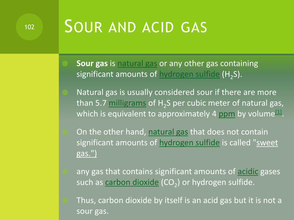
Sour gas is natural gas or any other gas containing significant amounts of hydrogen sulfide (H2S).
Natural gas is usually considered sour if there are more than 5.7 milligrams of H2S per cubic meter of natural gas, which is equivalent to approximately 4 ppm by volume[1].
On the other hand, natural gas that does not contain significant amounts of hydrogen sulfide is called "sweet gas.")
any gas that contains significant amounts of acidic gases such as carbon dioxide (CO2) or hydrogen sulfide.
Thus, carbon dioxide by itself is an acid gas but it is not a sour gas.
102
GAS SWEETENING
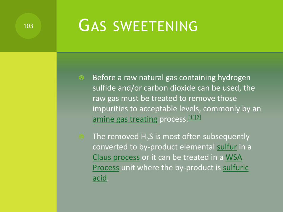
Before a raw natural gas containing hydrogen sulfide and/or carbon dioxide can be used, the raw gas must be treated to remove those impurities to acceptable levels, commonly by an amine gas treating process.[1][2]
The removed H2S is most often subsequently converted to by-product elemental sulfur in a Claus process or it can be treated in a WSA Process unit where the by-product is sulfuric acid.
103
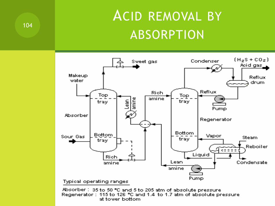
ACID REMOVAL BY
ABSORPTION104

LNG, LPG AND NGL
105

WHAT IS LNG?
Liquefied natural gas, or LNG, is natural gas that has been supercooled to minus 260 degrees Fahrenheit (minus 162 degrees Celsius).
At that temperature, natural gas condenses into a liquid. When in liquid form, natural gas takes up to 600 times less space than in its gaseous state, which makes it feasible to transport over long distances.
In the form of LNG, natural gas can be shipped from the parts of the world where it is abundant to where it is in demand.
106
LNG is an energy source that has much lower air emissions than other fossil fuels, such as oil or coal.
LNG is odorless, colorless, non-corrosive and non-toxic. Its weight is less than one-half that of water.
Natural gas is the world’s cleanest burning fossil fuel and it has emerged as the environmentally preferred fuel of choice.
107

NATURAL GAS COMPOSITION
The primary component of natural gas is methane (CH4), the shortest and lightest hydrocarbon molecule.
Natural gas as a fossil fuel also contains heavier gaseous hydrocarbons such as ethane (C2H6), propane (C3H8) and butane (C4H10), as well as carbon dioxide and sulfur-containing gases in varying amounts.
Fossil natural gas also contains in varying amounts and is the primary market source of helium, a non-renewable and valuable resource.
108

NATURAL GAS COMPOSITION
Methane (CH4) 80-95 %
Ethane (C2H6) 5-15 %
Propane (C3H8) and Butane (C4H10) < 5 %
109
HEATING VALUE
Natural gas is mainly used as a combustible
Quantities of natural gas are measured in normal cubic meters (corresponding to 0 °C at 1 atm) or in standard cubic feet (corresponding to 60 °F and 30 inches mercury).
The gross heat of combustion of one normal cubic meter of commercial quality natural gas is around 39 megajoules (≈10.8 kilowatt-hours), but this can vary by several percent.
In U.S. units, one standard cubic foot of natural gas produces around 1,000 British Thermal Units (BTUs).
110

HEATING VALUE OF NATURAL GAS
The actual heating value when the water formed does not condense is the net heat of combustion and can be as much as 10 percent less.
In the United States, natural gas is often sold at retail in units of therms (th), where 1 therm = 100,000 BTU.
Wholesale transactions are generally done in decatherms (Dth), or thousand decatherms (MDth), or million decatherms (MMDth).
A million decatherms is roughly a billion cubic feet of natural gas.
111

WHAT IS LPG ?
Liquefied petroleum gas (also called LPG, GPL, LP Gas, or autogas) is a flammable mixture of hydrocarbon gasesused as a fuel in heating appliances and vehicles.
It is increasingly used as an aerosol propellant and a refrigerant, replacing chlorofluorocarbons in an effort to reduce damage to the ozone layer.
Varieties of LPG bought and sold include mixes that are primarily propane, mixes that are primarily butane, and -most common - mixes including both propane C3H8 and butane C4H10, depending on the season — in winter more propane, in summer more butane
112
Propylene and butylenes are usually also present in small concentration.
A powerful odorant, ethanethiol, is added so that leaks can be detected easily.
The international standard is EN 589. In the United States, thiophene or amyl mercaptan are also approved odorants.
Blended of pure, dry "isopropane" (refrigerant designator R-290a ) and isobutane (R-600a) have negligible ozone depletion potential and very low global warming potentialand can serve as a functional replacement for R-12, R-22, R-134a,and other chlorofluorocarbon or hydrofluorocarbon refrigerants in conventional stationary refrigeration and air conditioning systems.[4]
113

ENVIRONMENT
As a low-carbon, low-polluting fossil fuel, LPG is recognized by governments around the world for the contribution it can make towards improved indoor and outdoor air quality and reduced greenhouse gas emissions
114
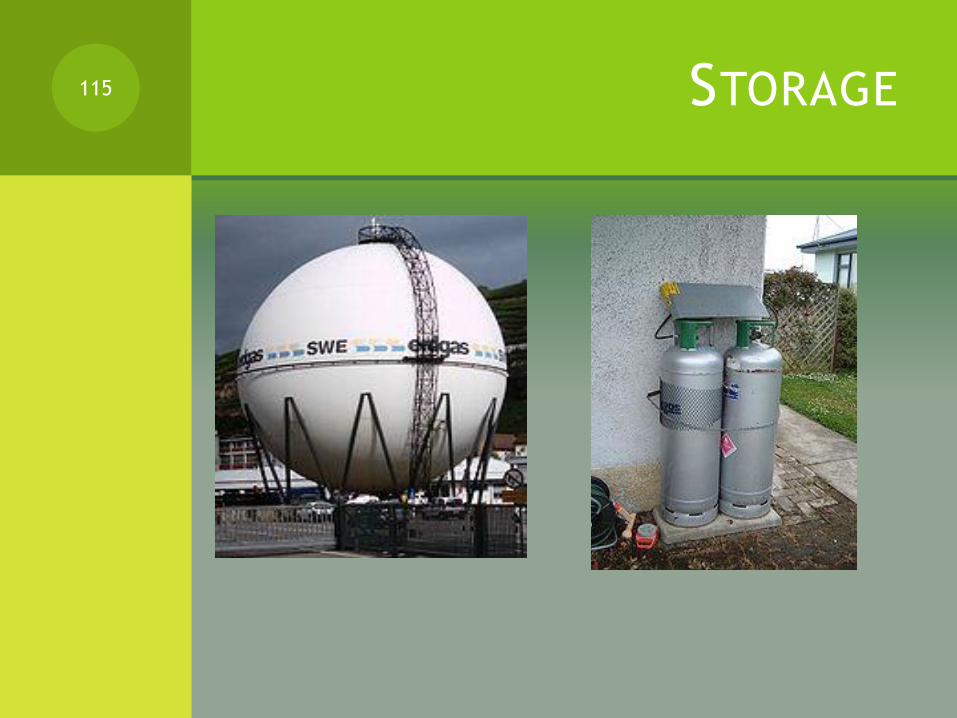
STORAGE115
WHAT IS NGL?
Natural Gas, the source of Natural Gas Liquids is a natural mixture of gaseous hydrocarbons found in the ground or obtained from specially driven wells.
The composition of natural gas varies in different parts of the world. Its chief component, methane, usually makes up from 80% to 95% its composition.
The balance is composed of varying amounts of ethane, propane, butane, and other liquid hydrocarbon compounds.
They include Ethane, Propane, Butanes (Iso and Normal), and condensate, all of which can be extracted from gas plants. Propane and Butanes can also be extracted during Crude Oil refining.
116

Normal Butane is a refining blend stock for gasoline and is also used as a Petrochemical feedstock,
Iso-Butane is a refining feedstock for alkylation, MTBE & TAME manufacturing and a component of gasoline octane blends.
117
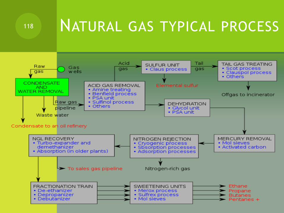
NATURAL GAS TYPICAL PROCESS118
CALCULATING THE DIFFERENT
PROPERTIES OF GASES.
119
GAS COMPOSITION BY
CHROMATOGRAPHY
Chromatography involves a sample being dissolved in a mobile phase (which may be a gas, a liquid or a supercritical fluid).
The mobile phase is then forced through an immobile, immiscible stationary phase.
The phases are chosen such that components of the sample have differing solubilities in each phase.
A component which is quite soluble in the stationary phase will take longer to travel through it than a component which is not very soluble in the stationary phase but very soluble in the mobile phase.
120

PHYSICAL PROPERTIES OF
NATURAL GAS.
I) COMPOSITION BY GAS CHROMATOGRAPHY:
As a result of these differences in mobilities, sample components will become separated from each other as they travel through the stationary phase.
Typical composition of natural gas:
a) Methane (CH4) 70-90% WT
b) Ethane (C2H6) 5-15
c) Propane (C3H8) and Butane (C4H10) < 5
d) Nitrogen, helium, carbon dioxide and trace amounts of hydrogen sulfide, water and odorants can also be present.
121
OTHER COMPONENT
e) Natural gas also contains and is the primary market source of Mercury is also present in small amounts in natural gas extracted from some fields[3].
The exact composition of natural gas varies between gas fields.
122
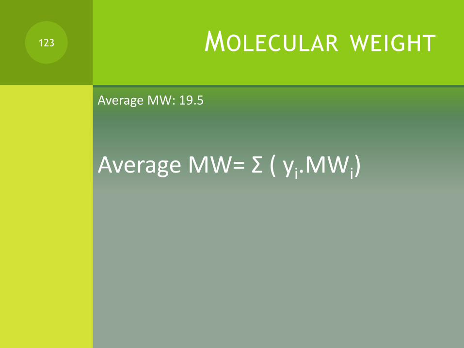
MOLECULAR WEIGHT
Average MW: 19.5
Average MW= Σ ( yi.MWi)
123

DENSITY OF NATURAL GAS
Average density (kg/m3): 0.7 - 0.9
Average density ( lb/ft3): 0.044 - 0.056
The density of gases depends on the compressibility factor
ρ= P.MW/z.R.T
For ideal gases ( low pressures below 10 atm and high temperatures)
ρ= P.MW/R.T
124

LISTEN...LEARN....THINK...ENJOY YOURSELF
EQUATIONS OF STATE FOR
REAL GASES
The ideal-gas equation is very simple, but its range and applicability are limited.
Several equations of state have been proposed in the literature to describe the behavior of real gases
We will discuss :
Van der Waals equation
Beattie- Bridgeman equation
LISTEN...LEARN....THINK...ENJOY YOURSELF
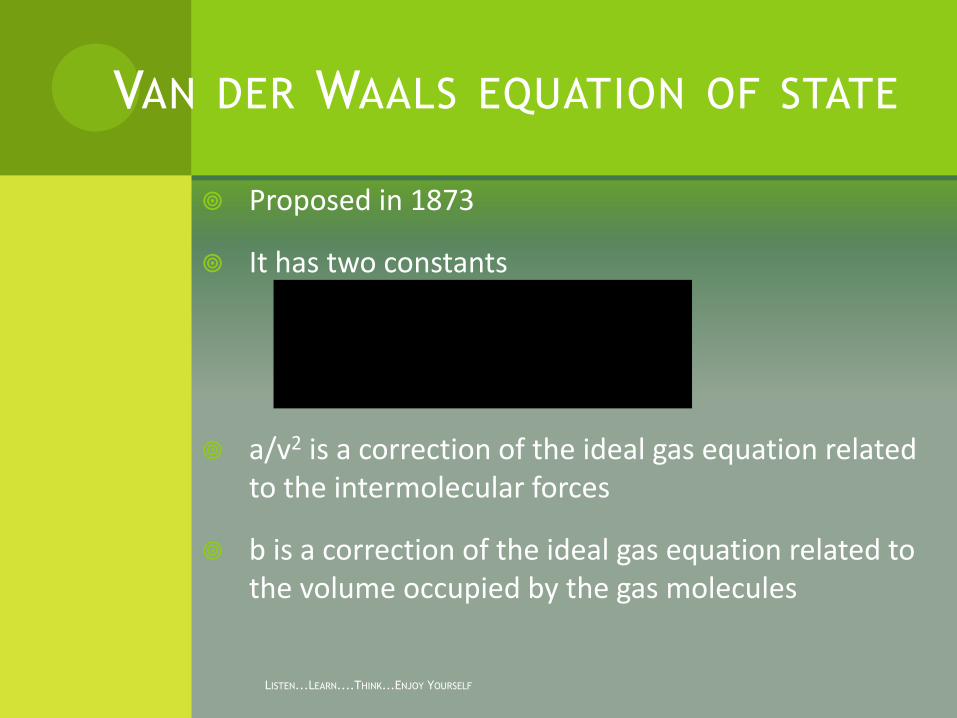
VAN DER WAALS EQUATION OF STATE
Proposed in 1873
It has two constants
a/v2 is a correction of the ideal gas equation related to the intermolecular forces
b is a correction of the ideal gas equation related to the volume occupied by the gas molecules
RTbvv
aP ))((
2

LISTEN...LEARN....THINK...ENJOY YOURSELF
DETERMINATION OF A AND B
cr
cr
P
TRa
64
27 22
cr
cr
P
RTb
8

LISTEN...LEARN....THINK...ENJOY YOURSELF
BEATTIE- BRIDGEMAN EQUATION
OF STATE
Proposed in 1928
It has five experimental constants
232
u
v
A)Bv)(
vT
c1(
v
TRP
)1(....).......1( 00v
bBBand
v
aAA

LISTEN...LEARN....THINK...ENJOY YOURSELF
WHAT CAUSES DEVIATION FROM
IDEAL GAS BEHAVIOR?
Intermolecular forces called Van Der Waals forces . There are three such types of Van Der Waals forces:
London Dispersion Forces which are forces that exist between molecules as a result of positive nuclei of one molecule attracting the electrons of another molecule..
Dipole-Dipole interactions which are forces that exist between polar molecules where the positive end of one molecule attracts the negative end of another molecule.
Hydrogen bonding interactions are forces that exist between molecules that have a hydrogen atom bonded to a highly electronegative atom such as Oxygen, Nitrogen, or Flourine.
LISTEN...LEARN....THINK...ENJOY YOURSELF
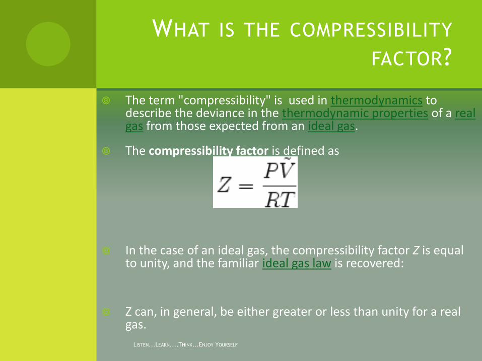
WHAT IS THE COMPRESSIBILITY
FACTOR?
The term "compressibility" is used in thermodynamics to describe the deviance in the thermodynamic properties of a real gas from those expected from an ideal gas.
The compressibility factor is defined as
In the case of an ideal gas, the compressibility factor Z is equal to unity, and the familiar ideal gas law is recovered:
Z can, in general, be either greater or less than unity for a real gas.

LISTEN...LEARN....THINK...ENJOY YOURSELF
REAL PHASE REGION
The deviation from ideal gas behavior tends to become particularly significant (or, equivalently, the compressibility factor stays far from unity) :
near the critical point,
in the case of high pressures
low temperatures.
In these cases, an alternative equation of statebetter suited to the problem.

LISTEN...LEARN....THINK...ENJOY YOURSELF
COMPRESSIBILITY
FACTOR
The compressibility factor can be estimated from figure 3-2 page 56 if we know the reduced temperature and the reduced pressure of the gas:
PR= P/PC and TR= T/TC
The compressibility factor Z is almost the same for all the gases at the same reduced pressure and reduced temperature . This is called the principle of corresponding states

PC AND TC : KAY’S RULE
Kay’s rule (Page 56):
Pc= Σ yi.Pci
Tc= Σyi.Tci
Tci and Pci from tables 3.1 and 3.2
Do example 3.1 page 57
133
NATURAL GAS CONTAINING
CO2 AND H2S
Two methods available:
1) Approach proposed by Robinson et al:
2) Approah proposed by Wichert and Aziz:
The second method uses adjustments of the Pc’ and Tc’ which is found from Kay’s combination rule. It has a correction factor ε, found from figure 3.3 page 58
134
CORRECTION FOR TC’
Tc”= Tc’-0.556 ε ( SI)
Tc”= Tc’- ε ( FPS)
135
CORRECTION IN PC’
Pc”= Pc’.Tc” / {(Tc’+0.556.B.ε.(1-B))} (SI)
Pc”= Pc’.Tc” / {(Tc’+B.ε.(1-B))} (FPS)
Pc’ and Tc’ from Kay’s rule
ε from figure 3.3
B mole fraction of H2S in gas
136
FIGURE 3.3 PAGE 58
Figure 3.3 can be estimated by the equation:
ε= 120 ( A0.9- A1.6) +15 (B0.5-B4)
ε= correction factor
A total mole fraction ( H2S +CO2) in the gas
B mole fraction CO2 in the gas.
137
FIGURE 3.3 PAGE 58
Figure 3.3 can be estimated by the equation:
ε= 120 ( A0.9- A1.6) +15 (B0.5-B4)
ε= correction factor
A total mole fraction ( H2S +CO2) in the gas
B mole fraction H2S in the gas.
Do example 3.2 page 59.
138

HEATING CONTENT OF LIGHT
HYDROCARBONS
139
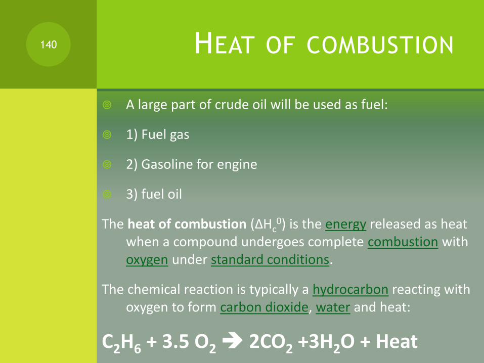
HEAT OF COMBUSTION
A large part of crude oil will be used as fuel:
1) Fuel gas
2) Gasoline for engine
3) fuel oil
The heat of combustion (ΔHc0) is the energy released as heat
when a compound undergoes complete combustion with oxygen under standard conditions.
The chemical reaction is typically a hydrocarbon reacting with oxygen to form carbon dioxide, water and heat:
C2H6 + 3.5 O2 2CO2 +3H2O + Heat
140
HEAT OF COMBUSTION
By measurement:
The heat of combustion is traditionally measured with a bomb calorimeter.
By calculation:
It may also be calculated as the difference between the heat of formation (ΔfH
0) of the products and reactants.
141

CALORIMETRY TO MEASURE HEAT
OF COMBUSTION OF METHANE
CH4 (g) + 2 O2 (g) → CO2 (g) + 2 H2O (l)
The enthalpy change for this reaction is measured by pressurizing a strong metal reaction vessel (called a bomb) with a mixture of methane and oxygen gas.
The bomb is immersed in a calorimeter filled with water. An electrical current is passed through ignition wire (a fine iron wire), which ignites the wire and the gas mixture.
The heat balance for this calorimetry experiment is:
0 = qcal + qwire + qcomb
142

The heat for the calorimeter, qcal, is determined from the heat capacity of the calorimeter and the temperature change for the calorimetry experiment.
Typically the amount of water in the calorimeter is always the same; therefore Ccal includes the heat capacities of the calorimeter, the water, and the bomb itself.
The burning of the ignition wire releases heat, qwire, and this heat must be included in the calculations. (This heat is treated separately, because the amount of ignition wire used varies from one measurement to the next.)
143

COMBUSTION EXPERIMENT
The heat released by the combustion reaction is qcomb, which is related to the molar enthalpy of combustion by
ΔHcomb = qcomb /nmethane Combustion experiments are general conducted with a large excess of oxygen, so that the fuel (methane in this case) is the limiting reactant.
144
MOLAR ENTHALPIES OF
FORMATION
Combustion reactions are often used to calculate the molar enthalpies of formation.
For example, the standard molar enthalpy of combustion for methane can be expressed in terms of the standard molar enthalpies of formation of the reactants and products:
ΔHocomb = 2 ΔHo
f,water + ΔHof,carbon dioxide - ΔHo
f,methane - 2 ΔHof,oxygen
ΔHocomb is measured experimentally.
ΔHof,oxygen = 0, because oxygen is a pure element.
The other molar enthalpies of formation are known from independent measurements.
145
For example, one could determine the heat of combustion of hydrogen to obtain the molar enthalpy of formation for water.
For liquid water, ΔHof = -285.8 kJ mole-1
For gaseous carbon dioxide, ΔHof = -393.5 kJ mole-1
146
HEATING VALUE=
HEAT OF COMBUSTION
The heating value or energy value of a substance, usually a fuel or food (see food energy), is the amount of heatreleased during the combustion of a specified amount of it.
The energy value is a characteristic for each substance. It is measured in units of energy per unit of the substance, usually mass, such as: kJ/kg, J/mol, kcal/kg, Btu/m³.
Heating value is commonly determined by use of a bomb calorimeter.
147

HIGHER HEATING VALUE
The quantity known as higher heating value (HHV) (or gross energy or upper heating value or gross calorific valueor higher calorific value HCV) is determined by bringing all the products of combustion back to the original pre-combustion temperature, and in particular condensing any vapor produced.
Such measurements often use a temperature of 25 °C. This is the same as the thermodynamic heat of combustion since the enthalpy change for the reaction assumes a common temperature of the compounds before and after combustion, in which case the water produced by combustion is liquid.
148
LOWER HEATING VALUE
The quantity known as lower heating value (LHV) (or net calorific value or lower calorific value LCV)) is determined by subtracting the heat of vaporization of the water vapor from the higher heating value.
This treats any H2O formed as a vapor. The energy required to vaporize the water therefore is not realized as heat.
LHV calculations assume that the water component of a combustion process is in vapor state at the end of combustion, as opposed to the higher heating value (HHV) (a.k.a. gross calorific value or gross CV) which that assumes all of the water in a combustion process is in a liquid state after a combustion process.
149

For hydrocarbons the difference between HHV and LHV depends on the hydrogen content of the fuel. For gasoline and diesel the higher heating value exceeds the lower heating value by about 10% and 7%, respectively, for natural gas about 11%.
A common method of relating HHV to LHV is:
HHV = LHV + hv x (nH2O,out/nfuel,in)
where hv is the heat of vaporization of water, nH2O,out is the moles of water vaporized and nfuel,in is the number of moles of fuel combusted.[1]
150
Most applications which burn fuel produce water vapor which is not used and thus wasting its heat content.
In such applications, the lower heating value is the applicable measure. This is particularly relevant for natural gas, whose high hydrogen content produces much water.
The gross energy value is relevant for gas burnt in condensing boilers and power plants with flue gas condensation which condense the water vapor produced by combustion, recovering heat which would otherwise be wasted.
151

SOME VALUES FOR LIGHT
HYDROCARBONS
Component HHV ( MJ/kg) LHV (MJ/kg)
hydrogen 141.8 121
Methane 55.50 50
Ethane 51.9 47.8
Propane 50.35 46.35
Butane 49.50 45.75
Pentane 45.35
gasoline 47.30 44.40
152
HEATING VALUE OF A
MIXTURE
GHV (HHV)= Σ( GHV)i.yi
Net heating value or LHV = Σ (LHV)i.yi
153
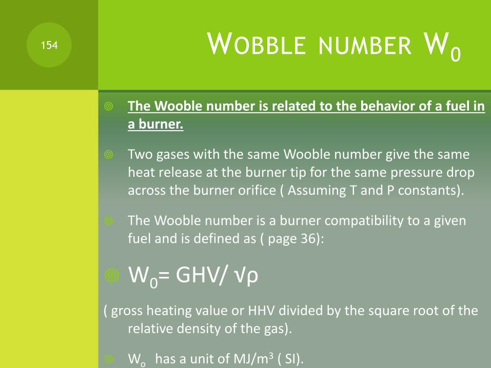
WOBBLE NUMBER W0
The Wooble number is related to the behavior of a fuel in a burner.
Two gases with the same Wooble number give the same heat release at the burner tip for the same pressure drop across the burner orifice ( Assuming T and P constants).
The Wooble number is a burner compatibility to a given fuel and is defined as ( page 36):
W0= GHV/ √ρ
( gross heating value or HHV divided by the square root of the relative density of the gas).
Wo has a unit of MJ/m3 ( SI).
154

SENSIBLE HEAT AND
ENTHALPY OF GASES
155

SENSIBLE HEAT
Sensible heat is calculated when there is temperature change with no change in phase.
We need the heat capacities Cp and Cv to estimate the enthalpy needed or released due to a change of temperature ∆T.
For an ideal gas, constant pressure process or a liquid:
∆h= ∫cp.dT
Cp= A+BT+CT2
156

SENSIBLE HEAT FOR GASES
In general Cp is a function of temperature but the calculation of Cp at the average temperature is often used, therefore
Tav= (T1+T2)/2
∆h=∫Cp(T).dT= Cp.av ( T2-T1)
157
FIG 8.3 FOR ESTIMATION OF
SPECIFIC HEAT FOR NATURAL GAS
For real gas:
∆h= ∫cp.dT+ ∫{V-T(δV/δT)p }dP
From fig 8.3 page 222.
Do example 8.2 page 222.
158

ENTHALPY OF GASES
Figures 8A.2 to 8.A14 pages 234-247.
For Gases MW=16-30
159
VISCOSITY OF GASES
160

IMPORTANCE OF VISCOSITY
Viscosity is another important property of a gas used primarily in flow calculations.
Viscosity describes a fluid's internal resistance to flow and may be thought of as a measure of fluid friction.
Viscosity is a measure of the resistance of a fluid which is being deformed by either shear stress or tensile stress.
In everyday terms (and for fluids only), viscosity is "thickness" or "internal friction". Thus, water is "thin", having a lower viscosity, while honey is "thick", having a higher viscosity.
Put simply, the less viscous the fluid is, the greater its ease of movement (fluidity).
161
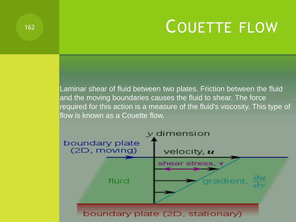
COUETTE FLOW162
Laminar shear of fluid between two plates. Friction between the fluid
and the moving boundaries causes the fluid to shear. The force
required for this action is a measure of the fluid's viscosity. This type of
flow is known as a Couette flow.

APPLIED FORCE –VISCOSITY
The applied force is proportional to the area and velocity gradient in the fluid and inversely proportional to the distance between the plates. Combining these three relations results in the equation:
F= μ.A.(u/y) where μ is the proportionality factor called viscosity.
163
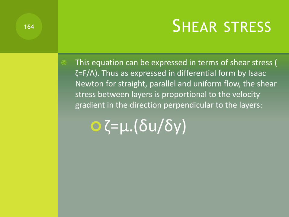
SHEAR STRESS
This equation can be expressed in terms of shear stress ( ζ=F/A). Thus as expressed in differential form by Isaac Newton for straight, parallel and uniform flow, the shear stress between layers is proportional to the velocity gradient in the direction perpendicular to the layers:
ζ=μ.(δu/δy)
164
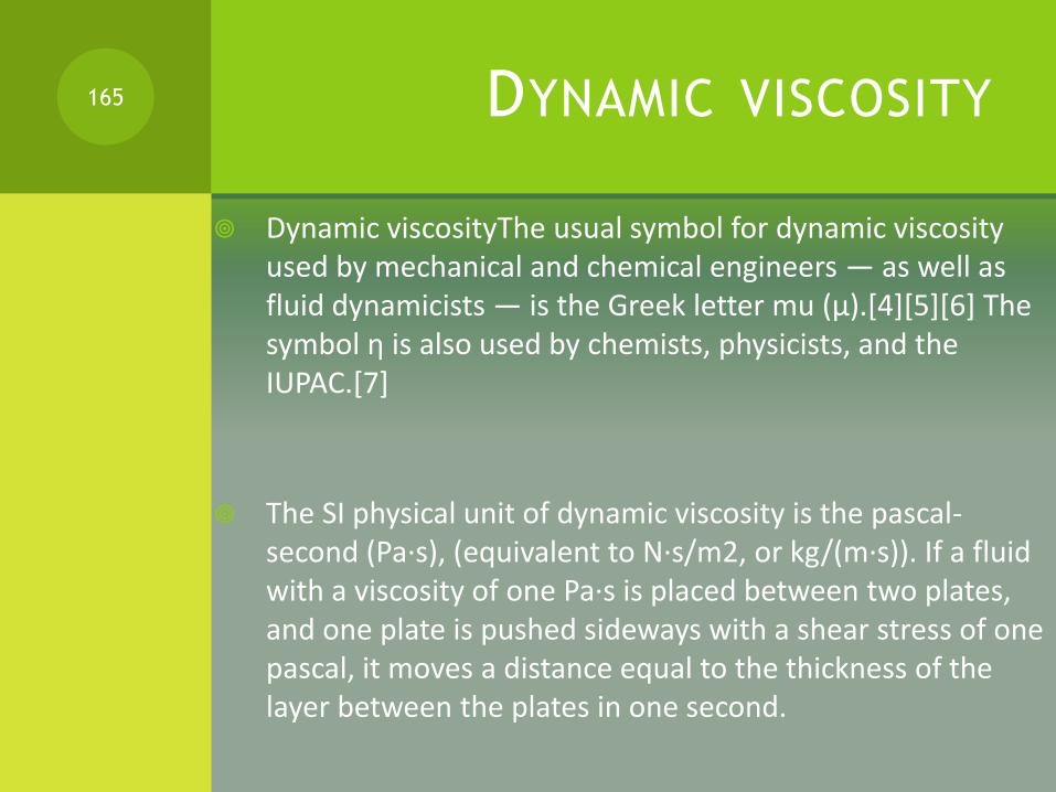
DYNAMIC VISCOSITY
Dynamic viscosityThe usual symbol for dynamic viscosity used by mechanical and chemical engineers — as well as fluid dynamicists — is the Greek letter mu (μ).[4][5][6] The symbol η is also used by chemists, physicists, and the IUPAC.[7]
The SI physical unit of dynamic viscosity is the pascal-second (Pa·s), (equivalent to N·s/m2, or kg/(m·s)). If a fluid with a viscosity of one Pa·s is placed between two plates, and one plate is pushed sideways with a shear stress of one pascal, it moves a distance equal to the thickness of the layer between the plates in one second.
165

The cgs physical unit for dynamic viscosity is the poise[8] (P), named after Jean Louis Marie Poiseuille.
It is more commonly expressed, particularly in ASTM standards, as centipoise (cP). Water at 20 °C has a viscosity of 1.0020 cP or 0.001002 kg/(m·s).
1 P = 1 g·cm−1·s−1.
1 Pa·s = 1 kg·m−1·s−1 = 10 P.
The relation to the SI unit is
1 P = 0.1 Pa·s,
1 cP = 1 mPa·s = 0.001 Pa·s.
166

KINEMATIC VISCOSITY
In many situations, we are concerned with the ratio of the inertial force to the viscous force (i.e. the Reynolds number, Re = VD / ν) , the former characterized by the fluid density ρ. This ratio is characterized by the kinematic viscosity (Greek letter nu, ν), defined as follows:
ν=μ/ρ The SI unit of ν is m2/s. The SI unit of ρ is kg/m3.
167

The cgs physical unit for kinematic viscosity is the stokes (St), named after George Gabriel Stokes. It is sometimes expressed in terms of centiStokes (cSt). In U.S. usage, stoke is sometimes used as the singular form.
1 St = 1 cm2·s−1 = 10−4 m2·s−1.
1 cSt = 1 mm2·s−1 = 10−6m2·s−1.
Water at 20 °C has a kinematic viscosity of about 1 cSt.
The kinematic viscosity is sometimes referred to as diffusivity of momentum, because it has the same unit as and is comparable to diffusivity of heat and diffusivity of mass. It is therefore used in dimensionless numbers which compare the ratio of the diffusivities.
168
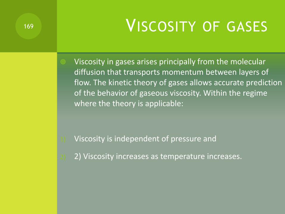
VISCOSITY OF GASES
Viscosity in gases arises principally from the molecular diffusion that transports momentum between layers of flow. The kinetic theory of gases allows accurate prediction of the behavior of gaseous viscosity. Within the regime where the theory is applicable:
1) Viscosity is independent of pressure and
2) 2) Viscosity increases as temperature increases.
169

JAMES CLERK MAXWELL
To understand why the viscosity is independent of pressure consider two adjacent boundary layers (A and B) moving with respect to each other. The internal friction (the viscosity) of the gas is determined by the probability a particle of layer A enters layer B with a corresponding transfer of momentum.
Maxwell's calculations showed him that the viscosity coefficient is proportional to both the density, the mean free path and the mean velocity of the atoms. On the other hand, the mean free path is inversely proportional to the density. So an increase of pressure doesn't result in any change of the viscosity.
170
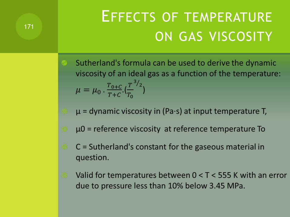
EFFECTS OF TEMPERATURE
ON GAS VISCOSITY
171

VISCOSITY FROM CORRELATIONS
172
GRAPHICAL APPROXIMATION
Fig 3.18 page 79 gives the viscosity of gases at atmospheric pressure and a different temperatures as a function of their density and molecular weight.
Fig 3.19 gives the effects of pressure and temperature on the viscosity calculated in fig 3.18.
173

CLASS WORK
Study of the paper “ Comparison of correlations for viscosity of sour natural gas “ by O. Jeje and L. Mattar in “Canadian International Petroleum Conference”.
174

VISCOSITY OF MIXTURES
175

FLASH SEPARATION OF GASES
176
INTRODUCTION
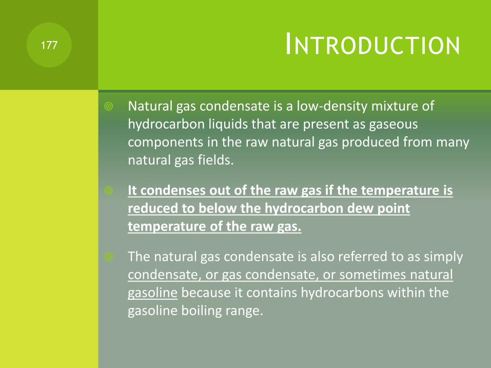
Natural gas condensate is a low-density mixture of hydrocarbon liquids that are present as gaseous components in the raw natural gas produced from many natural gas fields.
It condenses out of the raw gas if the temperature is reduced to below the hydrocarbon dew point temperature of the raw gas.
The natural gas condensate is also referred to as simply condensate, or gas condensate, or sometimes natural gasoline because it contains hydrocarbons within the gasoline boiling range.
177
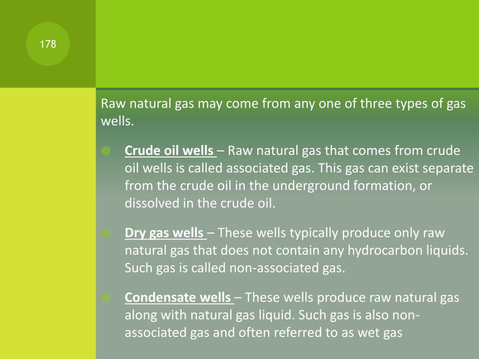
Raw natural gas may come from any one of three types of gas wells.
Crude oil wells – Raw natural gas that comes from crude oil wells is called associated gas. This gas can exist separate from the crude oil in the underground formation, or dissolved in the crude oil.
Dry gas wells – These wells typically produce only raw natural gas that does not contain any hydrocarbon liquids. Such gas is called non-associated gas.
Condensate wells – These wells produce raw natural gas along with natural gas liquid. Such gas is also non-associated gas and often referred to as wet gas
178
SEPARATION OF CONDENSATE179
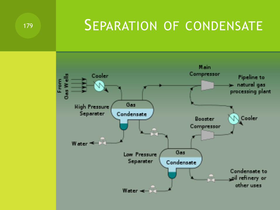
PROCESS DESCRIPTION
The raw natural gas feedstock from a gas well or a group of wells is cooled to lower the gas temperature to below its hydrocarbon dew point at the feedstock pressure and that condenses a good part of the gas condensate hydrocarbons.
The feedstock mixture of gas, liquid condensate and water is then routed to a high pressure separator vessel where the water and the raw natural gas are separated and removed.
The raw natural gas from the high pressure separator is sent to the main gas compressor.
180
The gas condensate from the high pressure separator flows through a throttling control valve to a low pressure separator.
The reduction in pressure across the control valve causes the condensate to undergo a partial vaporization referred to as a flash vaporization.
The raw natural gas from the low pressure separator is sent to a "booster" compressor which raises the gas pressure and sends it through a cooler and on to the main gas compressor.
181

At the raw natural gas processing plant, the gas will be dehydrated and acid gases and other impurities will be removed from the gas.
Then the ethane (C2), propane (C3), butanes (C4) and C5 plus higher molecular weight hydrocarbons (referred to as C5+) will also be removed and recovered as byproducts.
The water removed from both the high and low pressure separators will probably need to be processed to remove hydrogen sulfide before the water can be disposed of or reused in some fashion.
Some of the raw natural gas may be re-injected into the gas wells to help maintain the gas reservoir pressures.
182
LIQUID-VAPOR EQUILIBRIUM
It is convenient to represent a liquid-vapor equilibrium with the equilibrium constant K.
By definition: K= yi/xi
183

EQUILIBRIUM DATA184

185

FUGACITY OF GAS
In chemical thermodynamics, the fugacity (f) of a real gas is an effective pressure which replaces the true mechanical pressure in accurate chemical equilibrium calculations.
It is equal to the pressure of an ideal gas which has the same chemical potential as the real gas.
For example, nitrogen gas (N2) at 0°C and a pressure of 100 atm has a fugacity of 97.03 atm. This means that the chemical potential of real nitrogen at a pressure of 100 atm has the value which ideal nitrogen would have at a pressure of 97.03 atm.
186
Fugacities are determined experimentally or estimated for various models such as a Van der Waals gas that are closer to reality than an ideal gas.
The ideal gas pressure and fugacity are related through the dimensionless fugacity coefficient φ:
Φ = f/P
For nitrogen at 100 atm, the fugacity coefficient is 97.03 atm / 100 atm = 0.9703. For an ideal gas, fugacity and pressure are equal so is 1.
187
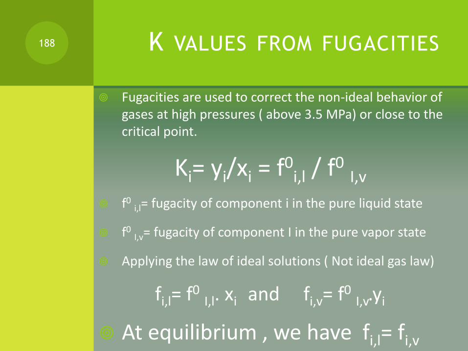
K VALUES FROM FUGACITIES
Fugacities are used to correct the non-ideal behavior of gases at high pressures ( above 3.5 MPa) or close to the critical point.
Ki= yi/xi = f0i,l / f0
I,v
f0i,l= fugacity of component i in the pure liquid state
f0I,v= fugacity of component I in the pure vapor state
Applying the law of ideal solutions ( Not ideal gas law)
fi,l= f0I,l. xi and fi,v= f0
I,v.yi
At equilibrium , we have fi,l= fi,v
188

Fugacity coefficient for gas φi = fi/ P.yi
For liquids : φi,l = fi/ P.xi ?
At equilibrium : Ki= φi,l / φi,v
K values pages 140-154
189

RELATIVE VOLATILITY
The relative volatility αi for component (i) is the ratio of its distribution coefficient and the distribution coefficient of a reference component (r):
αi = ( Ki/Kr)
190
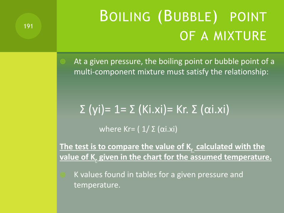
BOILING (BUBBLE) POINT
OF A MIXTURE
At a given pressure, the boiling point or bubble point of a multi-component mixture must satisfy the relationship:
Σ (yi)= 1= Σ (Ki.xi)= Kr. Σ (αi.xi)
where Kr= ( 1/ Σ (αi.xi)
The test is to compare the value of Kr calculated with the value of Kr given in the chart for the assumed temperature.
K values found in tables for a given pressure and temperature.
191
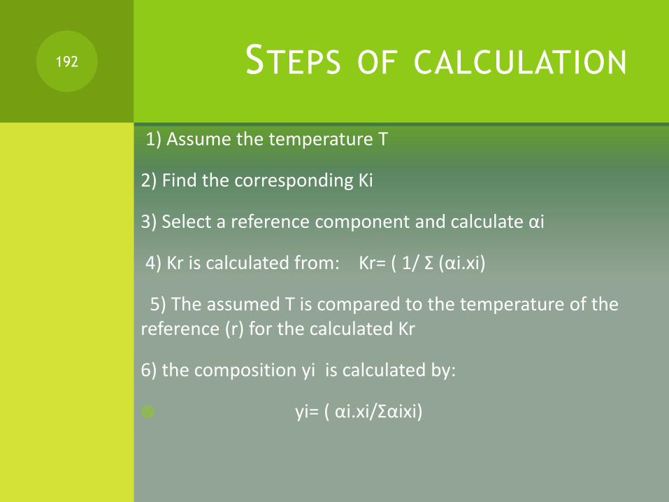
STEPS OF CALCULATION
1) Assume the temperature T
2) Find the corresponding Ki
3) Select a reference component and calculate αi
4) Kr is calculated from: Kr= ( 1/ Σ (αi.xi)
5) The assumed T is compared to the temperature of the reference (r) for the calculated Kr
6) the composition yi is calculated by:
yi= ( αi.xi/Σαixi)
192

DEW POINT OF A MIXTURE
Σxi = Σ (yi/Ki)=(1/Kr).Σ (yi/αi)
193

CLASS WORK
Do example 5.1 page 117 and 5.2 page 118
194

FLASH CALCULATION
195
NGL STABILIZATION:
DEW POINT CONTROL
Once the NGL has been extracted from the gas, it must be stabilized to meet sales specifications.
In some cases, the NGL product is a stabilized condensate consisting only of C5+ having a vapor pressure less than 14.4 psia.
In other cases , the NGL product is a C4+ mixture which can be added to crude oil stream for sale.
In NGL recovery, the NGL product is a C2+ or C3+ which can be fractionated to produce C1, C2, C3, C4 and C5+
196
STABILIZATION BY DISTILLATION
Stabilization of natural gas liquids (NGLs) or field condensate is a process utilizing controlled flashing and in some cases, a distillation of the liquid to allow it to be stored in atmospheric vessels.
The distillation of the liquid can also used to remove objectionable non-hydrocarbon components, most notably CO2, from the sales liquid.
197

MEMBRANE TECHNOLOGY
An improved, membrane-based method of treating gas evolved during natural gas liquids (NGL) stabilization, to separate the very light hydrocarbon gases, methane in particular, from the heavier hydrocarbons.
The membrane acts as a demethanizer and establishes a vapor/liquid equilibrium during phase separation that is different than would otherwise obtain.
This can increase NGL production and reduce the weight of C3+ hydrocarbons in the off-gas from the stabilizing phase separators.
198
FLASH CALCULATION
Flash (or partial) evaporation is the partial vapor that occurs when a saturated liquid stream undergoes a reduction in pressure by passing through a throttling valve or other throttling device.
This process is one of the simplest unit operations. If the throttling valve or device is located at the entry into a pressure vessel so that the flash evaporation occurs within the vessel, then the vessel is often referred to as a flash drum.
If the saturated liquid is a multi-component liquid (for example, a mixture of propane, isobutane and normal butane), the flashed vapor is richer in the more volatile components than is the remaining liquid.
199
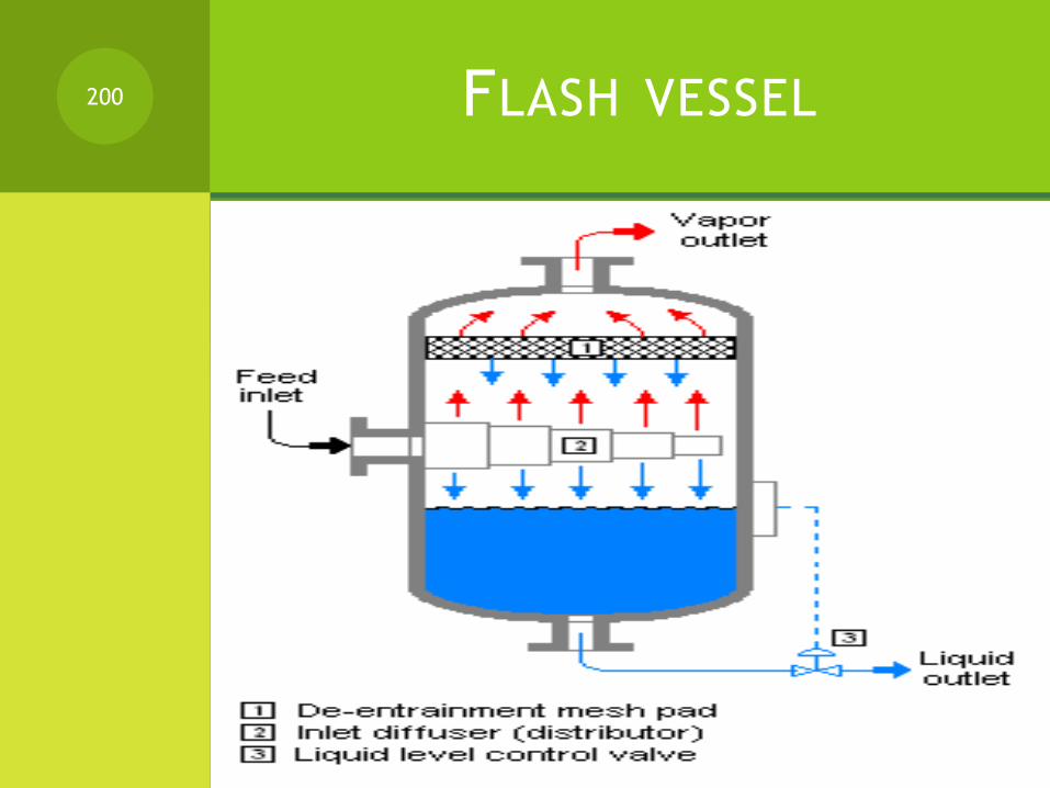
FLASH VESSEL200
MATERIAL BALANCE
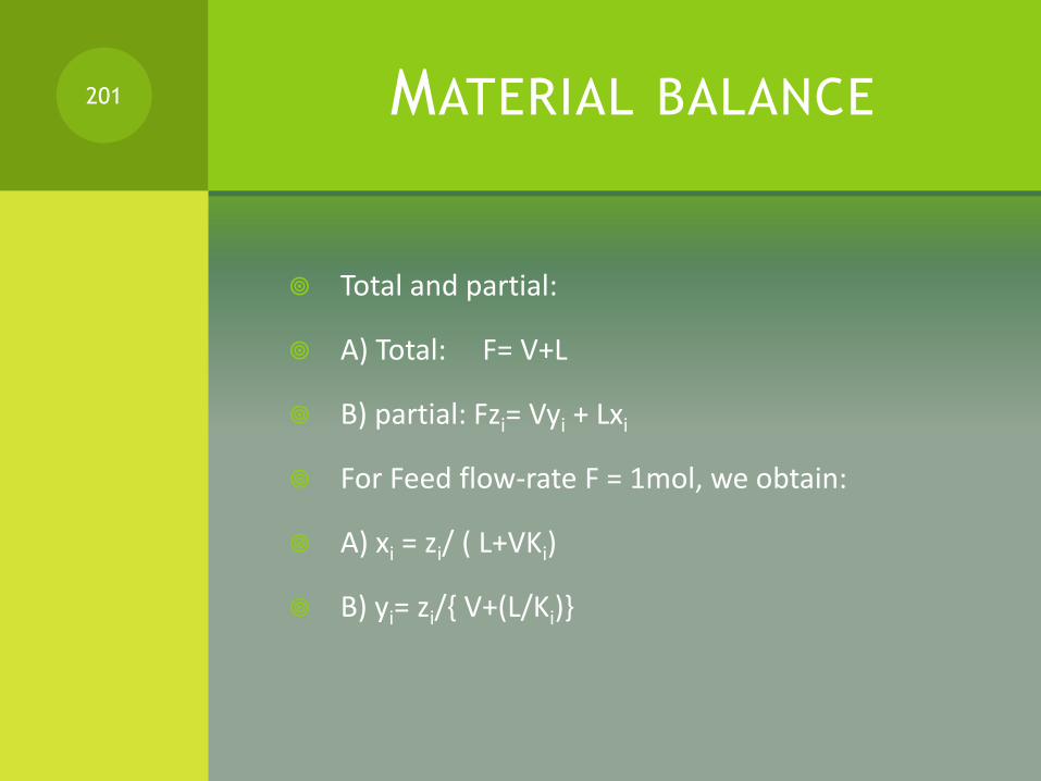
Total and partial:
A) Total: F= V+L
B) partial: Fzi= Vyi + Lxi
For Feed flow-rate F = 1mol, we obtain:
A) xi = zi/ ( L+VKi)
B) yi= zi/{ V+(L/Ki)}
201

Knowing that Σxi= 1 and Σyi=1 , we will obtain:
Σxi = Σ{zi/ ( L+VKi)} =1
Σyi= Σ [zi/{ V+(L/Ki)}] =1
At equilibrium: Σyi – Σxi =0, we obtain the flash equation:
Σ{zi ( Ki-1)} / {V( Ki-1) +1} =0
202

STEPS FOR SOLVING FLASH
CALCULATION
1) find K from P and T
2) assume V and L ( L=F-V)
3) solve the flash equation
4) if not equal to zero, assume new V and L
Solve example 5.3 page 119.
203

NGL FRACTIONATION BY
DISTILLATION
204

SELECTION OF KEY
COMPONENTS
Selecting Key components: If we have a mixture ( A,B,C,D), the separation should be only between two of the four components:
Ex:
A and B are light and heavy keys
B and C are light and heavy keys
C and D are light and heavy keys.
205

LIGHT AND HEAVY
COMPONENTS
If we want to separate B and C
B is called the Light (L) key
C is called the Heavy (H) key
A is called light component
D is called heavy component
It is assumed that the light components are all at the top and the heavy components all in the bottom.
206

MINIMUM OF STAGES BY FENSKE
EQUATION
The Fenske equation used for a binary distillation is also used for multicomponent distillation to estimate the minimum number of stages at total reflux:
Nm=(log {xLD. D/xHD. D} .{xHW. W/xLW. W})/ log ( αLAV )
With αLAV = √ (αLD. αLW )
207

DISTRIBUTION OF THE OTHER
COMPONENTS
(xi,D. D/xiw. W)= (αi,AV)Nm.(xHD.D/xHW.W)
208

RMINIMUM
Underwood shortcut method is used for the Minimum Reflux ratio.
Solving the two following equations:
1-q= Σ {αi,av.xiF/(αi,av-θ)}
Rm+1= Σ {αi,av.xiD/(αi,av-θ)}
1) As an approximation, the values of xiD in the second equation can be taken from the Fenske equation.
209

NUMBER OF PLATES
2) The value of θ of the first equation is found by trial and error. It is located between the α value of the light and heavy keys.
3) Having the value of θ , we find Rm from the second equation.
4) R= 1.5 Rm
4) Using Figure 11.7.3, we can estimate the number of stages N
210

LOCATION OF THE FEED
Log ( Ne/Ns)= 0.206. log [(xhf/xlf).(W/D).( xlw/xld)2 ]
Ne is the number of theoretical stages above the feed plate.
Ns is the number of theoretical stages below the feed plate.
211

EXAMPLE OF NGL FRACTIONATION
UNIT
212
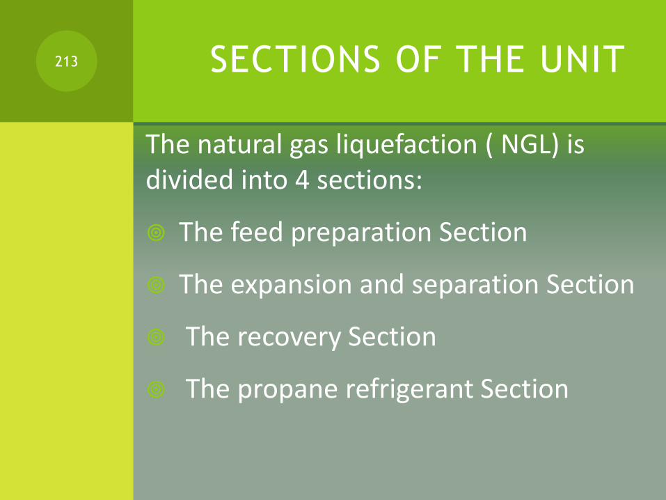
SECTIONS OF THE UNIT
The natural gas liquefaction ( NGL) is divided into 4 sections:
The feed preparation Section
The expansion and separation Section
The recovery Section
The propane refrigerant Section
213
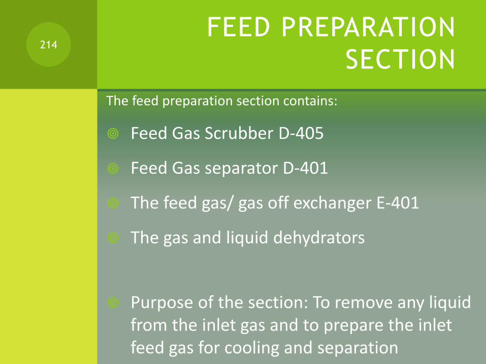
FEED PREPARATION
SECTION
The feed preparation section contains:
Feed Gas Scrubber D-405
Feed Gas separator D-401
The feed gas/ gas off exchanger E-401
The gas and liquid dehydrators
Purpose of the section: To remove any liquid from the inlet gas and to prepare the inlet feed gas for cooling and separation
214
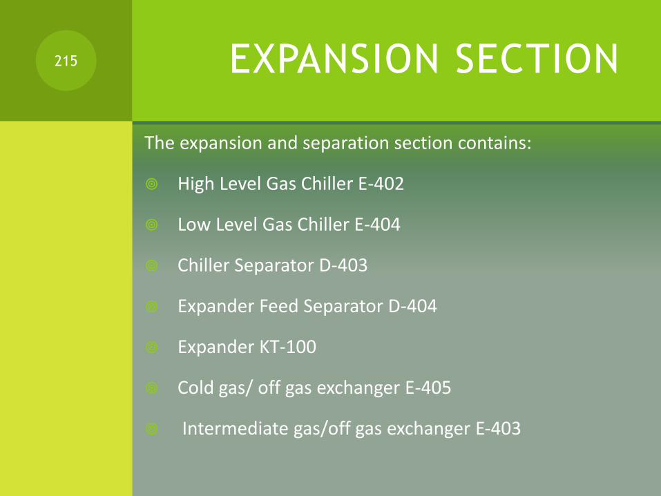
EXPANSION SECTION
The expansion and separation section contains:
High Level Gas Chiller E-402
Low Level Gas Chiller E-404
Chiller Separator D-403
Expander Feed Separator D-404
Expander KT-100
Cold gas/ off gas exchanger E-405
Intermediate gas/off gas exchanger E-403
215
OBJECTIVE OF
EXPANSION SECTION
Purpose of the section:
Cool the inlet feed gas in a series of heat exchangers and to provide several feeds at various temperatures to the demethanizer D-402
216

SEPARATION SECTION
The separation section contains:
Demethanizer Column D-402
Demethanizer Reboiler E-406
Compression Section K-100 and KT-100
Two product booster pumps P-401A/B
217

REFRIGERATION
SECTION
Propane refrigerant is used
Cooling takes place in the high Level Chiller E-402 and Low Level Chiller E-404
218

PROCESS DESCRIPTION
219

Pressurized inlet gas enters NGL recovery Unit
Entrained liquid is removed by scrubber
The liquid from the scrubber is dried and then feed the demethaniser
The gas from the scrubber is dried and then cooled by the overhead gas from the demethanizer
220
The gas then enters the feed gas separator D-401
The liquid from the separator combines with the liquid from the bottom of the scrubber to go to the demethanizer
- The gas leaving the separator is chilled by passing through three heat exchangers
- high level gas chiller E-402
- Intermediate gas-gas heat exchanger E-403
- Low level Chiller E-404
221

From the low level chiller, gas enters the chiller separator D-403 which remove any additional liquid
- The remaining gas is cooled in a cold gas exchanger E-405
- Then enters the expander feed separator KT 100
- The liquid from the expander separator enters the demethanizer
222
The gas from the expander separator E-404 enters the expander
- The expander reduces the temperature and pressure of the gas and condenses as much C2+ as possible
- The gas stream from the expander D-404 feeds the demethanizer
- the expander is also used to provide power to the residue gas compressor
223

PROCESS CONTROL SYSTEM
224
FEED PREPARATION SECTION
TI-350: indicates inlet feed gas to gas Scrubber D-405 ( 0-650C)
HC-350: This is a manual valve to control the flow of inlet gas to the feed gas scrubber D-405
HS-400: This hand switch initiates the plant emergency shut down by closing the inlet feed valve HC-350
225

FI-405: Indicates the inlet feed gas vapor from the top of the scrubber D-405 ( 0 -1600 kNm3/d
FI-406: Indicates the liquid flow from the bottom of D-405 ( 0-50 m3/h)
LC-350: this controls the level of liquid in the scrubber D-405 by regulating the flow of methane to the D-402. Flow shown by FI-406
226

FEED GAS SEPARATOR D-401
LC-411: controls the liquid level in the feed gas separator D-401 by regulating the flow of liquid from the bottom of D-401 to tray 20 of D-402
TI-400: Indicates the vapor temperature exiting the top of D-401
227
TYPE OF GASSES.
Exercise B): Use the internet or any other sources to answer the following questions:
1. What is an associated gas?
2. Search (internet or any other source) for a typical associated gas composition of an oil field, preferably in the UAE, and attached/copy the table.
3. What is a non-associated gas.
4. What is the difference between a wet gas and a dry gas.
(include a table showing an example of a mol% of a dry gas components compared to a wet gas)
(Will discuss and will review the answers after you are done… next slide)
228
HIGH LEVEL GAS CHILLER
LC-401:This controls the propane refrigerant level in the shell side of the High level gas chiller E-402
LAH-401: this alarm will start when the level of the liquid in the shell side of E-402 rises above 80% as read in LC-401
229

PC-405: from 0 to 7 Barg , this controls the pressure in E-402 by regulating the flow of propane vapor from the chiller to the inlet of second stage of compressor ( not simulated)
PAH-405: This alarm when the pressure in the gas chiller E-402 rises above 2.94 as read in PC-405
230

LOW LEVEL GAS CHILLER
LC-402:This controls the liquid propane in the shell side of E-404 by regulating the flow of propane from the propane tube side of E-409
LAHL-402: Alarm when the propane refrigerant level in shell side of E-404 rises above 80% or falls below 20%
PC-406 : from 0 to 3.5 barg, this controls the pressure in E-404 by regulating the flow of propane vapor from the chiller to first stage of the compressor ( not simulated)
231
PAH-406: Alarm when the pressure in E-404 rises above 0.62 Barg as read in PC-406
Ti-404: indicates the temperature of the effluent from the tube shell of E-404. Indicates also the temperature of the feed entering D-403
LC -403: Controls the level of D-403 by regulating the flow from the bottom of the separator to tray 14 of D-402
232
EXPANSION SECTION
PC-401:from 0 to 50 Barg, this controls the pressure of the expander feed separator through a split-range control. This is also the pressure at the inlet to the expander section.
PAHL- 401: alarm when the pressure in D-404 rises above 48.0 Barg or falls below 44.13 Barg as read at PC-401
TI-405: Indicates the temperature of the feed gas as it enters D-404. this is also the temperature of the feed gas from the tube side of E-405
233
LC-404:this controls the liquid level in the chiller separator D-404 by regulating the flow of liquid from the bottom of separator to tray 8 of D-402
LAH-404: Alarm when the liquid level in D-404 rises above 80% as read at LC-404
HC-401: Manual control adjusts the position of the inlet louver vanes in expander4 section
HS-401:switch that determines witch controller HC-401 or PC-401 will regulate the position of the expander inlet vanes
234

FC-403: from 0 to 1600 kNm3/d, this regulates the inlet flow to the compressor section
FAL-403: Alarm when compressor recycle ( anti-surge) flow falls below 750.KNm3/d as read in FC-403
HS 100: this switch operates the expander section KT-100. When the switch in ON , the expander is in operation
235
DE-METHANIZER
AAH-401 : Alarm when the concentration of methane in the bottom of the demethanizer D-402, rises above 2% as read in AC-401
AC-401: Controls the methane composition in the bottom of the demethanizer D-402 from 0 to 10% by sending a remote set-point signal to the demethanizer reboiler effluent temperature controller TC-403
236
FI-408: this instrument indicates the flow of the methane product from the bottom of the demethanizer D-402 to the product pipeline . This flow is regulated by the Demethanizer level controller LC-400.
HS-401A-B : this are the product booster pumps. These pumps draw methane product from the bottom of the demethanizer D-402 and send it to the product line
237
LAHL-400: This alarm fires when the level in the bottom of the demethanizer D-402 rises above 80% or below 20% as read at LC-400
LC-400 : this controls the level in the bottom of the demethanizer by regulating the flow of methane product from the bottom of D-402 as read in FI-408
238

PAHL-402 : Alarm when the pressure in the top of D-402 rises above 13.48 Barg or below 10.69 Barg as read in PC-402
PC-402: Controls the pressure in the top of D-402 by regulating the flow of vapor from the discharge of the compression section K-100
239

TAH-401 D-402 TRAY-1 Temperature:
This alarm is on when the temperature of TRAY-1 of D-402, rises above -95C as read in TC-401
TC-401( -125C to -200C):
This controls the temperature of the feed of tray-1 of D-402 by regulating the amount of gas bypassing KT-100 and flows directly from the top of D-403
240

TC-403: ( from -20C to 100C):
This controls the effluent temperature from the D-402 re-boiler E-406 by regulating the flow of heating medium to the re-boiler. This controller can receive a signal control from the D-402 methane composition controller AC-401
241

TI-410: Indicator top of D-402
-1250C to -500C
TI-411: Indicator tray 24 of D-402
-1000C to 100C
TI-412 : Indicator of bottom D-402
-500C to 100C
242
CLASS WORK
Work the NGL fractionation plant using hysys.
243

ACID GAS REMOVAL
244

ACID & SOUR GAS
Acid gas is natural gas or any other gas mixture which contains significant amounts of hydrogen sulfide (H2S), carbon dioxide (CO2), or similar contaminants.
The terms acid gas and sour gas are often incorrectly treated as synonyms.
Strictly speaking, a sour gas is any gas that contains hydrogen sulfide in significant amounts;
Hydrogen sulfide is a toxic gas. It also restricts the materials that can be used for piping and other equipment for handling sour gas, as many metals are sensitive to sulfide stress cracking.
245
GLOBAL WARMING
an acid gas is any gas that contains significant amounts of acidic gases such as carbon dioxide (CO2) or hydrogen sulfide.
Thus, carbon dioxide by itself is an acid gas but not a sour gas.
Carbon dioxide is the main gas responsible for global warming.
246

CONVERTING H2S
Before a raw natural gas containing hydrogen sulfide and/or carbon dioxide can be used, the raw gas must be treated to reduce impurities to acceptable levels and this is commonly done with an amine gas treating process.
The removed H2S is most often subsequently converted to by-product elemental sulfur in a Claus process
or alternatively converted to valuable sulfuric acid in a WSA Process unit.
247
REASONS FOR REMOVING
CO2 AND H2S
Carbon dioxide, hydrogen sulfide, and other contaminants are often found in natural gas streams.
CO2 when combined with water creates carbonic acid which is corrosive. CO2 also reduces the BTU value of gas and
in concentrations of more that 2% or 3 % the gas is unmarketable.
H2S is an extremely toxic gas that is also tremendously corrosive to equipment.
Amine sweetening processes remove these contaminants so that the gas is marketable and suitable for transportation.
248

DIFFERENT PROCESSES
Chemical solvent processes
Physical solvent processes
Dry adsorbents processes
249

CHEMICAL SOLVENTS
Monoethanolamine (MEA)
* Diethanolamine (DEA)
* Methyl- Diethanolamine (MDEA)
* Diglycolamine (DGA)
* Hot Potassium Carbonate
250
PHYSICAL SOLVENTS
Physical solvent processes:
* Selexol
* Propylene Carbonate
* Sulfinol
* Rectisol
251
DRY ADSORBENTS
* Molecular sieve
* Activated charcoal
* Iron sponge
* Zinc oxide
252
AMINE GAS SWEETENING
SOLUTIONS
Amine gas sweetening is a proven technology that removes H2S and CO2 from natural gas and liquid hydrocarbon streams through absorption and chemical reaction.
Each of the amines offers distinct advantages to specific treating problems.
253
MEA
Used in low pressure natural gas treatment applications requiring stringent outlet gas specifications
254
MDEA
MDEA (Methyldiethanolamine)
Has a higher affinity for H2S than CO2 which allows some CO2 "slip" while retaining H2S removal capabilities.
255
DEA
DEA (Diethanolamine)
Used in medium to high pressure treating
256
PIPERAZINE
Nowadays, Piperazine mixed with MDEA or the hindered amine AMP are the most effective amine mixtures because :
1) Piperazine has fast kinetics with CO2 and H2S
2) MDEA and AMP require less energy for the regeneration of the amine.
257
IONIC LIQUIDS
Some Ionic liquids are now under investigation in many laboratories around the world as the new solvent to be used for acid gas removal:
They have the advantage to use less energy than amines for their regeneration
BUT they have slow kinetics with the acid gases, they are very viscous and still expensive in the market.
258
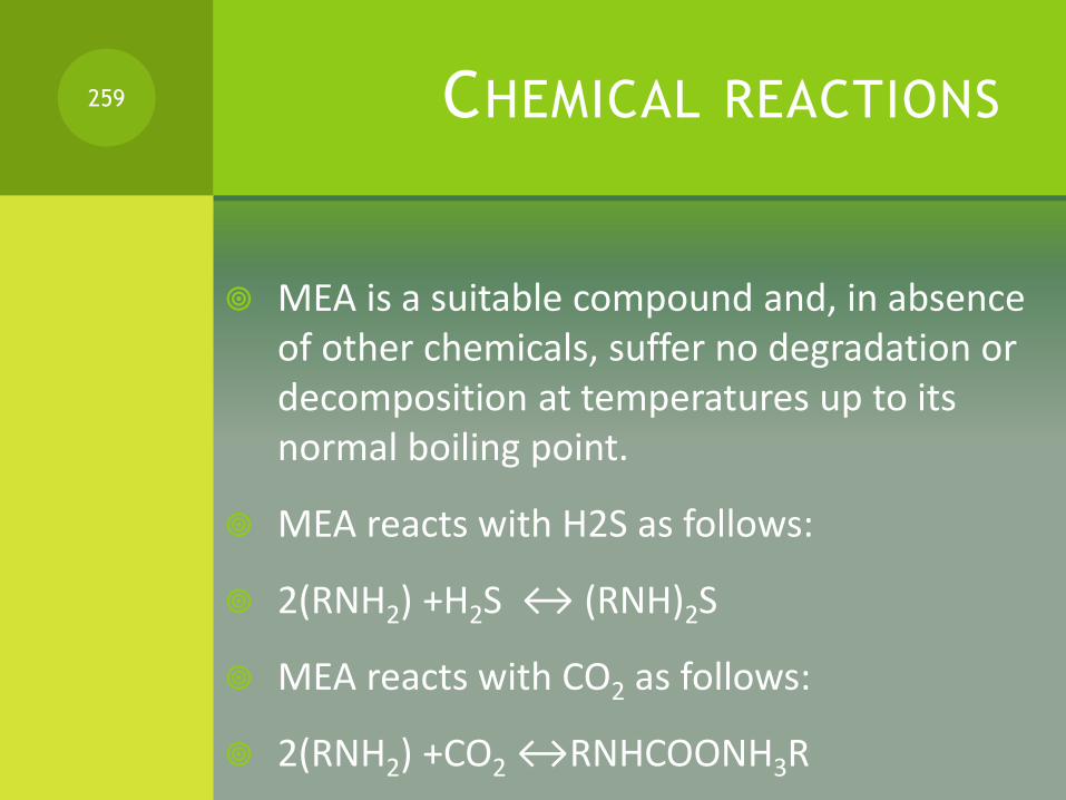
CHEMICAL REACTIONS
MEA is a suitable compound and, in absence of other chemicals, suffer no degradation or decomposition at temperatures up to its normal boiling point.
MEA reacts with H2S as follows:
2(RNH2) +H2S ↔ (RNH)2S
MEA reacts with CO2 as follows:
2(RNH2) +CO2 ↔RNHCOONH3R
259

PROCESS FOR ACID REMOVAL
BY AMINE SOLUTIONS260
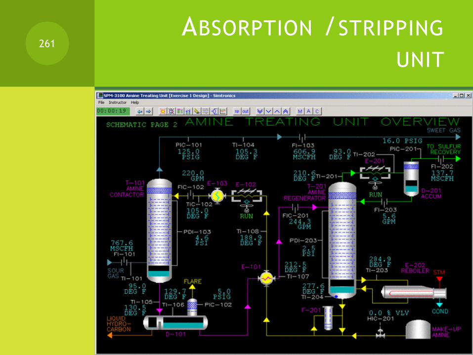
ABSORPTION /STRIPPING
UNIT261

ABSORPTION UNIT262

STRIPPING UNIT263

PROCESS DESCRIPTION
The Amine Treating Unit removes CO2 and H2S from sour gas and hydrocarbon streams in the Amine Contactor. The Amine (MDEA) is regenerated in the Amine Regenerator, and recycled to the Amine Contactor.
The sour gas streams enter the bottom of the Amine Contactor. The cooled lean amine is trim cooled and enters the top of the contactor column.
The sour gas flows upward counter-current to the lean amine solution. An acid-gas-rich-amine solution leaves the bottom of the column at an elevated temperature, due to the exothermic absorption reaction.
The sweet gas, after absorption of H2S by the amine solution, flows overhead from the Amine Contactor.
264
The Rich Amine Surge Drum allows separation of hydrocarbon from the amine solution.
Condensed hydrocarbons flow over a weir and are pumped to the drain.
The rich amine from the surge drum is pumped to the Lean/Rich Amine Exchanger.
The stripping of H2S and CO2 in the Amine Regenerator regenerates the rich amine solution.
The Amine Regenerator Reboiler supplies the necessary heat to strip H2S and CO2 from the rich amine, using steam as the heating medium.
265
Acid gas, primarily H2S and water vapor from the regenerator is cooled in the Amine Regenerator Overhead Condenser.
The mixture of gas and condensed liquid is collected in the Amine Regenerator Overhead Accumulator. The uncondensed gas is sent to Sulfur Recovery.
The Amine Regenerator Reflux Pump, pumps the condensate in the Regenerator Accumulator, mainly water, to the top tray of the Amine Regenerator A portion of the pump discharge is sent to the sour water tank.
266
Lean amine solution from the Amine Regenerator is cooled in the Lean/Rich Exchanger.
A slipstream of rich amine solution passes through a filter to remove particulates and hydrocarbons, and is returned to the suction of the pump.
The lean amine is further cooled in the Lean Amine Air Cooler, before entering the Amine Contactor.
267
PRODUCT SPECIFICATIONS
The Amine Treating Unit removes CO2 and H2S from sour gas and hydrocarbon streams totaling 14.5 MMSCFD.
The acid contaminants are absorbed by counter flowing amine solution (MDEA).
The stripped gas is removed overhead, and the amine is sent to the regenerator.
In the regenerator, the acidic components are stripped by heat and reboiling action and disposed of, and the amine is recycled.
268

EQUIPMENT'S SPECIFICATIONS
The amine contactor is 5 feet in diameter by 65 feet tangent to tangent with 22 trays.
The Rich Amine Surge drum, D-101, provides approximately 30 minutes of residence time which allow separation of the hydrocarbon from the amine solution.
The Amine Regenerator is 8 feet in diameter by 70 feet tangent to tangent with 22 trays.
The Regenerator Reboiler, E-202, uses 60 psig steam as heating medium which provides the heat for regeneration of the amine solution.
269

PROCESS CONTROL OF THE UNIT
270
PROCESS CONTROL OF THE
UNIT
The sour gas stream, 14.5 MMSCFD, enters the bottom of the Amine Contactor at 95 0F and 140 psig.
The cooled lean amine is trim cooled in exchanger E-103 and enters the top of the absorber column at 105 0F.
The lean amine solution temperature is 100 higher than the feed gas to prevent any hydrocarbon condensation and foaming problems.
This temperature differential is maintained by TDIC-103, which allows bypassing of lean amine around the Lean Amine Trim Cooler E-103.
271

The sour gas flows upward counter-current to the lean amine solution in T-101.
An acid-gas-rich-amine solution leaves the bottom of the column at an elevated temperature, 1350 F, due to the exothermic absorption reaction.
The rich MDEA solution temperature is monitored by TI-105.
Rich amine leaves the bottom of the column on level control LIC-101 to the Rich Amine Surge Drum D-101.
272
The sweet gas, after absorption of H2S by the MDEA solution, flows overhead from T-101 under pressure control PIC-101, monitored by the H2S and CO2 analyzers, AI-102 and AI-103.
The temperature and flow rate of the gas are monitored with TI-104 and FI-101.
The Rich Amine Surge Drum D-101 allows the amine solution 30 minutes of residence time, which allows separation of hydrocarbon from the amine solution.
The drum pressure is maintained by a backpressure controller, PIC-102, at 5 psig.
Condensed hydrocarbons flow over a weir and are pumped to the drain system using P-102.
273
The rich amine from the surge drum is pumped by P-101 to the Lean/Rich Amine Exchanger E-101.
The rich amine enters the tube side at 1350 F, where it is heated to 2260 F by the hot lean amine solution from the regenerator bottoms.
The hot lean amine solution enters the Lean/Rich Exchanger on the shell side at 265 0 F.
The stripping of H2S and CO2 in the Amine Regenerator, T-201, regenerates the rich amine solution.
The Amine Regenerator Reboiler supplies the necessary heat to strip H2S from the rich amine, using 60-psig steam as the heating medium.
274
Acid gas, primarily H2S and water vapor from the regenerator is cooled to 120 0F in the Amine Regenerator Overhead Condenser.
The temperature of the overhead gas is monitored by TI-202 The mixture of gas and condensed liquid is collected in the Amine Regenerator Overhead Accumulator.
The pressure is maintained at 16 psig with PIC-201 controlling the acid gas from the Regenerator Accumulator, D-20, to Sulfur Recovery.
275
The condensate in the Regenerator Accumulator D-201, mainly water, is pumped by the Amine Regenerator Reflux Pump, P-202, to the top tray of the Amine Regenerator.
The reflux flow is regulated by level controller LIC-201 and is monitored by FI-203. A part of the pump discharge is sent to the sour water tank.
Lean amine solution from the Amine Regenerator is cooled from 265 degrees F to 189 degrees F in the Lean/Rich Exchanger.
A slipstream of rich amine solution is controlled by PDIC-202 through a filter F-201 to remove particulates and hydrocarbons, and returned to the suction of P-201.
The lean amine is further cooled in the Lean Amine Air Cooler, E-102, to 130 0 F.
276

ADVANCED CONTROL
The cooler the lean amine temperature, the better the H2S absorption. However, lowering the MDEA solution temperature below the gas inlet temperature can cause hydrocarbons to condense with resulting foaming.
The lean amine solution temperature is maintained 100
higher than the feed gas to the Amine Contactor. TDIC-103 allows bypassing of lean amine around the Lean Amine Trim Cooler, E-103, to maintain this 100 difference.
277

SULFUR RECOVERY UNIT:
CLAUS PROCESS
278

SULFUR RECOVERY PROCESS
The most practical method for converting hydrogen sulfide to elementary sulfur
Best suited for gases containing more than 50% hydrogen sulfide is the
PARTIAL COMBUSTION PROCESS.
279
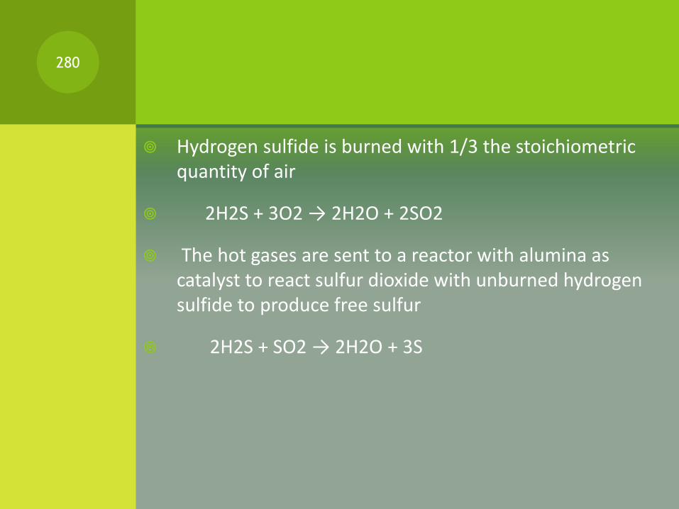
Hydrogen sulfide is burned with 1/3 the stoichiometric quantity of air
2H2S + 3O2 → 2H2O + 2SO2
The hot gases are sent to a reactor with alumina as catalyst to react sulfur dioxide with unburned hydrogen sulfide to produce free sulfur
2H2S + SO2 → 2H2O + 3S
280
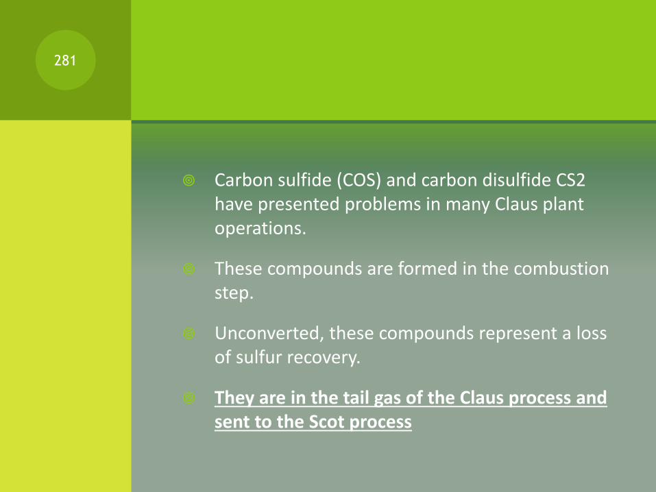
Carbon sulfide (COS) and carbon disulfide CS2 have presented problems in many Claus plant operations.
These compounds are formed in the combustion step.
Unconverted, these compounds represent a loss of sulfur recovery.
They are in the tail gas of the Claus process and sent to the Scot process
281

CLAUS PROCESS282
GAS DEHYDRATION PROCESS
283

Natural Gas usually contains significant quantities of water vapor.
Changes in temperature and pressure condense this vapor altering the physical state from gas to liquid to solid.
This water must be removed in order to protect the system from corrosion and hydrate formation.
284

DALTON’S LAW
In 1810, an English scientist by the name of John Dalton stated that the total pressure of a gaseous mixture is equal to the sum of the partial pressures of the components.
This statement, now known as Dalton's Law of Partial Pressures, allows us to compute the maximum volume of water vapor that natural gas can hold for a given temperature and pressure.
The wet inlet gas temperature and supply pressures are the most important factors in the accurate design of a gas dehydration system.
Without this basic information the sizing of an adequate dehydrator is impossible
285

EXAMPLE
As an example, one MMSCF (million standard cubic feet) of natural gas saturated @ 80 0F and 600 PSIG (pound per square inch gauge) will hold 49 pounds of water.
At the same pressure (600 PSIG) one MMSCF @ 120 0 F will hold 155 pounds of water.
Common allowable water content of transmission gas ranges from 4 to 7 pounds per MMSCF.
Based upon the above examples, we would have two very different dehydration problems as a result of temperature alone.
There are many other important pieces of design information required to accurately size a dehydration system. These include pressures, flow rates and volumes.
286

HYDRATES IN NATURAL GAS
All gasses have the capacity to hold water in a vapor state. This water vapor must be removed from the gas stream in order to prevent the formation of solid ice-like crystals called hydrates.
Hydrates can block pipelines, valves and other process equipment.
The dehydration of natural gas must begin at the source of the gas in order to protect the transmission system.
287
ELIMINATION OF WATER
The source of the gas moved through the transmission lines may be producing wells or developed storage pools.
Pipeline drips installed near well heads and at strategic locations along gathering and trunk lines will eliminate most of the free water lifted from the wells in the gas stream.
Multi stage separators can also be deployed to insure the reduction of free water that may be present.
288
PIPELINE DRIPS
Natural gas transmission pipelines often contain liquids that can interfere with the proper operation of the pipeline and related equipment such as compressors, regulators, filters, meters and valves.
The liquid contaminants normally include hydrocarbon condensations, lubrication oils, produced water, and chemicals used in production, treatment, compression or dehydration of the gas.
Gas transmission pipelines have typically used below grade liquid separators known as “drips” that are installed in the pipeline at regular intervals to collect the liquids carried in a gas stream.
289

PIPELINE DRIPS290

MULTISTAGE SEPARATOR291
INDUSTRIAL PROCESSES TO
REMOVE WATER
Water vapor moved through the system must be reduced to acceptable industry levels.
Typically, the allowable water content in gas transmission lines ranges from 4 lb. to 7 lb. per MMSCF.
There are basically three methods employed to reduce this water content. These are:
1. Joule-Thomson Expansion
2. Solid Desiccant Dehydration
3. Liquid Desiccant Dehydration
292
JOULE THOMSON VALVE
Joule-Thomson Expansion utilizes temperature drop to remove condensed water to yield dehydrated natural gas.
The principal is the same as the removal of humidity from outside air as a result of air conditioning in your house.
In some cases glycol may be injected into the gas stream ahead of the heat exchanger to achieve lower temperatures before expansion into a low temperature separator.
293
SOLID DESICCANT
DEHYDRATION
Solid desiccant dehydration, also known as solid bed, employs the principal of adsorption to remove water vapor.
Adsorbents used include:
silica gel (most commonly used),
molecular sieve (common in NGV dryers),
activated alumina and
activated carbon.
294
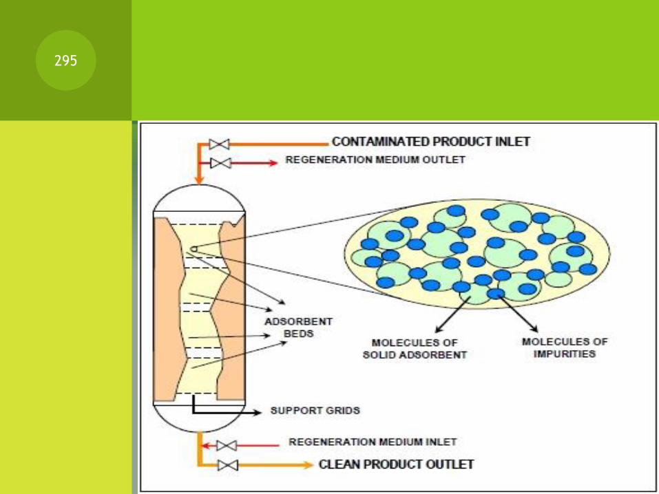
295
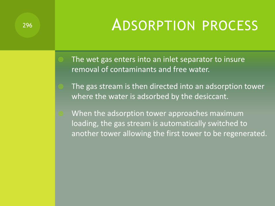
ADSORPTION PROCESS
The wet gas enters into an inlet separator to insure removal of contaminants and free water.
The gas stream is then directed into an adsorption tower where the water is adsorbed by the desiccant.
When the adsorption tower approaches maximum loading, the gas stream is automatically switched to another tower allowing the first tower to be regenerated.
296

REGENERATION
Heating a portion of the mainstream gas flow and passing it through the desiccant bed regenerates the loaded adsorbent bed.
The regeneration gas is typically heated in an indirect heater. This unsaturated regeneration gas is passed through the bed removing water and liquid hydrocarbons.
The regeneration gas exits the top of the tower and is cooled most commonly with an air-cooled heat exchanger.
Condensed water and hydrocarbons are separated and the gas is recycled back into the wet gas inlet for processing.
297
TEG METHOD
The third method of dehydration is via liquid desiccant and is most common in the Northeast United States.
This method removes water from the gas stream by counter current contact in a tray type contactor tower with tri-ethylene glycol (TEG)
Natural gas enters the unit at the bottom of the adsorber tower and rises through the tower were it intimately contacted with the TEG solution flowing downward across bubble trays.
Through this contact, the gas gives up its water vapor to the TEG.
298

TEG METHOD
The water laden TEG is circulated in a closed system, where the water is boiled from the TEG.
The regenerated TEG then is recirculated to the contacting tower.
299

TEG DEHYDRATION UNIT300
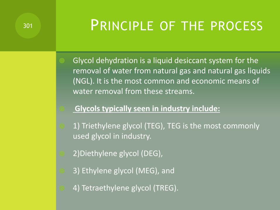
PRINCIPLE OF THE PROCESS
Glycol dehydration is a liquid desiccant system for the removal of water from natural gas and natural gas liquids (NGL). It is the most common and economic means of water removal from these streams.
Glycols typically seen in industry include:
1) Triethylene glycol (TEG), TEG is the most commonly used glycol in industry.
2)Diethylene glycol (DEG),
3) Ethylene glycol (MEG), and
4) Tetraethylene glycol (TREG).
301
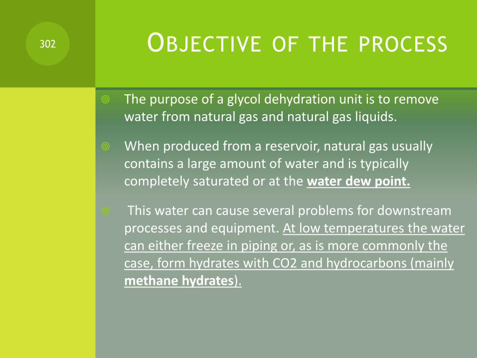
OBJECTIVE OF THE PROCESS
The purpose of a glycol dehydration unit is to remove water from natural gas and natural gas liquids.
When produced from a reservoir, natural gas usually contains a large amount of water and is typically completely saturated or at the water dew point.
This water can cause several problems for downstream processes and equipment. At low temperatures the water can either freeze in piping or, as is more commonly the case, form hydrates with CO2 and hydrocarbons (mainly methane hydrates).
302
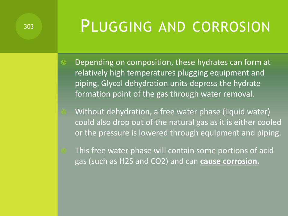
PLUGGING AND CORROSION
Depending on composition, these hydrates can form at relatively high temperatures plugging equipment and piping. Glycol dehydration units depress the hydrate formation point of the gas through water removal.
Without dehydration, a free water phase (liquid water) could also drop out of the natural gas as it is either cooled or the pressure is lowered through equipment and piping.
This free water phase will contain some portions of acid gas (such as H2S and CO2) and can cause corrosion.
303

PROCESS DESCRIPTION
Lean, water-free glycol (purity >99%) is fed to the top of an absorber (also known as a "glycol contactor") where it is contacted with the wet natural gas stream.
The glycol removes water from the natural gas by physical absorption and is carried out the bottom of the column.
Upon exiting the absorber the glycol stream is often referred to as "rich glycol". The dry natural gas leaves the top of the absorption column and is fed either to a pipeline system or to a gas plant.
Glycol absorbers can be either tray columns or packed columns.
304

After leaving the absorber, the rich glycol is fed to a flash vessel where hydrocarbon vapors are removed and any liquid hydrocarbons are skimmed from the glycol.
This step is necessary as the absorber is typically operated at high pressure and the pressure must be reduced before the regeneration step.
Due to the composition of the rich glycol, a vapor phase having a high hydrocarbon content will form when the pressure is lowered.
After leaving the flash vessel, the rich glycol is heated in a cross-exchanger and fed to the stripper (also known as a regenerator
305

The glycol stripper consists of a column, an overhead condenser, and a reboiler. The glycol is thermally regenerated to remove excess water and regain the high glycol purity.
The hot, lean glycol is cooled by cross-exchange with rich glycol entering the stripper.
It is then fed to a lean pump where its pressure is elevated to that of the glycol absorber.
The lean solvent is cooled again with a trim cooler before being fed back into the absorber.
This trim cooler can either be a cross-exchanger with the dry gas leaving the absorber or an aerial type cooler.
306

307
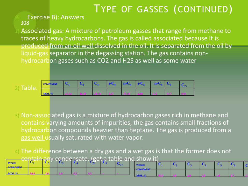
TYPE OF GASSES (CONTINUED) Exercise B): Answers
1) Associated gas: A mixture of petroleum gasses that range from methane to traces of heavy hydrocarbons. The gas is called associated because it is produced from an oil well dissolved in the oil. It is separated from the oil by liquid-gas separator in the degassing station. The gas contains non-hydrocarbon gases such as CO2 and H2S as well as some water
2) Table.
3) Non-associated gas is a mixture of hydrocarbon gases rich in methane and contains varying amounts of impurities, the gas contains small fractions of hydrocarbon compounds heavier than heptane. The gas is produced from a gas well usually saturated with water vapor.
4) The difference between a dry gas and a wet gas is that the former does not contain any condensate. (get a table and show it)
308
COMPONENT C1 C2 C3 i-C4 n-C4 i-C5 n-C5 C6 C7+
MOL % 27.52 16.34 29.18 5.37 17.18 2.18 1.72 0.47 0.04
Dry gas
COMPONENT
C1 C2 C3 C4 C5 C6 C7+
MOL % 96.0 2.0 1.0 0.5 0.5 - -
Wet gas
COMPONENT
C1 C2 C3 C4 C5 C6 C7+
MOL % 90.0 3.0 2.0 2.0 1.0 0.5 1.5

TYPE OF GASSES (CONTINUED)
Sour gas: Natural gases that are acidic. They contain significant amounts of H2S (hydrogen sulfide). According to some sources, a natural gas is considered sour if there are more than 5.7 mg of H2S per m3 of natural gas.
Lean gas: Residual gas, mainly methane and ethane that remains after the heavier hydrocarbons have been condensed in the wellhead*. When liquefied it is called LNG**.
Questions:
1) What are the components that affect the gas quality
mentioned above?***
309
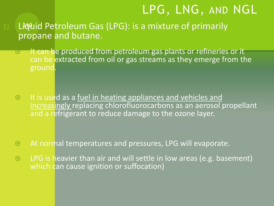
LPG, LNG, AND NGL
1) Liquid Petroleum Gas (LPG): is a mixture of primarily propane and butane.
It can be produced from petroleum gas plants or refineries or it can be extracted from oil or gas streams as they emerge from the ground.
It is used as a fuel in heating appliances and vehicles and increasingly replacing chlorofluorocarbons as an aerosol propellant and a refrigerant to reduce damage to the ozone layer.
At normal temperatures and pressures, LPG will evaporate.
LPG is heavier than air and will settle in low areas (e.g. basement) which can cause ignition or suffocation)
310
LPG, LNG, AND NGL (CONTINUED)
Assignment (LPG):
a) Find a typical composition of LPG and write it down.
b) What are the physical properties of LPG
c) Where is LPG produced in the UAE, and at what capacity.
d) What is the ratio of propane to butane in LPG.
e) At what pressure is LPG kept in Cylinders?
311

LPG, LNG, AND NGL (CONTINUED)
2) Liquid natural gas (LNG): is essentially methane that is liquefied at atmospheric pressure by cooling it down to – 260 0F.
Assignment (LNG):
Go to www.bp.com and find and print the world “gas trade movements” LNG spreadsheet and answer the following questions:
1. Which country is the largest exporter of LNG in the world?
2. Which country is the largest exporter in the Arab world?
3. Try to find how much LNG did the UAE export?
312
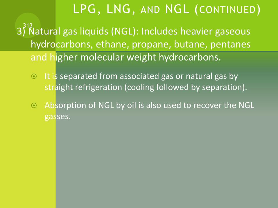
LPG, LNG, AND NGL (CONTINUED)
3) Natural gas liquids (NGL): Includes heavier gaseous hydrocarbons, ethane, propane, butane, pentanes and higher molecular weight hydrocarbons.
It is separated from associated gas or natural gas by straight refrigeration (cooling followed by separation).
Absorption of NGL by oil is also used to recover the NGL gasses.
313

Exercise:
1. Which country has the largest gas reserves, (if possible give values in million ft3 )
2. Which gulf country has the largest reserves of natural gas (if possible how much gas in ft3)
3. Which country has the largest amount of natural gas (if possible how much gas in ft3)
4. Which country consumes the largest amount of natural gas and how much?
5. Which country in the middle east consumes the largest amount of natural gas.
314
Gas processing by countries and regions*

CALORIFIC VALUE
315

ENERGY (OR HEAT) AND SPECIFIC HEAT (QUICK REVIEW)
Example:
Taking a bath might use about 95kg of
water. How much energy (in cal) is needed
to heat the water* from a cold 15 0C to a
warm 40 0C.**
(Do this simple calculation?)
316

ENERGY (OR HEAT) AND SPECIFIC HEAT (QUICK
REVIEW)(CONTINUE) 1 calorie is the amount of heat needed to raise the temperature of 1g of water by
1oC*. See**
Calorie is the metric unit of energy (or heat);
1 cal = 4.184 J (SI unit)
Specific heat is the amount of heat needed to raise the temperature of 1g of aspecific substance by 1oC*.
Specific heat = Cal / (g . oC)
Recall:
317
CALORIFIC VALUE (CV)
Calorific value of natural gas is the “heating value” (amount of heat that natural gas gives off) when natural gas is burnt.
The Calorific value is a characteristic of each substance (what does this mean?)
Calorific values are measured in units of energy per unit of the substances (usually mass or volume).
In the metric system common units of calorific values are kJ/kg and MJ/kg or kJ/m3 and MJ/m3….etc….
318

CALORIFIC VALUE (CV) [CONTINUED]
Why is the Calorific value important? (next page)
319

CALORIFIC VALUE (CV) [CONTINUED]
The calorific value of a fuel is important because it is important to note how much heat will be provided when a specific fuel is burnt (in boilers, heaters..etc..). WHY?*
Basically it is a measure of the heat liberated on burning a unit mass or volume of the fuel.
Therefore when natural gas is sold, the heating (Calorific Value) is important. There is usually a minimum heating value of the natural gas (in MJ/m3) to meet the gas sales contracts.
When heavy hydrocarbons are removed from natural gas, the heating value in MJ/m3 is actually reduced. WHY?
Also when there is an excess of nitrogen and/or carbon dioxide in natural
320

CALORIFIC VALUE (CV) [CONTINUED]
Note that:
CV is the negative of the standard heat of combustion (i.e. the heat liberated on burning a unit mass of the fuel).
Typical heating values,
Gasoline 44000 kJ/kg 19000 Btu/lbm
Natural gas 54000 kJ/kg 23000 Btu/lbm
321
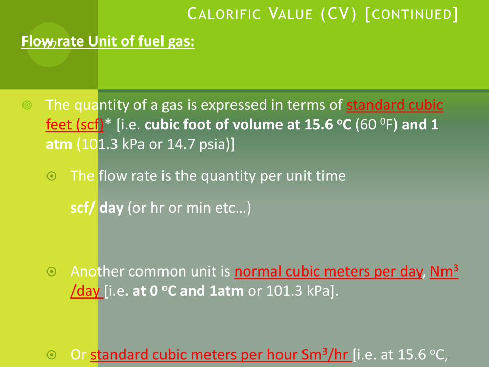
CALORIFIC VALUE (CV) [CONTINUED]
Flow rate Unit of fuel gas:
The quantity of a gas is expressed in terms of standard cubic feet (scf)* [i.e. cubic foot of volume at 15.6 oC (60 0F) and 1 atm (101.3 kPa or 14.7 psia)]
The flow rate is the quantity per unit time
scf/ day (or hr or min etc…)
Another common unit is normal cubic meters per day, Nm3
/day [i.e. at 0 oC and 1atm or 101.3 kPa].
Or standard cubic meters per hour Sm3/hr [i.e. at 15.6 oC, and 1 atm or 101.3 kPa].
322
CALORIFIC VALUE (CV) [CONTINUED]
Exercise 1: Flow rate
If the flow rate of a gas 3000 Sm3/hr, what
will the flow rate be in:
a) Nm3/day
323

CALORIFIC VALUE (CV) [CONTINUED]
Exercise 2 : Flow rate
a) If the flow rate of a gas is 3000 Sm3/hr, what will the flow rate be in scf/day?
b) A plant flare is measured as 3000 Sm3/hr. If the gas is flaring at an out side temperature of 35oC and 1 atm (i.e. actual condition), what is the volumetric flow rate is in m3/day.
324

CALORIFIC VALUE (CV) [CONTINUED]
Class Exercise*:
A gas plant flares 3700 Sm3/hr of gas, at 35 0C and 1 atm.
If the flared gas has a heating value (i.e. CV) of 8000kJ/m3,
how much heat energy is wasted per year?
325

CALORIFIC VALUE (CV) [CONTINUED]
Standard Temperature and Pressure (STP):
It is a standard set of conditions for experimental measurement (i.e. at 0 oC and 1 atm)
At standard temperature and pressure, one mole of any gas (6.02 x 10²³ particles) has a volume of 22.4 L. In other words;
22.4L / mol
326
CALORIFIC VALUE (CV) [CONTINUED]
Simple example:
Use the standard molar volume of a gas at STP to find how
many moles of air at STP are in a room measuring
4.11m by 5.36m by 2.58m.*
Note: recall: At standard temperature and pressure, one
mole of any gas (6.02 x 10²³ particles) has a volume of
22.4 L. In other words; 22.4L / mol
327
CALORIFIC VALUE (CV) [CONTINUED]
CV for different components can be found in tables or calculated using the heat of reaction (i.e. combustion reaction) based on heat of formation.
Keep in mined that CV is the same as the heat of combustion per mol.
The calorific value for a gas mixture is calculated as follows:
328
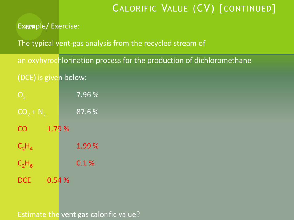
CALORIFIC VALUE (CV) [CONTINUED]
Example/ Exercise:
The typical vent-gas analysis from the recycled stream of
an oxyhyrochlorination process for the production of dichloromethane
(DCE) is given below:
O2 7.96 %
CO2 + N2 87.6 %
CO 1.79 %
C2H4 1.99 %
C2H6 0.1 %
DCE 0.54 %
Estimate the vent gas calorific value?
329
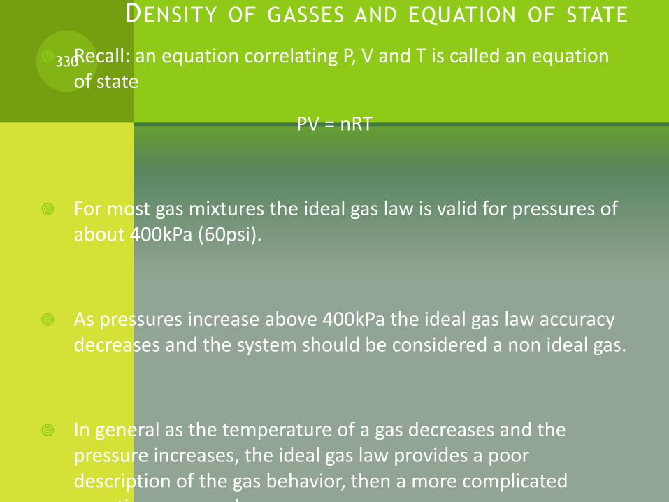
DENSITY OF GASSES AND EQUATION OF STATE
Recall: an equation correlating P, V and T is called an equation of state
PV = nRT
For most gas mixtures the ideal gas law is valid for pressures of about 400kPa (60psi).
As pressures increase above 400kPa the ideal gas law accuracy decreases and the system should be considered a non ideal gas.
In general as the temperature of a gas decreases and the pressure increases, the ideal gas law provides a poor description of the gas behavior, then a more complicated equations are used.
330

DENSITY OF GASSES AND EQUATION OF STATE (CONTINUED)Non-ideal equations of state:
1) Compressibility equation of state
PV=znRT
2) Cubic Equations of State;
Van der waals
Benedict-webb-Rubin (BWR)
Redlich-Kwaong (RK)
Peng-Robinson (PR)
(See *)
331
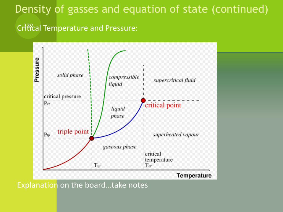
Critical Temperature and Pressure:
Explanation on the board…take notes
332
Density of gasses and equation of state (continued)
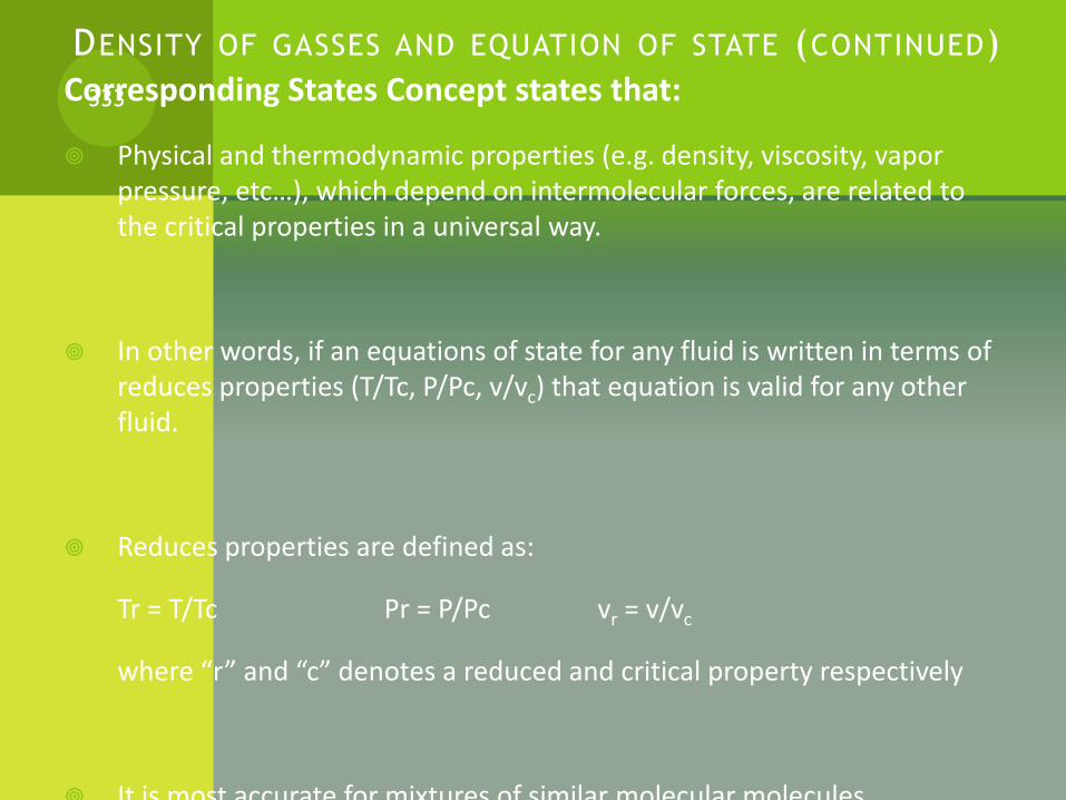
DENSITY OF GASSES AND EQUATION OF STATE (CONTINUED)
Corresponding States Concept states that:
Physical and thermodynamic properties (e.g. density, viscosity, vapor pressure, etc…), which depend on intermolecular forces, are related to the critical properties in a universal way.
In other words, if an equations of state for any fluid is written in terms of reduces properties (T/Tc, P/Pc, v/vc) that equation is valid for any other fluid.
Reduces properties are defined as:
Tr = T/Tc Pr = P/Pc vr = v/vc
where “r” and “c” denotes a reduced and critical property respectively
It is most accurate for mixtures of similar molecular molecules.
333

DENSITY OF GASSES AND EQUATION OF STATE (CONTINUED) An example of how the corresponding state concept is most accurate for
mixtures of similar molecular molecules:
Figures (a) shows the vapor
pressure of methane and propane
Figure (b) shows the reduced vapor
pressure of methane and propane.
In figure (b) Notice how the two
reduced vapor pressure curves are
almost identical
If the corresponding states theory
were perfectly valid, these curves
334
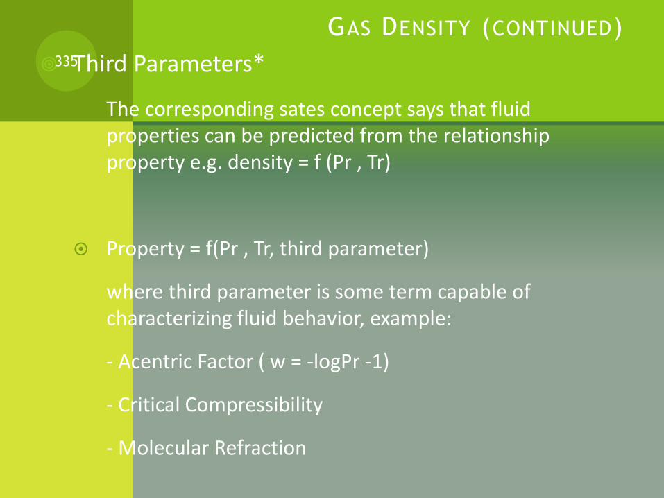
GAS DENSITY (CONTINUED)
Third Parameters*
The corresponding sates concept says that fluid properties can be predicted from the relationship property e.g. density = f (Pr , Tr)
Property = f(Pr , Tr, third parameter)
where third parameter is some term capable of characterizing fluid behavior, example:
- Acentric Factor ( w = -logPr -1)
- Critical Compressibility
- Molecular Refraction
335
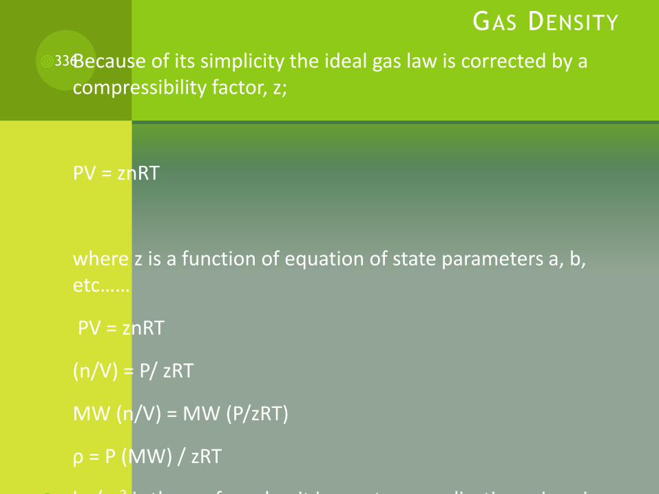
GAS DENSITY
Because of its simplicity the ideal gas law is corrected by a compressibility factor, z;
PV = znRT
where z is a function of equation of state parameters a, b, etc……
PV = znRT
(n/V) = P/ zRT
MW (n/V) = MW (P/zRT)
ρ = P (MW) / zRT
kg/m3 is the preferred unit in most gas applications since in
336

GAS DENSITY (CONTINUED)
Katz Correlation and Kay’s Rule;
This is a method for finding z.
It assumes that [(property) e.g. density = f (Pr , Tr) ] is valid.
Fig 3.2 (P56) is the correlation prepared by Katz, for lean, sweet natural gas.
The values of P’c and T’c may be found from Kay’s Rule. This rules states that:
and
where;
yi = mole fraction of each component
337

GAS DENSITY (CONTINUED)
Assignment 1: Gas Density
Calculate the density for the gas shown in the
table, at 13.94 Mpa [ 2021 psia] and 331
K [596 oC], using Kays Rule and the given Figures
and tables.
338
Comp yiN2 0.0046
CO2 0.003H2S 0.1438C1 0.8414C2 0.0059C3 0.0008iC4 0.0003nC4 0.0002
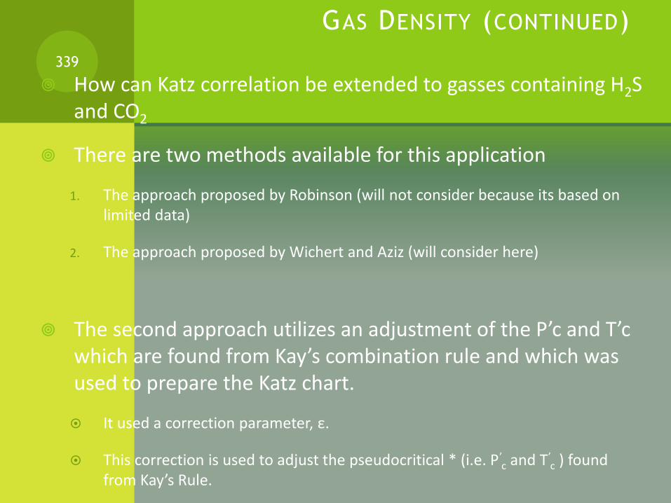
GAS DENSITY (CONTINUED)
How can Katz correlation be extended to gasses containing H2S and CO2
There are two methods available for this application
1. The approach proposed by Robinson (will not consider because its based on limited data)
2. The approach proposed by Wichert and Aziz (will consider here)
The second approach utilizes an adjustment of the P’c and T’c which are found from Kay’s combination rule and which was used to prepare the Katz chart.
It used a correction parameter, ε.
This correction is used to adjust the pseudocritical * (i.e. P’c and T’
c ) found from Kay’s Rule.
339

GAS DENSITY (CONTINUED)
The equation for making the adjustment is:340
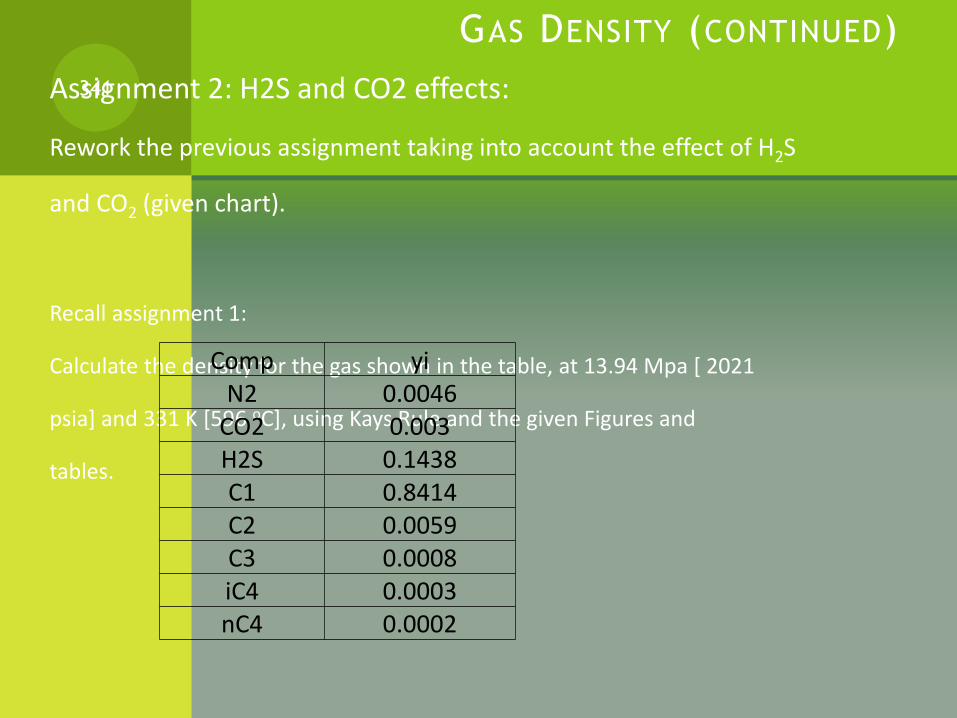
GAS DENSITY (CONTINUED)
Assignment 2: H2S and CO2 effects:
Rework the previous assignment taking into account the effect of H2S
and CO2 (given chart).
Recall assignment 1:
Calculate the density for the gas shown in the table, at 13.94 Mpa [ 2021
psia] and 331 K [596 oC], using Kays Rule and the given Figures and
tables.
341
Comp yiN2 0.0046
CO2 0.003H2S 0.1438C1 0.8414C2 0.0059C3 0.0008iC4 0.0003nC4 0.0002

L IQUID DENSITY
Specific gravity, by definition, was the density of a liquid divided by the density of pure water.
In new SI standards, specific gravity is replaced by the term relative density (which is the density of a substance relative to a specific reference, not necessarily water)
At 15 oC [59 oF] the density of water is 1.00095 g/cm3.
For engineering calculations 1.0 g/cm3 is sufficient at any ambient air temperature. In other word the error in using 1.0 g/cm3 is very small.
For this case, the density, ρ, for any fluid is represented as:
(g/cm3) = γ (kg/m3) = 1000γ (lb/ft3) = 62.4γ
342
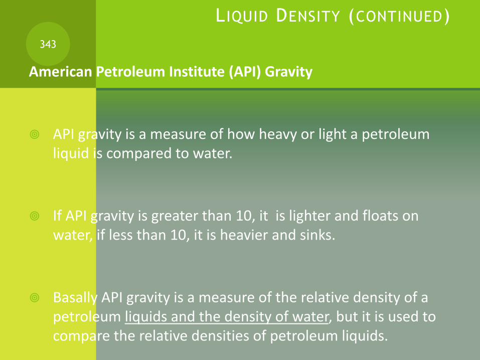
L IQUID DENSITY (CONTINUED)
American Petroleum Institute (API) Gravity
API gravity is a measure of how heavy or light a petroleum liquid is compared to water.
If API gravity is greater than 10, it is lighter and floats on water, if less than 10, it is heavier and sinks.
Basally API gravity is a measure of the relative density of a petroleum liquids and the density of water, but it is used to compare the relative densities of petroleum liquids.
343
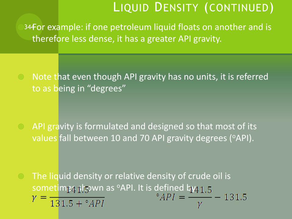
LIQUID DENSITY (CONTINUED)
For example: if one petroleum liquid floats on another and is therefore less dense, it has a greater API gravity.
Note that even though API gravity has no units, it is referred to as being in “degrees”
API gravity is formulated and designed so that most of its values fall between 10 and 70 API gravity degrees (oAPI).
The liquid density or relative density of crude oil is sometimes shown as oAPI. It is defined by:
or
344
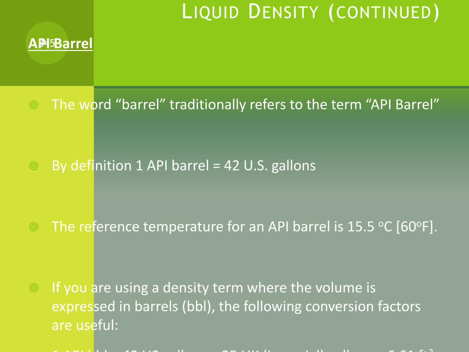
LIQUID DENSITY (CONTINUED)
API Barrel
The word “barrel” traditionally refers to the term “API Barrel”
By definition 1 API barrel = 42 U.S. gallons
The reference temperature for an API barrel is 15.5 oC [60oF].
If you are using a density term where the volume is expressed in barrels (bbl), the following conversion factors are useful:
1 API bbl = 42 US gallons = 35 UK (Imperial) gallons = 6.61 ft3
345
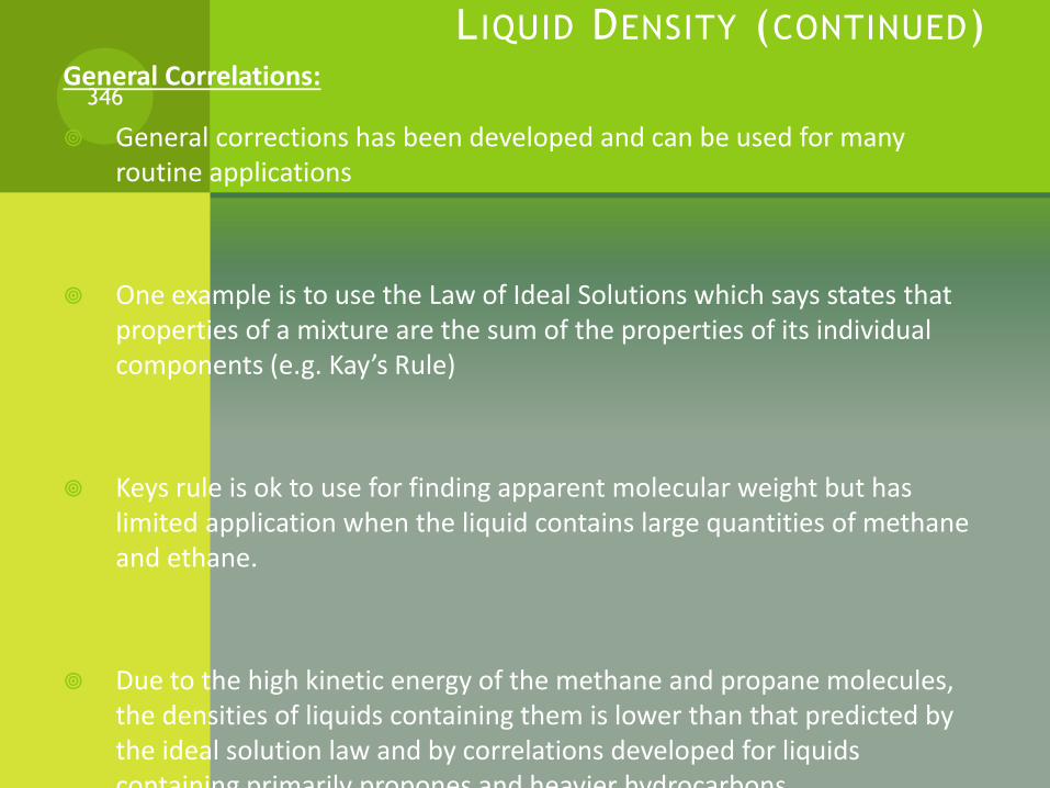
L IQUID DENSITY (CONTINUED)General Correlations:
General corrections has been developed and can be used for many routine applications
One example is to use the Law of Ideal Solutions which says states that properties of a mixture are the sum of the properties of its individual components (e.g. Kay’s Rule)
Keys rule is ok to use for finding apparent molecular weight but has limited application when the liquid contains large quantities of methane and ethane.
Due to the high kinetic energy of the methane and propane molecules, the densities of liquids containing them is lower than that predicted by the ideal solution law and by correlations developed for liquids containing primarily propones and heavier hydrocarbons.
346
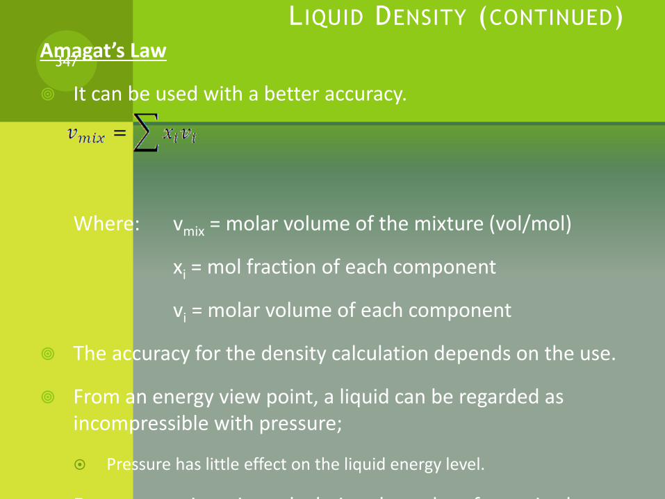
L IQUID DENSITY (CONTINUED)
Amagat’s Law
It can be used with a better accuracy.
Where: vmix = molar volume of the mixture (vol/mol)
xi = mol fraction of each component
vi = molar volume of each component
The accuracy for the density calculation depends on the use.
From an energy view point, a liquid can be regarded as incompressible with pressure;
Pressure has little effect on the liquid energy level.
For most engineering calculation the order of magnitude
347
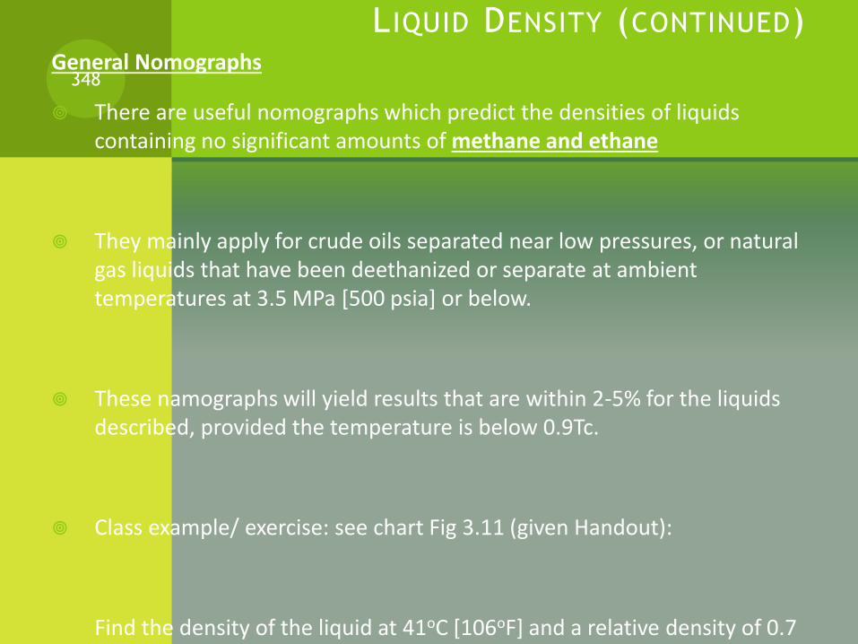
L IQUID DENSITY (CONTINUED)General Nomographs
There are useful nomographs which predict the densities of liquids containing no significant amounts of methane and ethane
They mainly apply for crude oils separated near low pressures, or natural gas liquids that have been deethanized or separate at ambient temperatures at 3.5 MPa [500 psia] or below.
These namographs will yield results that are within 2-5% for the liquids described, provided the temperature is below 0.9Tc.
Class example/ exercise: see chart Fig 3.11 (given Handout):
Find the density of the liquid at 41oC [106oF] and a relative density of 0.7 and Kw of 12.0
348

L IQUID DENSITY (CONTINUED)Corresponding States Method.
Several corresponding states models have been proposed for the prediction of liquid densities. Three methods that are widely used in the industry follows:
1- API Method
2- Modified Rackett Equation
3- Hankinson-Brobst-Thomson [COSTALD]
349

L IQUID DENSITY (CONTINUED)1) API Method:
Of the motioned three methods, only method number one involves hand calculation.
The API method can be used to predict densities of hydrocarbon liquids when the mixture is composed of molecules of similar size and shape. E.g C3-C4, C5-C6, etc..
It is less accurate for mixtures containing a wide range of molecules, e.g C1-C7
Figure 3.14 (handout) is a plot of C, a density factor as a function of Pr and Tr.
The density factor is used to correct the known density, ρ1, at one condition to a density, ρ2 , at another condition using the equation:
Equation (3.20)
350

L IQUID DENSITY (CONTINUED)
Assignment 3:
Estimate the density of an Epmix (80% C2, 20% C3) at
10000 kPa [1450 psia] and 10oC [50 oF] using Figure 3.14
(handout), other tables, and the help of equations, if needed:
Amagat’s Law
Kay’s rule
351
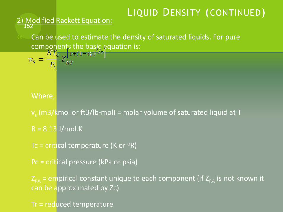
L IQUID DENSITY (CONTINUED)2) Modified Rackett Equation:
Can be used to estimate the density of saturated liquids. For pure components the basic equation is:
Where;
vs (m3/kmol or ft3/lb-mol) = molar volume of saturated liquid at T
R = 8.13 J/mol.K
Tc = critical temperature (K or oR)
Pc = critical pressure (kPa or psia)
ZRA = empirical constant unique to each component (if ZRA is not known it can be approximated by Zc)
Tr = reduced temperature
352
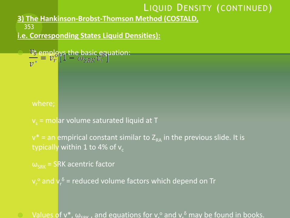
L IQUID DENSITY (CONTINUED)3) The Hankinson-Brobst-Thomson Method (COSTALD,
i.e. Corresponding States Liquid Densities):
It employs the basic equation:
where;
vs = molar volume saturated liquid at T
v* = an empirical constant similar to ZRA in the previous slide. It is typically within 1 to 4% of vc
ωSRK = SRK acentric factor
vro and vr
δ = reduced volume factors which depend on Tr
Values of v*, ωSRK , and equations for vro and vr
δ may be found in books.
353
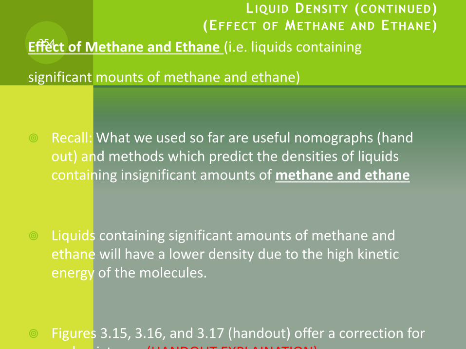
L IQUID DENSITY (CONTINUED)
(EFFECT OF METHANE AND ETHANE)
Effect of Methane and Ethane (i.e. liquids containing
significant mounts of methane and ethane)
Recall: What we used so far are useful nomographs (hand out) and methods which predict the densities of liquids containing insignificant amounts of methane and ethane
Liquids containing significant amounts of methane and ethane will have a lower density due to the high kinetic energy of the molecules.
Figures 3.15, 3.16, and 3.17 (handout) offer a correction for such mixtures. (HANDOUT EXPLAINATION)
354
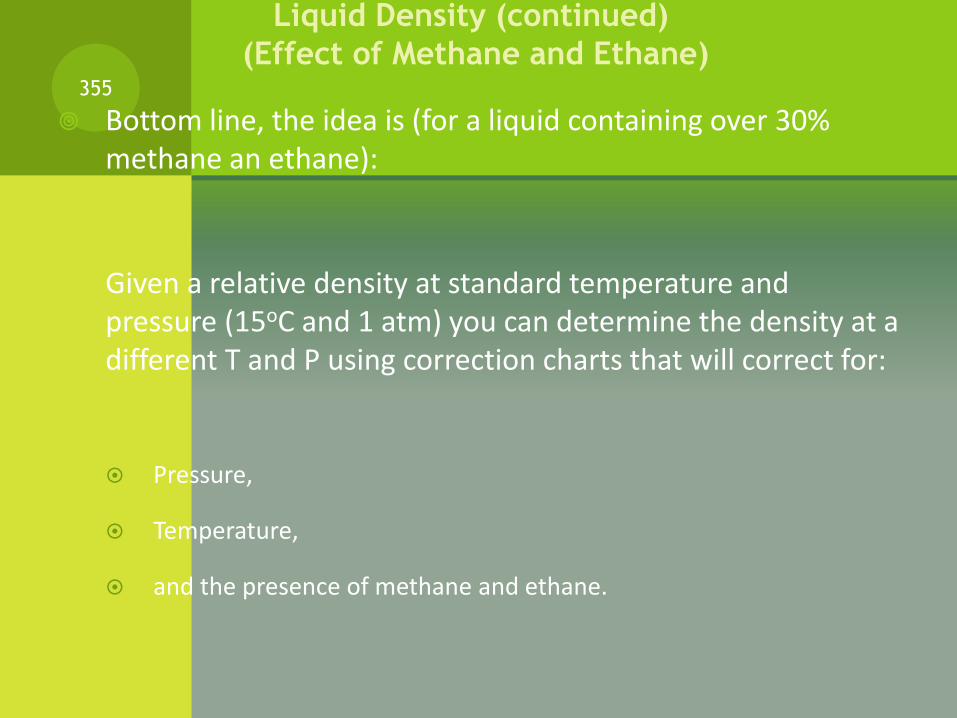
Bottom line, the idea is (for a liquid containing over 30% methane an ethane):
Given a relative density at standard temperature and pressure (15oC and 1 atm) you can determine the density at a different T and P using correction charts that will correct for:
Pressure,
Temperature,
and the presence of methane and ethane.
355
Liquid Density (continued)
(Effect of Methane and Ethane)
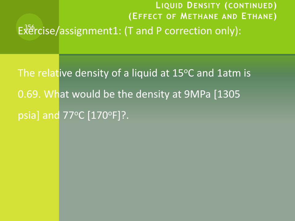
L IQUID DENSITY (CONTINUED)
(EFFECT OF METHANE AND ETHANE)
Exercise/assignment1: (T and P correction only):
The relative density of a liquid at 15oC and 1atm is
0.69. What would be the density at 9MPa [1305
psia] and 77oC [170oF]?.
356

L IQUID DENSITY (CONTINUED)
(EFFECT OF METHANE AND ETHANE)
Now correct for methane and ethane (chart 3.16):
Note that for a liquid mixture, two calculation steps
need to be followed, we need to calculate:
1. The weight percent ethane in the “ethane-mixture-plus-fraction”
2. The weight percent methane in the total liquid
(WHY?*)
357
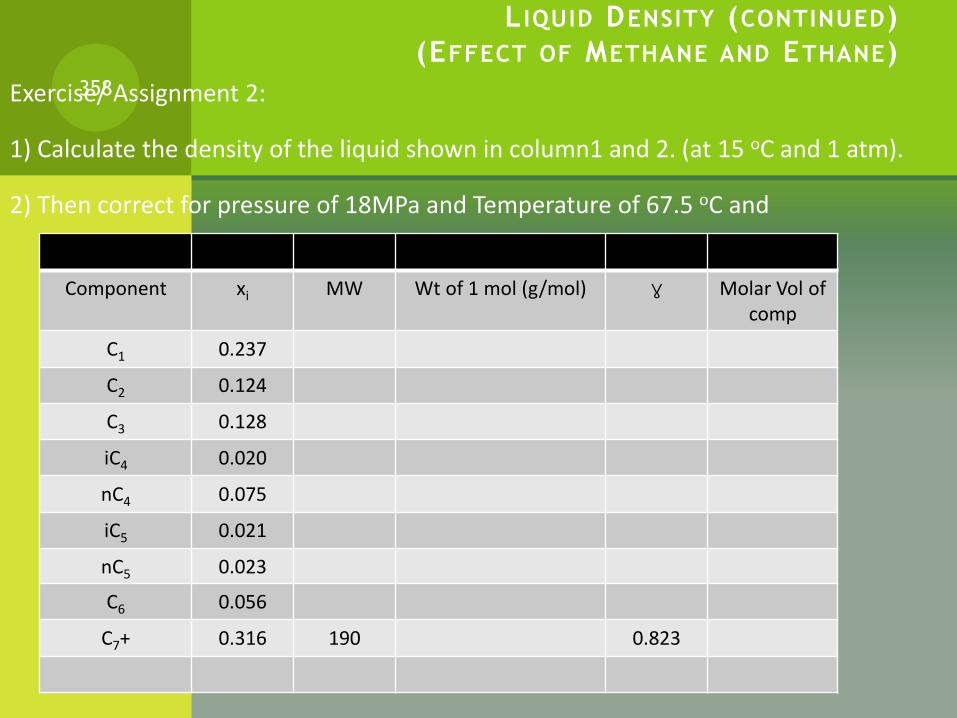
L IQUID DENSITY (CONTINUED)
(EFFECT OF METHANE AND ETHANE)
Exercise/ Assignment 2:
1) Calculate the density of the liquid shown in column1 and 2. (at 15 oC and 1 atm).
2) Then correct for pressure of 18MPa and Temperature of 67.5 oC and
358
Component xi MW Wt of 1 mol (g/mol) γ Molar Vol of comp
C1 0.237
C2 0.124
C3 0.128
iC4 0.020
nC4 0.075
iC5 0.021
nC5 0.023
C6 0.056
C7+ 0.316 190 0.823

STOP359
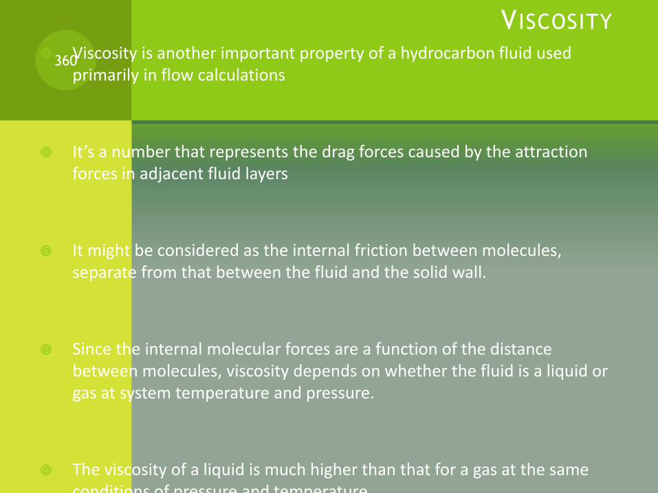
V ISCOSITY
Viscosity is another important property of a hydrocarbon fluid used primarily in flow calculations
It’s a number that represents the drag forces caused by the attraction forces in adjacent fluid layers
It might be considered as the internal friction between molecules, separate from that between the fluid and the solid wall.
Since the internal molecular forces are a function of the distance between molecules, viscosity depends on whether the fluid is a liquid or gas at system temperature and pressure.
The viscosity of a liquid is much higher than that for a gas at the same conditions of pressure and temperature.
360

V ISCOSITY
Units of Viscosity
The basic petroleum viscosity unit has been the poise, or more commonly the centipoise.
The poise is a measure of absolute (dynamic) viscosity.
It is a derived metric unit;
1 poise = 1 (dyne)(sec) per cm2.
1 centipoise (cp) = 0.01 dyne.s/cm2 = 0.001 Pa.s
The kinematic viscosity is the absolute viscosity divided by density. And the usual unit is the “stoke” or “centistokes”
1 centistoke = 0.01 cm2/s = 1.0 X 10⁻⁶ m2/sec
361

GAS VISCOSITY
The viscosity of natural gas at 100kPa [14.5psia] may be estimated from Figure 3.18 (handout given).
Corrections are provided for N2. CO2 and H2S.
The molecular weight is found using Kay’s Rule or from the relative density at standard conditions.
Gas viscosity can be estimated for a mixture from the following equation:
(this equation agrees with Figure 3.18 within reason)
where:
µm = mixture viscosity
µ = viscosity of each component
362

GAS V ISCOSITY (CONTINUED)
The correction for temperature and pressure is made from Figure 3.19 (Handout) where Tr and Pr are found from the critical values obtained by Kay’s Rule.
In Figure 3.19 the y axis (µ/µ1) is the ratio of the viscosity at actual conditions (µ) divided by the viscosity (µ1) found from Figure 3.18.
Notice that gas viscosity is very low which indicates the large distance between molecules.
There are also other reference books that present other high pressure viscosity correlations.
363
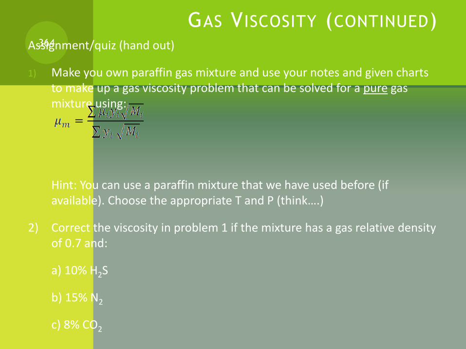
GAS VISCOSITY (CONTINUED)Assignment/quiz (hand out)
1) Make you own paraffin gas mixture and use your notes and given charts to make up a gas viscosity problem that can be solved for a pure gas mixture using:
Hint: You can use a paraffin mixture that we have used before (if available). Choose the appropriate T and P (think….)
2) Correct the viscosity in problem 1 if the mixture has a gas relative density of 0.7 and:
a) 10% H2S
b) 15% N2
c) 8% CO2
364
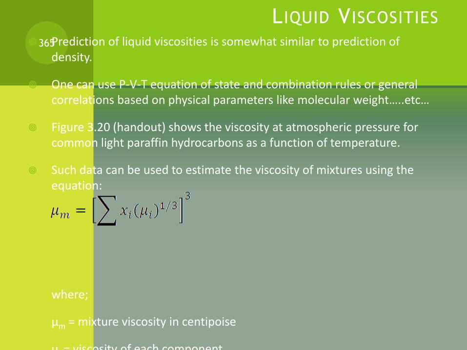
LIQUID VISCOSITIES
Prediction of liquid viscosities is somewhat similar to prediction of density.
One can use P-V-T equation of state and combination rules or general correlations based on physical parameters like molecular weight…..etc…
Figure 3.20 (handout) shows the viscosity at atmospheric pressure for common light paraffin hydrocarbons as a function of temperature.
Such data can be used to estimate the viscosity of mixtures using the equation:
where;
µm = mixture viscosity in centipoise
µi = viscosity of each component
365
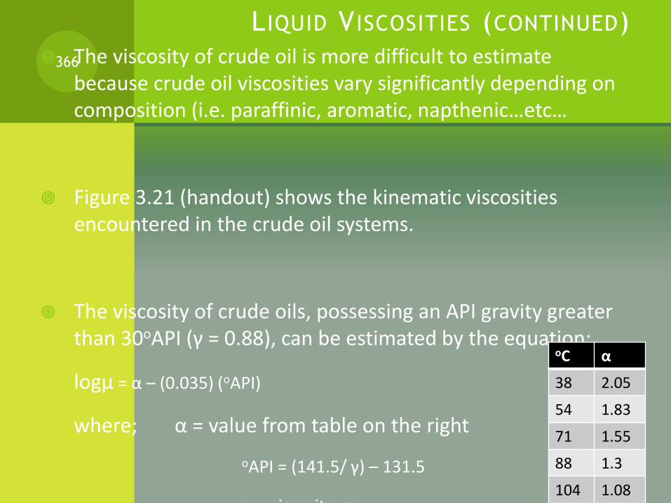
L IQUID V ISCOSITIES (CONTINUED)
The viscosity of crude oil is more difficult to estimate because crude oil viscosities vary significantly depending on composition (i.e. paraffinic, aromatic, napthenic…etc…
Figure 3.21 (handout) shows the kinematic viscosities encountered in the crude oil systems.
The viscosity of crude oils, possessing an API gravity greater than 30oAPI (γ = 0.88), can be estimated by the equation:
logµ = α – (0.035) (oAPI)
where; α = value from table on the right
oAPI = (141.5/ γ) – 131.5
µ = viscosity, cp
366
oC α
38 2.05
54 1.83
71 1.55
88 1.3
104 1.08
L IQUID V ISCOSITIES (CONTINUED)
Correlations for the prediction of the viscosity of liquids with known composition posses a general reliability of 13-15%.
This range offers no particular problem in the type of calculations where viscosity is used.
For crude oils the viscosity should be determined by laboratory tests, particularly for separator design.
367

SURFACE TENSION A molecule on the surface of a liquid is subject to an inward force as a
result of the attraction between molecules.
This surface molecule tends to adjust itself to a minimum surface area causing the droplets to assume a spherical shape.
Work is necessary to extend this surface or to bring molecules from the bulk of the liquid into the surface.
This work has been expressed traditionally in ergs/cm2 and is measured of what is called free surface energy.
If one thinks of the attractive forces as a film over the liquid surface one can speak of the result as surface tension, expressed as dynes/cm.
368
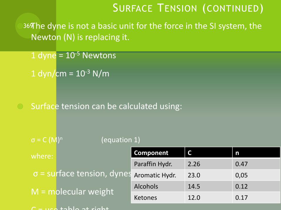
SURFACE TENSION (CONTINUED)
The dyne is not a basic unit for the force in the SI system, the Newton (N) is replacing it.
1 dyne = 10-5 Newtons
1 dyn/cm = 10-3 N/m
Surface tension can be calculated using:
σ = C (M)n (equation 1)
where:
σ = surface tension, dynes/cm
M = molecular weight
C = use table at right
369
Component C n
Paraffin Hydr. 2.26 0.47
Aromatic Hydr. 23.0 0,05
Alcohols 14.5 0.12
Ketones 12.0 0.17
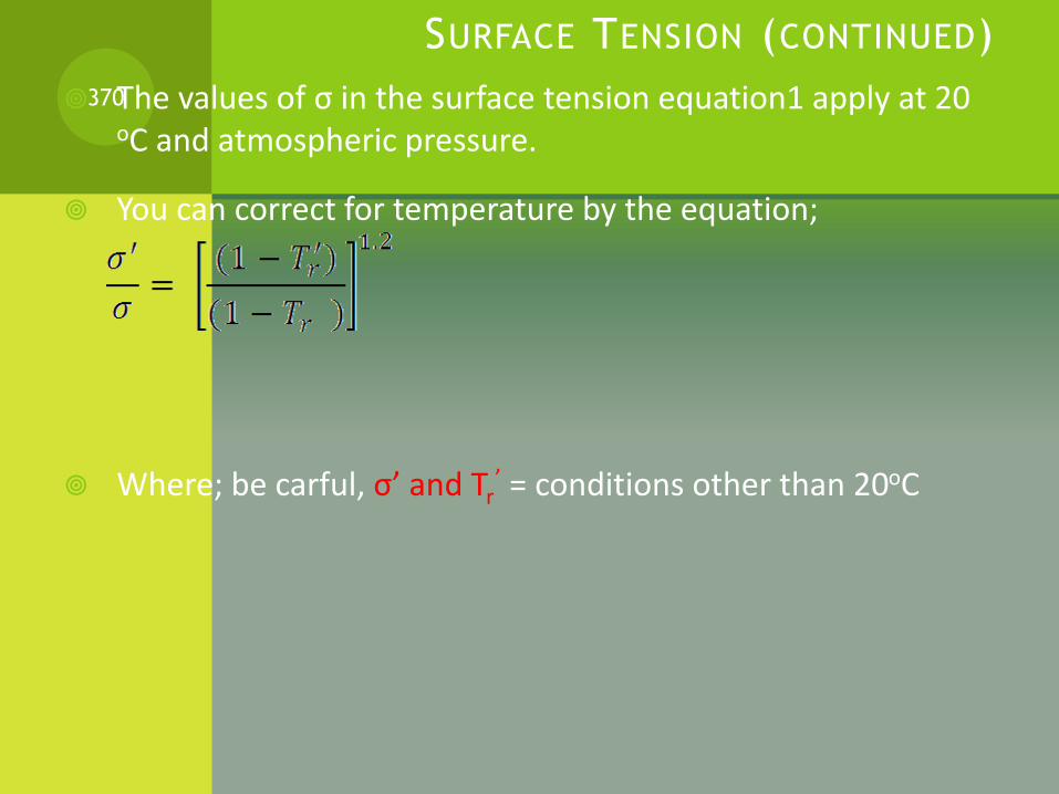
SURFACE TENSION (CONTINUED)
The values of σ in the surface tension equation1 apply at 20 oC and atmospheric pressure.
You can correct for temperature by the equation;
Where; be carful, σ’ and Tr’ = conditions other than 20oC
370
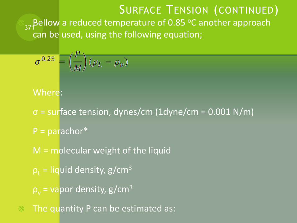
SURFACE TENSION (CONTINUED) Bellow a reduced temperature of 0.85 oC another approach
can be used, using the following equation;
Where:
σ = surface tension, dynes/cm (1dyne/cm = 0.001 N/m)
P = parachor*
M = molecular weight of the liquid
ρL = liquid density, g/cm3
ρv = vapor density, g/cm3
The quantity P can be estimated as:
P = 40 + (2.6) (MW) for parrafins, and mixtures having a mol wt
371

SURFACE TENSION (CONTINUED)
Surface tension is affected by the temperature and the composition of the liquid and vapor around a drop.
Pressure has an indirect effect only, due to its effect on composition and density.
There are other references in the literature that present methods for estimating the surface tension of mixtures
372
BUBBLE POINT AND DEW POINT
Exercise 1
Find the bubble point and the dew point and the corresponding vapor
and liquid compositions for a mixture of 33 mol% n-hexane, 37 mol% n-heptane, and 30% n-octane. The total pressure is 1.2 atm.
373
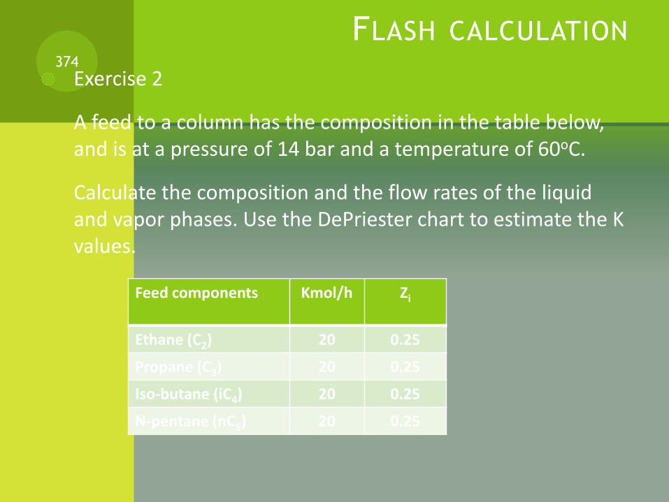
FLASH CALCULATION
Exercise 2
A feed to a column has the composition in the table below, and is at a pressure of 14 bar and a temperature of 60oC.
Calculate the composition and the flow rates of the liquid and vapor phases. Use the DePriester chart to estimate the K values.
374
Feed components Kmol/h Zi
Ethane (C2) 20 0.25
Propane (C3) 20 0.25
Iso-butane (iC4) 20 0.25
N-pentane (nC5) 20 0.25

GAS PROCESSING PLANT DIAGRAM375
CRUDE OIL/GAS SEPARATION
This section of the processing plant is used to separate the associated gas from the crude oil (i.e. degassing).
Large separators are used to separate the gas from the oil usually at different pressures.
This is the first stage of gas processing.
376

GAS CONDITIONING FOR PROCESSING
This section of the Gas Processing Plant is used to remove the impurities such as:
a) water,
b) Sulfur compounds: H2S, CS, COS, mercaptans* (RHS), etc…
c) CO2
d) N2
e) Hg
f) Solids – hydrates, asphaltenes**, dust, etc..
377
GAS CONDITIONING FOR PROCESSING (CONTINUED)
a) Removal of water is termed gas dehydration and several processes are used. The most common are absorption, adsorption, condensation, and others (membrane, CaCl2, etc…)
In the absorption process, highly concentrated glycol solutions (triethylene glycol, TEG, is the most common) are used to physically absorb the water from the gas. This process is simple and the most widely used.
The adsorption process utilizes a solid desiccant* such as silica gel, alumina or molecular sieve (zeolite) to physically adsorb the water from the gas. It is used when very low (< 1ppm) effluent water contents are required.
378
GAS CONDITIONING FOR PROCESSING (CONTINUED) The condensation process is integrated with the refrigeration
module for NGL extraction. Water condenses as the gas is cooled. In order to prevent hydrate formation, an inhibitor such as monoethylene glycol (MEG) or methanol is injected into the gas.
Membranes utilize a semipermeable polymer which allows certain molecules (e.g. H2S, H2O, and CO2) to permeate (penetrate) more rapidly than others (e.g. CH4, C2H6, etc..). Note that partial pressure is the driving force for permeation. For example if the partial pressure of a component in the permeate stream is less than that in the feed stream the component will pass through the membrane**
Calcium chloride, CaCl2, can also be used to dehydrate natural gas. It will combine with water to form a brine*** which is removed for disposal. This method is limited to small volume remote applications.
379
GAS CONDITIONING FOR PROCESSING (CONTINUED)
b) and c) Removal of H2S and CO2 from natural gas is called sweetening. In general these processes can be categorized as follow:
Chemical absorption – amines, potassium carbonate, etc..
Process: Amine based solvent is the most widely used for both H2S and CO2 removal. Chemical Solvents Processes
These processes utilize a solvent, either an alkanoamine or an alkali-salt (hot carbon process) in an aqueous solution.
These solutions react with the acid gas to form a chemical bond which is broken in the regenerator at elevated temperatures and reduced pressures.
380
GAS CONDITIONING FOR PROCESSING (CONTINUED) Physical absorption
More economical when H2S and CO2 concentrations are high.
Physical Solvent Processes
Acid gas removal by physical solvents is based on physical absorption of the acid gas component.
The solubility of a gas in any liquid is relatively low, therefore, a high sour gas partial pressure is required.
The higher the partial pressure of the sour gas, the more readily it is absorbed in the solvent, to achieve adequate acid gas loading.
Physical solvent processes are typically limited to applications requiring bulk removal where the acid gas partial are very high.
An example of a commercial process employing physical absorption is the
use of Selexol (Dimethyl Ether of Polyethelene Glycol) as a solvent.
381
GAS CONDITIONING FOR PROCESSING (CONTINUED)
Solid bed – molecular sieve*, iron sponge, zinc oxide, etc.
Limited to H2S removal and are competitive when concentrations are less than 1000ppm
Other – direct conversion, membranes, extractive distillation, etc.
Direct conversion processes are applied for H2S removal and convert the H2S directly to elemental sulfur.
Membranes and extractive distillation are applied for CO2
removal.
d) Nitrogen removal from natural gas is achieved by *cryogenic fractionation from methane.
Operating temperatures can vary with pressure but can be as low as -185 oC [-300 oF]
382
GAS CONDITIONING FOR PROCESSING (CONTINUED)
e) Mercury (Hg) removal from natural gas is often necessary when aluminum heat exchangers and equipment are used in the gas processing module.
The removal is typically done by passing the gas through a bed of sulfur-impregnated activated charcoal or alumina where the mercury reacts to form mercuric sulfide HgS*.
Required effluent Hg levels depend on the temperature and pressure of the NGL extraction process, but very low temperature processes ( < -100oC or -148oF), 10ng/Nm3 is a common standard.
383

NGL EXTRACTION
NGL consists of hydrocarbon components in a produced gas stream which can be extracted and sold.
This section of the plant is used to remove the heavy hydrocarbons from the natural gas by liquefying them.
By removing the heavy hydrocarbons the hydrocarbon dew point of the natural gas is controlled to meet specification.
384

NGL EXTRACTION (CONTINUED)NGL Assignment1: Answer the question given in the handout.385
NGL STABILIZATION Once the NGL has been extracted from the gas, it must be stabilized to
meet sales specifications.
These specifications can vary significantly depending upon the end markets and transportation methods.
In some cases the NGL product is a stabilized condensate consisting only of C5+ having a vapor pressure less than 100kPa [14.4 psia]
In other cases the NGL product is a C4+ mixture which can be “spiked” into a crude oil stream for sale.
In deep NGL recovery plants, the NGL product is more likely a C2+ or C3+ product which may be transported to a fractionation plant for product separation, sale and distribution.
386
NGL STABILIZATION (CONTINUED)
Basically this section of the gas processing plant is used to remove the light hydrocarbons (methane and ethane) from the NGL mixture.
If the methane and ethane are not removed from the NGL, problems with the NGL fractionation process would result.
The stabilization section uses the following equipment:
Demethanizer
Deethanizer
387

NGL PRODUCT TREATMENT NGL must meet certain specifications regarding contaminant levels prior
to sale.
Contaminants include CO2, sulfur compounds, and water.
In most cases the contaminants are removed from the gas in the conditioning module upstream of NGL extraction and are therefore not present in the NGL product.
In some cases, however, these contaminants are present in the NGL and should be removed.
This section of the gas processing plant is used to remove an impurities in the NGL.
388
NGL PRODUCT TREATMENT (CONTINUED)
Sometimes a dehydration unit is used to dry the NGL if water is present.
A typical CO2 specification in ethane is 100ppm, which is set by the petrochemical buyer.
Note that CO2 is not easily fractionated from ethane since CO2 and ethane form as azeotrope*.
The most common method for removing CO2 from ethane is absorption with an amine solution, typically DEA.
Sulfur compounds which may be present in LPG include H2S, COS, CS2 and mercaptans (RHS). These are present in low concentrations, less than 100ppm, and are usually removed by adsorption on a molecular sieve.
389

GAS GATHERING (ASSOCIATED GAS)
A gas gathering system is used to collect natural gas at different locations and stages of the gas oil separation process and direct these gases to the gas processing plant.
Compression is required at different locations to increase the gas pressure to the required inlet pressure of the plant.
There are different pressures on the gas/oil separators of the gas/oil separators of the gas/oil separating process.
390
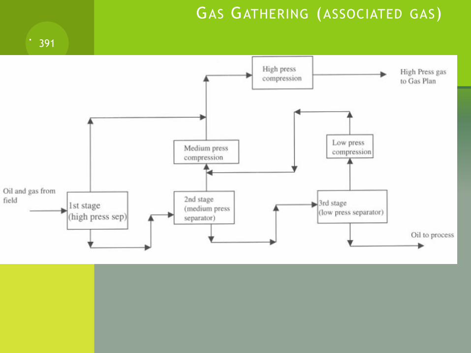
GAS GATHERING (ASSOCIATED GAS)
.391
GAS GATHERING (ASSOCIATED GAS)
If the gas plant is located at a far distance from the oil separating plant, booster compressors are required to maintain the correct plant inlet pressure.
Sometimes these booster compressors can be located at the gas plant or in the field midway between the oil/gas separating plant and the gas plant.
392
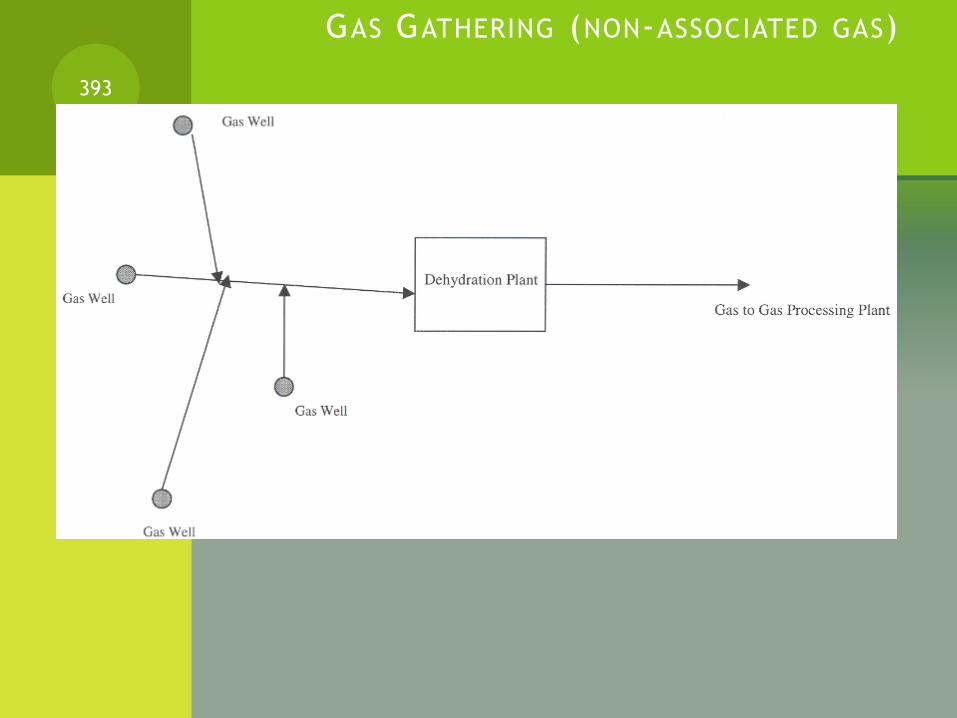
GAS GATHERING (NON-ASSOCIATED GAS)
393

GAS COMPRESSION
In the gas gathering compression system, knockout drums are required to remove the liquid which condenses from the gas during the compression process.
If knock out drums were not used to remove the liquid from the gas stream, damage to the gas compressors would occur.
Liquid in the gas stream has to also be removed before the gas enters the processes of the gas plant.
394
GAS COMPRESSION (CONTINUED)
Interstage and after cooling is required to remove the heat of compression during the compression process.
If the heat in not removed, the amount of power requires to compress the gas in a multistage compressor would be increased.
By cooling the gas, the temperature and the volume of the gas will be reduced. By reducing the temperature and volume of the gas, less power is required for multistage compression process.
By cooling the gas after compression, smaller pipe diameter can be used.
395
GAS COMPRESSION (CONTINUED)
Surge is the most important design consideration for centrifugal compressors.
The surge condition occurs when the compressor does not have enough flow to produce sufficient pressure-head. At this point, the gas in the discharge piping flows back into the compressor.
This lowers the back-pressure of the system, establishing forward flow at a temporary low head.
The forward-backward cycling through the compressor is called “surge” and is very detrimental to the compressor bearings and seal.
396
GAS COMPRESSION (CONTINUED)
Most compressors can only sustain a very few (100-200) cycles surge before severe mechanical problems develop.
Manufacturers of centrifugal compressors give surge limits of the compressor.
Control systems are used to maintain the compressor operation bellow the surge line.
397

GAS COMPRESSION (CONTINUED)
398

CHEMICALS USED FOR NATURAL GAS SWEETENING
Common chemicals that are used on gas sweetening are:
- Amines:
Monoethanolamine (MEA)
Diglycoamine (DGA)
Diisopropanolamine (DIPA)
Triethanolamine (TEA)
Methyldiethanolamine (MDEA)
- Benfield Process (hot carbonate)- The benfield process uses
low cost chemicals available.
399

SELECTION OF SWEETENING CHEMICALS
The following factors have to be considered when selecting gas sweetening chemicals:
Gas compression
Processing pressure and temperature
Quantity of sour gas to be removed
Product gas specification
Processing requirements of the acid gas
Processing requirements o the treated gas
Once the scope of the application has been decided, a specific process must be selected based upon the following factors:
Plant investment
Operating costs
400

AMINE GAS SWEETENING
ASSIGNMENT401

WORK
Wtotal = Wflow + Wshaft = d(PV) = P dV + V dP
Wflow: due to change in volume dV
Wshaft: due to the change in pressure dP
Three types of work (process)
1. isothermal process (at constant temperature): (e.g. pumping a liquid)
2. adiabatic process (no heat flow in or out of the system): (e.g. Gas Compression)
3. Polytropic process: (e.g. Gas Compression)
402
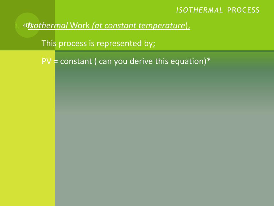
ISOTHERMAL PROCESS
1. Isothermal Work (at constant temperature),
This process is represented by;
PV = constant ( can you derive this equation)*
403
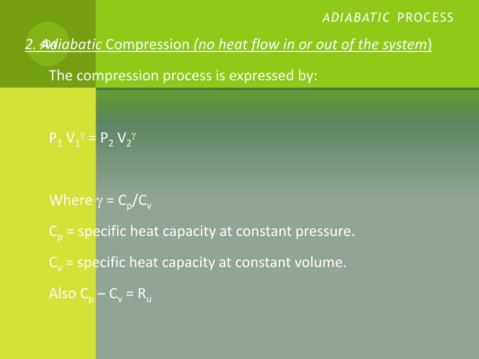
ADIABATIC PROCESS
2. Adiabatic Compression (no heat flow in or out of the system)
The compression process is expressed by:
P1 V1 = P2 V2
Where = Cp/Cv
Cp = specific heat capacity at constant pressure.
Cv = specific heat capacity at constant volume.
Also Cp – Cv = Ru
404
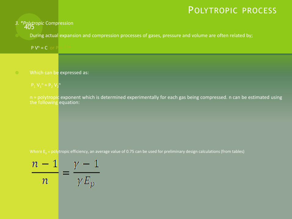
POLYTROPIC PROCESS
3. *Polytropic Compression
During actual expansion and compression processes of gases, pressure and volume are often related by;
P Vn = C or P = ??*
Which can be expressed as:
P1 V1n = P2 V2
n
n = polytropic exponent which is determined experimentally for each gas being compressed. n can be estimated using the following equation:
Where Ep = polytropic efficiency, an average value of 0.75 can be used for preliminary design calculations (from tables)
405

WORK
Work (W) for a closed system is given by :
Work (piston work) = Force x distance = F ds = P.A ds = P dV
Where:
P = pressure
A = cross sectional area of Piston
W = 12 P dV
Here we can substitute for P by the compression relationships, mentioned before (i.e. Isothermal, adiabatic, polytropic)
406
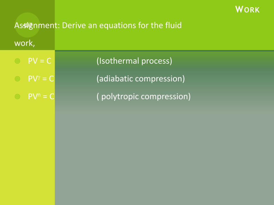
WORK
Assignment: Derive an equations for the fluid
work,
PV = C (Isothermal process)
PV = C (adiabatic compression)
PVn = C ( polytropic compression)
407

COMPRESSION POWER
Power = specific compression Work (fluid work) X Mass Flow rate*
Work for compression is determined from the energy equation, because it is an open system with flow of fluid through the compressor.
Neglecting the kinetic energy, potential energy and friction losses, the energy balance becomes:
dW = v dP
Integrating:
W = 12 v dP
where v = specific volume (can also be expressed as 1/ρ)
408
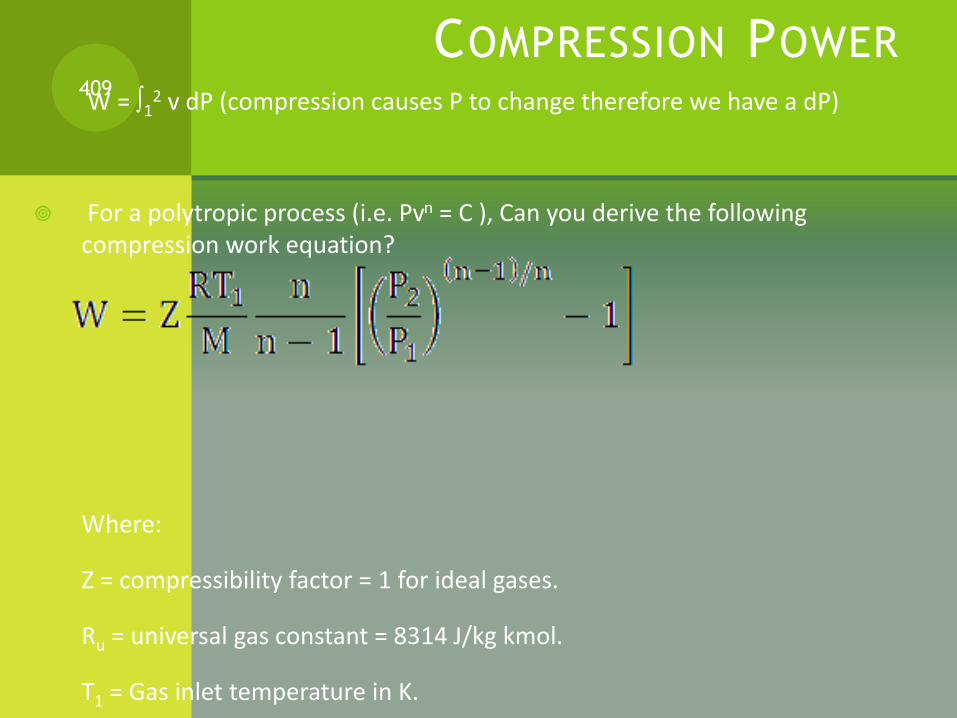
COMPRESSION POWER
W = 12 v dP (compression causes P to change therefore we have a dP)
For a polytropic process (i.e. Pvn = C ), Can you derive the following compression work equation?
Where:
Z = compressibility factor = 1 for ideal gases.
Ru = universal gas constant = 8314 J/kg kmol.
T1 = Gas inlet temperature in K.
409

More details:
410

REFRIGERATION LOOP
How does refrigeration work…… any ideas?
411
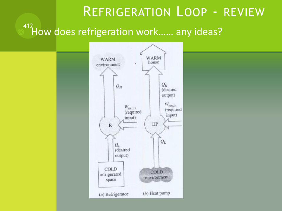
REFRIGERATION LOOP - REVIEW
How does refrigeration work…… any ideas?412

REFRIGERATION LOOP – REVIEW (CONTINUED)
Refrigeration Cycle (Reversed Carnot Cycle)413

REFRIGERATION LOOP – REVIEW (CONTINUED)
Gas Refrigeration Cycle: compare it with the Carnot refrigeration cycle as discussed in the previous slide.
414
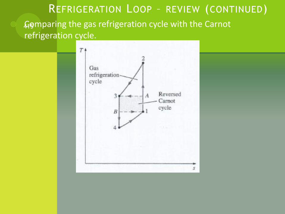
REFRIGERATION LOOP – REVIEW (CONTINUED)
Comparing the gas refrigeration cycle with the Carnot refrigeration cycle.415
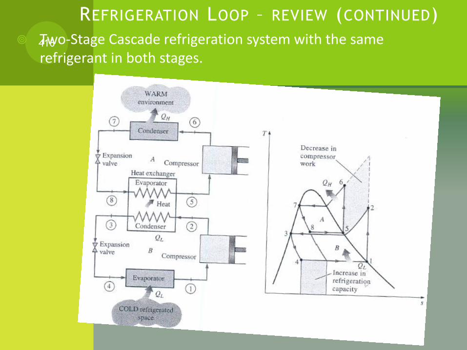
REFRIGERATION LOOP – REVIEW (CONTINUED)
Two-Stage Cascade refrigeration system with the same refrigerant in both stages.416

REFRIGERATION LOOP ( IN OIL/GAS PROCESSING)
A refrigeration system lowers the temperature of a fluid below that possible when using air or water at ambient conditions.
A typical building air conditioner cools air to a temperature of 1O-15°C. At the other end of the scale is the liquefaction of helium at - 268°C.
If the objective is to recover marketable liquids (NGLs) from a produced gas stream, basic economics controls the temperature specified
If it is to meet a hydrocarbon dewpoint, that specification and the processing pressure sets the required temperature
417
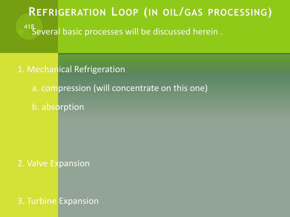
REFRIGERATION LOOP ( IN OIL/GAS PROCESSING)
Several basic processes will be discussed herein .
1. Mechanical Refrigeration
a. compression (will concentrate on this one)
b. absorption
2. Valve Expansion
3. Turbine Expansion
418
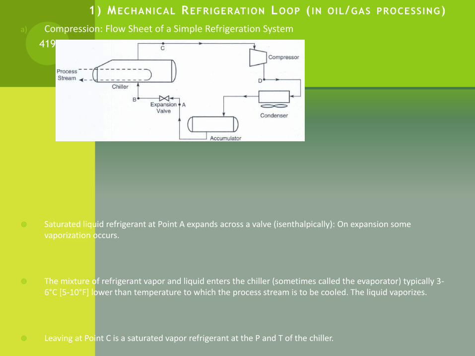
1) MECHANICAL REFRIGERATION LOOP ( IN OIL/GAS PROCESSING)
a) Compression: Flow Sheet of a Simple Refrigeration System
Saturated liquid refrigerant at Point A expands across a valve (isenthalpically): On expansion some vaporization occurs.
The mixture of refrigerant vapor and liquid enters the chiller (sometimes called the evaporator) typically 3-6°C [5-10°F] lower than temperature to which the process stream is to be cooled. The liquid vaporizes.
Leaving at Point C is a saturated vapor refrigerant at the P and T of the chiller.
419

REFRIGERATION LOOP ( IN OIL/GAS PROCESSING)a) Compression: Flow Sheet of a Simple Refrigeration System (FUGURE 1)
420
REFRIGERATION LOOP ( IN OIL/GAS PROCESSING)
Calculation involved:
I. Determination of refrigerant circulation rate.
II. Determination of Compressor Power
III. Determination of Condenser Heat Load (Qcond)
421

REFRIGERATION LOOP ( IN OIL/GAS PROCESSING)
I. Determination of refrigerant circulation rate.
Qchiller + mAhA = mchc where mA = mc = m
422
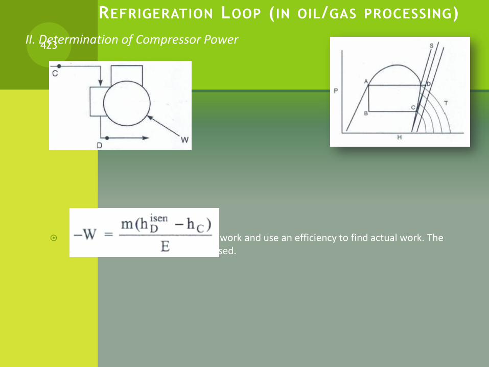
REFRIGERATION LOOP ( IN OIL/GAS PROCESSING)
II. Determination of Compressor Power
Calculate theoretical (isentropic) work and use an efficiency to find actual work. The circulation rate from Step (1) is used.
423

REFRIGERATION LOOP ( IN OIL/GAS PROCESSING)
III. Determination of Condenser Heat Load (Qcond)
Two ways to do this:
Knowing Qchiller and W, you can write the overall balance for (Simple Refrigeration System, FUGURE 1) to find Qcond (Note, W is negative, so Qcond is the sum of two negative numbers)
If you are performing the calculation manually and wish an independent
424

REFRIGERATION LOOP ( IN OIL/GAS PROCESSING)
Gas Refrigeration: Exercise
Given Hand out 1 “Refrigeration Systems”
Given Handout 2 “Pressure Enthalpy diagram”
Read hand out Pages 213 – 235
1) Sketch a refrigeration loop, showing the chiller, compressor, condenser, and accumulator. What's the role of each part (will discuss together on the board)
2) Relate the refrigeration loop to the thermodynamic diagram on page 217 of the handout and show the different steps of the refrigeration loop. (I will help you and we will do it on the board)
425
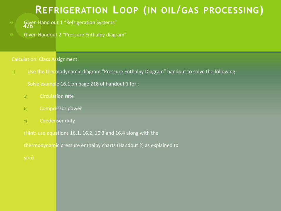
REFRIGERATION LOOP ( IN OIL/GAS PROCESSING) Given Hand out 1 “Refrigeration Systems”
Given Handout 2 “Pressure Enthalpy diagram”
Calculation: Class Assignment:
1) Use the thermodynamic diagram “Pressure Enthalpy Diagram” handout to solve the following:
Solve example 16.1 on page 218 of handout 1 for ;
a) Circulation rate
b) Compressor power
c) Condenser duty
(Hint: use equations 16.1, 16.2, 16.3 and 16.4 along with the
thermodynamic pressure enthalpy charts (Handout 2) as explained to
you)
426
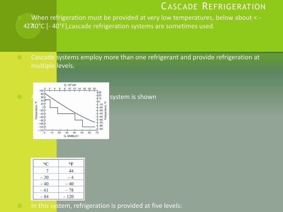
CASCADE REFRIGERATION
When refrigeration must be provided at very low temperatures, below about < -40°C [- 40°F],cascade refrigeration systems are sometimes used.
Cascade systems employ more than one refrigerant and provide refrigeration at multiple levels.
A propane/ethane cascade system is shown
In this system, refrigeration is provided at five levels:
427

CASCADE REFRIGERATION
The propane at - 40°C is used to condense the ethane refrigerant.
All of the heat picked up in the process is ultimately rejected to the cooling water at the propane condenser.
A hypothetical cooling curve for the process fluid has been developed to show the amounts and levels of refrigeration
428
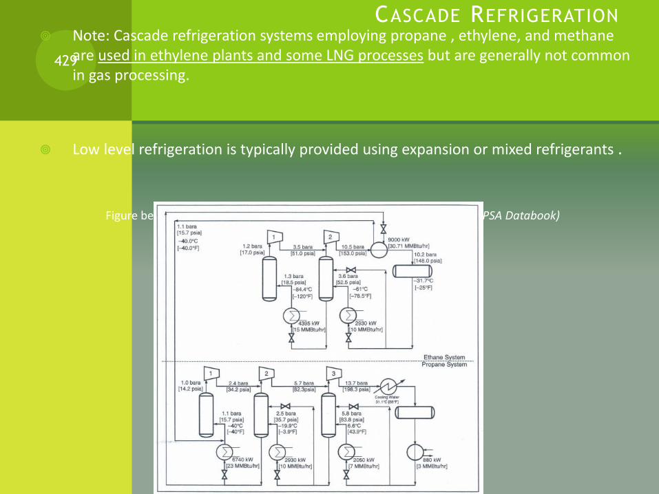
CASCADE REFRIGERATION Note: Cascade refrigeration systems employing propane , ethylene, and methane
are used in ethylene plants and some LNG processes but are generally not common in gas processing.
Low level refrigeration is typically provided using expansion or mixed refrigerants .
Figure below: Ethane-Propane Cascade Refrigeration System (Courtesy GPSA Databook)
429

EXPANSION REFRIGERATION
Recall: Two types of expansion refrigeration processes are
used in gas processing.
2. Valve expansion - often referred to as LTS, LTX or JT process
3. Turbine expansion - turboexpanders
430
2. VALVE EXPANSION
Valve expansion processes are common industrial processes (robust and relatively inexpensive)
On the hand it has a low thermodynamic efficiency and require high pressure feed gas [10 000 kPa (1500 psia) or higher] to be economically feasible.
The process is commonly used to process gases to meet hydrocarbon dewpoints.
431
2. VALVE EXPANSION (CONTINUED)Assignment/ Exercise: Expansion Valve (If time permits)
Given Handout (EXPANSION REFRIGERATION)
Read p231 – 235 and rework example 16.4 using the given
P-H diagram for methane.
432
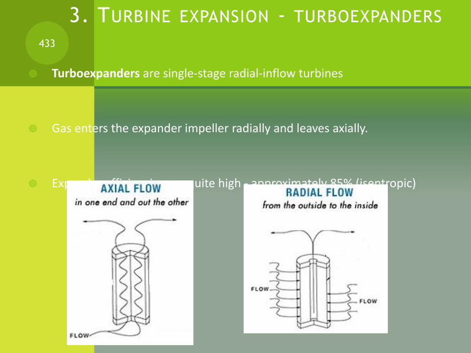
3. TURBINE EXPANSION - TURBOEXPANDERS
Turboexpanders are single-stage radial-inflow turbines
Gas enters the expander impeller radially and leaves axially.
Expander efficiencies are quite high - approximately 85% (isentropic)
433
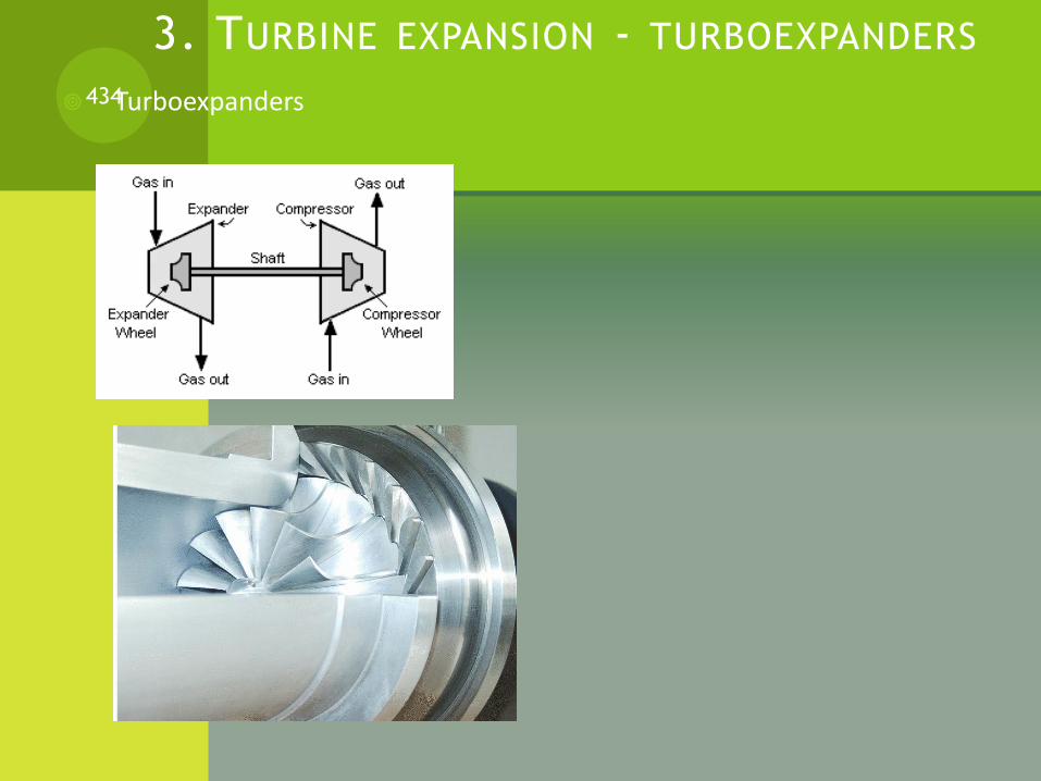
3. TURBINE EXPANSION - TURBOEXPANDERS
Turboexpanders434

3. TURBINE EXPANSION - TURBOEXPANDERS (CONTINUED)
Assignment/ Exercise: Turboexpanders
Given Handout (EXPANSION REFRIGERATION)
Read p235 – 238 and rework example 16.5 using the given
P-H diagram for methane and the data in example 16.4.
(i.e Calculate the temperature and work of the expander)
435
ESTIMATION OF EXPANDER EFFICIENCY
The best way to estimate efficiency is from actual performance data.
It is difficult to correlate efficiency data because many factors affect actual performance.
As with compressors, normal manufacturing tolerances can affect performance measurably.
Erosion can alter the shape of a wheel and thus efficiency.
The presence of liquids likewise may have a dramatic effect.
For all of these reasons, there may be a significant error in the estimated
436
ESTIMATION OF EXPANDER EFFICIENCY
Three factors can effect the expander efficiency (E) and therefore can be used to estimate (i.e. correlate) the expander efficiency
1. Specific speed of the impeller
2. Flow parameter
3. Specific turbine diameter
437
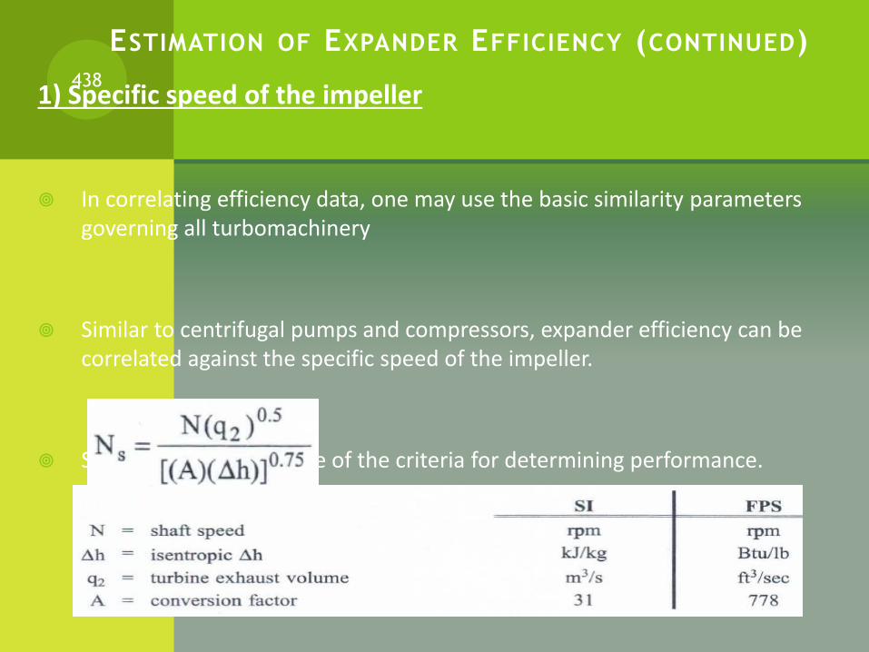
ESTIMATION OF EXPANDER EFFICIENCY (CONTINUED)
1) Specific speed of the impeller
In correlating efficiency data, one may use the basic similarity parameters governing all turbomachinery
Similar to centrifugal pumps and compressors, expander efficiency can be correlated against the specific speed of the impeller.
Specific speed (Ns) is one of the criteria for determining performance.
438

ESTIMATION OF EXPANDER EFFICIENCY (CONTINUED)
After calculating Ns, the following chart can be used to determine the efficiency.
The below chart is for expanders where the amount of liquid formed is minimal
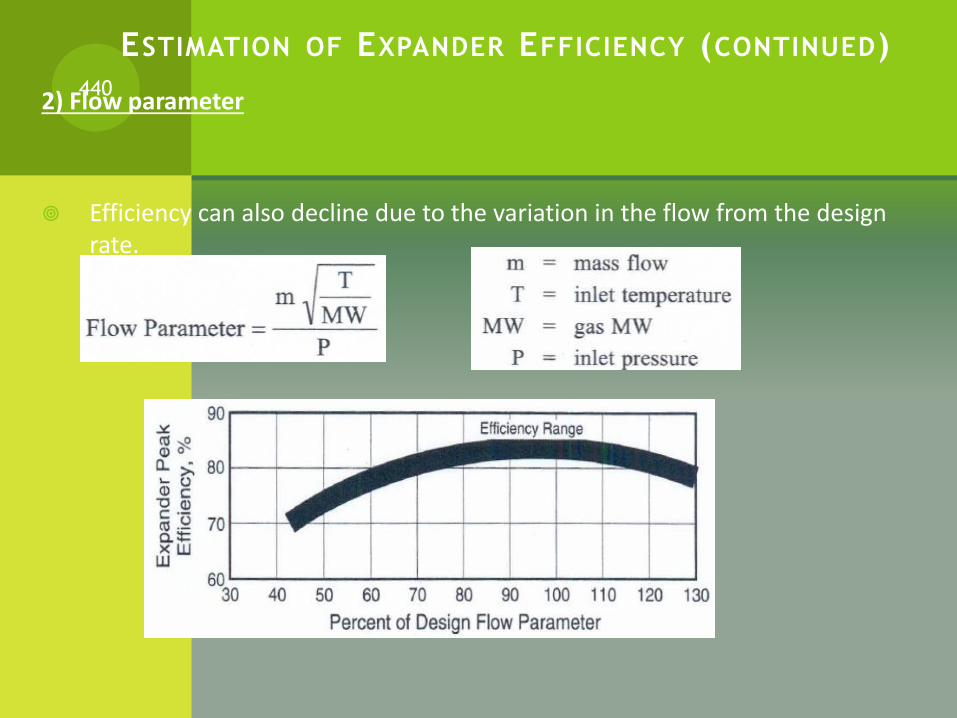
ESTIMATION OF EXPANDER EFFICIENCY (CONTINUED)
2) Flow parameter
Efficiency can also decline due to the variation in the flow from the design rate.
440

ESTIMATION OF EXPANDER EFFICIENCY (CONTINUED)
3) Specific turbine diameter
In addition to specific speed there are other parameters affecting expander performance such as specific turbine diameter.
441
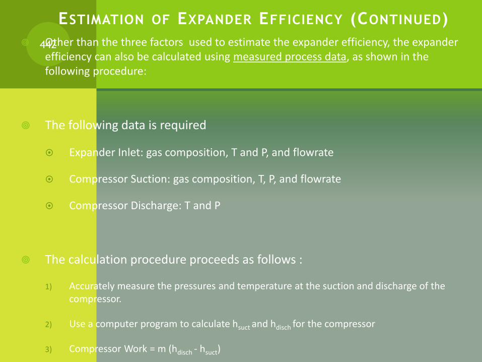
ESTIMATION OF EXPANDER EFFICIENCY (CONTINUED)
Other than the three factors used to estimate the expander efficiency, the expander efficiency can also be calculated using measured process data, as shown in the following procedure:
The following data is required
Expander Inlet: gas composition, T and P, and flowrate
Compressor Suction: gas composition, T, P, and flowrate
Compressor Discharge: T and P
The calculation procedure proceeds as follows :
1) Accurately measure the pressures and temperature at the suction and discharge of the compressor.
2) Use a computer program to calculate hsuct and hdisch for the compressor
3) Compressor Work = m (hdisch - hsuct)
442
MULTIPHASE FLOW
The use of multiphase flow systems is common practice in the oil and gas industry.
Multiphase flow is encountered in the well tubing, flow lines and gathering systems.
Furthermore, for transport of oil and gas to downstream processing facilities the preference, for economic reasons, is for a single pipeline in which both phases are transported simultaneously
Even in gas pipelines where the gas enters the line as a single phase fluid, condensation of liquids can occur due to pressure and temperature reduction along the line.
The calculation of pressure drop in a single phase line is relatively straightforward.
443
MULTIPHASE FLOW (CONTINUED)
In a multiphase line the gas and liquid can behave in a number of ways.
The liquid may run along the bottom of the pipe (stratified or wavy flow) it may be entrained as tiny droplets in the gas (mist flow) or it may form slugs (slug flow)
444
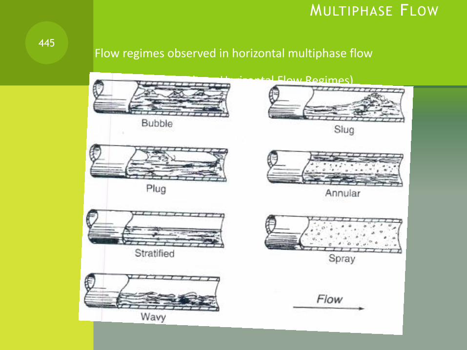
MULTIPHASE FLOW
Flow regimes observed in horizontal multiphase flow
(Various Two-Phase Horizontal Flow Regimes)
445

MULTIPHASE FLOW (CONTINUED) The character of flow depends on variables such as phase densities and
viscosities, the velocity of each phase, gas-liquid ratio and properties like surface tension.
The next figure shows 4 of the flow regimes that occur in vertical flow.
446
MULTIPHASE FLOW (CONTINUED)
In two-phase flow there are two phases, with different properties, interacting with the pipe wall as well as with each other.
A friction factor, therefore, depends on more, and complex, variables.
The difference between correlations depends to a large extent on how these variables are treated in order to fit the available data.
Each flow pattern (or regime) requires a different mathematical model to calculate pressure drop and liquid holdup*
447

MULTIPHASE FLOW (CONTINUED)
All models are based on the same thermodynamic principles and fluid flow principles
As with single-phase flow, a prediction of the "lost work" (friction drop) term is essentially empirical (experimental).
Thus, anyone method will be most reliable in the range of pipe sizes, fluid characteristics, flow conditions and geometry, and gas-liquid ratios used to develop the correlation.
448

MULTIPHASE FLOW (CONTINUED)
The primary concerns of the engineer working with multiphase systems are:
Pressure drop/line sizing
Liquid holdup*
Slugging and its effect on equipment sizing
Another diagram of slugging:
Figure: Slug flow of gas-liquid flow regime in horizontal pipe.
449
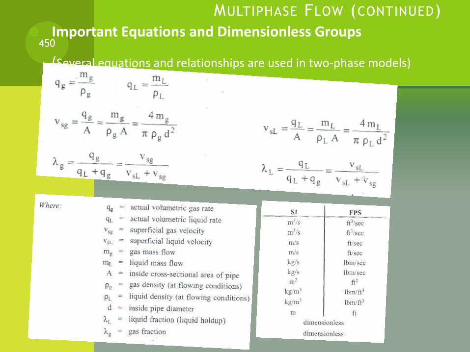
MULTIPHASE FLOW (CONTINUED)
Important Equations and Dimensionless Groups
(Several equations and relationships are used in two-phase models)
450
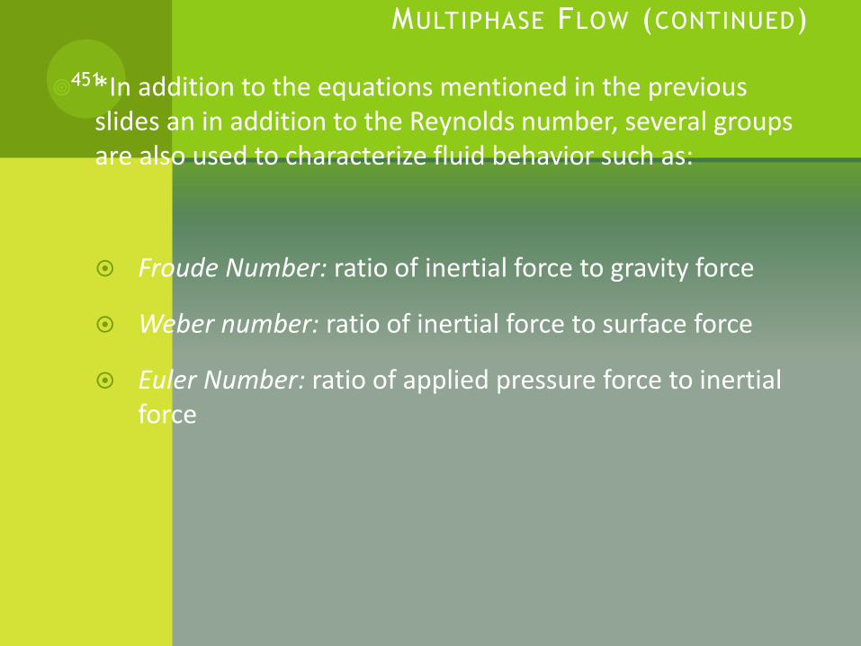
MULTIPHASE FLOW (CONTINUED)
*In addition to the equations mentioned in the previous slides an in addition to the Reynolds number, several groups are also used to characterize fluid behavior such as:
Froude Number: ratio of inertial force to gravity force
Weber number: ratio of inertial force to surface force
Euler Number: ratio of applied pressure force to inertial force
451
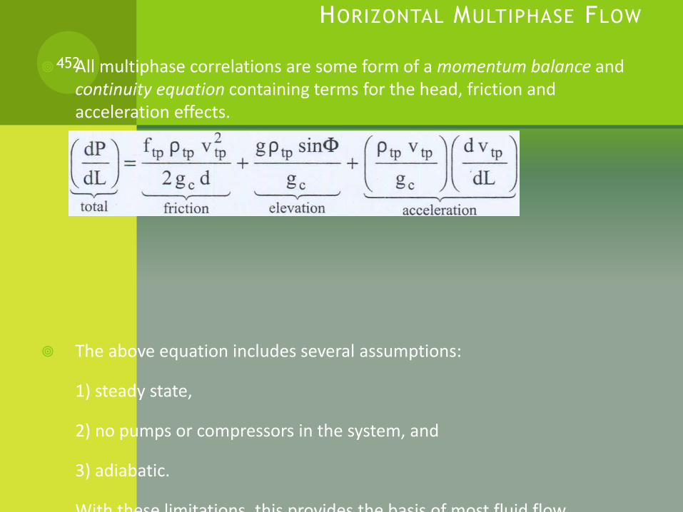
HORIZONTAL MULTIPHASE FLOW
All multiphase correlations are some form of a momentum balance and continuity equation containing terms for the head, friction and acceleration effects.
The above equation includes several assumptions:
1) steady state,
2) no pumps or compressors in the system, and
3) adiabatic.
With these limitations, this provides the basis of most fluid flow
452

FLOW REGIME MAPS
Flow regime can affect model selection in evaluating multiphase flow systems
The figure below is a simple flow regime map for two-phase flow in horizontal pipes.
453

FLOW REGIME EXAMPLE CALCULATION
Another figure below shows another widely used two phase flow regime map for horizontal or near-horizontal pipes.
454
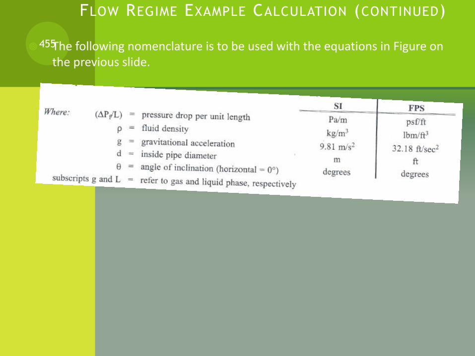
FLOW REGIME EXAMPLE CALCULATION (CONTINUED)
The following nomenclature is to be used with the equations in Figure on the previous slide.
455

FLOW REGIME EXAMPLE CALCULATION (CONTINUED)
Multi phase flow regime Assignment:
Using the chart in the previous page estimate
the flow regime of a horizontal gas pipe operating at 6900
kPa [1000 psia] and 15oC [59oC]. The gas density is 73
kg/m3 [4.6 lbm/ft3] and the liquid density is 700 kg/m3 [43.7
lbm/ft3], and the liquid viscosity is 0.5 cp. The gas rate is
5x10⁶ std m3/d [177 MMscf]. The gas MW is 18 and the gas
viscosity is 0.015cp. The inside pipe diameter is 0.432 m [17
in]. The condensate loading is 56 m3/106 std m3 [10
bbl/MMscf].
456

GLYCOL DEHYDRATION
Read Handout “Glycol Dehydration” and answer the question* in the given handout.
457


