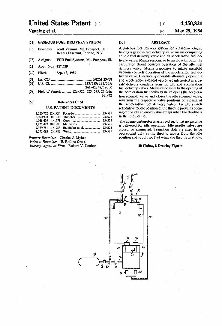
United States Patent [191 [111 4,450,821 Venning et al. [45] ,May 29, 1984 [54] GASEOUS FUEL DELIVERY SYSTEM [57] ABSTRACT [75] Inventors: Scott Venning, Mt. Prospect, 111.; A 33560115 fuel delivery _system for a gasoline ell_g_ille Dennis Discount, Jericho, NY‘ having a gaseous fuel delivery valve means ‘comprising _ an ldle fuel dellvery valve and an acceleration fuel de [73] Assignee: VCD Fuel Systems, Mt. Prospect, Ill~ livery valve. Means responsive to air flow through the _ ' carburetor throat controls operation of the idle fuel [21] Appl' No" 417’629 delivery valve. Means responsive to intake manifold [22] Filed; sep_ 13, 1982 vacuum controls operation of the acceleration fuel de livery valve. Electrically operable alternately open idle Int. (11.3 ........................................... .. and acceleration solenoid valves are interposed in sepa US. Cl. .................................. .. rate delivery conduits from the and acceleration _ 261/42; 48/180 R fuel delivery valves. Means responsive to the opening of [58] Fleld of Search -------- -- 123/527, 525, 575’ 27 GE; the acceleration fuel delivery valve opens the accelera 261/42 tion solenoid valve and closes the idle solenoid valve, [56] References Cited " reversing the respective valve positions on closing of US. PATENT DOCUMENTS 1,520,772 2,050,978 4,068,639 4,227,497 4,369,751 4,373,493 12/1924 8/1936 l/ 1978 10/1980 l/ 1983 2/ 1983 Ricardo ............. .. 123/525 Thatcher ...... 123/525 Cook . . . . . . . . . . . . . . . . . .. 123/525 Mathieson .......... .. 123/575 Batchelor et a1. .. 123/525 Welsh ................................ .. 123/525 Primary Examiner—Charles J. Myhre Assistant Examiner-E. Rollins Cross Attorney, Agent, or Firm-Robert V. Jambor the acceleration fuel delivery valve. An idle switch responsive to idle position of the throttle prevents open ing of the idle solenoid valve except when the throttle is in the idle position. i The engine carburetor is arranged such that no gasoline is delivered for idle operation. Idle needle valves are closed, or eliminated. Transition slots are sized to be operational only as the throttle moves from the idle position and supply no fuel when the throttle is at idle. 20 Claims, 8 Drawing Figures
Transcript
United States Patent [191 [111 4,450,821 Venning et al. [45] ,May 29, 1984
[54] GASEOUS FUEL DELIVERY SYSTEM [57] ABSTRACT
[75] Inventors: Scott Venning, Mt. Prospect, 111.; A 33560115 fuel delivery _system for a gasoline ell_g_ille Dennis Discount, Jericho, NY‘ having a gaseous fuel delivery valve means ‘comprising
_ an ldle fuel dellvery valve and an acceleration fuel de [73] Assignee: VCD Fuel Systems, Mt. Prospect, Ill~ livery valve. Means responsive to air flow through the
_ ' carburetor throat controls operation of the idle fuel [21] Appl' No" 417’629 delivery valve. Means responsive to intake manifold [22] Filed; sep_ 13, 1982 vacuum controls operation of the acceleration fuel de
livery valve. Electrically operable alternately open idle Int. (11.3 ........................................... .. and acceleration solenoid valves are interposed in sepa US. Cl. .................................. .. rate delivery conduits from the and acceleration
_ 261/42; 48/180 R fuel delivery valves. Means responsive to the opening of [58] Fleld of Search -------- -- 123/527, 525, 575’ 27 GE; the acceleration fuel delivery valve opens the accelera
261/42 tion solenoid valve and closes the idle solenoid valve, [56] References Cited " reversing the respective valve positions on closing of
Primary Examiner—Charles J. Myhre Assistant Examiner-E. Rollins Cross Attorney, Agent, or Firm-Robert V. Jambor
the acceleration fuel delivery valve. An idle switch responsive to idle position of the throttle prevents open ing of the idle solenoid valve except when the throttle is in the idle position. i
The engine carburetor is arranged such that no gasoline is delivered for idle operation. Idle needle valves are closed, or eliminated. Transition slots are sized to be operational only as the throttle moves from the idle position and supply no fuel when the throttle is at idle.
20 Claims, 8 Drawing Figures
U.S. Patent May 29, 1984 Sheet 2 of3 4,450,821
~56 / Ill
F83
90
US. Patent May 29, 1984 Sheet 3 of 3 4,450,821
Z0 /Z4 24 r20 w
4,450,821 1
GASEOUS FUEL DELIVERY SYSTEM
BACKGROUND OF THE INVENTION 1. Field of the Invention , ‘
The present invention relates to a gaseous fuel deliv ery system for gasoline engines. ‘More particularly it relates to a system which supplies gaseous fuel, such as propane, methane or natural gas to the gasoline engine during idle and acceleration conditions of operation. It is an improvement of the system described in U.S. Pat. No. 4,227,497. »
2. Description of the Prior Art - I The system disclosed in the aforesaid patent is in
tended to supply gaseous fuel to a gasoline engine dur ing portions of the operating cycle in which gaseous fuel operation is more efficient. These selected operat-' ing conditions are idle, acceleration, and increased load.
It was determined that the use of purely mechanical means to control idle gaseous fuel supply was trouble some and inaccurate. Also, dependency upon the rela tive magnitudes of engine vacuum resulted in wide ?uctuations in operating effectiveness. Unwanted oper ation of one or the other portion of the system to supply‘ gaseous fuel when not intended further diminished overall ef?ciency. Importantly,it also was determined that for idle operation, modi?cation of the carburetor of the gasoline engine equippedfor gaseous fuel supply 30 was necessary to maximize ef?ciency.
SUMMARY OF THE PRESENT INVENTION‘ The present invention is intended to'provide the ad-.
vantages of gaseous fuel operation in a‘gasoline engine without the disadvantages of the earlier design. The present invention incorporates means responsive to engine operating conditions vinto the'idle fuel-supply portion to the system. It also eliminates variable control of gaseous fuel supply during acceleration and provides positive, electrically operated cutoff of the gaseous fuel supply during periods when such supply is unneeded. This arrangement eliminates the ability to automatically respond to variable load, but significantly improves idle and acceleration performance. .. I 1
The system of the present invention is applicable to new as well as existing engines. _It could be supplied as original equipment or added as a conversion at some later time. ' - . ' > '
In the preferred form, the system includes supply valve means responsive to absence of flow of‘ air through the carburetor venturi to permit supply of a preselected quantity of gaseous fuel during idle opera tion of the engine and responsive to loss of intake mani fold vacuum to permit supply of a preselected supple mental quantity of gaseous fuel during engine accelera tion. It further includes positive electrically operated valve means responsive to engine throttle position and manifold vacuum to insure delivery of idle or_accelera tion gaseous fuel supply only at the proper portions of the operating cycle. , , _ - , A
The carburetor used with the system is arranged such that no gasoline fuel is delivered to the engine at idle, yet as operation is elevated above idle, a small supply of gasoline commences prior to termination. of the idle gaseous fuel supply. I
15
25
35
45
50
2 l
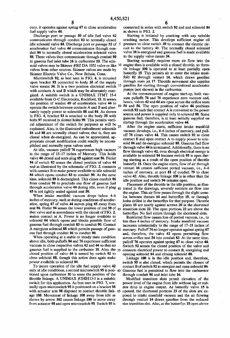
DESCRIPTION OF: THE ERAWINGS FIG. 1 is apartially sectional view of the system of
the present invention. ~ - I 1
FIG. 2 is an electrical schematic components of the system. ‘ ‘ 7
FIG. 3 is a plan view, partially in‘section, of the sup ply valve means of the present invention. " ‘ FIG. 4 is aside view of the supply valve means of
FIG. v3. ‘ '
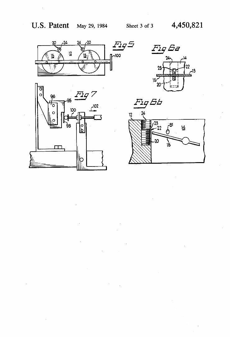
FIG. 5 is a top view of the base plate of the carbure tor incorporating the system of _ the presentinvention. FIGS. 6a and 6b are fragmentary views of portions of
the base plate of the carburetor of FIG. 5. =
of the electrical
FIG. 7 is a fragmentary side elevational‘ view of a‘ portion of the carburetor of FIG. 5.‘ '
DETAILED DESCRIPTION ‘The'system of the ‘present invention is applied in
conjunction with the carburetor of an'internal combus tion engine utilizing gasoline fuel. It is interconnected,‘ for example, with a dual barrel carburetor 10 illustrated in the drawings, which includes a‘r'emovablev base plate 12, central throats 14 and pivotal butterfly valve plates 15 pivotally mounted in base plate 12 and controlled by the engine throttle linkage. Of course, a carburetor having additional or ‘fewer barrels“(venturis)) could be utilized. Any suitable gasoline carburetor may be used, such as the products of Rochester Carburetor Com-V pany, a Division of General Motors Corporation. Spe cities, of carburetor functions 'to_ supplyvgasoline to an engine are illustrated and described in numerous refer ence works, such as, for example, ”Rochester Carbure tor”, a publication of H. P. Books, P. O. Box ‘5367, Tucson, ‘Ariz. 85708,,printed 1973, Library of Congress Catalog Card Number 72-91 685.'Reference is made to that publication for an understanding of the typical: gasoline carburetor with which the present ‘invention is . intended to cooperate. ~ _ . = .
Illustrated carburetor 10_ is not whollyeonventional. It is modi?ed, or in the instance of original equipment, . constructed differently froma ‘carburetor for supplying only gasoline toan internal combustion engine. Carbu retor 10 includes gaseous fuel inletrtllbe .16 through which the gaseousfuel is supplied in accordance with ‘the present invention. This maycbe located above or below butterflys 15. I r , _ . _ I F .
In accordance with the present invention, it is neces sary to eliminate all supply of gasoline fuelat idle‘; Usu allyv twosources exist, the mainidle circuit, which in cludes adjustable idle fuel jets and in most carburetors transition slots, which are formed in the throat of carbu-. retor adjacent the closed position of thebutter?y
5 valves. .
60
65
Idle needle valves are closed so that no fuel is .deliy ered to the idle circuit of the carburetor. The idle circuit is normallya passage separate from the. throat and supplies gasoline and air even though the butter?y valves are closed or. nearly closed. Fuel, metered through the idle needle valves, is the major idle fuel supply. In the present system all gasoline Ql‘illqllld fuel supply is eliminated at idle. As illustrated in FIGS. .5 through 7, thecarb'uretor’o
the present invention includes transitionifislots .22,‘ formed in throats 14 of carburetor 10,1which permit quantities of gasoline to enter the carburetor-throat 14. They generally operate to supplement idle fuelsupply
4,450,821 3
until the main carburetor jets 17 commence fuel deliv ery. '
‘As seen in FIGS. 5, 6a and 6b, the base plate 12 of carburetor 10 has been modi?ed to signi?cantly shorten the “transition slots” 22 which exist in the walls forming the throats 14, such that they are‘closed at idle and not exposed to the high intake manifold vacuum between the closed butter?ys. Thus, no gasoline can be drawn into the carburetor throat. In modifying an existing carburetor 10 the slots 22 are conveniently restricted by inserting set screws 20 from the top of carburetor base plate 12. Appropriate threaded holes 24 are formed in base plate 12 to accommodate threaded set screws 20.
It is important to note that the screws are positioned such that the transition slots are blocked when the but ter?y plate is in the closed or idle position. That posi tion of plate 15 at idle is as shown at 13 in FIG. 60. At idle no gasoline can be drawn into the carburetor through the shortened portions 23 of slots 22, because they are above the closed portion of the butter?y. As the butter?ys 15 are moved from the idle position, some amount of gasoline is drawn into the throats 15 through the shortened slots 23. This is intended to avoid any possible lag in operation as transition is made from idle to operational modes. It occurs, because as the butter ?ys 15 are pivoted toward the open or vertical position, the shortened slots 23 are exposed to the intake mani fold vacuum. The power valves of the carburetor 10 are also elimi
nated. This is done by removing, or in the case of origi nal equipment, excluding the typical power valves found in a carburetor which enrichens the fuel mixture under load. This substantially reduces the amount of liquid fuel which will enter the carburetor on accelera tion. The fuel delivery system illustrated in the embodi
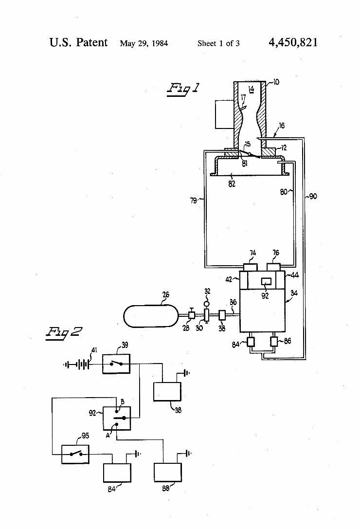
ment in FIGS. 1 through 8, includes a pressure vessel 26 for storage of a gaseous fuel supply, a shut-off valve 28, adjustable pressure regulator 30 with gauge 32, supply valve means 34, and connecting delivery conduits 36. The fuel utilized may be propane, methane, natural gas or similar suitable gaseous fuel. The vessel 26 may be placed in any suitable location, for example, in automo tive applications it may be placed in the trunk, or be tween the frame rails.
Regulator 30 and gauge 32 are utilized to set an ap propriate supply pressure for delivery of gaseous fuel to the supply valve means 34 at essentially constant pres ent pressure. As can be appreciated, the pressure level will vary with the size of the engine with which the system is associated. Typically, a system for an engine of 200 cubic inch displacement will operate satisfacto~ rily at 1.5 to 2.0 psig. (pounds per square inch, gauge) supply pressure.
Fuel supply line 36 provides a connection between regulator 30 and supply valve means 34. Interposed in line 36 is a normally closed solenoid valve 38 connected to the electrical power supply of the engine, which in this embodiment ‘includes battery 41. Solenoid 38 is operated by oil pressure switch 39 which closes the electrical circuit and permits solenoid 38 to open only when the engine is cranking and has developed oil pres sure.
As best‘ seen in FIG. 3, supply valve means 34 in cludes a‘ housing or body 35 forming two separate valves, idle fuel valve 42 and acceleration fuel valve 44. Supply line 36 delivers gaseous fuel through two sepa rate, inlet passages .46 and 48. These passages respec
0
20
25
30
35
50
55
60
65
4 tively connect to two separate discharge passages 50 and 52 across ori?ce de?ning valve seats 54 and 56. Each of the valves 42 and 44 includes rod 58 slidably
supported in bores formed in body 35. Tapered lower portions of the rods form valve plugs 64 and'65 which coact with valve seats 54, 56 to open and close commu nication between passages 46 and 50 and passages 48 and 52. The plugs are tapered to provide adjustability of effective ori?ce size of the annular opening between plug and seat when the valves are in the open position. The maximum diameter of the tapered portions exceeds the ori?ce size of the seats 54, 56 so that when the valves are in the closed position the ori?ces are'com pletely closed. . Upper ends of rods 58 are threaded into adjustment
nuts 66 which are adjustable to vary the length of the rod, nut combination, and consequently the effective ori?ce size of the annulus between seats 54, 56 and plugs 64, 65. It has been determined that the effective ori?ce _ size (equivalent circular ori?ce) for the valve 42 is in the range of 0.040 to 0.070 inches diameter and the effective ori?ce size for the valve 44 is in the range of 0.060 to 0.080 inches diameter. Springs 67 operate against wash ers 69 and urge valve rods 58 toward the open position. Each of the rods 58 is connected to a vacuum pulloff
74, 76, through connectors 58. These vacuum motors operate, as will be explained, to seat the tapered plugs 64, 65 against seats 54, 56 under appropriate operating conditions. These devices are well known and commer cially available from F&B Mfg. Co., Catalogue No. 30-3. F&B Mfg. Co. is located at 4248 West Chicago Avenue, Chicago, Ill. Vacuum pulloff 74 is connected via conduit 79 to the
port 81 in venturi or throat of caburetor 10. Port 81 is located as would be a vacuum advance port in the throat of a carburetor. It is positioned upstream of the butter?ys 15 such that when the throttle is closed and butter?ys 15 are positioned as shown in FIGS. 1 and 6, the butter?ys are between the port 81 and the intake manifold. When the butter?ys are moved to an open position, port 81 is exposed to intake manifold vacuum and the ?ow of air through the throat 14.
Conduit 79 senses ported vacuum, that is, vacuum created as a result of ?ow of air through the venturi ?owing over port 81 and operates to pull rod 58 of idle fuel valve 42 closed when there is sufficient air ?ow through the carburetor throat. This occurs when the engine is operating other than at idle conditions. At idle, the ported vacuum ori?ce 81 is blocked or disposed above the butter?y and it does not experience the intake manifold vacuum below the butter?ys 15. Hence, there is no ?ow across it and no ported vacuum. Spring 67 urges valve 42 open. Vacuum pulloff 74 is sized such that open experiencing a ported vacuum in excess of about 4-6 inches of mercury, it will operate against spring 67 and close idle valve 42.
It should be understood that vacuum is a negative valve. That is, a vacuum near zero, measured in inches of mercury, is a smaller or lesser vacuum than a vacuum of 4 or 10 inches of mercury. Vacuum pulloff 76 is connected via conduit 80 to the
intake manifold 82 of the engine incorporating thesup plemental fuel delivery system. It senses, and responds to, manifold vacuum to pull the valve rod 58 of acceler ation fuel valve 44 closed when manifold vacuum exits, such as during idle and cruise operation. Vacuum pull off 76 is sized such that upon experiencing an intake manifold vacuum in excess of about 4-6 inches of mer
4,450,821 5
cury, it operates against spring 67 to close acceleration fuel supply valve 44.
Discharge port or passage 50 of idle fuel valve 42 communicates through conduit 83 to normally closed idle solenoid valve 84. Discharge port or passage 52 of acceleration fuel valve 44 communicates through con duit 86 to normally closed acceleration solenoid valve 88. These valves then communicate through conduit 90 to gaseous fuel inlet tube 16 in carburetor 10. The sole noid valves may be Skinner #BZ DA 1052 valve or like valves from other sources. Skinner valves are made by Skinner Electric Valve Co., New Britain, Conn. Microswitch 92, as best seen in FIG. 4, is mounted
upon bracket 93 connected to body 35 of the supply valve means 34. It is a two position electrical switch with contacts A and B which may be alternately ener gized. A suitable switch is a UNIMAX 3TMT 15-4 available from G-C Electronics, Rockford, Ill. It senses the position of washer 69 of acceleration valve 44 to operate the switch between contacts A and B and alter nately supply power to solenoids 88 and 84. As shown in FIG. 4, bracket 93 is attached to the body 35 with bolts 97 received in slotted holes 99. This permits verti cal adjustment of the switch for purposes as will be explained. Also, in the illustrated embodiment solenoids 84 and 88 are normally closed valves; that is, they are closed when de-energized. As can be appreciated, ap propriate circuit modi?cation could readily be accom plished and normally open valves used.
5
6 connected in series with switch 92 and and solenoid 84 as shown in FIG. 2.
Starting is initiated by cranking with any suitable cranking motor. This develops suf?cient engine oil pressure to close switch 39 to connect the electric cir cuit to the battery 41. The normally closed solenoid valve 38 is energized and gaseous fuel is made available
1 to the supply valve means 34.
At idle, vacuum pulloff 76 experiences high vacuum “ in the range of 15-17 inches of Mercury. This holds valve 44 closed and seats plug 65 against seat 56. Feeler 94 of switch 92 senses the closed position of valve 44 and as illustrated by the schematic of FIG. 2, connects with contact B to make power available to idle solenoid 84 which opens conduit 83 to conduit 90. At the same time, solenoid 88 is deenergized. This closes conduit 86 from conduit 90 to preclude any flow of gaseous fuel through acceleration valve 44 during idle, even if plug 65 is not tightly sealed against seat 56. When intake manifold vacuum drops below 4-6
inches of mercury, such as during conditions of acceler ation, spring 67 of valve 44 moves plug 65 away from seat 56. Feeler 94 senses the lower position of rod 58 of that valve and in accordance with the circuit of FIG. 2, makes contact at A. Power is no longer available to solenoid 84 which opens and blocks possible ?ow of gaseous fuel through conduit 83 to conduit 90. Contact A energizes solenoid 88 which permits passage of gase ous fuel through conduit 86 to conduit 90. When operating at a stable or steady state condition
above idle, both pulloffs 84 and 76 experience suf?cient vacuum to close respective valves 42 and 44 so that no gaseous fuel is supplied to the carbuetor 10. Also, the closed position of valve 44 is sensed by switch 92 to close sole'noid 88, though this action does again make power available to solenoid 84. To insure operation of the idle fuel supply valve 42
only at idle conditions, a second microswitch 95 is posi tioned upon carburetor 10 to sense the position of the throttle linkage. A UNIMAX #ZHBI 13-1 is a suitable switch for this application. As best seen in FIG. 7, nor mally open microswitch 95 is positioned on a bracket 96 with actuator arm 98 disposed to contact throttle link age 100. Movement of linkage 100 away from idle as shown by arrow 102 causes linkage 100 to move away from actuator 98 and open microswitch 95. Switch 95 is
40
45
50
65
Starting normally requires more air ?ow into the engine than is available with a closed throttle, so throt tle linkage 100 is operated to at least partially open butter?y 15. This permits air to enter the intake mani fold 82 through venturi 14, which draws gasoline through main jet l7. Throttle movement also supplies gasoline for starting through conventional. accelerator pumps (not shown) in the carburetor. At the commencement of engine start-up, both vac
uum pulloffs 74 and 76 experience zero vacuum and, hence, valves 42 and 44 are open across the ori?ce seats 54 and 56. The open position of valve 44 positions switch 92 such that contact A is converted to the power source and power is supplied only to solenoid 88. Some gaseous fuel, therefore, is at least initially supplied on startup through the acceleration valve 44.
After the engine starts, suf?cient intake manifold vacuum develops, i.e., 4-6 inches of mercury, and pull off 76 closes valve 44. This causes switch 92 to close contact B and open contact A to supply power to sole noid 84 and de-energize solenoid 88. Gaseous fuel flow through valve 44 is terminated. Additionally, there is no ?ow through valve 42, even though electrical energy is available to solenoid 84 because switch 95 is open dur ing starting as a result of the open position of throttle butter?y 15. Once the engine starts, ?ow of air through venturi 14 creates suf?cient ported vacuum, i.e., 4~6 inches of mercury, at port 81 of conduit 79 to close valve 42. Also, throttle linkage 100 is in other than the idle position and switch 94 remains open. Placement of the throttle in the idle position, as illus
trated in the drawings, severely restricts air ?ow into the engine. This air ?ow passes through the slight annu lus between throats 14 and butter?ys 15, or through holes drilled in the butter?ys for that purpose. Throttle plates 15 are nearly against screws 20 in the shortened transition slots 22. The open portions 23 are above the butter?ys. No fuel enters through the shortened slots.
Restricted ?ow causes loss of ported vacuum, i.e., to less than 4 inches of mercury. Intake manifold vacuum increases substantially to the range of 17-18 inches of mercury. Pulloff 74 no longer operates against spring‘ 67 and, therefore, the valve 42 opens permitting ?ow across ori?ce seat 54 into conduit 83. At the same time, pulloff 76 operates against spring 67 to close valve 44. Switch 92 senses the closed position of the valve and connects electrical power to contact B, energizing and opening solenoid 84 and closing solenoid 88.
Linkage 100 is in the idle position and, therefore, switch 95 is also closed, which permits the closure of contact B of switch 92 to energize and open solenoid 84. Gaseous fuel is permitted to ?ow'into the carburetor through conduit 90 and inlet tube 16. Modi?ed transition slots permit elevation of the
power level of the engine from idle without lag or sud den drop in engine output. As butter?y valve 15 is opened, the shortened portions 23 of the slots are ex posed to intake manifold vacuum and the air flowing through venturi 14 draws, gasoline from the reduced size transition slot. Also, as the butter?ys 15 open above
4,450,821 7
the port 81, it is exposed to intake manifold vacuum. Also, air flow past butter?ys 15 increases. These factors increase ported vacuum and commence closure of gase ous idle fuel valve 42. As throttle linkage is moved from idle, switch 95 opens and de-energizes solenoid 84, fur ther insuring termination of gaseous fuel supply through conduit 83. Transition slots 23, however, permit gaso line flow as soon as butterflys 15 are moved above the set screws 20. This opens slots 23 to intake manifold vacuum and allows liquid fuel to be delivered simulta neously with, or immediately prior to termination of idle gaseous fuel supply. Under normal load, butterflys 15 are open to a posi
tion dependent on load requirements. Air ?ow through venturi 14 creates suf?cient ported vacuum, i.e., over 4-6 psig. inches of mercury, to cause pulloff 74 to hold valve 42 closed. There is also suf?cient intake manifold vacuum, i.e., in excess of 4-6 inches of mercury, to cause pulloff 76 to hold valve 44 closed. Electrically, switch 92 closes contact B, thus de-energizing solenoid 88 and making power available to solenoid 84. Throttle linkage 100, however, is out of the idle position. Hence, switch 95 is open and solenoid 84 remains deenergized. Under these conditions, fuel is supplied solely in liquid form through carburetor 10. On acceleration, throttle 100 is operated to further
open butterfly 15. This results in a loss of intake mani fold vacuum. As that parameter reduces to 4-6 inches of mercury or less, vacuum pulloff 74 no longer is capable of holding valve 44 closed against the action of spring 67. As valve 44 opens, switch 92 operates to contact A and energize solenoid 88. Solenoid 84 is disconnected from the source of power and is therefore closed. Opening of valve 44 permits gaseous fuel to pass
between ori?ce valve seat 56 and plug 65 into passage or conduit 86. Since solenoid 88 is open, gaseous fuel is permitted to flow into conduit 90 and delivery tube 16 to supplement gasoline drawn into carburetor 10 through jet 17. Use of gaseous fuel to supplement gaso line under acceleration is advantageous because gaseous fuel is of a higher octane and enrichens the total fuel mixture using less fuel than if operated on liquid fuel alone. Once steady state load conditions are reached, throt
tle butterflys 15 are moved toward a more closed posi tion and intake manifold vacuum again exceeds 4-6 inches of mercury. This closes valve 44 to shut-off ac celeration gaseous fuel supply. Also, this movement operates switch 92 to contact B, de-energizing solenoid 88. Since throttle linkage 100 is not in the idle position, switch 95 causes solenoid 84 to remain de-energized and no gaseous fuel is supplied to the engine until a condi tion of idle or acceleration is re-established.
It has been determined that under certain conditions of light acceleration intake manifold vacuum does not fall below the minimum at which spring 67 of valve 44 can fully override pulloff 76. At the same time, ported vacuum may also drop with the possibility that valve 42 may move slightly open. Microswitch 92 is mounted on body 35 by bracket 93
such that it may be adjusted vertically. In this way it may be adjusted to respond to different positions of washer 69 dependent upon operating characteristics desired. Positioning of switch 92 vertically with respect to valve 44 dictates when switch 92 will close contact A, and, hence, energize solenoid 88 and de-energize solenoid 84. This switch may be positioned to respond to slight movement of rod 58, or may be moved verti
5
10
15
20
25
30
35
45
55
65
8 cally lower to respond only when the valve rod has nearly reached the end of its opening travel. If posi tioned in its vertically upward maximum location, it will respond to movement of valve stem 58 of valve 44 as soon as intake manifold vacuum begins to reduce below 4-6 inches of mercury, which represents the commencement of opening of plug 65 from seat 56. If positioned at the vertically lowermost position, it will not sense movement of valve rod 58 by spring 67 until the annulus between plug 65 and seat 56 is fully open. This would, for example, require reduction of intake manifold vacuum to 2-3 inches of mercury. In this way, opening of solenoid 88 can be controlled to occur at a predetermined desired condition of acceleration.
Various features of the present invention have, hence, been disclosed in connection with the illustrated cm bodiments of the present invention. However, numer ous modi?cations may be made without departing from the spirit and scope of the invention as de?ned by the appended claims. We claim: 1. A gaseous fuel delivery system as for an internal
combustion engine normally operable on liquid fuel, the combination comprising:
a. idle delivery means responsive to engine operating conditions to supply gaseous fuel to said engine when said engine is operating at idle; acceleration delivery means responsive to engine operating conditions to supply gaseous fuel to said engine when said engine is accelerating;
. conduit means communicating said idle and accel ' eration delivery means to a source of gaseous fuel and to said engine
wherein said system includes: a. means responsive to ported vacuum created by ?ow of air into said engine to open and close said idle delivery means; said means opening said idle delivery means when said engine is at idle and closing said idle delivery means when said engine is operating at other than idle;
b. means responsive to the vacuum in the intake mani fold of said engine to open and close said accelera tion delivery means.
2. A gaseous fuel delivery system for an internal com bustion engine as claimed in claim 1 wherein said system includes: means closing communication from said idle delivery means to said conduit to the engine when said ac celeration delivery means is open, and opening communication from said acceleration delivery means to said conduit to the engine said means further opening communication from said idle de livery means to said conduit to the engine when said acceleration delivery means is open and clos ing communication from said acceleration delivery means to said conduit to the engine.
3. A gaseous fuel delivery system as claimed in claim 1 wherein said idle delivery means includes an idle fuel delivery valve and said acceleration delivery means includes an acceleration fuel delivery valve.
4. A gaseous fuel delivery system as claimed in claim 3 wherein said system includes:
a vacuum pulloff connected to said idle fuel delivery valve responsive to ported vacuum created by flow of air into said engine to open and close said idle delivery means and a vacuum pulloff connected to said acceleration fuel delivery valve responsive to
4,450,821 9
intake manifold vacuum of said engine to open and close said acceleration delivery valve. ' “
5. A gaseous fuel delivery system as claimed in claim 4 wherein said system includes: ‘_ . v
a. an idle solenoid valve intermediate ery valve and said engine;
b. an acceleration solenoid valve intermediate said acceleration delivery valve and said engine; and
c. means responsive to the opening and closing of said acceleration delivery valve to open said accelera tion solenoid valve and close said idle solenoid valve when said acceleration delivery valve is open and to close said acceleration solenoid and open said idle solenoid when said acceleration delivery valve is closed.
6. A gaseous fuel delivery system as claimed in claim 5 wherein said system further includes means respon sive to the position of the throttle of said engine to permit opening of said idle solenoid valve only when said engine throttle is at the idle position.
7. A gaseous fuel delivery system as claimed in claim 6 wherein said means responsive to the opening and closing of said acceleration delivery valve and said means responsive to the idle position of said throttle of the engine are electrical switches connected to said solenoid valves and adapted to connect to a source of electrical power.
8. A gaseous fuel delivery system for an internal com bustion engine as claimed in claim 4 wherein said vac uum pulloff connected to said idle fuel delivery valve opens said valve when the ported vacuum is about 4 to 6 inches of mercury or less.
9. A gaseous fuel delivery system for an internal com bustion engine as claimed in claim 4 wherein said vac uum pulloff connected to said acceleration fuel delivery valve opens said valve when said engine intake mani fold vacuum is about 4 to 6 inches of mercury or less.
10. A gaseous fuel delivery system as claimed in claim 9 wherein said vacuum pulloff connected idle fuel deliv ery valve opens said valve when the ported vacuum is about 4 to 6 inches of mercury or less, and said vacuum pulloff connected to said acceleration fuel delivery valve opens said valve when said engine intake mani fold vacuum is about 4 to 6 inches of mercury or less.
11. A gaseous fuel delivery system for an internal combustion engine, operable on liquid fuel, comprising:
a. a supply of gaseous fuel under pressure; b. a gaseous fuel delivery valve means having:
(1) an idle fuel delivery valve; (2) an acceleration fuel delivery valve;
0. means responsive to engine operation to control opening and closing of said fuel delivery valve means including: (1) means responsive to ported vacuum to open and
close idle fuel delivery valve; (2) means responsive to intake manifold vacuum to open and close acceleration fuel delivery valve;
d. Conduit means communicating said gaseous fuel from said supply to said delivery valve means and from each said idle fuel delivery valve and acceler ation fuel delivery valve to said engine;
e. electrically operable solenoid valve means ar ranged for alternate opening and closing compris mg: (l) idle solenoid valve means adapted to open and
close said conduit means from said idle fuel de livery valve to said engine;
said idle deliv
15
20
25
30
35
45
so
55
60
65
10 (2) acceleration solenoid valve means adapted to open and close said conduit means from said idle
7 fuel delivery ‘valve; , ., ,
said means responsive to engine operation further in cluding switch means to alternately open one said sole noid valve means and close the other thereof in re sponse to opening and closing of said acceleration fuel delivery valve, said switch means opening said acceler ation solenoid valve when said acceleration fuel deliv ery valve is open, closing said idle solenoid valve and, opening said idle solenoid valve when said acceleration fuel delivery valve is closed, said closing acceleration solenoid valve.
12. A gaseous fuel delivery system for an internal combustion engine as claimed in claim 11 including solenoid valve means, interposed in said conduit from said supply to said delivery valve means and switch means responsive to oil pressure in said engine to oper ate said solenoid valve means to permit gaseous fuel ?ow only when oil pressure exists in said engine.
13. A gaseous fuel delivery system for an internal combustion engine as claimed in claim 11 further in cluding idle switch means responsive to the position of the throttle of said engine to permit opening of said idle fuel delivery valve only when said throttle is in the idle position, closing said valve when said throttle is other than at the idle position. ‘
l4. Gaseous fuel delivery system for an internal com bustion engine as claimed in claim 13 wherein said:
idle fuel delivery valve and said acceleration fuel delivery valve each include an ori?ce defining valve seat, '
a slidable rod having a plug at one end thereof sur rounded by said valve seat to de?ne a flow ori?ce therebetween, each said rod being movable engag ing said plug with said ori?ce seat to close said valve.
15. A gaseous fuel delivery system for an internal combustion engine as claimed in claim 14 wherein said idle fuel delivery valves include means urging said'plug to an open position, and a vacuum pulloff connecized to sense ported vacuum to close said valve when; said ported vacuum exceeds a predetermined minimum, allowing said valve to open when said ported vacuum
falls below said predetermined minimum. . 16. A gaseous fuel delivery system for an internal
combustion engine as claimed in claim 14 wherein‘ said acceleration fuel delivery valve includes means urging said plug to an open position, a vacuum pulloff con nected to sense intake manifold vacuum to closesaid valve when said intake manifold vacuum exceeds a predetermined minimum, allowing said valve to open when said ported vacuum falls below said predeter mined minimum.
17. A gaseous fuel delivery system for an internal carburetor engine as claimed in claim 15 wherein gase ous fuel is supplied to said fuel delivery valve means at from 15 to 2 pounds per square inch and said ori?ce deferred by said idle fuel delivery valve is equivalent in size to a circular opening housing a diameter of 0.040 to
i 0.070 inches.
18. A gaseous fuel delivery system for an internal combustion engine as claimed in claim 16 wherein gase ous fuel is supplied to said gaseous fuel delivery valve means at from 15 to 2 pounds per square inch and said ?ow ori?ce de?ned by said acceleration fuel delivery valve is equivalent in size to a circular opening‘ having a diameter of 0.060 to 0.080 inches.
4,450,821 11 12
19-Agascousfueldeliverysystemasclaimedinclaim 16 wherein said pulloff closes said acceleration fuel 15 wherem Said pulloff closes and Idle. fuel dehvery delivery valve when said intake manifold vacuum ex valve when ported vacuum exceeds 4-5 inches of mer- ‘
ceeds 4-6 inches of mercury. cury. 20. A gaseous fuel delivery system as claimed in claim 5 “ * * * *