76
Operator's manual Gasoline cut-off saw BTS 930L3, 935L3, 1030L3, 1035L3, 1140L3 0109969en 008 06.2010

Operator's manual
Gasoline cut-off saw
BTS930L3, 935L3, 1030L3, 1035L3, 1140L3
0109969en 00806.2010

ManufacturerWacker Neuson SEPreußenstraße 4180809 Münchenwww.wackerneuson.com Tel.: +49-(0)89-354 02-0Fax: +49-(0)89-354 02-390
Translation of the original operator’s manual in German
T00940en.fm 3
Important note
EPA engineThis machine is equipped with an EPA-certified engine.Relevant details can be found in the instructions of the engine manu-facturer.
WarningThe engine's exhaust fumes contain chemicals which are known to theState of California to cause cancer, congenital defects or other repro-ductive anomalies.

T00940en.fm 4

T00965en.fm 5
Warranty for machines with EPA-certified engines (USA)
WARRANTY IN CASE OF DEFECTIVE EXHAUST MONITORING DEVICESThe engine manufacturer guarantees the first end user and every subsequent ownerthat this engine was designed, built and equipped for a machine that is not to be usedon the road, that at the time of the inital purchase it met all valid EPA regulations, andthat the engine does not have any defects due to material or workmanship such thatthis engine would not fulfill the requirements of the EPA regulations for the duration ofthe warranty period.For the components listed below under PARTS INCLUDED, the authorized WackerNeuson customer service shop will carry out all trouble-shooting, repairs or replace-ments necessary for the engine to meet the valid EPA regulations.
WARRANTY PERIOD IN CASE OF DEFECTIVE EXHAUST MONITORING DEVICESThe warranty period for this engine begins on the date it is purchased by the first userand ends after 2 years.
PARTS INCLUDEDThe parts included in the above warranty are listed below. Regularly scheduled main-tenance is required for some of the parts listed. These parts are under warranty onlyup to the first planned replacement.Fuel batching systemCarburetor and internal partsFuel filter, if presentThrottle flap, if presentChoke system, if presentAir supply systemAir cleaner plate, air cleanerAir cleaner housing, intake manifoldIgnition systemSpark plugsMagneto flywheelIgnition coilOther parts of the above systemsFuel hoses, clamps and seals
WARRANTY SERVICESTo use the services within the scope of the warranty, bring the engine to the nearestauthorized Wacker Neuson customer service shop. Present your purchase receipt,which includes the date of purchase. The authorized Wacker Neuson customer serviceshop will carry out the necessary repairs or conversion within an appropriate period oftime and will give you a copy of the repair order. All parts and accessories replacedwithin the scope of this warranty become the property of Wacker Neuson.

T00965en.fm 6
WHAT IS NOT INCLUDED?∗ Defects due to unauthorized intervention, improper use or adjustment
(except when carried out by an authorized Wacker Neuson customerservice shop as a warranty repair), modifications, accidents, use of un-suitable fuels and oils or not carrying out prescribed maintenancework.
∗ The replacement parts used for prescribed maintenance work.∗ Consequential damage, e. g. loss of time, inconvenience, downtime
for engine or machine, etc.∗ Diagnostic or testing fees if the testing reveals that a warranty claim
cannot be made.∗ Any of the disallowed parts or breakdowns of allowable parts due to
the use of disallowed parts.
RESPONSIBILITIES OF THE OWNER WITHIN THE SCOPE OF THE WARRANTYAs the owner of the engine you are responsible for carrying out the prescribed mainte-nance in accordance with the operator's manual. Wacker Neuson recommends thatyou retain all documents pertaining to maintenance work on your engine. However,Wacker Neuson cannot dismiss warranty claims based only on missing documentationor not carrying out all scheduled maintenance work. However, we draw your attentionto the fact that Wacker Neuson can dismiss warranty claims if a defect to your engineor to a part of it was caused by improper use, negligence, improper maintenance or im-permissible modifications.You are obliged to bring your engine to the nearest authorized Wacker Neuson cus-tomer service shop as soon as a problem occurs.If you have questions regarding your rights and responsibilities within the scope of thewarranty, please contact the Wacker Neuson CORPORATION Product Support De-partment (USA: 1-800-770-0957, Canada: 1-877-977-0775).
WHAT YOU SHOULD KNOW ABOUT THE WARRANTY FOR THE EXHAUST CON-TROL SYSTEM:
MAINTENANCE AND REPAIRSYou are responsible for properly maintaining your engine. Retain all documents per-taining to regular maintenance work in case there are questions. Give these documentsto any subsequent owner of the engine. Wacker Neuson reserves the right to dismisswarranty claims if the engine has not been properly maintained. However, warrantyclaims will not be dismissed only because prescribed maintenance was not carried outor maintenance documents are missing.

T00965en.fm 7
MAINTENANCE, REPLACEMENTS OR REPAIRS OF EXHAUST GAS REGULATINGDEVICES AND SYSTEMS MAY BE CARRIED OUT BY ANY REPAIR SHOP OR PER-SON. HOWEVER, WARRANTY REPAIRS MUST BE CARRIED OUT BY AN AUTHO-RIZED Wacker Neuson CUSTOMER SERVICE SHOP. THE USE OF PARTS THATARE NOT EQUIVALENT TO ALLOWABLE PARTS IN TERMS OF PERFORMANCEAND SERVICE LIFE CAN IMPAIR THE EFFECTIVENESS OF THE EXHAUST CON-TROL SYSTEM AND VOID A WARRANTY CLAIM.If parts other than those allowed by Wacker Neuson were used for replacements withinthe scope of maintenanace or to repair components related to the exhaust control sys-tem, you are responsible for determining if a manufacturer's warranty exists for theseparts that is equivalent to that for parts allowed by Wacker Neuson in terms of perfor-mance and service life.
HOW TO MAKE A WARRANTY CLAIMAll repairs for which a warranty claim can be made within the scope of this limited war-ranty must be carried out by an authorized Wacker Neuson customer service shop. Ifa fault is detected in a part of the exhaust control system during the warranty period,contact the Wacker Neuson CORPORATION Product Support Department (USA: 1-800-770-0957; Canada: 1-877-977-0775). They will let you know which customer ser-vice shop or which suitable service station can carry out the warranty repair.

T00965en.fm 8

9
Foreword1. Foreword
For your own safety and protection from bodily injuries, carefully read,understand and follow the safety information in this manual.
Please operate and maintain your Wacker Neuson machine in accor-dance with the instructions in this operator's manual. Your WackerNeuson machine will reward you with troublefree operation and a highdegree of availability.
Defective components must be replaced immediately.
All rights, especially the right for copying and distribution, are reserved
Copyright 2010 by Wacker Neuson SE
No part of this publication may be reproduced in any form or by anymeans, electronic or mechanical, including photocopying, without ex-press permission in writing from Wacker Neuson SE.
Any type of reproduction, distribution or saving on data carriers of anytype or method not authorized by Wacker Neuson represents an infringe-ment of valid copyrights and will be prosecuted. We expressly reservethe right to make technical modifications - even without special notice -which aim at further improving our machines or their safety standards.

Table of contents
10
1. Foreword 9
2. Many thanks for choosing this product! 12
2.1 Packaging ............................................................................................13
3. Scope of delivery/Symbols 14
3.1 Scope of delivery .................................................................................143.2 Symbols ...............................................................................................14
4. Safety information 16
4.1 Proper use ...........................................................................................164.2 General notes ......................................................................................164.3 Personal protective gear .....................................................................174.4 Operating fluids / Filling the tank .........................................................204.5 Starting up ...........................................................................................214.6 Cutting blades .....................................................................................224.7 Kickback and pulling motion ................................................................254.8 Work habits and methods ....................................................................264.9 Instructions for using synthetic resin cutting blades ............................274.10 Cutting metals .....................................................................................284.11 Cutting stone, concrete, asbestos or asphalt ......................................304.12 Transport and storage .........................................................................324.13 Maintenance ........................................................................................334.14 First Aid ...............................................................................................344.15 Disposal and environmental protection ...............................................35
5. Technical data 36
6. Part identification 39
7. Starting up 41
7.1 Attaching the cutting blade ..................................................................427.2 Tightening the V-belt/Checking the tension .........................................437.3 Operating fluids ...................................................................................447.4 Storing fuel ..........................................................................................457.5 Filling the tank .....................................................................................477.6 Starting the engine ..............................................................................487.7 Turning off the engine .........................................................................517.8 Readjusting the idle speed ..................................................................51

11
Table of contents8. Maintenance work 53
8.1 Replacing the V-belt ............................................................................548.2 Cleaning the protective hood ...............................................................558.3 Cleaning/Changing the air cleaner ......................................................558.4 Prefilter, air cleaner cartridge and internal filter ...................................578.5 Replacing the spark plug .....................................................................608.6 Checking the ignition spark .................................................................618.7 Replacing the suction head .................................................................628.8 Replacing the starter rope ...................................................................628.9 Replacing the return spring .................................................................648.10 Cutting attachment in the center/outer position ...................................658.11 Remounting the cutting attachment .....................................................668.12 Replacing/cleaning the spark arrester screen .....................................688.13 Periodic maintenance and service instructions ...................................698.14 Troubleshooting ...................................................................................71
9. Guide cart 72
9.1 Application ...........................................................................................729.2 Safety information ...............................................................................73
10. Signs 74

Many thanks for choosing this product!
T01125en.fm 12
2. Many thanks for choosing this product!
We're pleased that you decided to purchase your new Wacker Neusoncut-off saw. The Wacker Neuson cut-off saws are equipped with spe-cially designed high performance engines with an excellent power toweight ratio for better performance at a lower weight.Other advantages of the Wacker Neuson cut-off saw include:
∗ Robust construction and high reliability.∗ Maintenance-free electronic ignition, hermetically encapsulated to pre-
vent dust and moisture from entering.∗ Vibration damping with a double-mass system that allows operators to
work nearly without fatigue, even with a hand-operated machine.∗ Five stage air cleaner system for reliable operation, even when an un-
usual amount of dust is produced.∗ Two ways to mount the cutting blade: Use the center position for opti-
mal balance with the hand-operated machine or the side position forcutting near to walls or curbs or for horizontal cuts directly above theground.
∗ A comprehensive range of accessories, including synthetic resin or di-amond-encrusted cutting blades and a guide cart, water sprayer andangular fuel tank filler neck.We'd like you to be happy with your purchase from Wacker Neuson.To guarantee that your Wacker Neuson cut-off saw is always ready touse and functions well and to ensure your personal safety, we'd like toask you to:Read this operator's manual completely before using the cut-off sawfor the first time and, above all, follow the safety regulations! Not fol-lowing the regulations can lead to life-threatening injuries!

T01125en.fm 13
Many thanks for choosing this product!2.1 Packaging
To avoid damage during transportation, your Wacker Neuson cut-offsaw was shipped in a cardboard box.
Cardboard is a renewable resource and can be used again and or re-cycled as waste paper.

Scope of delivery/Symbols
T01125en.fm 14
3. Scope of delivery/Symbols
3.1 Scope of delivery
If any of the components listed here is not included with delivery,please contact your salesperson!
3.2 Symbols
You will find the following symbols on the machine and when reading theoperator's manual:
Read the operator's manual and observe the warnings and safety information
Multifunction switch Start/Stop (I/O), choke
Use extra caution! Locked / Unlocked
1. Cut-off saw3. Combination wrench 13/19 mm4. Offset screwdriver5. Screwdriver for setting the carburetor6. Operator's manual (without illustration)

T01125en.fm 15
Scope of delivery/SymbolsProhibited! Wear eye protection!
Wear a helmet, eye protec-tion, mouth protection and ear protection!
Start the engine
Wear protective gloves! Turn off the engine!
Wear breathing protection! Caution, kickback!
No smoking! Fuel/oil mixture
No open flames! First Aid
Cutting blade's direction of rotation!
Recycling
Maximum cutting blade pe-ripheral speed is 80 m/s!
CE marking
Dangerous dust formation and gas emission!
Fire hazard from flying sparks!
Cutting blade dimensions! Never use circular saw blades
Actuate the decompression valve
Do not touch hot surfaces!
Safety information
SV00080en.fm 16
4. Safety information
4.1 Proper use
Cut-off sawThe cut-off saw must only be used outdoors for cutting/cutting to lengthsuitable materials with the cutting blade approved for the unit.Non-approved work methods:The cutting blades of the cut-off saw must not be used as a grindingtool (removing material with the side surface of the cutting blade). Thismay cause the cutting blade to break! It is prohibited to attach sawblades, knives or brushes to the cut-off saw.Non-approved operators:Persons unfamiliar with the operator's manual, children, juveniles aswell as persons under the influence of alcohol, drugs or medicationmust not attempt to operate the unit.
4.2 General notes
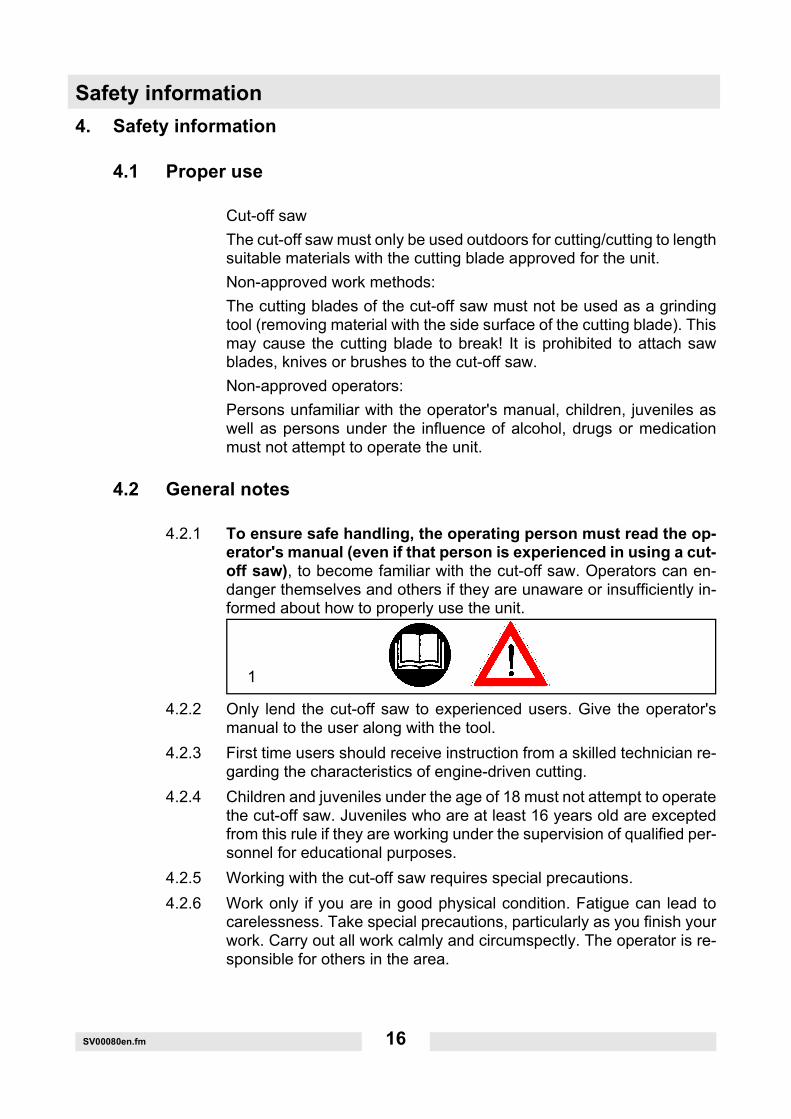
4.2.1 To ensure safe handling, the operating person must read the op-erator's manual (even if that person is experienced in using a cut-off saw), to become familiar with the cut-off saw. Operators can en-danger themselves and others if they are unaware or insufficiently in-formed about how to properly use the unit.
4.2.2 Only lend the cut-off saw to experienced users. Give the operator'smanual to the user along with the tool.
4.2.3 First time users should receive instruction from a skilled technician re-garding the characteristics of engine-driven cutting.
4.2.4 Children and juveniles under the age of 18 must not attempt to operatethe cut-off saw. Juveniles who are at least 16 years old are exceptedfrom this rule if they are working under the supervision of qualified per-sonnel for educational purposes.
4.2.5 Working with the cut-off saw requires special precautions.4.2.6 Work only if you are in good physical condition. Fatigue can lead to
carelessness. Take special precautions, particularly as you finish yourwork. Carry out all work calmly and circumspectly. The operator is re-sponsible for others in the area.
1

SV00080en.fm 17
Safety information4.2.7 Never operate the machine under the influence of alcohol, drugs, med-
ication or other substances that can impair your vision, coordinationand judgment.
4.2.8 When working with highly flammable vegetation and in dry conditionsensure that a fire extinguisher is readily available for use (danger offire).
4.2.9 Asbestos or materials that could discharge toxins may only be cut us-ing the proper safety measures and after notifying the responsible au-thorities and under their supervision or that of persons charged withthis duty. The use of dust bonding devices is strongly recommended.
4.2.10 Some dust created by power sanding sawing, grinding, drilling, andother construction activities contains chemicals known (to the State ofCalifornia) to cause cancer, birth defects or other reproductive harm.Some examples of these chemicals are:
∗ lead from lead-based paints,∗ crystalline silica from bricks and cement and other masonry products∗ arsenic and chromium from chemically treated lumber.
Your risk from these exposures varies, depending on how often you dothis type of work.To reduce your exposure to these chemicals: work in a well ventilatedarea, and work with approved safety equipment, such as those dustmasks that are specially designed to filter out microscopic particles.
4.3 Personal protective gear
4.3.1 Wear and use the following protective equipment and devices to pre-vent head, eye, hand and foot injuries as well as hearing damage.
4.3.2 Clothing should be appropriate, i.e. should be close-fitting but not re-strict your movement. When cutting metal, do not wear clothing inwhich grains of material can be caught (pants with cuffs, jackets orpants with open pockets, etc.).
4.3.3 Do not wear jewelry or clothing that can become entangled or distractthe operator from the cutting process.
2

Safety information
SV00080en.fm 18
4.3.4 Always wear a hardhat (A). Regularly check the hardhat for damageand and replace it at least every 5 years. Only use tested hardhats.
4.3.5 The hardhat face protection (B) protects the face from grinding resi-due and grains of material. To prevent eye and face injuries, alwayswear eye protection (C) or face protection when working with the cut-off saw.
4.3.6 To prevent hearing damage always wear suitable ear protection. (Earprotections (D), ear plugs, etc.). Octave band analysis by request.
4.3.7 When dry cutting stone materials that generate particulate matter(stone, concrete, etc.), properly functioning breathing protection (E)must be worn.
4.3.8 Work gloves (F) made of durable leather are part of the proper work-ing equipment and must always be worn when working with the cut-offsaw.
3
4

SV00080en.fm 19
Safety information
4.3.9 Wear non-skid, hard-toed shoes or boots (G) and leg protection whenworking with the cut-off saw. Safety shoes with protective inlays pro-tect feet from laceration and ensure that the operator is standing in se-cure position.
4.3.10 Always wear overalls (H) made of durable material that is sufficientlyfire resistant!
5
Safety information
SV00080en.fm 20
4.4 Operating fluids / Filling the tank
4.4.1 Before you fill the tank, go to a a safe and level area. It is prohibitedto fill the tank on a scaffolding, a mound of material or similar el-evated structure!
4.4.2 Turn off the engine before you fill the tank of the cut-off saw.
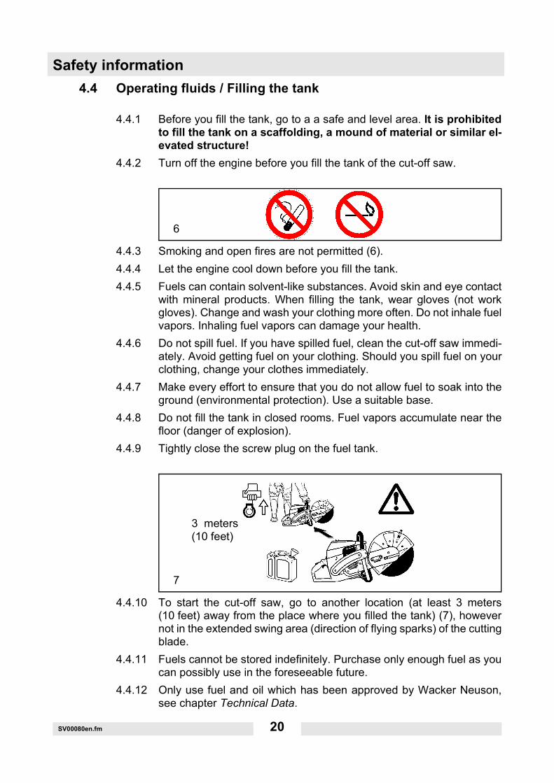
4.4.3 Smoking and open fires are not permitted (6).4.4.4 Let the engine cool down before you fill the tank.4.4.5 Fuels can contain solvent-like substances. Avoid skin and eye contact
with mineral products. When filling the tank, wear gloves (not workgloves). Change and wash your clothing more often. Do not inhale fuelvapors. Inhaling fuel vapors can damage your health.
4.4.6 Do not spill fuel. If you have spilled fuel, clean the cut-off saw immedi-ately. Avoid getting fuel on your clothing. Should you spill fuel on yourclothing, change your clothes immediately.
4.4.7 Make every effort to ensure that you do not allow fuel to soak into theground (environmental protection). Use a suitable base.
4.4.8 Do not fill the tank in closed rooms. Fuel vapors accumulate near thefloor (danger of explosion).
4.4.9 Tightly close the screw plug on the fuel tank.
4.4.10 To start the cut-off saw, go to another location (at least 3 meters(10 feet) away from the place where you filled the tank) (7), howevernot in the extended swing area (direction of flying sparks) of the cuttingblade.
4.4.11 Fuels cannot be stored indefinitely. Purchase only enough fuel as youcan possibly use in the foreseeable future.
4.4.12 Only use fuel and oil which has been approved by Wacker Neuson,see chapter Technical Data.
6
7
3 meters(10 feet)

SV00080en.fm 21
Safety information4.4.13 When preparing the correct gasoline/oil mixing ratio, first always pour
oil into the mixing container and then the gasoline.4.4.14 Transport and store fuel only in approved and specially marked canis-
ters.Do not allow children near the fuel.
4.5 Starting up
4.5.1 Do not work alone; someone must be nearby in case of an emer-gency (within calling distance).
4.5.2 When using cut-off saws in residential areas, please observe the localnoise regulations.
4.5.3 Never use the cut-off saw near inflammable materials or explo-sive gases! The cut-off saw can create sparks leading to fire orexplosion!
4.5.4 Ensure that persons (for example those assisting you) within a rangeof 30 m (100 feet) also wear protective gear (see "Personal ProtectiveGear") (8). Children or other persons must keep a distance of at least30 m (100 feet) from the work area of the cut-off saw. Be aware of anyanimals in the vicinity (9).
8= Wear protective gear
30 m (100 feet)
9

Safety information
SV00080en.fm 22
4.5.5 Before you start to work with the cut-off saw, check to see that is inproper working order and in a safe operating condition!In particular, check the following: Inspect the condition of the cuttingblade (replace immediately if the disc is cracked, bent or otherwisedamaged). Check that the disc is properly mounted, the protectivehood is locked in place, the belt guard is firmly attached, the V-belt isproperly tightened, the throttle lever moves unhindered and functionscorrectly, the handles are clean and dry and the multifunction switchworks.
4.5.6 Do not start the cut-off saw until you have completely assembled andtested it in operation. The cut-off saw must only be operated when it iscompletely assembled!
4.6 Cutting blades
4.6.1 The protective hood must always be attached. Change the cuttingblade only when the engine has been turned off!If you are using diamond-edged cutting blades, make sure you ob-serve the attached rotational direction mark.
4.6.2 Cutting blades are only designed to cut materials on their edges. Neveruse the side surfaces for grinding purposes as this can break the disc!(10).
10
min. 5 m(16 feet)
11

SV00080en.fm 23
Safety informationNOTICE:It is prohibited to change the direction (a radius of 5 m (16 feet) or less),apply lateral pressure or tilt the cut-off saw while you are cutting (11)!
4.6.3 Cutting blades must only be used to cut materials they were designedfor. Depending on the material you wish to cut (metal or concrete), youmust select the proper disc type.
4.6.4 The arbor diameter of the cutting blade must precisely fit the shaft. Ifthe arbor diameter is larger, you must use an intermediate ring as anadapter.
4.6.5 The cutting blade must be approved for freehand cutting with a400 mm (16") cutting blade diameter up to 3,850 rpm or 80 m/s(260 ft./sec), a 350 mm (14") cutting blade diameter up to 4,370 rpm or80 m/s (260 ft./sec) or a 300 mm (12") cutting blade diameter up to5,100 rpm or 80 m/s (260 ft./sec). Use only cutting blades that complywith EN 12413 or EN 13236.
4.6.6 The cutting blade must be completely undamaged (12). Test it by per-forming a sound test with a piece of wood.Always tighten the cutting blade to 30 Nm, otherwise you may distortthe cutting blade.
4.6.7 Before starting, the operator must stand at safe distance away from thecut-off saw.
12

Safety information
SV00080en.fm 24
4.6.8 Start the cut-off saw only as described in the operator's manual (13).Always set your left foot into the handle and firmly hold the bow handlegrip handle by using your thumb. Starting the machine in any other wayis not permitted.
4.6.9 When you start up the machine, support it well and hold it firmly. Thecutting blade must be freestanding.
4.6.10 A new cutting blade must be tested before you cut with it by running itat least 60 seconds at the specified maximum speed. Ensure that noone is in the extended swing area of the cutting blade.
4.6.11 When operating the cut-off saw, hold it firmly with both hands.The right hand on the rear handle, and the left hand on the bow handlegrip. Hold the grips firmly using your thumbs.
4.6.12 When you release the throttle lever, the cutting blade will contin-ue to run briefly (afterrun).
4.6.13 Always ensure that you are standing in a secure position.4.6.14 Hold the cut-off saw in such a way that you cannot inhale the exhaust
fumes. Do not work in closed rooms or in deep trenches (danger of poi-soning through exhaust fumes).
4.6.15 If you notice any changes in the way the machine operates, turn off theengine immediately.
4.6.16 You must turn off the engine before you check the V-belt tension,retighten the belt, change the cutting blade, remount the cuttingattachment (outer or center position) and eliminatemalfunctions (14).
13
*Maintenance*Filling the tank*Changing the cutting blade*Remounting the cutting attachment
*Taking a break*Transport*Shutting down14

SV00080en.fm 25
Safety information4.6.17 If you hear or feel a change in the way the machine is cutting, turn off
the engine immediately and check the cutting blade.4.6.18 During breaks and after you finish work, turn off (14) the cut-off saw
and set it down so that the cutting blade is freestanding and cannot en-danger anyone.
4.6.19 Do not lay the hot cutting blade on dry grass or onto combustible ob-jects. The muffler radiates an enormous amount of heat (danger offire).
4.6.20 NOTICE: After a wet cutting procedure, first shut off the stream of wa-ter and then let the cutting blade run another 30 seconds so that it canspin off the remaining water. This prevents corrosion.
4.7 Kickback and pulling motion
4.7.1 When working with the cut-off saw, it can kick back or suddenly pullyou.
4.7.2 Kickback can occur if the upper area of the cutting blade is used forcutting (15).
4.7.3 The cut-off saw will skid or accelerate with great force toward the op-erator (danger of injury!).To prevent kickback, observe the following:
4.7.4 Never use the area illustrated in Fig. 15 for cutting!Exercise extra caution when inserting the tool into previously madecuts!
4.7.5 A pulling motion occurs when the cut is constricted (due to a crack ora workpiece under tension).
4.7.6 The cut-off saw will skid or accelerate forward with great force (dangerof injury!).To prevent this pulling motion, observe the following:
4.7.7 Always insert the tool into previously made cuts and carry out the cut-ting process at maximum speed.
15
Safety information
SV00080en.fm 26
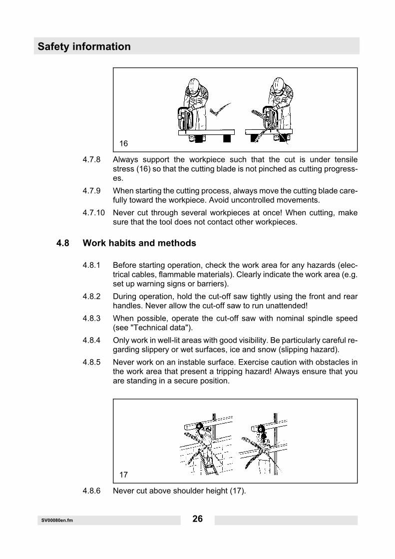
4.7.8 Always support the workpiece such that the cut is under tensilestress (16) so that the cutting blade is not pinched as cutting progress-es.
4.7.9 When starting the cutting process, always move the cutting blade care-fully toward the workpiece. Avoid uncontrolled movements.
4.7.10 Never cut through several workpieces at once! When cutting, makesure that the tool does not contact other workpieces.
4.8 Work habits and methods
4.8.1 Before starting operation, check the work area for any hazards (elec-trical cables, flammable materials). Clearly indicate the work area (e.g.set up warning signs or barriers).
4.8.2 During operation, hold the cut-off saw tightly using the front and rearhandles. Never allow the cut-off saw to run unattended!
4.8.3 When possible, operate the cut-off saw with nominal spindle speed(see "Technical data").
4.8.4 Only work in well-lit areas with good visibility. Be particularly careful re-garding slippery or wet surfaces, ice and snow (slipping hazard).
4.8.5 Never work on an instable surface. Exercise caution with obstacles inthe work area that present a tripping hazard! Always ensure that youare standing in a secure position.
4.8.6 Never cut above shoulder height (17).
16
17
SV00080en.fm 27
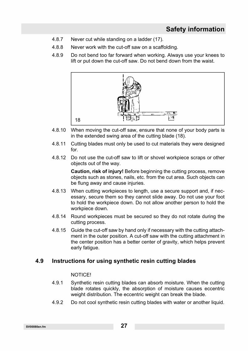
Safety information4.8.7 Never cut while standing on a ladder (17).4.8.8 Never work with the cut-off saw on a scaffolding.4.8.9 Do not bend too far forward when working. Always use your knees to
lift or put down the cut-off saw. Do not bend down from the waist.
4.8.10 When moving the cut-off saw, ensure that none of your body parts isin the extended swing area of the cutting blade (18).
4.8.11 Cutting blades must only be used to cut materials they were designedfor.
4.8.12 Do not use the cut-off saw to lift or shovel workpiece scraps or otherobjects out of the way.Caution, risk of injury! Before beginning the cutting process, removeobjects such as stones, nails, etc. from the cut area. Such objects canbe flung away and cause injuries.
4.8.13 When cutting workpieces to length, use a secure support and, if nec-essary, secure them so they cannot slide away. Do not use your footto hold the workpiece down. Do not allow another person to hold theworkpiece down.
4.8.14 Round workpieces must be secured so they do not rotate during thecutting process.
4.8.15 Guide the cut-off saw by hand only if necessary with the cutting attach-ment in the outer position. A cut-off saw with the cutting attachment inthe center position has a better center of gravity, which helps preventearly fatigue.
4.9 Instructions for using synthetic resin cutting blades
NOTICE!4.9.1 Synthetic resin cutting blades can absorb moisture. When the cutting
blade rotates quickly, the absorption of moisture causes eccentricweight distribution. The eccentric weight can break the blade.
4.9.2 Do not cool synthetic resin cutting blades with water or another liquid.
18

Safety information
SV00080en.fm 28
4.9.3 Do not expose synthetic resin cutting blades to high humidity or rain!4.9.4 Only use synthetic resin cutting blades up to their expiration date! This
date (quarter/year) is engraved on the cutting blade supporting ring.EXAMPLE: 04 / 2007With proper use and storage, this cutting blade can be used up to andincluding the 4th quarter in 2007.
4.10 Cutting metals
NOTICE!Wear proper breathing protection!Materials that could discharge toxins may only be cut after notifying theresponsible authorities and under their supervision or that of personscharged with this duty.
CAUTION!The quick rotation of the cutting blade heats and melts metals at thecontact point. As far from the cut as possible (behind it), swivel the pro-tective hood down (19) to divert flying sparks away from the operator(greater danger of fire!).
4.10.1 Determine and mark the cutting direction and bring the cutting bladeinto contact with the material, rotating at average speed. After cuttinga guide groove you can work at full throttle and higher pressure.
4.10.2 Cut only in the vertical or horizontal direction, not at an angle, whichcan break the blade.
4.10.3 The best way to achieve a square, smooth cut is to pull or reciprocatethe cut-off saw. Do not "push" the cutting blade into the material.
19
SV00080en.fm 29
Safety information
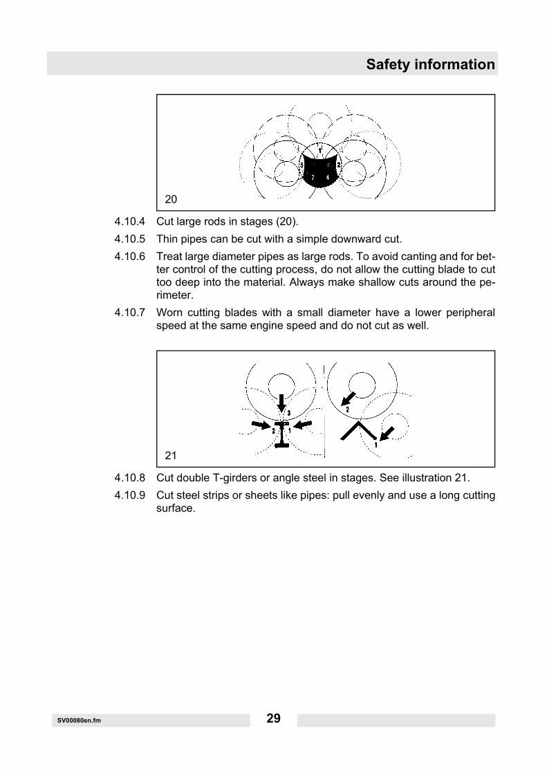
4.10.4 Cut large rods in stages (20).4.10.5 Thin pipes can be cut with a simple downward cut.4.10.6 Treat large diameter pipes as large rods. To avoid canting and for bet-
ter control of the cutting process, do not allow the cutting blade to cuttoo deep into the material. Always make shallow cuts around the pe-rimeter.
4.10.7 Worn cutting blades with a small diameter have a lower peripheralspeed at the same engine speed and do not cut as well.
4.10.8 Cut double T-girders or angle steel in stages. See illustration 21.4.10.9 Cut steel strips or sheets like pipes: pull evenly and use a long cutting
surface.
20
21

Safety information
SV00080en.fm 30
4.10.10 Always notch material that is under tension (material that is supportedor embedded in a wall) on the pressure face and then cut from the op-posite side so that the cutting blade does not get pinched (22). Securethe material that is to be cut so that it does not fall!NOTICE!In case of suspected tension, be prepared for the material to kick backand make sure you can move away, should it occur.Use extra caution in scrapyards, accident scenes or unsorted stacksof material. Material that is under tension, slipping or cracking is unpre-dictable. Secure the material that is to be cut so that it does not fall(22)! Work very carefully and only with machines that are in perfectcondition.Observe the accident prevention regulations set forth by the profes-sional liability insurance association.
4.11 Cutting stone, concrete, asbestos or asphalt
NOTICE!Wear proper breathing protection!Asbestos or materials that could discharge toxins may only be cut afternotifying the responsible authorities and under their supervision or thatof persons charged with this duty. When cutting concrete piles that areunder tension and contain metal, comply with the instructions andnorms from the respective authorities or part manufacturers. The pro-cess for cutting through reinforcing bars must be carried out in theproper order, taking the respective safety regulations into account.
22
SV00080en.fm 31
Safety informationNOTE!When cut, mortar, stone or concrete generate a great deal of fine dust.To extend the service life of the cutting blade (cooling medium), to en-able a better visual inspection and to prevent excessive dust formation,wet cutting is preferred over dry cutting. Both sides of the cutting blademust be sprayed evenly with water. You can find the right equipmentfor every wet cutting application in the Wacker Neuson product range.
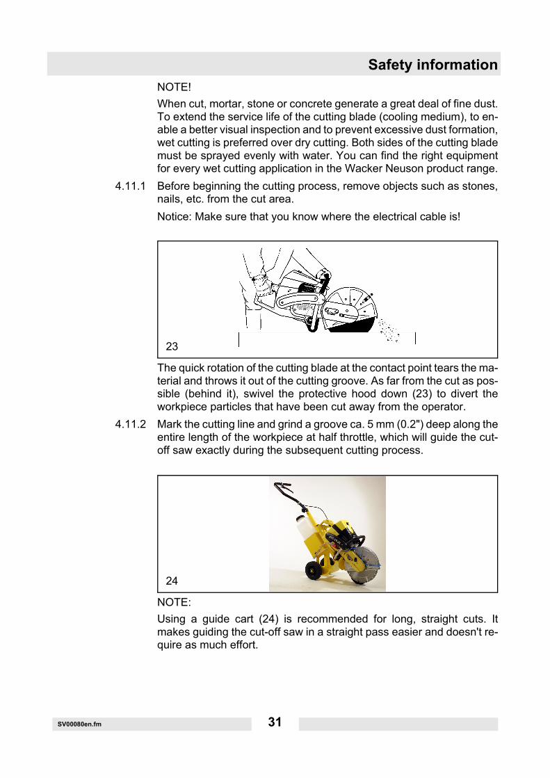
4.11.1 Before beginning the cutting process, remove objects such as stones,nails, etc. from the cut area.Notice: Make sure that you know where the electrical cable is!
The quick rotation of the cutting blade at the contact point tears the ma-terial and throws it out of the cutting groove. As far from the cut as pos-sible (behind it), swivel the protective hood down (23) to divert theworkpiece particles that have been cut away from the operator.
4.11.2 Mark the cutting line and grind a groove ca. 5 mm (0.2") deep along theentire length of the workpiece at half throttle, which will guide the cut-off saw exactly during the subsequent cutting process.
NOTE:Using a guide cart (24) is recommended for long, straight cuts. Itmakes guiding the cut-off saw in a straight pass easier and doesn't re-quire as much effort.
23
24
Safety information
SV00080en.fm 32
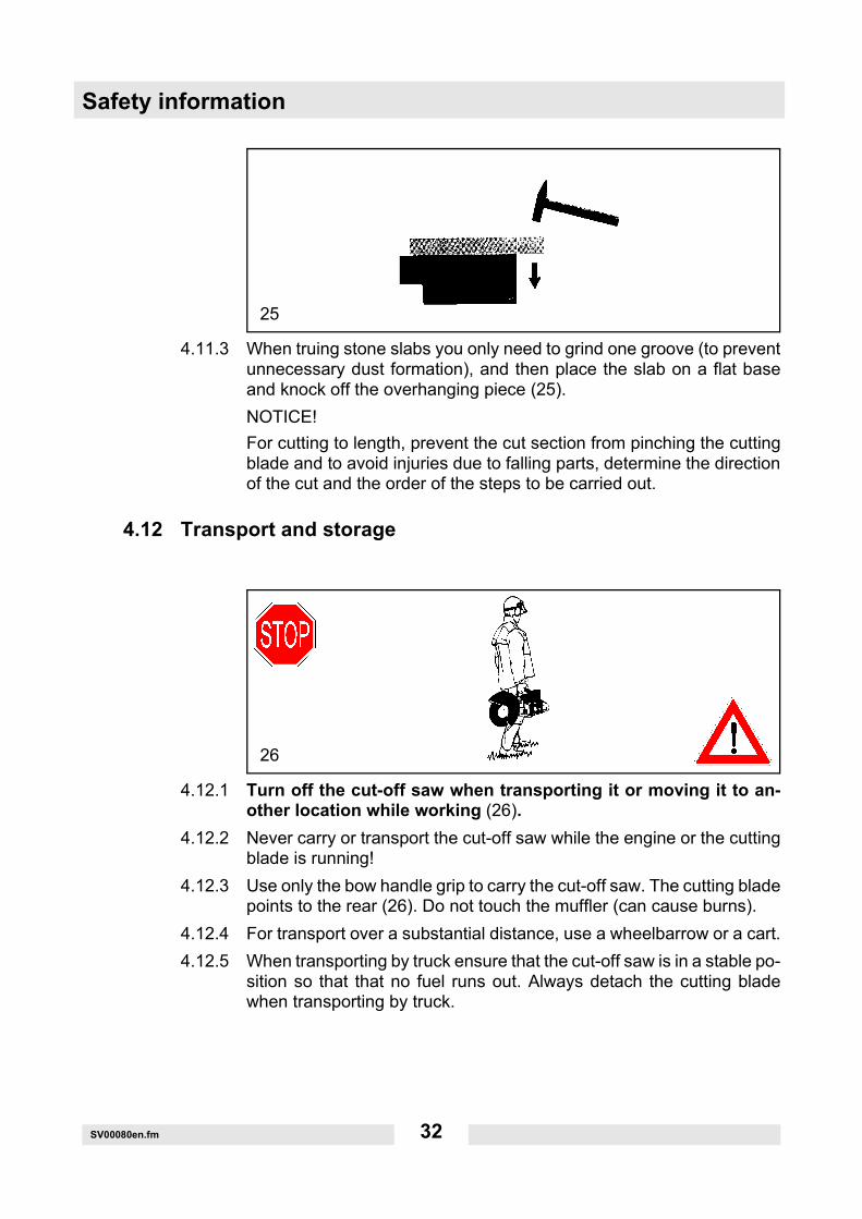
4.11.3 When truing stone slabs you only need to grind one groove (to preventunnecessary dust formation), and then place the slab on a flat baseand knock off the overhanging piece (25).NOTICE!For cutting to length, prevent the cut section from pinching the cuttingblade and to avoid injuries due to falling parts, determine the directionof the cut and the order of the steps to be carried out.
4.12 Transport and storage
4.12.1 Turn off the cut-off saw when transporting it or moving it to an-other location while working (26).
4.12.2 Never carry or transport the cut-off saw while the engine or the cuttingblade is running!
4.12.3 Use only the bow handle grip to carry the cut-off saw. The cutting bladepoints to the rear (26). Do not touch the muffler (can cause burns).
4.12.4 For transport over a substantial distance, use a wheelbarrow or a cart.4.12.5 When transporting by truck ensure that the cut-off saw is in a stable po-
sition so that that no fuel runs out. Always detach the cutting bladewhen transporting by truck.
25
26

SV00080en.fm 33
Safety information4.12.6 Store the cut-off saw securely in a dry area. Do not store it outdoors.
Always detach the cutting blade. Do not allow children near the cut-offsaw.
4.12.7 Before a long storage period and before shipping the cut-off sawmake sure to follow the "Periodic maintenance and service in-structions". Always empty the fuel tank and run the carburetorempty.
4.12.8 Proceed especially carefully when storing the cutting blades:4.12.9 Clean them and dry them well.
NOTICE: Do not clean synthetic resin cutting blades with water or other liquids!
4.12.10 Always lay them flat to store them.4.12.11 Avoid the risk of splintering or breakage by preventing contact with
moisture, frost, direct sunlight, high temperatures or temperature fluc-tuation!
4.12.12 Check the expiration date before using the synthetic resin cuttingblades again after storage (engraved on the supporting ring - quarter/year). If the expiration date has passed, the cutting blade may not beused.
4.12.13 Always check new cutting blades or those from storage for damageand test them by running them at least 60 seconds at the specifiedmaximum speed. Ensure that no one is in the extended swing of thecutting blade.
4.13 Maintenance
4.13.1 Before you carry out any maintenance work, always turn off thecut-off saw (27) and pull off the spark plug connector!
4.13.2 Check that the cut-off saw is in a safe operating condition before youstart work. Make sure that the cutting blade has been attached accord-ing to instructions. Also make sure that the cutting blade is undamagedand suited for the application at hand.
4.13.3 While operating the machine, try to produce as little noise and exhaustfumes as possible. Check the carburetor setting.
4.13.4 Clean the cut-off saw regularly.
27

Safety information
SV00080en.fm 34
4.13.5 Check the tank cap regularly to make sure it is on tightly.4.13.6 Observe the accident prevention regulations set forth by the
professional liability insurance association. Never attempt to modifythe cut-off saw! Doing so will endanger your safety!
4.13.7 Service and maintenance work must only be carried out to the extentdescribed in these operator's manual. All other procedures must beperformed by Wacker Neuson Service.
4.13.8 Use only Wacker Neuson spare parts and accessories.Use of spare parts, accessories and cutting blades not produced byWacker Neuson increases your chances of having an accident. Ifaccidents or damage that occurs with accessories not producedby Wacker Neuson exempts the manufacturer from all liability.
4.14 First Aid
A first aid kit in accordance with DIN 13164 should always be availablein the working area in case an accident occurs. Immediately replaceany materials that are removed.When requesting assistance, provide the following information:
∗ where it happened∗ what happened∗ how many are injured∗ what type of injuries∗ who is requesting assistance!
29
SV00080en.fm 35
Safety informationNOTE!If persons with circulatory problems are exposed too often to vibra-tions, the blood vessels or nervous system can be damaged.The following symptoms can occur due to vibrations experienced in thefingers, hands or wrists: Body parts can "go to sleep," tingling, pain,prickling, changes in skin color or in the skin itself. If these symptoms occur, consult a doctor.
4.15 Disposal and environmental protection
Remember our environment!Dispose of worn out or defective cutting blades according to localwaste disposal regulations. To prevent misuse, destroy the cuttingblades that can no longer be used before disposing of them.When the machine has reached the end of its service life, recycle it ordispose of it in a way that does not harm the environment. If necessary,ask your local administration for more information.

Technical data
TD00740en.fm 36
5. Technical data
1) Data takes the operating states idle and top speed equally into consideration.2) Peripheral speed at the highest engine speed. 3) Outer diameter/centre bore/thickness.4) At the working area (operator's ear).5) Only use synthetic 2-cycle engine oil of the specification JASO FC. or ISO L-EGD!
BTS 930L3 BTS 935L3
Item no. 0008987 0008988
Engine displacement cm3 (cu in) 64 (3.9)
Bore mm (in) 47 (1.85)
Stroke mm (in) 37 (1.46)
Max. performance kW (hp) 3.2 (4.4)
Max. torque Nm (ft.lbs.) 4.0 (3.0)
Idle speed rpm 2,500
Clutch engaging speed rpm 3,800
Limiting speed rpm 9,350
Nominal spindle speed rpm 4,300
Sound pressure level LpA eq according to EN 1454 1) 4) dB(A) 97
Sound power level LWA 109 dB(A)
Vibrational acceleration ah,w according to EN 1454- Bow handle grip (idle/nominal spindle speed)- Handle (idle/nominal spindle speed) m/s2
6 / 58 / 6
When using the guide cart FBTS:Vibrational acceleration ah,w according to EN 1454 (for the guide cart) m/s2
2.5
Ignition system (with maximum rpm limitation) Type Electronic
Spark plug Type NGK BPMR 7A / BOSCH WSR 6F / CHAMPION RCJ 6Y
Spark plug air gap mm (in) 0.5 (.020)
Fuel consumption at max. capacity according toISO 8893
l/h (US qt/h)
2.1(2.2)
Special consumption at max. capacity according toISO 8893
g/kWh (oz./hph)
500(13)
Fuel tank capacity l (US qt) 1.1 (1.2)
Gasoline/2-cycle oil mixing ratio 5) 50:1
Cutting blade for max. 80 m/s (260 ft/sec.) 2) mm (in) 300 / 20.0 / 53)
(12/0.787/0.2)350 / 25.4 / 53)
(14/1/0.2)
Spindle diameter mm (in) 20.0 (0.787") 25.4 (1")
Weight of cut-off saw (empty tank, without cutting blade)
kg (lb)
10.0(22)
10.2(22.5)

TD00740en.fm 37
Technical data
1) Data takes the operating states idle and top speed equally into consideration.2) Peripheral speed at the highest engine speed.3) Outer diameter/centre bore/thickness.4) At the working area (operator's ear).5) Only use synthetic 2-cycle engine oil of the specification JASO FC. or ISO L-EGD!
BTS 1030L3 BTS 1035L3
Item no. 0008989 0008990
Engine displacement cm3 (cu in) 73 (4.5)
Bore mm (in) 50 (1.97)
Stroke mm (in) 37 (1.46)
Max. performance kW (hp) 4.2 (5.6)
Max. torque Nm (ft.lbs.) 5.0 (3.7)
Idle speed rpm 2,500
Clutch engaging speed rpm 3,800
Limiting speed rpm 9,350
Nominal spindle speed rpm 4,300
Sound pressure level LpA eq according to EN 1454 1) 4)
dB(A) 99
Sound power level LWA 110 dB(A)
Vibrational acceleration ah,w according to EN 1454- Bow handle grip (idle/nominal spindle speed)- Handle (idle/nominal spindle speed) m/s2
7 / 58 / 7
When using the guide cart FBTS:Vibrational acceleration ah,w according to EN 1454 (for the guide cart) m/s2
2.5
Ignition system (with maximum rpm limitation) Type Electronic
Spark plug Type NGK BPMR 7A / BOSCH WSR 6F / CHAMPION RCJ 6Y
Spark plug air gap mm (in) 0.5 (.020)
Fuel consumption at max. capacity according toISO 8893
l/h (US qt/h) 2.7 (2.9)
Special consumption at max. capacity according toISO 8893
g/kWh (oz./hph)
500(13)
Fuel tank capacity l (US qt) 1.1 (1.2)
Gasoline/2-cycle oil mixing ratio 5) 50:1
Cutting blade for max. 80 m/s 2) mm (in)
300/20.0/53)
(12/0.787/0.2)350/25.4/53)
(14/1/0.2)
Spindle diameter mm (in) 20.0 (0.787") 25.4 (1")
Weight of cut-off saw (empty tank, without cutting blade)
kg (lb) 10.0 (22) 10.2 (22.5)

Technical data
TD00740en.fm 38
1) Data takes the operating states idle and top speed equally into consideration.2) Peripheral speed at the highest engine speed.3) Outer diameter/centre bore/thickness.4) At the working area (operator's ear).5) Only use synthetic 2-cycle engine oil of the specification JASO FC. or ISO L-EGD!
BTS 1140L3
Item no. 0610063
Engine displacement cm3 (cu in) 81 (4.9)
Bore mm (in) 52 (2.05)
Stroke mm (in) 38 (1.50)
Max. performance kW (hp) 4.5 (6.2)
Max. torque Nm (ft.lbs.) 5.2 (3.8)
Idle speed rpm 2,500
Clutch engaging speed rpm 3,800
Limiting speed rpm 9,350
Nominal spindle speed rpm 3,750
Sound pressure level LpA eq according to EN 1454 1) 4) dB(A) 98.3
Sound power level LWA 108 dB(A)
Vibrational acceleration ah,w according to EN 1454- Bow handle grip (idle/nominal spindle speed)- Handle (idle/nominal spindle speed) m/s2
5.6 / 6.38.8 / 6.0
When using the guide cart FBTS:Vibrational acceleration ah,w according to EN 1454 (for the guide cart) m/s2
2.5
Ignition system (with maximum rpm limitation) Type Electronic
Spark plug Type NGK BPMR 7A / BOSCH WSR 6F /
CHAMPION RCJ 6Y
Spark plug air gap mm (in) 0.5 (.020)
Fuel consumption at max. capacity according toISO 8893
l/h (US qt/h) 2.9 (3.2)
Special consumption at max. capacity according toISO 8893
g/kWh (oz./hph)
500(13)
Fuel tank capacity l (US qt) 1.1 (1.2)
Gasoline/2-cycle oil mixing ratio 5) 50:1
Cutting blade for max. 80 m/s 2) mm (in)
400/25.4/53)
(16/1/0.2)
Spindle diameter mm (in) 25.4 (1.0")
Weight of cut-off saw (empty tank, without cutting blade)
kg (lb) 10.6 (23.4)
T01126en.fm 39
Part identification6. Part identification
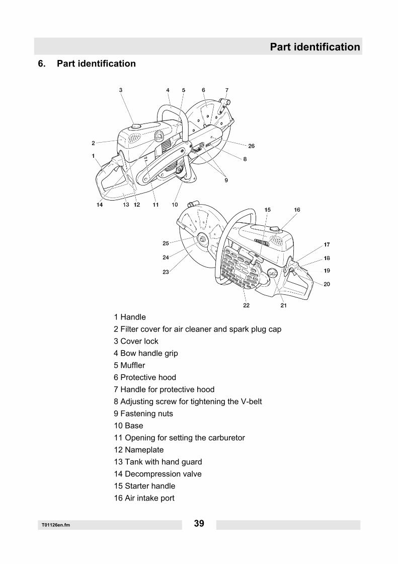
1 Handle2 Filter cover for air cleaner and spark plug cap3 Cover lock4 Bow handle grip5 Muffler6 Protective hood7 Handle for protective hood8 Adjusting screw for tightening the V-belt9 Fastening nuts10 Base11 Opening for setting the carburetor12 Nameplate13 Tank with hand guard14 Decompression valve15 Starter handle16 Air intake port

Part identification
T01126en.fm 40
17 Multifunction switch "Start/Stop" (I/O) choke18 Lock button for half throttle19 Safety switch20 Throttle lever21 Fuel tank seal22 Valve housing with starting device23 Cutting blade24 Fastening screw for cutting blade25 Clamping disc26 Opening for counterholder

T01126en.fm 41
Starting up7. Starting up
NOTICE:Before working on the cut-off saw, always turn off the en-gine, pull off the spark plug connector and wear protectivegloves!NOTICE:The cut-off saw must not be started until it has been com-pletely assembled and tested!
Always use the assembly tools included in delivery for the followingprocedures:
1 Combination wrench 13/19 mm2 Offset screwdriver3 Screwdriver for setting the carburetor4 Adapter ring (not usually included in delivery)
NOTE: Only for the BTS 1140L3 modelNo air cleaner mounted!
Before starting operation, insert the oiled foam air cleaner (prefil-ter) as shown in illustration 31! First remove the filter cover (seechapter Cleaning/Changing the air cleaner).Knead the foam air cleaner in the packaging prior insertion to ensuredistribution of the oil. Remove the packaging afterwards.
30
31

Starting up
T01126en.fm 42
7.1 Attaching the cutting blade
Set the cut-off saw onto a sturdy base and carry out the following as-sembly steps:
Check the cutting blade for damage. See SAFETY IN-FORMATION. Unscrew the screw (9) and remove theclamping disc (8). Set the cutting blade (5) onto the shaft (7).
NOTE: The arbor diameter of the cutting blade must precisely fit theshaft. If the arbor diameter is larger, you must use an adapter ring (*).
NOTICE:If you are using diamond-edged cutting blades, make sureyou observe the attached rotational direction mark!
Set the clamping disc (8) onto the shaft, screw in together with thescrew (32/9) and tighten by hand.Turn the cutting blade slowly until you can see the locking bore of theV-belt pulley bolt through the gear arm hole (10).Press the offset screwdriver (2) all the way in. The shaft is nowblocked.Firmly tighten the screw with the combination wrench (1).
NOTE: Firmly tighten the screw to 30 + 2 Nm (22 + 1.5 ft.lbs.), other-wise the cutting blade may slip while cutting.
32
33
T01126en.fm 43
Starting up7.2 Tightening the V-belt/Checking the tension
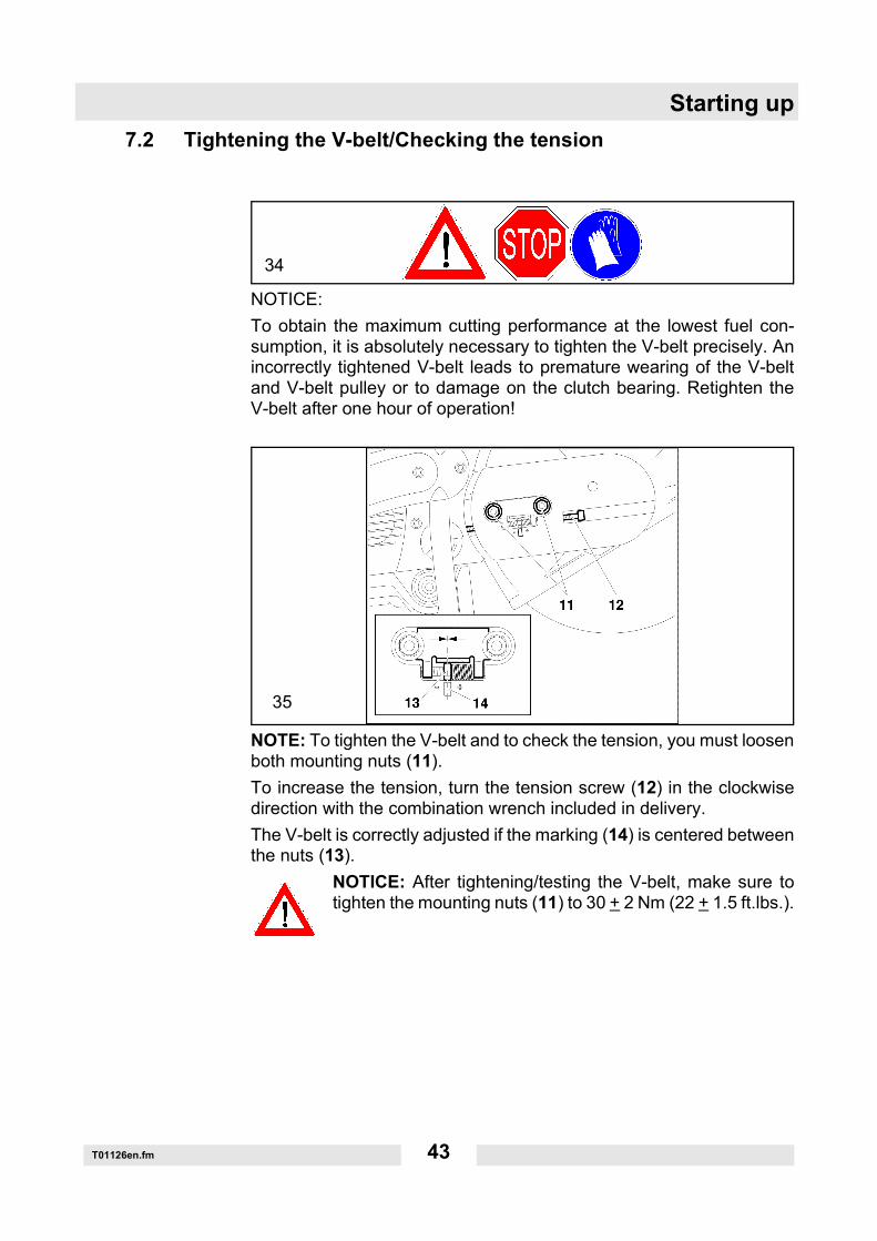
NOTICE:To obtain the maximum cutting performance at the lowest fuel con-sumption, it is absolutely necessary to tighten the V-belt precisely. Anincorrectly tightened V-belt leads to premature wearing of the V-beltand V-belt pulley or to damage on the clutch bearing. Retighten theV-belt after one hour of operation!
NOTE: To tighten the V-belt and to check the tension, you must loosenboth mounting nuts (11).To increase the tension, turn the tension screw (12) in the clockwisedirection with the combination wrench included in delivery.The V-belt is correctly adjusted if the marking (14) is centered betweenthe nuts (13).
NOTICE: After tightening/testing the V-belt, make sure totighten the mounting nuts (11) to 30 + 2 Nm (22 + 1.5 ft.lbs.).
34
35
Starting up
T01126en.fm 44
7.3 Operating fluids
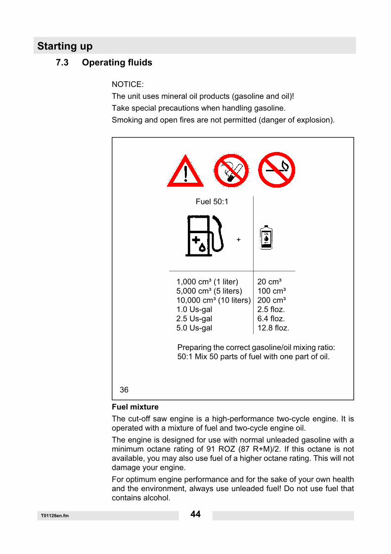
NOTICE:The unit uses mineral oil products (gasoline and oil)!Take special precautions when handling gasoline.Smoking and open fires are not permitted (danger of explosion).
Fuel mixtureThe cut-off saw engine is a high-performance two-cycle engine. It isoperated with a mixture of fuel and two-cycle engine oil.The engine is designed for use with normal unleaded gasoline with aminimum octane rating of 91 ROZ (87 R+M)/2. If this octane is notavailable, you may also use fuel of a higher octane rating. This will notdamage your engine.For optimum engine performance and for the sake of your own healthand the environment, always use unleaded fuel! Do not use fuel thatcontains alcohol.
36
Fuel 50:1
+
1,000 cm³ (1 liter) 20 cm³5,000 cm³ (5 liters) 100 cm³10,000 cm³ (10 liters) 200 cm³1.0 Us-gal 2.5 floz.2.5 Us-gal 6.4 floz.5.0 Us-gal 12.8 floz.
Preparing the correct gasoline/oil mixing ratio:50:1 Mix 50 parts of fuel with one part of oil.
T01126en.fm 45
Starting upTo lubricate the engine, use a synthetic oil for two-stroke aircooledengines (quality grade JASO FC or ISO-L-EGD), which has to beadded to the fuel.NOTE: To prepare the fuel-oil mixture, always premix the prescribedamount of oil volume with half of the fuel volume and then add the re-maining amount of fuel. Before you fill the tank, always shake the fin-ished mixture well.NOTICE: Open the cap of the fuel tank carefully since there may bepressure present!It is not a good idea to increase the oil percentage of the two-cycle mix-ture for beyond the specified mixing ratio for any reason. This will in-crease the amount of combustion residue which pollutes theenvironment and also clogs the exhaust port in the cylinder and themuffler. Furthermore, this also increases fuel consumption and reduc-es engine performance.WARNING!FUELS WITH MORE THAN 10% ETHANOL ARE NOT APPROVEDFOR USE IN Wacker Neuson 2-STROKE ENGINES!Use of alternative fuels, such as E-20 (20% ethanol), E-85 (85% etha-nol) or any fuels not meeting Wacker Neuson requirements are not ap-proved for use in this engine!USE OF ALTERNATIVE FUELS CAN CAUSE THE FOLLOWINGPROBLEMS:Poor engine performance, loss of power, overheating, fuel vapor lock,improper clutch engagement, premature deterioration of fuel lines,premature deterioration of gaskets, premature deterioration of carbu-retors.USING ALTERNATIVE FUELS AND/OR 2-STROKE OILS NOT AC-CORDING TO JASO FC OR ISO-L-EGD IN THIS 2-STROKE ENGINEWILL VOID YOUR ENGINE WARRANTY!
7.4 Storing fuel
Fuels cannot be stored indefinitely. Fuel and fuel mixtures age due toevaporation, particularly under the influence of high temperatures.Fuel and fuel mixtures that have been stored for too long can lead toproblems with starting and engine damage. Purchase only enough fuelfor a few months. Mixed fuels for use at high temperatures should beused within 6-8 weeks.Store fuel only in approved containers in cool and secure areas!

Starting up
T01126en.fm 46
AVOID CONTACT WITH SKIN AND EYES!Mineral products and oils scour your skin. If used repeatedly and overtime, they will dry out your skin. This could develop into one of variousskin diseases. In addition, allergic reactions are also possible.Oil in your eyes can cause irritations. If you get oil into your eye, rinseit out immediately with clean water.If irritation continues, consult a physician immediately!
37

T01126en.fm 47
Starting up7.5 Filling the tank
NOTICE: STRICTLY FOLLOW THE SAFETY INFORMATION!Fuels must be handled carefully and prudently.Only when the engine is turned off and has cooled down!Clean the filling area so that no dirt can get into the tank.Set the machine on its side on a flat base.Screw off the tank cap and pour in the fuel mixture. Pour it in carefullyto avoid spilling the fuel mixture.Tightly screw the tank cap back on.Clean the tank cap and surrounding area after you are finished! Neverstart or operate the unit at the location where you filled the tank! Shouldyou spill fuel on your clothing, change your clothes immediately.
Fuel mixture38

Starting up
T01126en.fm 48
7.6 Starting the engine
This model is fitted with a semiautomatic decompression valve (1) tomake starting easier. Press the rubber cover until you can feel it en-gage. This pushes in the decompression valve behind it. This in turnreduces the compression, so that it takes less force to pull the startercord to accelerate the engine to its starting speed.The high pressure in the combustion chamber after the first ignition au-tomatically closes the decompression valve.
NOTICE:Strictly follow the SAFETY INFORMATION.The cut-off saw must not be started until it has been completely as-sembled and tested!Take it at least 3 m (10 feet) away from the place where you filled thetank!
39
if
required
40
3 meters(10 feet)
T01126en.fm 49
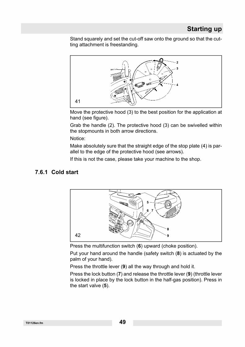
Starting upStand squarely and set the cut-off saw onto the ground so that the cut-ting attachment is freestanding.
Move the protective hood (3) to the best position for the application athand (see figure).Grab the handle (2). The protective hood (3) can be swivelled withinthe stopmounts in both arrow directions.Notice:Make absolutely sure that the straight edge of the stop plate (4) is par-allel to the edge of the protective hood (see arrows).If this is not the case, please take your machine to the shop.
7.6.1 Cold start
Press the multifunction switch (6) upward (choke position).Put your hand around the handle (safety switch (8) is actuated by thepalm of your hand).Press the throttle lever (9) all the way through and hold it.Press the lock button (7) and release the throttle lever (9) (throttle leveris locked in place by the lock button in the half-gas position). Press inthe start valve (5).
41
42
Starting up
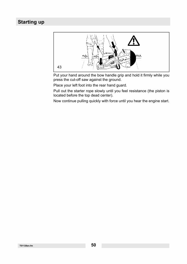
T01126en.fm 50
Put your hand around the bow handle grip and hold it firmly while youpress the cut-off saw against the ground.Place your left foot into the rear hand guard.Pull out the starter rope slowly until you feel resistance (the piston islocated before the top dead center).Now continue pulling quickly with force until you hear the engine start.
43
T01126en.fm 51
Starting upNotice: Do not pull out the starter rope more than 50 cm (20") and letit rewind slowly by hand, not letting it go.Depress decompression valve (5) again.Press the multifunction switch (42/6) to the "I" position.Pull the starter rope again until the engine runs.Once the engine is running, tip the throttle lever (42/9) so that the lockbutton (42/7) snaps out and the engine idles.
7.6.2 Warm start
As described under cold start, however without pressing the multifunc-tion switch (42/6) in the choke position.
7.7 Turning off the engine
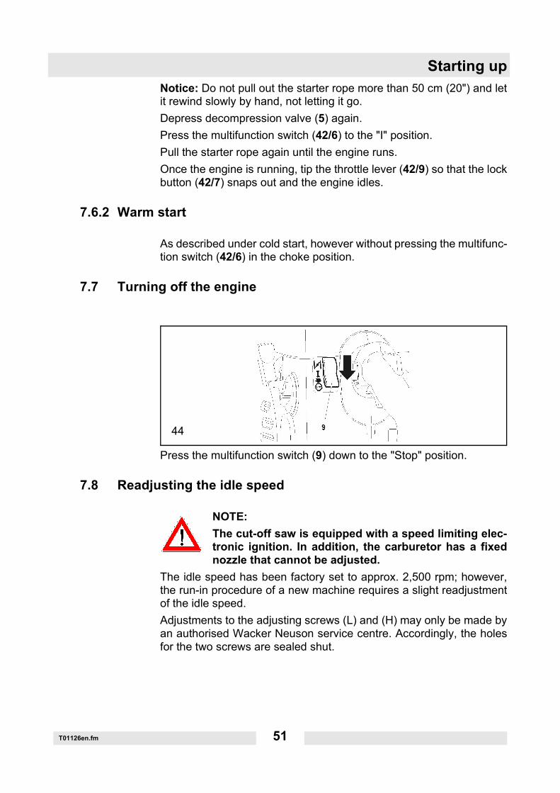
Press the multifunction switch (9) down to the "Stop" position.
7.8 Readjusting the idle speed
NOTE: The cut-off saw is equipped with a speed limiting elec-tronic ignition. In addition, the carburetor has a fixednozzle that cannot be adjusted.
The idle speed has been factory set to approx. 2,500 rpm; however,the run-in procedure of a new machine requires a slight readjustmentof the idle speed.Adjustments to the adjusting screws (L) and (H) may only be made byan authorised Wacker Neuson service centre. Accordingly, the holesfor the two screws are sealed shut.
44

Starting up
T01126en.fm 52
The following steps are required to correctly set the idle speed:Start the engine and let it warm up (approx. 3 - 5 minutes).
Set the speed for the idle position with the screwdriver that was includ-ed in delivery. Readjust the idle speedIf the cutting blade rotates when the engine is running, screw the stopscrews (2) for the choke outward until the cutting blade no longer ro-tates. If the emgine stops when idling, turn the screw back in some-what.
Turn off the engine
46
47

T01127en.fm 53
Maintenance work8. Maintenance work
NOTICE:Only use spare parts from Wacker Neuson! Non-compliance willexempt the manufacturer from all liability.
NOTICE:When working on the cut-off saw, always turn off the engine, removethe cutting blade, pull off the spark plug connector and wear protectivegloves!
NOTICE:The cut-off saw must not be started until it has been completely as-sembled and tested!
NOTE:For your safety, regular checks and maintenance must be carried outat a Wacker Neuson service station because many parts not discussedin this operator's manual are important safety devices and, like allparts, are also subject to wear.
NOTICE:If the cutting blade breaks during the cutting process, beforestarting the machine again it must be serviced in a WackerNeuson shop!
48

Maintenance work
T01127en.fm 54
8.1 Replacing the V-belt
Loosen the nuts (3).Loosen the tension screw (1) (counterclockwise) until you see thescrew end (2) in the gap.Release the screw (detail X, only on BTS 1140L3) and remove it.Unscrew the nuts (3) and remove the cap (4).Unscrew the screws (5) and (7) and take off the side brace (6).
NOTE:Screw (5) is longer than screws (7). Observe the installationposition during assembly!
Loosen the screws (8) and take off the crankcase cover (9).Remove the old V-belt (10) or any leftover V-belt material. Clean theinside of the transmission with a small brush.Insert the new V-belt.
NOTE:Mount the crankcase cover (9), the side brace (50/6) and the cover(50/4) in the reverse order.Tighten the V-belt, see Chapter "Tightening the V-belt/Checking thetension".
50
51
T01127en.fm 55
Maintenance work8.2 Cleaning the protective hood
With time, material deposits will form on the inside of the protectivehood (particularly when wet cutting). Under certain circumstances,these deposits can hinder the free rotation of the cutting blade.Detach the cutting blade and thrust washer and remove the materialdeposits on the inside with a wood strip or similar tool.Wipe off the shaft and all disassembled parts with a clean cloth.
8.3 Cleaning/Changing the air cleaner
NOTICE:Before cleaning the air cleaner, turn off the engine! Never clean the aircleaner with compressed air! Do not clean the prefilter or the internalfilter with fuel!The engine's service life depends on the condition and the regularmaintenance of the filter elements. Not regularly cleaning or maintain-ing the engine leads to excessive wear!Replace a damaged air cleaner immediately! Torn pieces of fabric andlarge dirt particles can destroy the engine. If possible, do not work industy conditions! The particulate matter generated when dry cuttingconcrete and stone endangers the operator's health and shortens theengine's service life. If possible, carry out cutting operations for con-crete and stone with water to bind dust particles together.
52
NOTE: See chapter "Attaching the cuttingblade" for information on assembling the cut-ting blade.

Maintenance work
T01127en.fm 56
Turn the cover lock (11) to the "unlocked " position and carefully re-move the filter cover (12).Two sealing rings (54/15) are located between the filter cover (12) andthe hood (54/14).
Loosen the screws (13) and take off the hood (14).Clean the sealing rings (15) using a small brush and check for signs ofdamage.
Take the prefilter (17) out of the filter cover.Pull the air cleaner cartridge (18) out of the hood.Take the internal filter (16) off the suction head.Note:Protect the carburetor to prevent dirt from falling into it!Put the multifunction switch in the "Choke" position or cover the carbu-retor with a clean cloth.
53
54
55
T01127en.fm 57
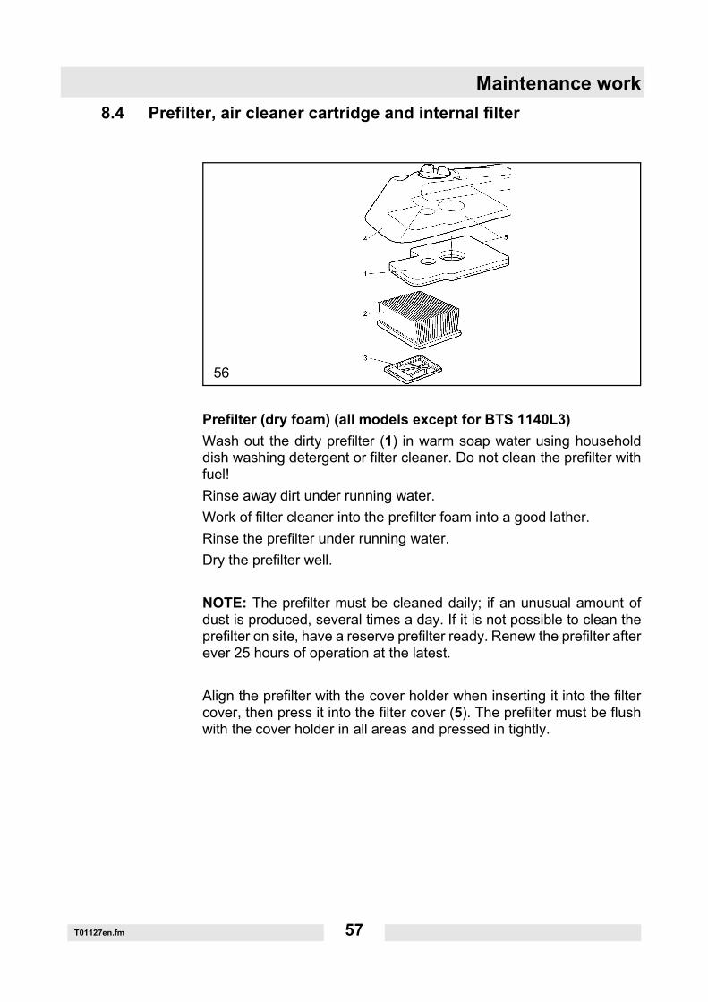
Maintenance work8.4 Prefilter, air cleaner cartridge and internal filter
Prefilter (dry foam) (all models except for BTS 1140L3)Wash out the dirty prefilter (1) in warm soap water using householddish washing detergent or filter cleaner. Do not clean the prefilter withfuel!Rinse away dirt under running water.Work of filter cleaner into the prefilter foam into a good lather.Rinse the prefilter under running water.Dry the prefilter well.
NOTE: The prefilter must be cleaned daily; if an unusual amount ofdust is produced, several times a day. If it is not possible to clean theprefilter on site, have a reserve prefilter ready. Renew the prefilter afterever 25 hours of operation at the latest.
Align the prefilter with the cover holder when inserting it into the filtercover, then press it into the filter cover (5). The prefilter must be flushwith the cover holder in all areas and pressed in tightly.
56

Maintenance work
T01127en.fm 58
Prefilter (foam with air cleaner oil) (only BTS 1140L3)
Replacement (after cutting with excessive dust formation):• daily• or at least after 4 hours of operation• or at least after filling the tank 8 times• or at least after using 8 liters of fuel mixture
Replacement (after wet cutting/after cutting steel):• weekly• or at least after 25 hours of operation• or at least after filling the tank 50 times• or at least after using 55 liters of fuel mixture
Knead the foam air cleaner in the packaging prior insertion to ensuredistribution of the oil. Remove the packaging afterwards.Align the prefilter with the cover holder when inserting it into the filtercover, then press it into the filter cover (5). The prefilter must be flushwith the cover holder in all areas and pressed in tightly.

T01127en.fm 59
Maintenance workInternal filter (all models)Wash out the dirty internal filter (3) in warm soap water using house-hold dish washing detergent or filter cleaner.
Air cleaner cartridge (all models)NOTICE:The air cleaner cartridge (2) filters the intake air through fine paper fil-ter lamella. Thus never wash out the cartridge or clean it with com-pressed air.
Clean the air cleaner cartridge once a week.Expand the lamella of the air cleaner cartridge slightly, lay it on a cleanpad and carefully tap against it.Replace the air cleaner cartridge after every 100 hours of operation.Replace it immediately if you notice a drop in power, a drop in enginespeed or smoke in the exhaust fumes.Before assembling the filter system, check whether dirt particles havefallen into the air intake port. If necessary, remove the dirt particles.
Maintenance work
T01127en.fm 60
8.5 Replacing the spark plug
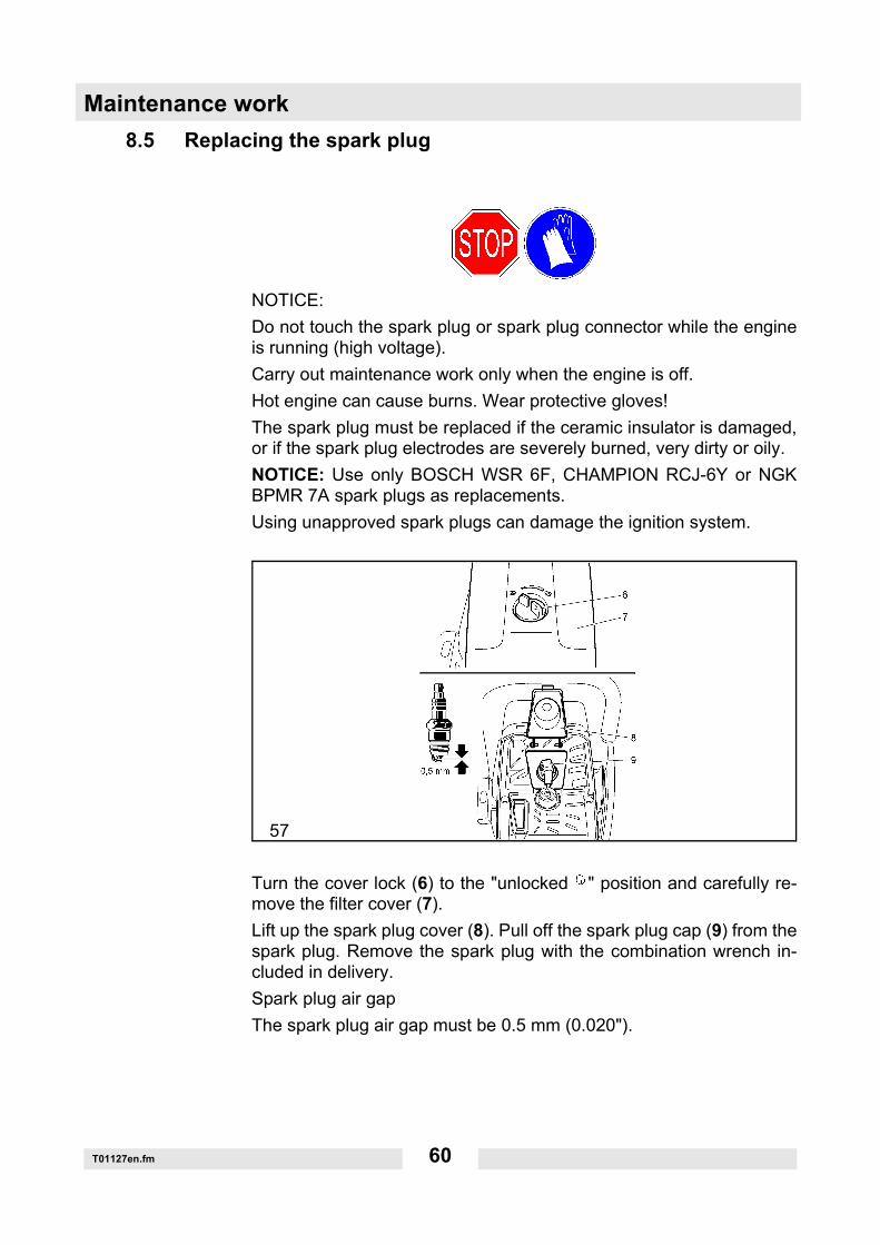
NOTICE:Do not touch the spark plug or spark plug connector while the engineis running (high voltage).Carry out maintenance work only when the engine is off.Hot engine can cause burns. Wear protective gloves!The spark plug must be replaced if the ceramic insulator is damaged,or if the spark plug electrodes are severely burned, very dirty or oily.NOTICE: Use only BOSCH WSR 6F, CHAMPION RCJ-6Y or NGKBPMR 7A spark plugs as replacements.Using unapproved spark plugs can damage the ignition system.
Turn the cover lock (6) to the "unlocked " position and carefully re-move the filter cover (7).Lift up the spark plug cover (8). Pull off the spark plug cap (9) from thespark plug. Remove the spark plug with the combination wrench in-cluded in delivery.Spark plug air gapThe spark plug air gap must be 0.5 mm (0.020").
57

T01127en.fm 61
Maintenance work8.6 Checking the ignition spark
Insert the combination wrench (9) between the hood and cylinder, asshown in the figure.NOTICE!Do not insert the wrench into the spark plug hole; just make contactwith the cylinder (otherwise you may damage the engine).Press the unscrewed spark plug (10), with the spark plug terminal capfirmly attached, against the wrench using insulated pliers (away fromthe spark plug hole!).Press the multifunction switch (11) to the "I" position.Pull out the starter rope firmly.If the spark plug is functioning properly, you must see a spark plug be-tween the electrodes.
58
Maintenance work
T01127en.fm 62
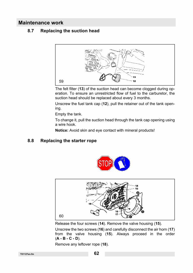
8.7 Replacing the suction head
The felt filter (13) of the suction head can become clogged during op-eration. To ensure an unrestricted flow of fuel to the carburetor, thesuction head should be replaced about every 3 months.Unscrew the fuel tank cap (12), pull the retainer out of the tank open-ing.Empty the tank.To change it, pull the suction head through the tank cap opening usinga wire hook.Notice: Avoid skin and eye contact with mineral products!
8.8 Replacing the starter rope
Release the four screws (14). Remove the valve housing (15).Unscrew the two screws (16) and carefully disconnect the air horn (17)from the valve housing (15). Always proceed in the order(A - B - C - D).Remove any leftover rope (18).
59
60
T01127en.fm 63
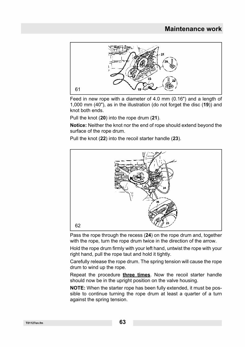
Maintenance work
Feed in new rope with a diameter of 4.0 mm (0.16") and a length of1,000 mm (40"), as in the illustration (do not forget the disc (19)) andknot both ends.Pull the knot (20) into the rope drum (21).Notice: Neither the knot nor the end of rope should extend beyond thesurface of the rope drum.Pull the knot (22) into the recoil starter handle (23).
Pass the rope through the recess (24) on the rope drum and, togetherwith the rope, turn the rope drum twice in the direction of the arrow.Hold the rope drum firmly with your left hand, untwist the rope with yourright hand, pull the rope taut and hold it tightly.Carefully release the rope drum. The spring tension will cause the ropedrum to wind up the rope.Repeat the procedure three times. Now the recoil starter handleshould now be in the upright position on the valve housing.NOTE: When the starter rope has been fully extended, it must be pos-sible to continue turning the rope drum at least a quarter of a turnagainst the spring tension.
61
62
Maintenance work
T01127en.fm 64
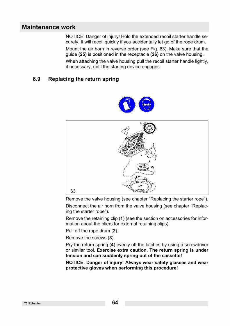
NOTICE! Danger of injury! Hold the extended recoil starter handle se-curely. It will recoil quickly if you accidentally let go of the rope drum.Mount the air horn in reverse order (see Fig. 63). Make sure that theguide (25) is positioned in the receptacle (26) on the valve housing.When attaching the valve housing pull the recoil starter handle lightly,if necessary, until the starting device engages.
8.9 Replacing the return spring
Remove the valve housing (see chapter "Replacing the starter rope").Disconnect the air horn from the valve housing (see chapter "Replac-ing the starter rope").Remove the retaining clip (1) (see the section on accessories for infor-mation about the pliers for external retaining clips).Pull off the rope drum (2).Remove the screws (3).Pry the return spring (4) evenly off the latches by using a screwdriveror similar tool. Exercise extra caution. The return spring is undertension and can suddenly spring out of the cassette!NOTICE: Danger of injury! Always wear safety glasses and wearprotective gloves when performing this procedure!
63

T01127en.fm 65
Maintenance workReplacement return springs are delivered already under tension in thehousing. CAUTION. The spring can snap out. A released spring canbe reinserted as in the illustration (Make sure to note the rotation di-rection!)Apply a light coat of multipurpose grease to the new return spring (4)before you install it in the valve housing. Insert the return spring (4) andpress gently against it so that the tabs (5) snap into the holders. Screwin the screw (3) and tighten only slightly. When attaching the ropedrum, turn it slightly until it you feel it snap into place. Mount the retain-ing clip. Wind up the starter rope (see chapter "Replacing the starterrope"). Do not lubricate the rope drum (2) or the journals!Attach the air horn (see chapter "Replacing the starter rope"). When at-taching the valve housing pull the recoil starter handle lightly, if neces-sary, until the starting device engages.
8.10 Cutting attachment in the center/outer position
NOTE: The cutting attachment is mounted at the factory for operationin the center position (1). The cutting attachment can be mounted inthe outer position (2) to maneuver around obstacles that are very closeto the cutting line (for curbs, or brick walls). Use the outer position forguiding the cut-off saw by hand only for the work at hand. Afterwards,mount the cutting attachment back to the center position. A cut-off sawwith the cutting attachment in the center position has a better center ofgravity, which helps prevent early fatigue.
64

Maintenance work
T01127en.fm 66
8.11 Remounting the cutting attachment
Loosen the nuts (5). Loosen the tension screw (3) (counterclockwise) until you see thescrew end (4) in the gap. Release the screw (detail X, only on BTS1140L3) and remove it. Unscrew the nuts (5) and remove the cover (6).
Pry out the stop pin (8) with the combination wrench (9) far enough, asshown in the figure, so that you are able to turn the protective hood(11).
65
66

T01127en.fm 67
Maintenance workNOTE: When the stop pin (8) has been pulled out, the rotary stop (7)is deactivated. This makes it possible to turn the protective hood (11)beyond the rotary stop (7).Unscrew the handle (10) and turn the protective hood (11), as shownin the figure.Detach the V-belt (12) and remove the cutting attachment.
Press the cutting attachment (13) to the outer position against the geararm receptacle.Guide the V-belt (14) over the V-belt pulley (15).
Place the cover (16) on top.Screw on the nuts (17) and tighten by hand.Tighten the V-belt, see Chapter "Tightening the V-belt/Checking thetension".Screw in the screw (detail X, only on BTS 1140L3) and tighten it.Tighten the nuts (17) securely with the combination wrench.Reattach the handle (18) as in the illustration.NOTICE:Each time you modify the cutting attachment, this will change the cut-ting blade's direction of rotation!Diamond-edged cutting blades must be mounted according to the di-rection of rotation!
67
68
Maintenance work
T01127en.fm 68
8.12 Replacing/cleaning the spark arrester screen
The spark arrester screen should be checked and cleaned regularly.
Models without catalytic converter
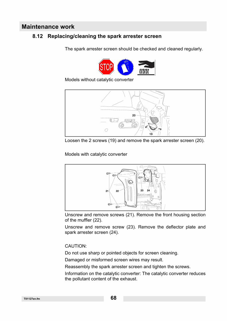
Loosen the 2 screws (19) and remove the spark arrester screen (20).
Models with catalytic converter
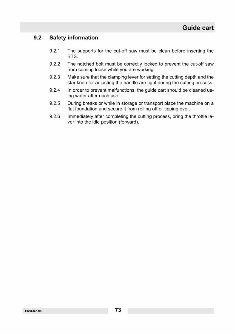
Unscrew and remove screws (21). Remove the front housing sectionof the muffler (22).Unscrew and remove screw (23). Remove the deflector plate andspark arrester screen (24).
CAUTION:Do not use sharp or pointed objects for screen cleaning.Damaged or misformed screen wires may result.Reassembly the spark arrester screen and tighten the screws.Information on the catalytic converter: The catalytic converter reducesthe pollutant content of the exhaust.
19
20
21 22 23 24

T01127en.fm 69
Maintenance work8.13 Periodic maintenance and service instructions
The maintenance work described below must be regularly carried outin to ensure a long service life, prevent damage and ensure that thesafety devices function properly. Warranty claims will only be autho-rized if this work is carried out properly when scheduled. Non-compli-ance can cause accidents!Users of cut-off saws are only permitted to carry out the maintenanceand care procedures described in this operator's manual. All other pro-cedures may only be carried out by a Wacker Neuson service station.
General Entire cut-off saw Clean the outside and check for damage. If damage is discovered, have it repair by quali-fied personnel immediately.
Cutting blade, clutch
Check on a regular basis for signs of damage and wear.
Protective hood Clean, check position.
Each time before startup
Cutting blade Check for damage and whether the correct cutting blade is mounted for the application at hand.
V-belt Check the V-belt tension.
Multifunction switch, safety switch, throttle lever
Functional check.
Fuel tank cap Check for leakage.
Daily Prefilter Clean (replace after every 25 hours of opera-tion and more often if necessary).
Idle speed Check (cutting blade must not rotate).
Weekly Starter housing Clean to ensure a proper flow of cooling air.
Starter rope Check for damage.
V-belt Check for signs of damage and wear.
Air cleaner car-tridge
Clean (replace after every 100 hours of opera-tion).
Spark plug Check and replace as needed.
Muffler Check tightness of mounting, clean or replace spark arrester screen if necessary

Maintenance work
T01127en.fm 70
Quarterly Suction head Replace.
Fuel tank Clean.
Bearing, clutch drum
Clean and regrease.
Storage Entire cut-off saw Clean the outside and check for damage. If damage is discovered, have it repair by quali-fied personnel immediately.
Cutting blade Disassemble and clean.
Fuel tank Empty and clean.
Carburetor Run empty.

T01127en.fm 71
Maintenance work8.14 Troubleshooting
Malfunction System Observation Cause
Cutting blade does not start
Clutch Engine is run-ning
Clutch is damaged.
Cutting blade rotates when engine is idling
Carburetor Cutting blade is running
Idle setting incorrect.
Clutch Clutch is blocked.
V-belt Belt has insufficient tension, V-belt is worn.
Engine will not start or is hard to start
Ignition sys-tem
There is an igni-tion spark
Malfunction in the fuel sup-ply, compression system, mechanical fault.
No ignition spark
STOP switch was actuated, fault or short-circuit in the cable, spark plug connector or spark plug is defective.
Fuel supply Fuel tank is full Choke is in the wrong posi-tion, carburetor is defective, suction head is dirty, fuel line is kinked or interrupted.
Compression system
Inside the machine
Cylinder base gasket is defective, oil seals are dam-aged or the piston ring is damaged.
Outside of the machine
The spark plug does not make an airtight seal.
Mechanical faults
Starter does not engage
Spring in the starter is bro-ken, broken parts within the engine.
Problems with warm start
Carburetor Fuel in tank, there is an igni-tion spark
Carburetor setting is incor-rect.
Engine starts, but goes out again immedi-ately
Fuel supply Fuel in the tank Idle setting incorrect, suc-tion head or carburetor is dirty. Tank venting is defec-tive, fuel supply interrupted, cable is damaged, STOP switch is damaged, decom-pression valve.
Insufficient power
This may affect several systems
Machine runs in idle
Air cleaner is dirty, carbure-tor setting is incorrect, muf-fler is clogged, exhaust port in the cylinder is clogged.Belt has insufficient tension, V-belt is worn.

Guide cart
T00964en.fm 72
9. Guide cart
9.1 Application
The Wacker Neuson guide cart makes it easier to move the cut-off sawin a straight line. It allows operators to work without fatigue and can beadjusted based on body height. The cut-off saw can be operated withthe cutting attachment in either the center or outer position.Fitting the tank with an angular fuel tank filler neck is recommendedwhen using the guide cart to make refueling easier.The guide cart is equipped with a water tank and a water sprayer tobind dust particles together during the cutting process and to cool thecutting blade.There are notches in the clamping lever to make it easier to set the cut-ting depth. One notch equals 10 mm cutting depth.
T00964en.fm 73
Guide cart9.2 Safety information
9.2.1 The supports for the cut-off saw must be clean before inserting theBTS.
9.2.2 The notched bolt must be correctly locked to prevent the cut-off sawfrom coming loose while you are working.
9.2.3 Make sure that the clamping lever for setting the cutting depth and thestar knob for adjusting the handle are tight during the cutting process.
9.2.4 In order to prevent malfunctions, the guide cart should be cleaned us-ing water after each use.
9.2.5 During breaks or while in storage or transport place the machine on aflat foundation and secure it from rolling off or tipping over.
9.2.6 Immediately after completing the cutting process, bring the throttle le-ver into the idle position (forward).

Signs
SK00658en.fm 74
10. Signs
1 Safety protective hood
2 Gasoline/oil mixing ratio
3 Safety hood


