GAV 2.0 ® GAV 2.0 ® LP This Instructions for Use is NOT intended for United State users. Please discard. The Instructions for Use for United States users can be obtained by visiting our website at www.aesculapusa.com and clicking the "Products" menu. If you wish to obtain a paper copy of the Instructions for Use, you may request one by contacting your local Aesculap representative or Aesculap's customer service at 1-800-282-9000. A paper copy will be provided to you upon request at no additional cost. US www.miethke.com Gebrauchsanweisung | Instructions for use | Instrucciones de manejo Mode d’emploi | Istruzioni per l’uso | Instruções de utilização FR GB ES IT PT DE
Transcript
GAV 2.0 ®
GAV 2.0 ® LP
This Instructions for Use is NOT intended for United State users. Please discard. The Instructions for Use for United States users can be obtained by visiting our website at www.aesculapusa.com and clicking the "Products" menu. If you wish to obtain a paper copy of the Instructions for Use, you may request one by contacting your local Aesculap representative or Aesculap's customer service at 1-800-282-9000. A paper copy will be provided to you upon request at no additional cost.
US
www.miethke.com
Gebrauchsanweisung | Instructions for use | Instrucciones de manejo Mode d’emploi | Istruzioni per l’uso | Instruções de utilização FR
GB ES
IT PT
DE
3
GEBRAUCHSANWEISUNG |GAV 2.0 DE
INHALTSVERZEICHNIS
INDIKATION 4
TECHNISCHE BESCHREIBUNG 4
ARBEITSWEISE DES VENTILS 4
AUSWAHL DER GEEIGNETEN DRUCKSTUFE 5
DRUCKSTUFENERKENNUNG IM RÖNTGENBILD 5
MÖGLICHE SHUNTKOMPONENTEN 6
SCHLAUCHSYSTEME 6
IMPLANTATION 6
VENTILPRÜFUNG 7
DRUCK-FLOW-CHARAKTERISTIK 8
VORSICHTSMASSNAHMEN UND KONTRAINDIKATIONEN 9
FUNKTIONSSICHERHEIT UND VERTRÄGLICHKEIT MIT DIAGNOSTISCHEN VERFAHREN 9
NEBEN- UND WECHSELWIRKUNGEN 9
STERILISATION 9
FORDERUNGEN DER MDD (RL 93/42/EWG) 9
MEDIZINPRODUKTEBERATER 10
VARIANTEN 10
4 5
| GEBRAUCHSANWEISUNG GAV 2.0 GEBRAUCHSANWEISUNG |GAV 2.0DE DE
1
2
3
4
INDIKATION
Das GAV 2.0 dient zur Liquordrainage bei der Behandlung des Hydrocephalus.
TECHNISCHE BESCHREIBUNG
Das GAV 2.0 ist ein aus Titan gefertigtes Ven-til. Es besteht aus einer Kugel-Konus-Einheit sowie einer Gravitationseinheit. Auf diese Wei-se kann in jeder Körperposition ein physiolo-gischer Hirndruck (IVP) erreicht werden.
Im proximalen Teil des GAV 2.0 gewährleistet eine Mikrospiralfeder (1) den Öffnungsdruck der Kugel-Konus-Einheit. Die Gravitationseinheit im distalen Teil des Ventils besteht aus einer Tantalkugel (2), die den Öffnungsdruck dieser Einheit bestimmt, sowie einer Saphirkugel (3), die den präzisen Verschluss garantiert. Eine Kodierung (4) ermöglicht die Identifikation der
Druckstufen im Röntgenbild.
ARBEITSWEISE DES VENTILS
Das GAV 2.0 ist ein lageabhängig arbeitendes Ventil. Horizontale KörperpositionDie Gravitationseinheit ist in der liegenden Kör-perposition immer geöffnet und stellt keinen Wi-derstand dar. Demnach ist der Öffnungsdruck des GAV 2.0 in dieser Körperposition nur durch die Kugel-Konus-Einheit charakterisiert. In Abb. 2a ist die Kugel-Konus-Einheit im geschlos-senen Zustand dargestellt. Übersteigt der Hirndruck (IVP) des Patienten den Öffnungs-druck der Mikrospiralfeder, bewegt sich die Verschlusskugel aus dem Konus, sodass ein Spalt zur Drainage freigegeben wird (Abb. 2b).
1 Mikrospiralfeder
2 Tantalkugel
3 Saphirkugel
4 Kodierung
Abb. 1: GAV 2.0 im Querschnitt
a)
b)
Abb. 2: GAV 2.0 in horizontaler Körperposition
a) geschlossen b) offen
Vertikale Körperposition Richtet sich der Patient auf, wird die Gravita-tionseinheit aktiviert und der Öffnungsdruck des GAV 2.0 stark erhöht (Abb. 3a). Nun muss zusätzlich zum Öffnungsdruck der Kugel-Ko-nus-Einheit die Gewichtskraft der Tantalkugel (Öffnungsdruck der Gravitationseinheit) über-wunden werden. Erst wenn die Summe aus Hirndruck (IVP) und hydrostatischem Druck den Öffnungsdruck beider Einheiten übersteigt, ist eine Drainage erneut möglich (Abb. 3b).
a) b)
Abb. 3: GAV 2.0 in vertikaler Körperposition
a) geschlossen b) offen
AUSWAHL DER GEEIGNETEN DRUCKSTUFE
Horizontale KörperpositionAbhängig vom Krankheitsbild und Alter des Pa-tienten kann der Öffnungsdruck für diese Kör-perposition zwischen den Druckstufen 5 und 10 cmH2O gewählt werden.
Vertikale KörperpositionBei der Auswahl des Öffnungsdruckes für diese Körperposition sollte die Körpergröße, die Aktivi-tät und ein möglicherweise erhöhter Bauchraum-druck (Adipositas) des Patienten berücksichtigt werden (siehe Druckstufenempfehlung unter https://www.miethke.com/produkte/downloads/).
DRUCKSTUFENERKENNUNG IM RÖNTGENBILD
Die gewählten Druckstufen sind im Röntgenbild postoperativ erkennbar.
Ventilöffnungsdruck horizontal vertikale
Kodierung
5 cmH2O 20 cmH2O
5 cmH2O 25 cmH2O
5 cmH2O 30 cmH2O
5 cmH2O 35 cmH2O
10 cmH2O 25 cmH2O
10 cmH2O 30 cmH2O
Abb. 4: Druckstufenkodierungen des GAV 2.0
6 7
| GEBRAUCHSANWEISUNG GAV 2.0 GEBRAUCHSANWEISUNG |GAV 2.0DE DE
MÖGLICHE SHUNTKOMPONENTEN
Das GAV 2.0 kann als Shunt System in verschie-denen Konfigurationen bestellt werden. Diese Konfigurationen können mit nachfolgend kurz vorgestellten Zubehörteilen kombiniert werden. Dabei gibt es jeweils Varianten für den kindlichen Hydrocephalus und weitere für den Hydroce-phalus bei Erwachsenen.
ReservoireBei Verwendung von Shunt Systemen mit einem Reservoir bestehen Möglichkeiten zur Li-quorentnahme, Medikamentenapplikation und Druckkontrolle.
Das SPRUNG RESERVOIR und das CONTROL RESERVOIR ermöglichen durch ein zusätz-liches Rückschlagventil den Liquor in die ablei-tende Richtung zu pumpen und damit sowohl eine Kontrolle des distalen Drainageanteils, als auch des Ventrikelkatheters durchzuführen. Während des Pumpvorganges ist der Zugang zum Ventrikelkatheter verschlossen. Der Öff-nungsdruck des Shunt Systems wird durch den Einsatz dieser Reservoire nicht erhöht. Eine Punktion sollte möglichst senkrecht zur Reser-voiroberfläche mit einem maximalen Kanülen-durchmesser von 0,9 mm erfolgen. Es kann ohne Einschränkung 30 Mal punktiert werden.
Warnhinweis: Durch häufiges Pumpen kann es zu einer übermäßigen Drainage und da-mit zu unphysiologischen Druckverhältnis-sen kommen. Der Patient sollte über diese Gefahr aufgeklärt werden.
BohrlochumlenkerDer Bohrlochumlenker bietet durch seinen strammen Sitz auf dem Ventrikelkatheter die Möglichkeit, die in den Schädel eindringende Ka-theterlänge vor der Implantation zu wählen. Der Ventrikelkatheter wird im Bohrloch rechtwinklig umgelenkt (siehe Kapitel „Implantation“).
SCHLAUCHSYSTEME
Das GAV 2.0 kann als einzelne Ventileinheit oder als Shunt System mit integrierten Kathetern (In-nendurchmesser 1,2 mm, Außendurchmesser 2,5 mm) bestellt werden. Die mitgelieferten Ka-theter verändern die Druck-Flow-Charakteristik nicht grundlegend. Werden Katheter anderer
Hersteller benutzt, sollte auf einen strammen Sitz geachtet werden. In jedem Fall müssen die Katheter durch eine Ligatur sorgfältig an den Titankonnektoren des Ventils befestigt werden.
IMPLANTATION
Platzierung des VentrikelkathetersZur Platzierung des Ventrikelkatheters sind ver-schiedene Operationstechniken möglich. Der notwendige Hautschnitt sollte in Form eines Läppchens mit Stielung in Richtung des ablei-tenden Katheters erfolgen. Bei Verwendung eines Bohrlochreservoirs sollte der Hautschnitt nicht unmittelbar über dem Reservoir liegen. Es sollte darauf geachtet werden, dass nach Anlage des Bohrlochs die Öffnung der Dura möglichst klein erfolgt, um ein Liquorleck zu vermeiden.
Das GAV 2.0 ist in verschiedenen Konfigura-tionen erhältlich: Bei Verwendung eines Bohr-lochreservoirs wird zuerst der Ventrikelkatheter implantiert. Nach dem Entfernen des Mandrins kann die Durchgängigkeit des Ventrikelkatheters durch Heraustropfen von Liquor überprüft wer-den. Der Katheter wird gekürzt und das Bohr-lochreservoir konnektiert, wobei die Konnektion mit einer Ligatur gesichert wird.
Bei der Verwendung eines Shunt Systems mit einer Vorkammer liegt ein Bohrlochumlenker bei. Mithilfe dieses Umlenkers kann die zu implantie-rende Katheterlänge eingestellt und in den Ven-trikel vorgeschoben werden. Der Ventrikelkathe-ter wird umgelenkt und die Vorkammer platziert. Die Position des Ventrikelkatheters sollte nach der Operation durch ein bildgebendes Verfahren (z.B. CT, MRT) kontrolliert werden.
Platzierung des VentilsDas GAV 2.0 arbeitet lageabhängig. Es muss deshalb darauf geachtet werden, dass das Ventil parallel zur Körperachse implantiert wird. Bei einer VP-Ableitung eignet sich als Implan-tationsort die Platzierung hinter dem Ohr. Nach erfolgtem Hautschnitt und Untertunnelung der Haut wird der Katheter vom Bohrloch zum gewählten Ventilimplantationsort vorgescho-ben, wenn nötig gekürzt und mittels Ligatur am Ventil befestigt. Bei einer LP-Ableitung wird das Ventil in einer subkutanen Hauttasche im Bauchbereich oder im Rückenbereich platziert. Das Ventil sollte sich nicht direkt unter dem
Hautschnitt befinden. Das Ventil ist mit einem Pfeil in distale Flussrichtung versehen.
Warnhinweis: Die Katheter sollten nur mit armierten Klemmchen und nicht direkt hinter dem Ventil unterbunden werden, da sie sonst beschädigt werden können.
Platzierung des PeritonealkathetersDer Ort des Zugangs für den Peritonealkathe-ter liegt im Ermessen des Chirurgen. Er kann z. B. waagerecht paraumbilikal oder transrek-tal in Höhe des Epigastriums angelegt werden. Ebenso können verschiedene Operationstech-niken für die Platzierung des Peritonealkathe-ters angewendet werden. Es wird empfohlen, den Peritonealkatheter mithilfe eines subku-tanen Tunnelers vom Ventil aus, eventuell mit einem Hilfsschnitt, bis zum Ort der Platzierung durchzuziehen. Der Peritonealkatheter, der in der Regel fest am Ventil befestigt ist, besitzt ein offenes distales Ende und keine Wandschlitze. Nach Öffnen des Peritoneums oder mithilfe eines Trokars wird der ggf. gekürzte Peritoneal-katheter in die freie Bauchhöhle vorgeschoben.
ReimplantationProdukte, die bereits implantiert waren, dürfen weder bei dem gleichen noch bei einem ande-ren Patienten erneut implantiert werden.
VENTILPRÜFUNG
Präoperative Ventilprüfung Das möglichst schonende Befüllen des Ventils kann durch Aspirieren mithilfe einer am distalen Katheterende aufgesetzten sterilen Einweg-spritze erfolgen. Dabei wird das Ventil distal konnektiert und in sterile, physiologische Koch-salzlösung gehalten. Lässt sich Kochsalzlösung entnehmen, ist das Ventil durchgängig (Abb. 5).
Warnhinweis: Verunreinigungen in der zum Testen verwendeten Lösung können die Produktleistung beeinträchtigen.
Abb. 5: Durchgängigkeitsprüfung
Warnhinweis: Eine Druckbeaufschlagung mittels Einwegspritze sollte sowohl am pro-ximalen als auch am distalen Ende vermie-den werden (Abb. 6).
Abb. 6: Vermeidung Druckbeaufschlagung
Postoperative VentilprüfungDas GAV 2.0 ist als funktionssichere Einheit ohne Pump- oder Prüfeinrichtung konstruiert worden. Die Ventilprüfung kann durch Spülen, Druckmessen oder Pumpen erfolgen.
8 9
| GEBRAUCHSANWEISUNG GAV 2.0 GEBRAUCHSANWEISUNG |GAV 2.0DE DE
DRUCK-FLOW-CHARAKTERISTIK
Nachfolgend sind die Druck-Flow-Charakteristiken der verfügbaren Druckstufen des GAV 2.0 dargestellt (Abb. 7). Der gesamte Öffnungsdruck bezieht sich auf einen Referenzflow von 5 ml/h. Für Flussraten von 20 ml/h sind die angegebenen Drücke ca. 1-2 cmH2O höher.
Dru
ck (
cmH
2O)
5
10
15
20
25
10 20 30 400 5 2515 35 45 50 55
30
35
40
45
50
55GAV 2.0: 5/20
vertikale Position
horizontale Position
a) Flussrate (ml/h)
Dru
ck (
cmH
2O)
5
10
15
20
25
10 20 30 400 5 2515 35 45 50 55
30
35
40
45
50
55
GAV 2.0: 5/25
vertikale Position
horizontale Position
b) Flussrate (ml/h)
Dru
ck (
cmH
2O)
5
10
15
20
25
10 20 30 400 5 2515 35 45 50 55
30
35
40
45
50
55
GAV 2.0: 5/30
vertikale Position
horizontale Position
c) Flussrate (ml/h)
Dru
ck (
cmH
2O)
5
10
15
20
25
10 20 30 400 5 2515 35 45 50 55
30
35
40
45
50
55
GAV 2.0: 5/35
vertikale Position
horizontale Position
d) Flussrate (ml/h)
Dru
ck (
cmH
2O)
5
10
15
20
25
10 20 30 400 5 2515 35 45 50 55
30
35
40
45
50
55
GAV 2.0: 10/25
vertikale Position
horizontale Position
e) Flussrate (ml/h)
Dru
ck (
cmH
2O)
5
10
15
20
25
10 20 30 400 5 2515 35 45 50 55
30
35
40
45
50
55
GAV 2.0: 10/30
vertikale Position
horizontale Position
f) Flussrate (ml/h)
Abb. 7: Druck-Flow-Charakteristiken der verfügbaren Druckstufen des GAV 2.0
VORSICHTSMASSNAHMEN UND KONTRAINDIKATIONEN
Nach der Implantation müssen die Patienten sorgfältig überwacht werden. Hautrötungen und Spannungen im Bereich des Drainagege-webes können ein Anzeichen von Infektionen am Shunt System sein. Symptome wie Kopf-schmerzen, Schwindelanfälle, geistige Ver-wirrtheit oder Erbrechen treten häufig bei einer Shuntdysfunktion auf. Diese Anzeichen, wie auch eine Leckage am Shunt System, erfordern den sofortigen Austausch der Shuntkompo-nente oder auch des gesamten Shunt Systems.
Die Implantation von Medizinprodukten ist kon-traindiziert, sofern beim Patienten eine Infektion (z.B. Meningitis, Ventrikulitis, Peritonitis, Bakte-riämie, Septikämie) oder der Verdacht auf eine Infektion in der von der Implantation betroffenen Körperregion vorliegt.
FUNKTIONSSICHERHEIT UND VERTRÄGLICHKEIT MIT DIAGNOSTISCHEN VERFAHREN
Die Medizinprodukte sind konstruiert worden, um über lange Zeiträume präzise und zuverläs-sig zu arbeiten. Es kann jedoch keine Garantie dafür übernommen werden, dass die Medizin-produkte nicht aus technischen oder medizi-nischen Gründen ausgetauscht werden müs-sen. Die Medizinprodukte halten den während und nach der Operation auftretenden negativen und positiven Drücken bis zu 200 cmH2O sicher stand. Die Medizinprodukte sind stets trocken und sauber zu lagern.
Kernspinresonanzuntersuchungen bis zu einer Feldstärke von 3 Tesla oder computertomogra-phische Untersuchungen können ohne Gefähr-dung oder Beeinträchtigung der Ventilfunktion durchgeführt werden. Das Ventil ist MR verträg-lich. Die mitgelieferten Katheter sind MR sicher, Reservoire, Umlenker oder Konnektoren sind MR verträglich.
NEBEN- UND WECHSELWIRKUNGEN
Bei der Hydrocephalustherapie mit Shunts kön-nen, wie in der Literatur beschrieben, folgende Komplikationen auftreten: Infektionen, Verstop-fungen durch Eiweiß und/oder Blut im Liquor, Über-/Unterdrainage oder in seltenen Fällen Geräuschentwicklungen. Durch heftige Stöße von außen (Unfall, Sturz, etc.) kann die Integrität des Shunt Systems gefährdet werden.
Das GAV 2.0 darf nicht in Verbindung mit hydro-statischen Ventilen verwendet werden, da es zu einem unphysiologisch erhöhten Ventrikeldruck kommen kann. In Zweifelsfällen wenden Sie sich bitte an die Medizinprodukteberater der Christoph Miethke GmbH & Co. KG.
STERILISATION
Die Produkte werden unter strenger Kontrolle mit Dampf sterilisiert. Durch die Doppel-Verpa-ckung in Steriltüten ist eine fünfjährige Sterilität gewährleistet. Das jeweilige Verfallsdatum ist auf der Verpackung angegeben. Bei Beschädi-gung der Verpackung dürfen die Produkte auf keinen Fall verwendet werden. Für die Funk-tionssicherheit von resterilisierten Produkten kann keine Garantie übernommen werden.
FORDERUNGEN DER MDD (RL 93/42/EWG)
Die Medizinprodukterichtlinie fordert die um-fassende Dokumentation des Verbleibs von medizinischen Produkten, die am Menschen zur Anwendung kommen. Die individuelle Kenn-Nummer des implantierten Ventils sollte aus diesem Grunde in der Krankenakte und im Patientenpass des Patienten vermerkt werden, um eine lückenlose Rückverfolgbarkeit zu ge-währleisten.
Die Übersetzung dieser Gebrauchsanweisung in weitere Sprachen finden Sie auf unserer Website (https://www.miethke.com/produkte/downloads/).
11
INSTRUCTIONS FOR USE | GBGAV 2.0
10
| GEBRAUCHSANWEISUNG GAV 2.0DE
TABLE OF CONTENTS
INDICATION 12
TECHNICAL DESCRIPTION 12
FUNCTION OF THE VALVE 12
SELECTION OF THE APPROPRIATE PRESSURE LEVEL 13
PRESSURE LEVELS RECOGNITION IN X-RAY IMAGES 13
POSSIBLE SHUNT COMPONENTS 14
TUBE SYSTEMS 14
IMPLANTATION 14
VALVE TEST 15
PRESSURE-FLOW CHARACTERISTICS 16
PRECAUTIONS AND CONTRAINDICATIONS 17
FUNCTIONAL SAFETY AND COMPATIBILITY WITH DIAGNOSTIC PROCEDURES 17
ADVERSE REACTIONS AND INTERACTIONS 17
STERILISATION 17
REQUIREMENTS OF THE MDD (DIRECTIVE 93/42/EEC) 17
MEDICAL PRODUCTS CONSULTANTS 18
VARIANTS 18
MEDIZINPRODUKTEBERATER
Die Christoph Miethke GmbH & Co. KG be-nennt entsprechend den Forderungen der Me-dizinprodukterichtlinie (RL 93/42/EWG) Medi-zinprodukteberater, die Ansprechpartner für alle produktrelevanten Fragen sind:
Dipl.-Ing. Christoph MiethkeDipl.-Ing. Roland SchulzMichaela Funk-NeubarthDipl.-Ing. Thoralf KnitterDr. Andreas BungeJan MügelDipl.-Ing. Thammo Weise
Die Kontaktdaten sind auf der Rückseite dieser Gebrauchsanweisung aufgeführt.
VARIANTEN
Ø 1,9 mm Ø 4,2 mm
22,2 mm13,4 mm
Abb. 8: GAV 2.0 (VP-Ableitung)
Ø 4,2 mm
21,4 mm
13,2 mm
Ø 1,4 mm
Abb. 9: GAV 2.0 LP (gerade)
Ø 1,4 mm8,6 mm
17 mm20,6 mm
Abb. 10: GAV 2.0 LP (U-Form)
12 13
| INSTRUCTIONS FOR USE INSTRUCTIONS FOR USE | GB GBGAV 2.0 GAV 2.0
INDICATION
The GAV 2.0 is used for cerebrospinal fluid (CSF) drainage in the treatment of hydrocephalus
TECHNICAL DESCRIPTION
GAV 2.0 is a valve made from titanium. It con-sists of a ball-cone unit and a gravitational unit. Thus a physiological intraventricular pressure (IVP) can be reached in any body position.
In the proximal part of the GAV 2.0, micro spiral spring (1) enables the opening pressure of the ball-cone unit. The gravitational unit in the distal part of the valve consists of a tantalum ball (2) which defines the opening pressure of this unit, and a sapphire ball (3) which enables its precise closure. Coding (4) permits the identification of pressure levels in an X-ray.
1
2
3
4
FUNCTION OF THE VALVE
The GAV 2.0 is a position-dependent valve. Horizontal positionIn the horizontal position, the gravitational unit is always open and does not present any resi-stance. For that reason, the GAV 2.0 opening pressure in this position is only defined by the ball-cone unit. Fig. 2a shows the ball-cone unit in closed status. If the patient’s intraventricular pressure (IVP) exceeds the opening pressure of the micro spiral spring, the ball from the cone, thus opening a gap for drainage (Fig. 2b).
a)
b)
Fig. 2: GAV 2.0 in horizontal position
a) closed b) open
Fig. 1: GAV 2.0 in cross section
Vertical positionWhen the patient moves into an upright posi-tion, the gravitational unit is activated and the opening pressure of the GAV 2.0 is significantly increased (Fig. 3a). In addition to the opening pressure of the ball-cone unit, the weight of the tantalum ball (opening pressure of the gravitati-onal unit) has to be exceeded. Drainage is only possible once the sum of intraventricular pres-sure (IVP) and hydrostatic pressure is greater than the opening pressure of both units (Fig. 3b).
a) b)
Fig. 3: GAV 2.0 in vertical position
a) closed b) open
SELECTION OF THE APPROPRIATE PRESSURE LEVEL
Horizontal positionDepending on the clinical picture and age of the patient, the opening pressure for this position can be selected between pressure levels 5 and 10 cmH2O.
Vertical positionPatient size, activity level and potentially incre-ased abdominal pressure (obesity) should be taken into account in selecting the opening pressure for this position (see pressure level re-commendations at https://www.miethke.com/en/products/downloads/).
PRESSURE LEVELS RECOGNITION IN X-RAY IMAGES
The selected pressure levels can be detected radiographically after implantation.
Valve opening pressure horizontal vertical
Coding
5 cmH2O 20 cmH2O
5 cmH2O 25 cmH2O
5 cmH2O 30 cmH2O
5 cmH2O 35 cmH2O
10 cmH2O 25 cmH2O
10 cmH2O 30 cmH2O
Fig. 4: GAV 2.0 pressure levels encodings on X-ray
1 Micro spiral spring
2 Tantalum ball
3 Sapphire ball
4 Coding
14 15
| INSTRUCTIONS FOR USE INSTRUCTIONS FOR USE | GB GBGAV 2.0 GAV 2.0
POSSIBLE SHUNT COMPONENTS
The GAV 2.0 can be ordered as a shunt system in a range of configurations. The configurations can be combined with the accessories presen-ted in brief below. In each case, versions for pa-ediatric hydrocephalus and for normal pressure hydrocephalus (NPH) in adults are available.
ReservoirsThe use of a reservoir in combination with shunt systems provides options for the withdrawal of cerebrospinal fluid, administration of drugs and pressure control.
Thanks to the one-way flux (flow) system of the SPRUNG RESERVOIR and the CONTROL RESERVOIR, cerebrospinal fluid can be pum-ped towards the valve, thus making it possible to check the distal part of the drainage system as well as (proximal) ventricular catheter. Duri-ng the pump action, access to the ventricular catheter is closed. The use of reservoirs does not increase the opening pressure of the shunt system. A puncture should be performed as perpendicular as possible to the reservoir sur-face with a maximum cannula diameter of 0.9 mm. 30 punctures are possible without any re-strictions.
Warning notice: Frequent pumping can re-sult in excessive drainage and thus lead to pressure conditions outside the normal physiological range. The patient should be properly informed about this risk.
Burrhole deflectorBecause of the tight fit on the ventricular cathe-ter, the burrhole deflector makes it possible to choose the length of catheter penetrating into the skull prior to implantation. The ventricular ca-theter is deflected at a right angle in the burrhole (see chapter “Implantation”).
TUBE SYSTEMS
The GAV 2.0 can be ordered as an individual valve unit or as a shunt system with integrated catheters (interior diameter 1.2 mm, exterior di-ameter 2.5 mm). The supplied catheters do not fundamentally change the pressure-flow cha-racteristics. If catheters by other manufacturers are used, a tight fit must be ensured. In any
case, catheters have to be carefully fixed with a ligature to the valve’s titanium connectors.
IMPLANTATION
Positioning the ventricular catheterSeveral surgical techniques are available for po-sitioning the ventricular catheter. The required skin incision should be made in form of a lo-bule pedicled towards the draining catheter. If a burrhole deflector is used, the skin incision should not be located right above the reservoir. To avoid CSF leakage, care should be taken that the dura opening is kept as small as possi-ble after applying the burrhole.
The GAV 2.0 is available in a range of different configurations: If a burrhole reservoir is used, the ventricular catheter is implanted first. Once the introducing stylet has been removed, the patency of the ventricular catheter can be te-sted by checking if cerebrospinal fluid is drip-ping out. The catheter is shortened and the re-servoir is connected, whereby the connection is secured with a ligature. A shunt system with prechamber comes with a burrhole deflector. The deflector is used for adjusting the length of catheter to be implanted and for its positioning inside the ventricle. The ventricular catheter is deflected, connected to the prechamber, and the prechamber is put into place. The position of the ventricular catheter should be inspected after the procedure by imaging (such as CT or MRI).
Positioning the valveThe operating principle of the GAV 2.0 is po-sture-dependent. For that reason, care must be taken to implant the valve parallel to the body axis. For VP drainage, a suitable posi-tion for implantation is behind the ear. After skin incision and tunnelling under the skin, the catheter is pushed forward from the burr-hole to the intended valve implantation site, shortened where necessary and secured with a ligature. For LP drainage, the valve is placed in a subcutaneous skin pocket in the abdominal or back region. The valve should not be located directly under the skin incisi-on. The valve is marked with an arrow indica-ting the distal direction of flow.
Warning notice: The catheters should only be blocked with a sheathed clamp and not directly behind the valve as they might be damaged otherwise.
Positioning the peritoneal catheterThe access site for the peritoneal catheter is left to the surgeon’s discretion. For example, it can be applied para-umbically in a horizontal direction or transrectally at the height of the epi-gastrium. Likewise, various surgical techniques are available for positioning the peritoneal ca-theter. The recommendation is to pull the pe-ritoneal catheter using a subcutaneous tunnel-ling tool from the valve to the intended position, if necessary with the aid of an auxiliary incision. The peritoneal catheter which is usually secu-rely attached to the valve has an open distal end and no wall slits. Following the exposure of the peritoneum or with the aid of a trocar, the peritoneal catheter (shortened if necessary) is pushed forward into the open space of the abdominal cavity.
ReimplantationProducts that have previously implanted must not subsequently be reimplanted into the same or another patient.
VALVE TEST
Preoperative valve test The most careful way of filling the valve is by aspiration through a sterile single-use syrin-ge attached to the distal end of the catheter. The distal end of the valve is connected and immersed in a sterile physiological saline soluti-on. The valve is patent if saline solution can be extracted (Fig. 5).
Warning notice: Contamination in the soluti-on used for testing can impair the product‘s performance.
Fig. 5: Patency test
Warning notice: Pressurisation by the sin-gle-use syringe should be avoided both at the proximal and the distal end (fig. 6).
Fig. 6: Avoidance of pressurisation
Postoperative valve testThe GAV 2.0 has been constructed as a reliably functioning unit without pump or test function. The valve test can be performed by flushing, pressure measurement or pumping.
16 17
| INSTRUCTIONS FOR USE INSTRUCTIONS FOR USE | GB GBGAV 2.0 GAV 2.0
PRESSURE-FLOW CHARACTERISTICS
The following diagrams show the pressure-flow characteristics for the available pressure settings of the GAV 2.0 (Fig. 7). The total opening pressure refers to a reference flow of 5 ml/h. For flow rates of 20 ml/h, stated pressures are approx. 1-2 cmH2O higher.
Pre
ssur
e ( c
mH
2O)
5
10
15
20
25
10 20 30 400 5 2515 35 45 50 55
30
35
40
45
50
55GAV 2.0: 5/20
Vertical Position
Horizontal Position
a) Flow Rate (ml/h)
Pre
ssur
e ( c
mH
2O)
5
10
15
20
25
10 20 30 400 5 2515 35 45 50 55
30
35
40
45
50
55GAV 2.0: 5/25
Vertical Position
Horizontal Position
b) Flow Rate (ml/h)
Pre
ssur
e ( c
mH
2O)
5
10
15
20
25
10 20 30 400 5 2515 35 45 50 55
30
35
40
45
50
55GAV 2.0: 5/30
Vertical Position
Horizontal Position
c) Flow Rate (ml/h)
Pre
ssur
e ( c
mH
2O)
5
10
15
20
25
10 20 30 400 5 2515 35 45 50 55
30
35
40
45
50
55GAV 2.0: 5/35
Vertical Position
Horizontal Position
d) Flow Rate (ml/h)
Pre
ssur
e ( c
mH
2O)
5
10
15
20
25
10 20 30 400 5 2515 35 45 50 55
30
35
40
45
50
55GAV 2.0: 10/25
Vertical Position
Horizontal Position
e) Flow Rate (ml/h)
Pre
ssur
e ( c
mH
2O)
5
10
15
20
25
10 20 30 400 5 2515 35 45 50 55
30
35
40
45
50
55GAV 2.0: 10/30
Vertical Position
Horizontal Position
f) Flow Rate (ml/h)
Fig. 7: Pressure-flow characteristics for the available pressure settings of the GAV 2.0
PRECAUTIONS AND CONTRAINDICATIONS
Patients must be carefully monitored after im-plantation. Reddening of skin or tightness in the area of the drained tissue may be indications of infections at the shunt system. Symptoms such as headache, dizziness, confusion or vomiting often occur in conjunction with shunt dysfunc-tion. These symptoms and a leakage within the shunt system require the immediate replace-ment of the affected shunt component or the entire shunt system.
The implantation of medical devices is contra-indicated if the patient has an infection or su-spected infection (e.g. meningitis, ventriculitis, peritonitis, bacteriaemia, septicaemia) in the region affected by the implantation.
FUNCTIONAL SAFETY AND COMPATIBILITY WITH DIAGNOSTIC PROCEDURES
These medical devices are constructed in such a way as to ensure their precise and reliable operation over long periods of time. However, no guarantee can be given that these medical devices may not require replacement for me-dical or technical reasons. These medical de-vices are able to resist positive and negative pressures up to 200 cmH2O during and after implantation. These medical devices have to be stored in a clean and dry environment at all times.
Nuclear magnetic resonance examinations up to a field strength of 3 Tesla or computed tomo-graphy examinations can be performed without risk or impairment to the valve function. The valve is MR Conditional. Supplied catheters are MR Safe. Reservoirs, deflectors and connec-tors are MR Conditional.
ADVERSE REACTIONS AND INTERACTIONS
In the treatment of hydrocephalus with shunts, the following complications may arise (as de-scribed in the literature): infections, blockages caused by protein and/or blood in the cerebro-spinal fluid, over/under drainage or in very rare cases noise development. Violent shocks for the outside (accident, fall) may put the integrity of the shunt system at risk.
The GAV 2.0 must not be used in conjunction with hydrostatic valves as this may result in increased ventricular pressure outside of the physiological range. In case of doubt, please contact the medical device consultants at Chri-stoph Miethke GmbH & Co. KG.
STERILISATION
The products are sterilised with steam under strictly controlled conditions. The double wrap-ping in sterile bags ensures sterility for a five-year period. The expiry date is printed on the wrapping of each individual product. If the pa-ckaging is damaged, the product must not be used in any circumstances. No guarantee can be given for the functional safety and reliability of resterilised products.
REQUIREMENTS OF THE MDD (DIRECTIVE 93/42/EEC)
The Medical Device Directive requires the com-prehensive documentation of the whereabouts of medical devices used in humans. The indivi-dual identification number of the implanted val-ve should therefore be recorded in the patient’s medical records and patient data card to ensu-re complete traceability.
Translations of these instructions for use into additional languages can be found on our web-site (https://www.miethke.com/en/products/downloads/).
19
MANUAL DE USUARIO |GAV 2.0 ES
18
| INSTRUCTIONS FOR USEGB GAV 2.0
MEDICAL PRODUCTS CONSULTANTS
In compliance with European directive on me-dical devices (directive 93/42/EEC), Christoph Miethke GmbH & Co. KG has nominated me-dical products consultants as contacts for all product-related questions:
Dipl.-Ing. Christoph MiethkeDipl.-Ing. Roland SchulzMichaela Funk-NeubarthDipl.-Ing. Thoralf KnitterDr. Andreas BungeJan MügelDipl.-Ing. Thammo Weise
Contact details can be found on the reverse of these instructions for use.
VARIANTS
Ø 1,9 mm Ø 4,2 mm
22,2 mm13,4 mm
Fig. 8: GAV 2.0 (VP drainage)
Ø 4,2 mm
21,4 mm
13,2 mm
Ø 1,4 mm
Fig. 9: GAV 2.0 LP (straight)
Ø 1,4 mm8,6 mm
17 mm20,6 mm
Fig. 10: GAV 2.0 LP (U-shaped)
ÍNDICE DEL CONTENIDO
USO PREVISTO 20
DESCRIPCIÓN TÉCNICA 20
FUNCIONAMIENTO DE LA VÁLVULA 20
SELECCIÓN DEL NIVEL DE PRESIÓN ADECUADO 20
IDENTIFICACIÓN DE LOS NIVELES DE PRESIÓN EN LAS RADIOGRAFÍAS 21
POSIBLES ELEMENTOS DE DERIVACIÓN 22
SISTEMAS DE TUBOS 22
IMPLANTACIÓN 22
COMPROBACIÓN DE LA VÁLVULA 23
CURVA CARACTERÍSTICA DE PRESIÓN-CAUDAL 24
PRECAUCIONES Y CONTRAINDICACIONES 25
SEGURIDAD FUNCIONAL Y COMPATIBILIDAD CON PROCEDIMIENTOS DE DIAGNÓSTICO 25
EFECTOS SECUNDARIOS E INTERACCIONES 25
ESTERILIZACIÓN 25
REQUISITOS DE LA DIRECTIVA SOBRE PRODUCTOS SANITARIOS 93/42/CEE 25
ASESOR DE PRODUCTOS SANITARIOS 26
VARIANTES 26
20 21
| MANUAL DE USUARIO MANUAL DE USUARIO |GAV 2.0 GAV 2.0ES ES
ventricular del paciente (PIV) supera la presión de apertura del muelle helicoidal microscópico, la bola de cierre se separa del cono, de manera que queda libre un canal de drenaje (Fig. 2b).
a)
b)
Fig. 2: GAV 2.0 con el cuerpo en posición horizontal
a) cerrada b) abierta
Cuerpo en posición verticalCuando el paciente se incorpore, la unidad gra-vitacional se activa, y la presión de apertura de la GAV 2.0 aumenta significativamente (Fig. 3a). Ahora, el fluido debe superar no solo la presión de apertura de la unidad de bola y cono, sino también el peso de la bola de tántalo (presión de apertura de la unidad gravitacional). El drena-je solamente se reanudará cuando la suma de la presión intraventricular (PIV) y la presión hi-drostática supere la presión de apertura de am-bas unidades (Fig. 3b).
a) b)
Fig. 3: GAV 2.0 con el cuerpo en posición vertical
a) cerrada b) abierta
SELECCIÓN DEL NIVEL DE PRESIÓN ADECUADO
Cuerpo en posición horizontalEn función del cuadro clínico y de la edad del paciente, para esta posición del paciente pue-de seleccionarse una presión de apertura de entre 5 y 10 cmH2O.
Cuerpo en posición verticalA la hora de seleccionar la presión de aper-tura para esta posición del paciente, se deben tener en cuenta la estatura del pa-ciente, su actividad y la posibilidad de que el paciente presente una presión elevada en la cavidad abdominal (adiposis). Véan-se los niveles de presión recomendados en (https://www.miethke.com/en/products/ downloads/)
IDENTIFICACIÓN DE LOS NIVELES DEPRESIÓN EN LAS RADIOGRAFÍAS
Los niveles de presión seleccionados se pue-den determinar en la fase postoperatoria medi-ante una radiografía.
Presión de apertura horizontal vertical
Codificación
5 cmH2O 20 cmH2O
5 cmH2O 25 cmH2O
5 cmH2O 30 cmH2O
5 cmH2O 35 cmH2O
10 cmH2O 25 cmH2O
10 cmH2O 30 cmH2O
Fig. 4: Codificación de los niveles de presión de la
GAV 2.0 en la radiografía
USO PREVISTO
La GAV 2.0 está diseñada para el drenaje de líqui-do cefalorraquídeo (LCR) durante el tratamiento de la hidrocefalia.
DESCRIPCIÓN TÉCNICA
La GAV 2.0 es una válvula fabricada en titanio, compuesta por una unidad de bola y cono y una unidad gravitacional. De esta forma se pu-ede conseguir en cualquier posición corporal una presión intraventricular fisiológica (PIV).
Un muelle helicoidal microscópico (1) situado en el extremo proximal de la GAV 2.0 garantiza la presión de apertura de la unidad de bola y cono. La unidad gravitacional del extremo distal de la válvula está compuesta por una bola de tántalo (2), que determina la presión de apertu-
ra de esta unidad, y una bola de zafiro (3) que garantiza el cierre preciso. Un sistema de co-dificación (4) permite identificar los niveles de presión en las radiografías.
FUNCIONAMIENTO DE LA VÁLVULA
El funcionamiento de la GAV 2.0 depende de la posición de la válvula. Cuerpo en posición horizontalCuando el paciente está en decúbito, la unidad gravitacional está siempre abierta y no ofrece ninguna resistencia. Por consiguiente, en esta posición la presión de apertura de la GAV 2.0 vendrá definida únicamente por la unidad de bola y cono. En la Fig. 2a se representa la unidad de bola y cono cerrada. Cuando la presión intra-
1 muelle helicoidal microscópico
2 bola de tántalo
3 bola de zafiro
4 codificación
Fig. 1: Sección transversal de la válvula GAV 2.0
1
2
3
4
22 23
| MANUAL DE USUARIO MANUAL DE USUARIO |GAV 2.0 GAV 2.0ES ES
debe encontrarse directamente debajo de la incisión cutánea. La válvula está marcada con una flecha que señala el sentido distal del flujo.
Advertencia: Los catéteres solamente deben sujetarse mediante pinzas con recubrimiento de goma y no directamente detrás de la vál-vula, ya que de lo contrario podrían resultar dañados.
Colocación del catéter peritonealCorresponde al criterio del cirujano decidir el lugar de colocación del catéter peritoneal. Se puede colocar, p. ej., paraumbilicalmente en sentido horizontal o transrectalmente a la al-tura del epigastrio. Asimismo, para colocar el catéter peritoneal se pueden utilizar diversas técnicas quirúrgicas. Se recomienda tirar del catéter peritoneal desde la válvula hasta el lugar de colocación del catéter con ayuda de un tunelizador subcutáneo —y, si es necesario, sirviéndose de una incisión auxiliar—. El catéter peritoneal, que por lo general está fijado a la válvula, cuenta con un extremo distal abierto y no tiene ranuras en las paredes. El catéter peritoneal —acortado en caso necesario— se inserta en el espacio abierto de la cavidad ab-dominal tras atravesar el peritoneo o con ayuda de un trocar.
ReimplantaciónAquellos productos que ya hayan estado im-plantados en un paciente no se le deben re-implantar al mismo paciente ni a otro distinto.
COMPROBACIÓN DE LA VÁLVULA
Comprobación prequirúrgica de la válvulaLa válvula puede llenarse cuidadosamente por aspiración con ayuda de una jeringa estéril desechable colocada en el extremo distal del catéter. Durante este proceso, la válvula se conecta por su extremo distal, y se sumerge en suero fisiológico estéril. Si es posible aspirar suero fisiológico, el paso a través de la válvula está libre (Fig. 5).
Advertencia: La presencia de impurezas en el suero utilizado para la comprobaci-ón puede perjudicar el funcionamiento del producto.
Fig. 5: Comprobación del paso de líquido
Advertencia: Debe evitarse aplicar presión mediante la jeringa desechable tanto en el extremo proximal como en el extremo distal de la válvula (Fig. 6).
Fig. 6: Prevención de aplicación de presión
Comprobación postquirúrgica de la válvulaLa GAV 2.0 ha sido diseñada como una unidad fiable que no necesita unidad de bombeo ni de comprobación. El funcionamiento de la válvula se puede comprobar haciendo circular líquido o bombeándolo, o bien midiendo la presión.
POSIBLES ELEMENTOS DE DERIVACIÓN
La GAV 2.0 está disponible como sistema de derivación en diversas configuraciones. Dichas configuraciones pueden combinarse con los accesorios que se presentan brevemente a continuación. Cada accesorio se ofrece en dos versiones: para la hidrocefalia infantil y para la hi-drocefalia normotensiva (HNT) en adultos.
ReservorioEl uso de sistemas de derivación con reservorio permite extraer muestras de LCR, inyectar fár-macos y medir la presión.
El SPRUNG RESERVOIR y el CONTROL RE-SERVOIR permiten —mediante una válvula antirretorno adicional— bombear el LCR hacia la derivación para poder comprobar el funcio-namiento del extremo distal de drenaje y del catéter ventricular. Durante el bombeo, se cierra el acceso al catéter ventricular. El uso de estos reservorios no conlleva un aumento de la presión de apertura del sistema de de-rivación. La punción se debe realizar lo más perpendicular posible a la superficie del reser-vorio, con un catéter de diámetro máximo de 0,9 mm. Se pueden realizar 30 punciones sin limitación alguna.
Advertencia: Un bombeo frecuente puede provocar un drenaje excesivo y, por tanto, condiciones de presión fuera del rango fisio-lógico normal. Se debe informar al pa-ciente acerca de este riesgo.
Deflector de trépanoDebido a su estrecho ajuste en el catéter ventri-cular, el deflector de trépano permite seleccionar antes de la implantación la longitud de catéter que penetrará en el cráneo. El catéter ventricular se desvía en ángulo recto en el trépano (véase el capítulo «Implantación»).
SISTEMAS DE TUBOS
La GAV 2.0 se ofrece como válvula individual o como sistema de derivación con catéter integrado (diámetro interior 1,2 mm, diámetro exterior 2,5 mm). Los catéteres suministrados no alteran en lo esencial la curva característica de presión-caudal. Si se utilizan catéteres de otros fabricantes, se debe garantizar el buen ajuste de los mismos. En
cualquier caso, los catéteres deben fijarse cuida-dosamente a los conectores de titanio de la válvu-la mediante una ligadura.
IMPLANTACIÓN
Colocación del catéter ventricularPara colocar el catéter ventricular se pueden utilizar diversas técnicas quirúrgicas. La incisi-ón cutánea necesaria se debe realizar en for-ma de colgajo con pedículo hacia el catéter de drenaje. Si se utiliza un reservorio de trépano, la incisión cutánea no debe encontrarse direc-tamente sobre el reservorio. Para evitar pérdi-das de LCR, se debe procurar que la abertura de la duramadre sea lo más pequeña posible después de realizar el trépano.
La GAV 2.0 se ofrece en diversas configuracio-nes: Si se utiliza un reservorio de trépano, se implantará en primer lugar el catéter ventricu-lar. Tras retirar el estilete, el paso de líquido a través del catéter ventricular se puede verificar dejando gotear un poco de LCR. El catéter se acorta y se conecta al reservorio de trépano, y la conexión se asegura con una ligadura.
Si se utiliza un sistema de derivación con una precámara, se dispondrá de un deflector de trépano. Dicho deflector se utiliza para ajustar la longitud del catéter que se va a implantar y para introducir el catéter en el ventrículo. Se desvía el catéter ventricular, y la precámara se coloca en su sitio. En el postoperatorio, se debe comprobar la posición del catéter ventri-cular mediante un procedimiento de imagen (p. ej., TC o RM).
Colocación de la válvulaEl funcionamiento de la GAV 2.0 depende de la posición. Por lo tanto, se debe asegurar que la válvula se implanta paralela al eje longitudinal del cuerpo. En caso de una derivación ventricu-loperitoneal (VP), el lugar de implantación más adecuado es detrás de la oreja. Tras realizar la incisión cutánea y la tunelización subcutánea, el catéter se inserta desde el trépano hasta el lugar previsto de implantación de la válvula, se acorta si es necesario y se fija a la válvula por medio de una ligadura. En caso de una deriva-ción lumboperitoneal (LP), la válvula se coloca en un bolsillo de piel subcutáneo en la cavidad abdominal o en la zona lumbar. La válvula no
24 25
| MANUAL DE USUARIO MANUAL DE USUARIO |GAV 2.0 GAV 2.0ES ES
PRECAUCIONES Y CONTRAINDICACIONES
Tras la implantación, los pacientes deben man-tenerse bajo vigilancia intensiva. Los eritemas y las tensiones en la zona de tejido afectada por el drenaje pueden indicar la existencia de una infección en el sistema de derivación. En casos de mal funcionamiento del sistema de deriva-ción, suelen aparecer síntomas tales como do-lor de cabeza, mareos, estados de confusión o vómitos. Estos síntomas, así como las fugas en el sistema de derivación, requieren de la susti-tución inmediata del elemento de derivación o del sistema de derivación completo.
La implantación de productos sanitarios está contraindicada si el paciente sufre alguna infec-ción (p. ej., meningitis, ventriculitis, peritonitis, bacteriemia o septicemia) o si se sospecha la presencia de infección en la zona del cuerpo afectada por la implantación.
SEGURIDAD FUNCIONAL Y COMPATIBILI-DAD CON PROCEDIMIENTOS DE DIAGNÓSTICO
Los productos sanitarios están diseñados para funcionar de manera precisa y fiable durante largos periodos de tiempo. Sin embargo, esto no garantiza que los productos sanitarios no tengan que ser sustituidos por motivos técni-cos o médicos. Los productos sanitarios pue-den soportar con seguridad las presiones ne-gativas y positivas de hasta 200 cmH2O que se presenten durante y después de la intervención quirúrgica. Los productos sanitarios se deben almacenar siempre en un lugar limpio y seco.
Se pueden realizar diagnósticos por resonan-cia magnética nuclear hasta una intensidad de campo de 3 tesla o tomografía computarizada sin ningún tipo de peligro o menoscabo en el funcionamiento de la válvula. La válvula es compatible con la RM. Los catéteres que se suministran soportan la RM. Reservorio, deriva-dores y conectores son compatibles con la RM.
EFECTOS SECUNDARIOS E INTERACCIONES
Durante el tratamiento de la hidrocefalia medi-ante derivaciones pueden producirse las sigui-entes complicaciones, tal y como se describe en la literatura: infecciones, obstrucciones causadas por proteína o sangre en el líquido cefalorraquídeo, drenaje excesivo o insuficiente o, en casos muy raros, presencia de ruidos. Los golpes fuertes desde el exterior (acci-dentes, caídas, etc.) pueden poner en peligro la integridad del sistema de derivación.
La GAV 2.0 no debe utilizarse en combinación con válvulas hidrostáticas, ya que esto podría provocar una presión ventricular por encima del rango fisiológico normal. En caso de duda, póngase en contacto con el asesor de produc-tos sanitarios de Christoph Miethke GmbH & Co. KG.
ESTERILIZACIÓN
Los productos han sido esterilizados con vapor en condiciones estrictamente controladas. El embalaje doble en bolsas estériles garantiza la esterilidad durante un periodo de cinco años. La fecha de caducidad se indica en el embalaje de cada producto. Los productos cuyo em-balaje presente daños no se deben utilizar bajo ninguna circunstancia. No se puede garantizar la seguridad de funcionamiento si los produc-tos son reesterilizados.
CURVA CARACTERÍSTICA DE PRESIÓN-CAUDAL
A continuación se muestran las curvas características de presión-caudal de la GAV 2.0 para los distintos niveles de presión disponibles (Fig. 7). La presión de apertura total se refiere a un caudal de referencia de 5 ml/h. Para caudales de 20 ml/h, las presiones serán aprox. 1-2 cmH
2O mayores que las indicadas.
Pre
sión
( cm
H2O
)
5
10
15
20
25
10 20 30 400 5 2515 35 45 50 55
30
35
40
45
50
55
GAV 2.0: 5/20
Posición Vertical
Posición Horizontal
a) Flujo (ml/h)
Pre
sión
( cm
H2O
)
5
10
15
20
25
10 20 30 400 5 2515 35 45 50 55
30
35
40
45
50
55
GAV 2.0: 5/25
Posición Vertical
Posición Horizontal
b) Flujo (ml/h)
Pre
sión
( cm
H2O
)
5
10
15
20
25
10 20 30 400 5 2515 35 45 50 55
30
35
40
45
50
55
GAV 2.0: 5/30
Posición Vertical
Posición Horizontal
c) Flujo (ml/h)
Pre
sión
( cm
H2O
)
5
10
15
20
25
10 20 30 400 5 2515 35 45 50 55
30
35
40
45
50
55
GAV 2.0: 5/35
Posición Vertical
Posición Horizontal
d) Flujo (ml/h)
Pre
sión
( cm
H2O
)
5
10
15
20
25
10 20 30 400 5 2515 35 45 50 55
30
35
40
45
50
55
GAV 2.0: 10/25
Posición Vertical
Posición Horizontal
e) Flujo (ml/h)
Pre
sión
( cm
H2O
)
5
10
15
20
25
10 20 30 400 5 2515 35 45 50 55
30
35
40
45
50
55
GAV 2.0: 10/30
Posición Vertical
Posición Horizontal
f) Flujo (ml/h)
Fig. 7: Curvas características de presión-caudal de la GAV 2.0 para los niveles de presión disponibles
27
MODE D’EMPLOI |GAV 2.0 FR
26
| MANUAL DE USUARIO GAV 2.0ES
TABLE DES MATIÈRES
INDICATION 28
DESCRIPTION TECHNIQUE 28
MODE DE FONCTIONNEMENT DE LA VALVE 29
SÉLECTION DU NIVEAU DE PRESSION APPROPRIÉ 29
DÉTECTION DU NIVEAU DE PRESSION SUR LA RADIOGRAPHIE 29
COMPOSANTES DE SYSTÈME DE DÉRIVATION POSSIBLE 30
SYSTÈMES DE CATHÉTERS 30
IMPLANTATION 30
CONTRÔLE DE LA VALVE 31
COURBE PRESSION/DÉBIT 32
MESURES DE PRÉCAUTION ET CONTRE-INDICATIONS 33
SÉCURITÉ DU FONCTIONNEMENT ET COMPATIBILITÉ AVEC D‘AUTRES PROCÉDURES DE DIAGNOSTIC 33
EFFETS SECONDAIRES ET INTERACTIONS 33
STÉRILISATION 33
EXIGENCES DE LA DIRECTIVE 93/42/CEE RELATIVE AUX APPAREILS MÉDICAUX 33
CONSEILS EN PRODUITS MÉDICAUX 34
VARIANTES 34
REQUISITOS DE LA DIRECTIVA SOBREPRODUCTOS SANITARIOS 93/42/CEE
La Directiva sobre productos sanitarios obliga a documentar de forma detallada la localización de los productos sanitarios utilizados en perso-nas. Por lo tanto, el número de identificación in-dividual de la válvula implantada debe hacerse constar en el expediente médico del paciente y en la libreta de seguimiento del paciente, con el fin de garantizar una trazabilidad total.
En nuestra página web (https://www.miethke.com/en/products/downloads/) puede encon-trar las traducciones a otros idiomas de este manual de usuario.
ASESOR DE PRODUCTOS SANITARIOS
De conformidad con los requisitos de la Direc-tiva sobre productos sanitarios (93/42/CEE), la empresa Christoph Miethke GmbH & Co. KG designa a asesores de productos sanitarios que actúan como interlocutores para todas las preguntas relacionadas con los productos:
Dipl.-Ing. Christoph MiethkeDipl.-Ing. Roland SchulzMichaela Funk-NeubarthDipl.-Ing. Thoralf KnitterDr. Andreas BungeJan MügelDipl.-Ing. Thammo Weise
Los datos de contacto se incluyen al dorso del presente manual de usuario.
VARIANTES
Ø 1,9 mm Ø 4,2 mm
22,2 mm13,4 mm
Fig. 8: GAV 2.0 (derivación VP)
Ø 4,2 mm
21,4 mm
13,2 mm
Ø 1,4 mm
Fig. 9: GAV 2.0 LP (recta)
Ø 1,4 mm8,6 mm
17 mm20,6 mm
Fig. 10: GAV 2.0 LP (en forma de U)
28 29
| MODE D’EMPLOI MODE D’EMPLOI |GAV 2.0 GAV 2.0FR FR
a)
b)
Fig. 2: GAV 2.0 en position horizontale
a) fermée b) ouverte
Position verticaleLorsque le patient se redresse, l‘unité gravita-tionelle s‘active et la pression d‘ouverture du GAV 2.0 augmente fortement (fig. 3a). Il faut maintenant que le liquide vainque, en plus de la pression d‘ouverture exercée par l‘unitébille-en-cône, la force exercée par le poids de la bille de tantale (pression d‘ouverture de l‘unité gravita- tionelle). Ce n‘est qu‘une fois que la somme de la pression intraventriculaire (IVP) et de la pression hydrostatique dépasse la pression d‘ouverture des deux unités qu‘un drainage de-vient à nouveau possible (fig. 3b).
a) b)
Fig. 3: GAV 2.0 en position verticale
a) fermée b) ouverte
SÉLECTION DU NIVEAU DE PRESSION APPROPRIÉ
Position horizontaleEn fonction du tableau pathologique et de l‘âge du patient, il est possible de choisir, pour cette po-sition du corps, une pression d‘ouverture compri-se entre les niveaux de pression 5 et 10 cmH2O.
Position verticaleAu moment de choisir la pression d‘ouverture pour cette position du corps, il faudrait tenir compte de la taille corporelle du patient, de l‘activité et peut-être d‘une pression abdominale accrue (adiposité) (voir la recommandation des niveaux de pression à l‘adresse https://www.miethke.com/en/products/downloads/).
DÉTECTION DU NIVEAU DE PRESSION SUR LA RADIOGRAPHIE
Les niveaux de pression choisis sont reconnais-sables sur la radiographie post-opératoire.
Pression d‘ouverture horizontale verticale
Codage
5 cmH2O 20 cmH2O
5 cmH2O 25 cmH2O
5 cmH2O 30 cmH2O
5 cmH2O 35 cmH2O
10 cmH2O 25 cmH2O
10 cmH2O 30 cmH2O
Fig. 4: Codages des niveaux de pression de
la GAV 2.0 sur la radiographie
1
2
3
4
INDICATION
La GAV 2.0 est destinée au traitement de l‘hydrocéphalie par dérivation du liquide céphalo-rachidien.
DESCRIPTION TECHNIQUE
La GAV 2.0 est une valve fabriquée en titane. Elle comprend une unité bille-dans-cône ainsi qu‘une unité gravitationelle. De cette manière, il est possible d’atteindre une pression intra-ventriculaire physiologique dans n’importe quelle position du corps.
Dans la partie proximale de la GAV 2.0, un microressort spiralé (1) garantit la génération de la pression qui va ouvrir l‘unité bille-en-cône. L‘unité gravitationelle, située dans la partie di-stale de la valve, se compose d‘une bille en tantale (2) qui définit la pression d‘ouverture de cette unité, ainsi que d‘une bille en saphir (3)
garantissant, elle, une obturation précise. Un codage (4) permet d‘identifier les niveaux de pression sur l‘image radiographique.
MODE DE FONCTIONNEMENT DE LA VALVE
La GAV 2.0 est une valve opérant en fonction de la position du corps. Position horizontaleL‘unité gravitationelle est toujours ouverte en position horizontale, et elle n‘oppose au-cune résistance. Dans cette position du corps, la pression d‘ouverture de la GAV 2.0 n‘est caractérisée que par l‘unité bille-en-cône. La fig. 2a représente l‘unité bille-en-cône à l‘état fermé. Lorsque la pression intrant-ventriculaire (PIC) du patient dépasse la pression d‘ouverture du microressort spiralé, la bille d‘obturation quit-te le cône, libérant ainsi un interstice par lequel le liquide va être drainé (fig. 2b).
1 Microressort spiralé
2 Bille en tantale
3 Bille en saphir
4 Codage
Fig. 1: Vue en coupe de la GAV 2.0
30 31
| MODE D’EMPLOI MODE D’EMPLOI |GAV 2.0 GAV 2.0FR FR
Il faut que la valve ne se trouve pas directement sous l‘incision cutanée. La valve comporte une flèche dans le sens d‘écoulement distal.
Avertissement: Les cathéters ne doivent être retenus qu‘avec de petites brides armées et pas directement derrière la valve faute de quoi ils risquent d‘être endommagés.
Placement du cathéter péritonéalLe lieu d‘accès du cathéter péritonéal est la-issé à la discrétion du chirurgien. Il peut être placé par ex. à l‘horizontale en zone para-ombilicale, ou de façon transrectale à hauteur de l‘épigastre. De même, différentes tech-niques d‘opération peuvent être utilisées pour placer le cathéter péritonéal. Il est recommandé d‘amener le cathéter péritonéal jusque sur l‘emplacement en s‘aidant d‘un tunnélisateur subcutané depuis la valve, le cas échéant avec une incision auxiliaire. D‘habitude solidement fixé contre la valve, le cathéter péritonéal pré-sente une extrémité distale ouverte et pas de fentes pariétales. Après avoir ouvert le périto-ine ou à l‘aide d‘un trocart, le cathéter périto-néal le cas échéant raccourci est poussé vers l‘intérieur de la cavité abdominale.
RéimplantationLes produits qui avaient déjà implantés sont in-terdits de réimplantation sur le même patient ou tout autre patient.
CONTRÔLE DE LA VALVE
Contrôle préopératoire de la valveLe remplissage de la valve le plus en dou-ceur possible peut avoir lieu au moyen d‘une seringue stérile à usage unique appliquée à l‘extrémité distale du cathéter. Au cours de ce geste, la valve est connectée à l‘extrémité di-stale et immergée dans une solution physiolo-gique. S‘il est possible de prélever de la solution physiologique, c‘est que la continuité de passa-ge dans la valve est assurée (fig. 5).
Avertissement: Les impuretés dans la solu-tion utilisée pour le test peuvent pénaliser la performance du produit.
Fig. 5: Test de perméabilité
Avertissement: Il faut éviter une mise sous pression, à l‘aide de la seringue à usage unique, aussi bien à l‘extrémité proximale qu‘à l‘extrémité distale (fig. 6).
Fig. 6: Prévention de la mise sous pression
Contrôle postopératoire de la valveLa GAV 2.0 est une unité d‘un fonctionnement sûr conçue sans dispositif de pompage ou de vérification. Le contrôle de la valve peut avoir lieu par rinçage, mesure de la pression ou pompage.
COMPOSANTES DE SYSTÈME DE DÉRIVATION POSSIBLE
La GAV 2.0 peut être commandée comme système de dérivation en différentes configura-tions. Ces configurations sont combinables avec les accessoires brièvement présentés ci-après. Il existe des variantes adaptées à l‘hydrocéphalie infantile et d‘autres destinées à l‘hydrocéphalie à pression normale (HPN) chez l‘adulte.
RéservoirsEn cas d‘utilisation de systèmes de dérivation avec réservoir, il est possible de prélever du liquide céphalo-rachidien, d‘appliquer des médicaments et de contrôler la pression.
Le SPRUNG RESERVOIR et le CONTROL RE-SERVOIR permettent, grâce à une valve antire-tour supplémentaire, de pomper le liquide dans une tubulure d‘évacuation et d‘effectuer ainsi un contrôle aussi bien de la partie distale du drainage que du cathéter ventriculaire. Pendant le pom-page, l‘accès au cathéter ventriculaire est fermé. L‘emploi de ces réservoirs n‘accroît pas la pres-sion d‘ouverture de système de dérivation. Une ponction devrait avoir lieu le plus perpendiculaire-ment possible à la surface du réservoir, avec une canule de 0,9 mm de diamètre. La fonction peut être réalisée 30 fois sans restriction.
Avertissement: Un pompage fréquent peut entraîner un drainage excessif et donc des conditions de pression non physiologiques. Il convient d‘informer le patient d‘un tel danger.
Clip d‘angle pour le trou de trépanSe trouvant fermement en assise sur le cathéter ventriculaire, le clip d‘angle pour le trou de trépan offre la possibilité de choisir la longueur de ca-théter qui pénètrera dans le crâne. Dans le trou de trépan, le cathéter ventriculaire est dévié à angle droit (cf. le chapitre «Implantation»).
SYSTÈMES DE CATHÉTERS
Il est possible commander la GAV 2.0 comme unité à valve individuelle ou comme système de shuntage à cathéters intégrés (diamètre intéri-eur 1,2 mm, diamètre extérieur 2,5 mm). Les cathéters livrés d‘origine ne modifient pas fon-damentalement la courbe pression/débit. Si les cathéters d‘autres fabricants sont utilisés, il faut
veiller à une assise ferme. Quel que soit le cas, il faut fixer soigneusement les cathéters par une li-gature contre les connecteurs en titane de la valve.
IMPLANTATION
Placement du cathéter ventriculaireDifférentes techniques opératoires sont possibles pour placer le cathéter ventriculaire. L‘incision cutanée nécessaire devrait prendre la forme d‘un petit lambeau avec pédicule en direction du cathéter évacuant le liquide. En cas d‘utilisation d‘un réservoir pour trou de trépan, il faudrait que l‘incision cutanée ne se trouve pas directement au dessus du réservoir. Il faudrait veiller à ce qu‘après avoir placé le réservoir pour trou de trépan le trou dans la dure-mère soit le plus petit possible pour empêcher une fuite de liquide céphalo-rachidien.
La GAV 2.0 est disponible en différentes con-figurations: Si un réservoir pour trou de trépan est utilisé, le cathéter ventriculaire est implanté en premier. Après avoir retiré le mandrin introducteur, il est possible de vérifier l‘absence d‘obstruction dans le cathéter ventriculaire en laissant cou-ler quelques gouttes de liquide. Le cathéter est raccourci et le réservoir connecté, sachant que la connexion est sécurisée par une ligature.
En cas d‘utilisation d‘un système de dérivation avec préchambre, un clip d‘angle pour le trou de trépan est joint. À l‘aide de ce clip, il est possible de régler la longueur de cathéter à implanter et de l‘introduire dans le ventricule. Le cathéter ventri-culaire est dévié et placé dans la préchambre. Après l‘opération, la position du cathéter ventri-culaire devrait être contrôlée selon un procédé d‘imagerie (par ex. CT, IRM).
Placement de la valveLa GAV 2.0 fonctionne suivant la position du corps. Pour cette raison, il faut veiller à ce que la valve soit implantée parallèlement à l‘axe du corps. Dans une dérivation VP, un place-ment derrière l‘oreille convient comme lieu d‘implantation adéquat. Après incision de la peau et utilisation d‘un tunnélisateur sous cette dernière, le cathéter est poussé depuis le trou de trépan vers le site d‘implantation, puis rac-courci si nécessaire et maintenu contre la val-ve par une ligature. Dans une dérivation LP, la valve est placée dans une poche sous-cutanée dans la région de l‘abdomen ou contre le dos.
32 33
| MODE D’EMPLOI MODE D’EMPLOI |GAV 2.0 GAV 2.0FR FR
MESURES DE PRÉCAUTION ET CONTRE-INDICATIONS
Après l‘implantation, les patients doivent être attentivement surveillés. Les rougeurs de peau et les tensions dans la zone tissulaire où passe le drainage peuvent être un signe d‘infections au contact du système de dérivation. Des sym-ptômes tels que des maux de tête, vertiges, confusion mentale ou vomissements se pro-duisent fréquemment lors d‘un dysfonctionne-ment du shunt. Ces signes annonciateurs ainsi qu‘une fuite du système de dérivation requiè-rent un changement immédiat du composant affecté ou de l‘ensemble du système de déri-vation.
L‘implantation de produits médicaux est con-tre-indiquée si le patient est suspecté présenter une infection (par ex. méningite, ventriculite, péritonite, bactériémie, septicémie) ou s‘il faut craindre une infection dans la région du corps affectée par l‘implantation.
SÉCURITÉ DU FONCTIONNEMENT ET COMPATIBILITÉ AVEC D‘AUTRES PROCÉDURES DE DIAGNOSTIC
Les produits médicaux ont été conçus pour fonctionner avec précision et fiabilité sur de longues périodes. Il demeure toutefois impos-sible de garantir que les produits médicaux ne devront pas être remplacés pour des motifs techniques ou médicaux. Les produits médi-caux supportent de manière sûre les pressi-ons positives et négatives jusqu‘à 200 cmH2O engendrées pendant et après l‘opération. Les produits médicaux doivent toujours être con-servés au sec dans un endroit propre.
Les examens par résonance magnétique nu-cléaire jusqu‘à une puissance de champ de 3 Tesla ou les tomographies assistées par or-dinateur peuvent être réalisés sans danger et sans risque de gêner le fonctionnement de la valve. La valve est compatible avec l‘examen IRM. Les cathéters livrés d‘origine sont sûrs à l‘examen IRM. Les réservoirs, coudes et con-necteurs sont compatibles avec l‘examen IRM.
EFFETS SECONDAIRES ET INTERACTIONS
Dans la thérapie de l‘hydrocéphalie au moyen de shunts, les complications suivantes, décrites dans la littérature médicale, peuvent surgir: In-fections, obstructions par l‘albumine et/ou le sang présent(e)(s) dans le liquide céphalo-ra-chidien, drainage excessif/insuffisant ou, dans des cas très rares, génération de bruits. Des chocs violents de l‘extérieur (accident, chute, etc.) peuvent menacer l‘intégrité du système de dérivation.
La GAV 2.0 ne doit jamais être utilisée en liai-son avec des valves hydrostatiques vu le risque d‘engendrer une pression ventriculaire accrue non physiologique. En cas de doute, veuillez s.v.p. vous adresser aux conseils en produ-its médicaux de la société Christoph Miethke GmbH & Co. KG.
STÉRILISATION
Les produits sont stérilisés à la vapeur dans le cadre d‘un contrôle sévère. Une stérilité de cinq ans est garantie grâce au double conditionne-ment en sachets stériles. La date de pérempti-on respective est mentionnée sur l‘emballage. Si l‘emballage a été endommagé, les produits ne doivent en aucun cas être utilisés. Aucune garantie ne peut être assumée quant à la sécu-rité de fonctionnement des produits restérilisés.
EXIGENCES DE LA DIRECTIVE 93/42/CEE RELATIVE AUX APPAREILS MÉDICAUX
La directive relative aux produits médicaux re-quiert de localiser de façon intégralement do-cumentée les produits médicaux utilisés sur le corps humain. Le numéro identifiant indivi-duellement la valve implantée doit, pour cette raison, être noté dans le dossier patient et sur la carte du patient afin de garantir une traçabilité sans lacune.
Vous trouverez la traduction de ce mode d‘emploi dans d‘autres langues sur notre site In-ternet (https://www.miethke.com/en/products/ downloads/).
COURBE PRESSION/DÉBIT
Voici les courbes pression/débit de la GAV 2.0 aux niveaux de pression disponibles (fig. 7). La pression totale d‘ouverture se réfère à un débit référentiel de 5 ml/h. Pour les débits de 20 ml/h, les pressions indiquées sont plus élevées d‘environ 1 à 2 cmH
2O.
Pre
ssio
n ( c
mH
2O)
5
10
15
20
25
10 20 30 400 5 2515 35 45 50 55
30
35
40
45
50
55GAV 2.0: 5/20
Position verticale
Position horizontale
a) Débit (ml/h)
Pre
ssio
n ( c
mH
2O)
5
10
15
20
25
10 20 30 400 5 2515 35 45 50 55
30
35
40
45
50
55
GAV 2.0: 5/25
Position verticale
Position horizontale
b) Débit (ml/h)
Pre
ssio
n ( c
mH
2O)
5
10
15
20
25
10 20 30 400 5 2515 35 45 50 55
30
35
40
45
50
55
GAV 2.0: 5/30
Position verticale
Position horizontale
c) Débit (ml/h)
Pre
ssio
n ( c
mH
2O)
5
10
15
20
25
10 20 30 400 5 2515 35 45 50 55
30
35
40
45
50
55GAV 2.0: 5/35
Position verticale
Position horizontale
d) Débit (ml/h)
Pre
ssio
n ( c
mH
2O)
5
10
15
20
25
10 20 30 400 5 2515 35 45 50 55
30
35
40
45
50
55
GAV 2.0: 10/25
Position verticale
Position horizontale
e) Débit (ml/h)
Pre
ssio
n ( c
mH
2O)
5
10
15
20
25
10 20 30 400 5 2515 35 45 50 55
30
35
40
45
50
55
GAV 2.0: 10/30
Position verticale
Position horizontale
f) Débit (ml/h)
Fig. 7 : Courbes pression/débit pour les niveaux de pression disponibles de la GAV 2.0
35
GAV 2.0 ISTRUZIONI PER L’USO | IT
34
| MODE D’EMPLOI GAV 2.0FR
CONSEILS EN PRODUITS MÉDICAUX
Conformément aux exigences énoncées dans la Directive 93/42/CEE relative aux produits médicaux, la société Christoph Miethke GmbH & Co. KG mentionne les conseils en produits médicaux officiant d‘interlocuteurs sur toutes les questions relatives aux produits:
Christoph Miethke, ingénieur diplôméRoland Schulz, ingénieur diplôméMichaela Funk-NeubarthDipl.-Ing. Thoralf KnitterDr. Andreas BungeJan MügelDipl.-Ing. Thammo Weise
Les coordonnées sont énoncées au dos du présent mode d‘emploi.
VARIANTES
Ø 1,9 mm Ø 4,2 mm
22,2 mm13,4 mm
Fig. 8: GAV 2.0 (dérivation VP)
Ø 4,2 mm
21,4 mm
13,2 mm
Ø 1,4 mm
Fig. 9: GAV 2.0 LP (droite)
Ø 1,4 mm8,6 mm
17 mm20,6 mm
Fig. 10: GAV 2.0 LP (en U)
INDICE
INDICAZIONI 36
DESCRIZIONE TECNICA 36
FUNZIONAMENTO DELLA VALVOLA 36
SELEZIONE DEI LIVELLI DI PRESSIONE IDONEI 37
RICONOSCIMENTO DEL LIVELLO DI PRESSIONE NELL’IMMAGINE RADIOLOGICA 37
POSSIBILI COMPONENTI DELLO SHUNT 38
CATETERI 38
IMPIANTO 38
CONTROLLO DEL SISTEMA 39
CARATTERISTICA DI PRESSIONE-FLUSSO 40
MISURE PRECAUZIONALI E CONTROINDICAZIONI 41
SICUREZZA DEL FUNZIONAMENTO E COMPATIBILITÀ CON PROCEDIMENTI DIAGNOSTICI 41
EFFETTI COLLATERALI E INTERAZIONI 41
STERILIZZAZIONE 41
REQUISITI DELLA MDD (REG 93/42/CEE) 41
CONSULENTI IN PRODOTTI MEDICALI 42
VARIANTI 42
36 37
GAV 2.0 GAV 2.0| ISTRUZIONI PER L’USO ISTRUZIONI PER L’USO | IT IT
drenaggio (fig. 2b).
a)
b)
Fig. 2: GAV 2.0 in posizione supina
a) chiusa b) aperta
Posizione del corpo in ortostatismo Quando il paziente assume la posizione eretta, l’unità a gravitazione si attiva e la pressione di apertura della GAV 2.0 aumenta sensibilmen-te (fig. 3a). Ora, oltre alla pressione di apertu-ra dell’unità sfera-cono, bisogna superare la forza peso della sfera in tantalio (pressione di apertura dell’unità a gravitazione). Il drenaggio è nuovamente possibile solo quando la som-ma di pressione intracranica (IVP) e pressione idrostatica supera la pressione di apertura delle due unità (fig. 3b).
a) b)
Fig. 3: GAV 2.0 in posizione ortostatica
a) chiusa b) aperta
SELEZIONE DEI LIVELLI DI PRESSIONE IDONEI
Posizione del corpo in clinostatismoA seconda del quadro clinico e dell’età del paziente, per questa posizione è possibile sce-gliere una pressione di apertura compresa tra i livelli di pressione 5 e 10 cmH2O.
Posizione del corpo in ortostatismoQuando si valuta la pressione di apertura biso-gna tenere conto della statura, dell’attività fisica e della pressione intra - addominale del paziente.(vedere i livelli di pressione consigliati all’indirizzo https://www.miethke.com/produkte/downloads/).
RICONOSCIMENTO DEL LIVELLO DI PRESSIONE NELL’IMMAGINE RADIOLOGICA
Per GAV 2.0 è possibile verificare radiologica-mente il valore pressorio. Per determinarlo ri-condursi alla tabella a seguito osservando l’im-magine nella parte destra dell’unità.
Pressione di apertura della valvola
orizzontale verticale
Codifica
5 cmH2O 20 cmH2O
5 cmH2O 25 cmH2O
5 cmH2O 30 cmH2O
5 cmH2O 35 cmH2O
10 cmH2O 25 cmH2O
10 cmH2O 30 cmH2O
Fig. 4: codifiche dei livelli pressori della GAV 2.0
INDICAZIONI
GAV 2.0 è un sistema per il drenaggio del liquor nel trattamento dell’idrocefalo.
DESCRIZIONE TECNICA
La GAV 2.0 è una valvola realizzata in titanio. È costituita da un’unità sfera-cono e da un’unità a gravitazione. In questo modo è possibile rag-giungere una pressione intraventricolare fisiolo-gica (IVP) con qualsiasi postura del corpo.
Nella sezione prossimale della GAV 2.0, una micro molla a spirale (1) regola la pressione di apertura dell’unità sfera-cono. L’unità a gra-vitazione nella sezione distale della valvola è costituita da una sfera in tantalio (2) che deter-mina la pressione di apertura di questa unità e da una sfera in zaffiro (3) che garantisce una
chiusura accurata. Una codifica (4) consente di identificare i livelli di pressione nell’immagine radiologica.
FUNZIONAMENTO DELLA VALVOLA
La GAV 2.0 è una valvola che funziona in base alla postura del paziente. Posizione del corpo in clinostatismoQuando il corpo è in posizione supina, l’unità a gravitazione è sempre aperta e non offre resi-stenza. Di conseguenza, la pressione di apertura della GAV 2.0 è determinata solo dall’unità sfe-ra-cono. Nella fig. 2a l’unità sfera-cono è rappre-sentata chiusa. Se la pressione intraventricolare (IVP) del paziente supera la pressione di apertura della micro molla a spirale, la sfera di chiusura si allontana dal cono liberando una fessura per il
1
2
3
4
1 Micro molla a spirale
2 Sfera in tantalio
3 Sfera in zaffiro
4 Codifica
Fig. 1: sezione della GAV 2.0
38 39
GAV 2.0 GAV 2.0| ISTRUZIONI PER L’USO ISTRUZIONI PER L’USO | IT IT
preferibile che la valvola non venga a trovarsi di-rettamente sotto l’incisione cutanea. La valvola è provvista di una freccia nella direzione distale del flusso.
Avvertenza: fissare i cateteri solo con klem-mer protetti e non direttamente dietro la val-vola, altrimenti possono subire danni.
Posizionamento del catetere peritonealeIl punto d’accesso del catetere peritoneale è a discrezione del chirurgo. Esso può essere rea-lizzato ad es. orizzontalmente nella regione pa-raombelicale. Analogamente, per posizionare il catetere peritoneale possono essere impiegate diverse tecniche chirurgiche. Si raccomanda di far passare il catetere peritoneale con l’ausilio di un tunnelatore subcutaneo partendo dalla valvola, eventualmente praticando un’incisio-ne ausiliaria, fino alla sede di posizionamento. Il catetere peritoneale, che di norma è fissato a a proGAV 2.0 in maniera fissa, è dotato di un’estremità distale aperta mentre non ha alcun intaglio sulla parete. Dopo l‘esposizione del pe-ritoneo oppure con l’ausilio di un trocar, il cate-tere peritoneale, eventualmente accorciato, va inserito libero nella cavità addominale.
Re-impiantoI dispositivi già impiantati non possono essere re-impiantati sia nello stesso paziente che in altri.
CONTROLLO DEL SISTEMA
Controllo preoperatorio della valvola Eliminare tutta l’aria da GAV 2.0 prima dell’im-pianto e verificarne la pervietà. La valvola può essere riempita in maniera atraumatica per aspirazione mediante una siringa monouso sterile collegata all’estremità distale del catetere peritoneale e immergendo in soluzione fisiologi-ca sterile la parte prossimale dell’impianto. Se aspirando delicatamente con la siringa la solu-zione fisiologica arriva distalmente il sistema è pervio (fig. 5).
Avvertenza: Eventuali impurità nella solu-zione usata per la verifica possono compro-mettere le prestazioni del prodotto.
Fig. 5: controllo della pervietà
Avvertenza: E’ necessario evitare iniezioni di soluzione fisiologica sia dalla parte prossi-male che distale della valvola (fig. 6).
Fig. 6: prevenzione del caricamento di pressione
Controllo postoperatorio della valvolaLa GAV 2.0 è strutturata quale unità a funzio-namento sicuro senza dispositivo di pompag-gio o di controllo. Il controllo della valvola può avvenire mediante lavaggio, misurazione della pressione o pompaggio.
POSSIBILI COMPONENTI DELLO SHUNT
La GAV 2.0 può essere ordinata in diverse con-figurazioni come sistema shunt. Queste combi-nazioni possono essere abbinate agli accessori brevemente presentati di seguito. Esistono va-rianti per l’idrocefalo pediatrico e dell’adulto.
ReservoirSe si utilizzano i sistemi shunt con un reservoir, esistono possibilità di prelevare liquido, iniettare farmaci e controllare la pressione.
Lo SPRUNG RESERVOIR e il CONTROL RE-SERVOIR, grazie ad un dispositivo antireflusso interno, permettono di pompare il liquor distal-mente verificando il regolare deflusso del liquor. Con questa manovra dopo il pompaggio si potrà verificare anche la pervietà del catetere ventricolare quando il duomo in silicone ritor-nerà in posizione di riposo. Durante il pompag-gio l’accesso al catetere ventricolare è chiuso. L’impiego di questi reservoir non comporta un aumento della pressione di apertura del siste-ma shunt. La paracentesi deve essere eseguita il più perpendicolarmente possibile rispetto alla superficie del reservoir con un ago di max. 0,9 mm di diametro. È possibile eseguire 30 para-centesi senza limitazioni.
Avvertenza: Il pompaggio frequente può causare un drenaggio eccessivo e dunque condizioni di pressione non fisiologiche. Il paziente dovrebbe essere informato di que-sto rischio.
DeflettoreIl catetere ventricolare è dotato di una ghiera in titanio che può essere spostata lungo lo stesso. Così facendo è possibile impostare in modo preciso la lunghezza della parte intracranica del catetere. Grazie ad un’apposito alloggio, il ca-tetere potrà essere angolato a 90 gradi in cor-rispondenza del foro di trapano (vedere capitolo impianto).
CATETERI
Il sistema GAV 2.0 può essere ordinato come kit, cioè completo di cateteri, o a singoli com-poneneti (diametro interno dei cateteri 1,2 mm;diametro esterno 2,5 mm). I cateteri forniti nonmodificano in modo determinante la caratteri-
stica di pressione-flusso. Se si usano cateteri di altri produttori, assicurarsi che siano fissati accuratamente ai connettori in titanio della val-vola, mediante una legatura che eviti perdite.
IMPIANTO
Posizionamento del catetere ventricolarePer il posizionamento del catetere venticolare possono essere usate diverse procedure chirur-giche. Si consiglia di praticare un piccolo lembo cutaneo in corrispondenza del foro di trapano con la curva in direzione distale. Se si usa un deflettore sul foro di trapano prestare attenzione che la linea di sutura non sia sopra lo stesso. Nel posizionamento del catetere prestare attenzio-ne che il foro sulla dura non sia eccesivamente grande per evitare fughe di liquor.
GAV 2.0 è disponibile in diverse configurazioni: Se si usa un reservoir per foro di trapano, viene collegato prima il catetere ventricolare. Durante questa manovra è possibile verificare la pervietà del catetere ventricolare rimuovendo il suo man-drino e verificando il gocciolamento del liquor. Il catetere ventricolare deve essere tagliato a misu-ra e fissato al reservoir con una legatura. Se si usa un sistema shunt con CONTROL RESERVOIR, il catetere ventricolare viene forni-to corredato da un deflettore. Grazie a questo deflettore è possibile regolare la lunghezza intra-cranica del catetere stesso. Quindi flettere il ca-tetere ventricolare e collegarlo al CONTROL RE-SERVOIR. A fine intervento andrebbe verificatoil corretto posizionamento del catetere radiologi-camente (es. CT, RMN).
Posizionamento della valvolaLa GAV 2.0 funziona in base alla posizione. Bi-sogna dunque assicurarsi che la valvola venga impiantata parallelamente all’asse del corpo. In caso di derivazione ventricolo peritoneale risulta adeguato come punto d’impianto la collocazio-ne retroauricolare. Dopo aver praticato l’inci-sione cutanea e la tunnellizzazione della cute, il catetere viene sospinto dal foro verso il punto di innesto scelto per la valvola, accorciato se necessario e fissato alla valvola con una lega-tura. In caso di derivazione lombo peritoneale la valvola viene collocata in una tasca cutanea nell’area del ventre o nell’area della schiena. È
40 41
GAV 2.0 GAV 2.0| ISTRUZIONI PER L’USO ISTRUZIONI PER L’USO | IT IT
MISURE PRECAUZIONALI E CONTROINDICAZIONI
Dopo l’impianto bisogna sorvegliare con atten-zione i pazienti. Arrossamenti della pelle e ten-sioni nella zona dell’impianto possono essere indizio di infezioni nel sistema shunt. In caso di disfunzione dello shunt si verificano spesso sintomi quali mal di testa, vertigini, confusionementale o vomito. Questi sintomi come la perdi-ta liquorale, richiedono la sostituzione immedia-ta dei componenti dello shunt o anche dell’inte-ro sistema shunt. L’impianto di prodotti medicaliè controindicato se il paziente presenta un’infe-zione (ad es. meningite, ventricolite, peritonite,batteriemia, setticemia) o un sospetto di infezio-ne nella regione interessata dall’innesto.
SICUREZZA DEL FUNZIONAMENTO E COMPATIBILITÀ CON PROCEDIMENTI DIAGNOSTICI
Questi Dispositivi Medici sono stati progettati per funzionare a lungo in modo preciso e af-fidabile. Non si può tuttavia garantire che non si renda necessario SOSTITUIRLI per motivi tecnici o medici. Questi Dispositivi Medici sono in grado di resistere in sicurezza alle pressioni negative e positive che si presentano durante e dopo l’operazione, fino a 200 cmH2O. Questi Dispositivi Medici vanno conservati sempre in luogo asciutto e pulito.
I pazienti possono essere sottoposti ad indagi-ni mediante risonanza magnetica nucleare con intensità di campo fino a 3 Tesla nonché a to-mografia computerizzata senza alcun rischio di pregiudicare il funzionamento della valvola. La valvola è compatibile con risonanza magnetica. I cateteri forniti a corredo sono a prova di riso-nanza magnetica, reservoir, deflettori o connet-tori sono compatibili con risonanza magnetica.
EFFETTI COLLATERALI E INTERAZIONI
Come descritto in letteratura, nella terapia dell’idrocefalo con shunt possono verificarsi le seguenti complicazioni: Infezioni, ostruzioni causate dalla presenza di proteine /o sangue nel liquido, drenaggio eccessivo/insufficiente o, in rari casi, generazione di rumori. L’integrità del
sistema shunt può essere messa a rischio da violenti urti esterni (incidente, caduta ecc.).
La GAV 2.0 non deve essere utilizzata in com-binazione con valvole idrostatiche, poiché po-trebbe verificarsi un aumento non fisiologico della pressione ventricolare. In caso di dubbi rivolgersi ai consulenti in prodotti medicali della Christoph Miethke GmbH & Co. KG.
STERILIZZAZIONE
I prodotti vengono sterilizzati con vapore sotto stretti controlli. Il doppio confezionamento in sacchetti sterili garantisce una sterilità di cinque anni. La data di scadenza è indicata sulla con-fezione. Se la confezione è danneggiata, non utilizzare in nessun caso i prodotti. Non è pos-sibile fornire alcuna garanzia riguardo alla sicu-rezza di funzionamento dei prodotti risterilizzati.
REQUISITI DELLA MDD (REG 93/42/CEE)
La direttiva sui prodotti medicali impone una documentazione completa della tracciabilità e del luogo di stoccaggio dei prodotti ed in par-ticolare degli impianti. Per tale motivo, è prefe-ribile annotare il codice specifico della valvola impiantata nella cartella clinica o nella scheda paziente, per garantire una corretta tracciabilità.
La traduzione di queste istruzioni per l’uso in altre lingue è disponibile nel nostro sito web (https://www.miethke.com/products/downlo-ads/).
CARATTERISTICA DI PRESSIONE-FLUSSO
Di seguito sono illustrate le caratteristiche di pressione-flusso dei livelli di pressione disponibili della GAV 2.0 (fig. 7). L’intera pressione di apertura si riferisce ad un flusso di riferimento di 5 ml/ora. Per flussi di 20 ml/h le pressioni indicate sono di circa 1-2 cmH
2O maggiori.
Pre
ssio
ne (c
mH
2O)
5
10
15
20
25
10 20 30 400 5 2515 35 45 50 55
30
35
40
45
50
55GAV 2.0: 5/20
posizione verticale
posizione orizzontale
a) flusso (ml/ora)
Pre
ssio
ne (c
mH
2O)
5
10
15
20
25
10 20 30 400 5 2515 35 45 50 55
30
35
40
45
50
55
GAV 2.0: 5/25
posizione verticale
posizione orizzontale
b) flusso (ml/ora)
Pre
ssio
ne (c
mH
2O)
5
10
15
20
25
10 20 30 400 5 2515 35 45 50 55
30
35
40
45
50
55
GAV 2.0: 5/30
posizione verticale
posizione orizzontale
c) flusso (ml/ora)
Pre
ssio
ne (c
mH
2O)
5
10
15
20
25
10 20 30 400 5 2515 35 45 50 55
30
35
40
45
50
55
GAV 2.0: 5/35
posizione verticale
posizione orizzontale
d) flusso (ml/ora)
Pre
ssio
ne (c
mH
2O)
5
10
15
20
25
10 20 30 400 5 2515 35 45 50 55
30
35
40
45
50
55
GAV 2.0: 10/25
posizione verticale
posizione orizzontale
e) flusso (ml/ora)
Pre
ssio
ne (c
mH
2O)
5
10
15
20
25
10 20 30 400 5 2515 35 45 50 55
30
35
40
45
50
55
GAV 2.0: 10/30
posizione verticale
posizione orizzontale
f) flusso (ml/ora)
Fig. 7: caratteristiche di pressione-flusso dei livelli di pressione disponibili della GAV 2.0.
43
INSTRUÇÕES DE UTILIZAÇÃO | PTGAV 2.0
42
GAV 2.0| ISTRUZIONI PER L’USO IT
ÍNDICE DE CONTEÚDO
INDICAÇÃO 44
DESCRIÇÃO TÉCNICA 44
MODO DE FUNCIONAMENTO DA VÁLVULA 44
SELEÇÃO DO NÍVEL DE PRESSÃO ADEQUADO 45
DETEÇÃO DO NÍVEL DE PRESSÃO NA RADIOGRAFIA 45
POSSÍVEIS COMPONENTES DO SHUNT 46
SISTEMAS TUBULARES 46
IMPLANTAÇÃO 46
ENSAIO DA VÁLVULA 47
CARACTERÍSTICA PRESSÃO/FLUXO 48
PRECAUÇÕES E CONTRAINDICAÇÕES 49
SEGURANÇA DE FUNCIONAMENTO E COMPATIBILIDADE COM PROCESSOS DE DIAGNÓSTICO 49
REAÇÕES ADVERSAS 49
ESTERILIZAÇÃO 49
REQUISITOS DA DIRETIVA RELATIVA AOS DISPOSITIVOS MÉDICOS (93/42/CEE) 50
CONSULTOR DE DISPOSITIVOS MÉDICOS 50
VARIANTES 50
CONSULENTI IN PRODOTTI MEDICALI
Secondo quanto stabilito della Direttiva sui pro-dotti medicali (REG 93/42/CEE), la Christoph Miethke GmbH & Co. KG nomina consulenti in prodotti medicali che fungono da interlocutori per tutte le domande relative ai prodotti:
Ing. Christoph MiethkeIng. Roland SchulzMichaela Funk-NeubarthIng. Thoralf KnitterDott. Andreas BungeJan MügelDipl.-Ing. Thammo Weise
I dati di contatto sono riportati sul dorso di que-ste istruzioni per l’uso.
VARIANTI
Ø 1,9 mm Ø 4,2 mm
22,2 mm13,4 mm
Fig. 8: GAV 2.0 (derivazione ventricolo peritoneale)
Ø 4,2 mm
21,4 mm
13,2 mm
Ø 1,4 mm
Fig. 9: GAV 2.0 lombo peritoneale (retta)
Ø 1,4 mm8,6 mm
17 mm20,6 mm
Fig. 10: GAV 2.0 lombo peritoneale (a U)
44 45
| INSTRUÇÕES DE UTILIZAÇÃO INSTRUÇÕES DE UTILIZAÇÃO | PTPT GAV 2.0 GAV 2.0
a)
b)
Fig. 2: GAV 2.0 na posição horizontal do corpo
a) fechada b) aberta
Posição vertical do corpoSe o paciente se endireitar, a unidade gravitacio-nal é ativada e a pressão de abertura da GAV 2.0 aumenta consideravelmente (fig. 3a). Para além da pressão de abertura da unidade esfera/cone, é necessário agora superar a força do peso da esfera de tântalo (pressão de abertura da unida-de gravitacional). Só quando a soma da pressão intracraniana (PIC) e da pressão hidrostática ex-ceder a pressão de abertura das duas unidades, será possível uma nova drenagem (fig. 3b).
a) b)
Fig. 3: GAV 2.0 na posição vertical do corpo
a) fechada b) aberta
SELEÇÃO DO NÍVEL DE PRESSÃO ADEQUADO
Posição horizontal do corpoDependendo do quadro clínico e da idade do paciente, a pressão de abertura para esta po-sição corporal pode ser selecionada entre os níveis de pressão 5 e 10 cmH2O.
Posição vertical do corpoAo selecionar a pressão de abertura para esta posição corporal, deverá ter-se em conside-ração a altura, a atividade e uma pressão na cavidade abdominal eventualmente aumentada (obesidade) do paciente (ver recomendação re-lativa a níveis de pressão em https://www.mieth-ke.com/en/products/downloads/).
DETEÇÃO DO NÍVEL DE PRESSÃO NA RADIOGRAFIA
Os níveis de pressão selecionados podem ser detetados na radiografia, no pós-operatório.
Pressão de aberturahorizontal vertical
Codificação
5 cmH2O 20 cmH2O
5 cmH2O 25 cmH2O
5 cmH2O 30 cmH2O
5 cmH2O 35 cmH2O
10 cmH2O 25 cmH2O
10 cmH2O 30 cmH2O
Fig. 4: Codificações dos níveis de pressão da
GAV 2.0 na radiografia
INDICAÇÃO
A GAV 2.0 destina-se à drenagem de líquido cefalorraquidiano no tratamento de uma hidro-cefalia.
DESCRIÇÃO TÉCNICA
A GAV 2.0 é uma válvula fabricada em titânio. É composta por uma unidade esfera/cone, bem como uma unidade gravitacional. Assim, a pressão intraventricular fisiológica pode ser alcançada em qualquer posição corporal.
Na parte proximal da GAV 2.0, uma micro-mola em espiral (1) garante a pressão de abertura da unidade esfera/cone. A unidade gravitacional na parte distal da válvula é com-posta por uma esfera de tântalo (2), que de-termina a pressão de abertura desta unidade, bem como por uma esfera de safira (3), que
garante o fecho preciso. Uma codificação (4) permite identificar os níveis de pressão na radiografia.
MODO DE FUNCIONAMENTO DA VÁLVULA
A GAV 2.0 é uma válvula que funciona de acor-do com a posição do paciente. Posição horizontal do corpoQuando o paciente está deitado, a unidade gra-vitacional está sempre aberta, não apresentando assim qualquer resistência. Consequentemente, a pressão de abertura da GAV 2.0 nesta posição corporal é caracterizada apenas pela unidade esfera/cone. Na fig. 2a, a unidade esfera/cone é apresentada fechada. Se a pressão intracrania-na (PIC) do paciente exceder a pressão de aber-tura da micromola em espiral, a esfera de fecho desloca-se para fora do cone, de modo que seja libertada uma folga para a drenagem (fig. 2b).
Fig. 1: Secção transversal da GAV 2.0
1
2
3
4
1 Micromola em espiral
2 Esfera de tântalo
3 Esfera de safira
4 Codificação
46 47
| INSTRUÇÕES DE UTILIZAÇÃO INSTRUÇÕES DE UTILIZAÇÃO | PTPT GAV 2.0 GAV 2.0
peritoneal, a válvula é colocada numa bolsa subcutânea na zona abdominal ou na zona lombar. A válvula não deve ficar posicionada diretamente sob a incisão cutânea. A válvula dispõe de uma seta no sentido distal do fluxo.
Advertência: os cateteres devem ser desa-tivados apenas com pinças pequenas reve-stidas e não diretamente por trás da válvula, caso contrário, podem ser danificados.Colocação do cateter peritoneal.
O local de acesso para o cateter peritoneal fica ao critério do cirurgião. Pode ser aplicado, p. ex. horizontalmente, na região paraumbilical, ou transretalmente, à altura do epigástrio. Também podem ser utilizadas diversas téc-nicas cirúrgicas para a colocação do cateter peritoneal. Recomenda-se puxar o cateter pe-ritoneal, com a ajuda de um instrumento para criar túneis subcutâneos, e eventualmente com uma incisão auxiliar, desde a válvula até ao local da colocação. O cateter peritoneal, que, por norma, está bem fixo à válvula, possui uma extremidade distal aberta, mas sem ranhuras na parede. Após a abertura do peritoneu, com a ajuda de um trocarte, o cateter peritoneal (eventualmente encurtado) é introduzido no es-paço livre da cavidade abdominal.
ReimplantaçãoDispositivos que já tenham sido implantados não podem ser reimplantados nem no mesmo paciente, nem num outro paciente.
ENSAIO DA VÁLVULA
Ensaio pré-operatório da válvulaA válvula pode ser enchida, com o máximo cuidado possível, mediante aspiração com a ajuda de uma seringa descartável esterilizada, instalada na extremidade distal do cateter. A extremidade distal da válvula é assim conec-tada e mantida em soro fisiológico estéril. Se for possível extrair soro fisiológico, a válvula é permeável (fig. 5).
Advertência: Impurezas na solução utilizada no ensaio podem afetar o desempenho do dispositivo.
Fig. 5: Ensaio de permeabilidade
Advertência: Deve ser evitada uma pressu-rização por meio da seringa descartável, tanto na extremidade proximal, como na extremidade distal (fig. 6).
Fig. 6: Prevenção de pressurização
Ensaio pós-operatório da válvulaA GAV 2.0 foi concebida como uma unidade segura e fiável, sem dispositivo de bombagem ou de ensaio. O ensaio da válvula pode ser rea-lizado através de lavagem, medição da pressão ou bombagem.
POSSÍVEIS COMPONENTES DO SHUNT
A GAV 2.0 pode ser encomendada como siste-ma de shunt em diversas configurações. Estas configurações podem ser combinadas com os acessórios seguidamente apresentados de for-ma sucinta. Existem variantes para a hidrocefalia infantil e outras para a hidrocefalia de pressão normal (HPN) em adultos.
ReservatóriosEm caso de utilização de sistemas de shunt com um reservatório, existem possibilidades de eva-cuação do líquido cefalorraquidiano, aplicação de medicação e controlo da pressão.
O SPRUNG RESERVOIR e o CONTROL RE-SERVOIR permitem bombear o líquido cefalor-raquidiano, através de uma válvula antirretorno adicional, no sentido de drenagem e, deste modo, executar um controlo tanto da parte di-stal de drenagem, como do cateter ventricular. Durante o processo de bombagem, não é per-mitido aceder ao cateter ventricular. A pressão de abertura do sistema de shunt não é au-mentada devido à utilização destes reservatór-ios. Uma punção deverá ser realizada o mais perpendicular possível em relação à superfície do reservatório, com um diâmetro máximo de cânula de 0,9 mm. É possível puncionar até 30 vezes, sem restrição.
Advertência: a bombagem frequente pode originar uma drenagem excessiva e, conse-quentemente, condições de pressão fisiolo-gicamente incomportáveis. O paciente deve ser informado deste perigo.
DefletorGraças ao ajuste perfeito no cateter ventricular, o defletor oferece a possibilidade de selecionar o comprimento do cateter que penetra o crâ-nio antes da implantação. O cateter ventricular desvia-se em ângulo reto no furo (ver capítulo „Implantação“).
SISTEMAS TUBULARES
A GAV 2.0 pode ser encomendada como uni-dade de válvula individual ou como sistema de shunt com cateteres integrados (diâmetro inte-rior 1,2 mm, diâmetro exterior 2,5 mm). Os ca-teteres fornecidos praticamente não têm qual-
quer influência na característica pressão/fluxo. Caso sejam utilizados cateteres de outros fa-bricantes, tem de se assegurar que ficam bem assentes. Em todo o caso, os cateteres têm de ser fixos cuidadosamente nos conectores de titânio da válvula por meio de uma ligadura.
IMPLANTAÇÃO
Colocação do cateter ventricularPara a colocação do cateter ventricular podem ser utilizadas diferentes técnicas cirúrgicas. A in-cisão cutânea necessária deve ser realizada sob a forma de lóbulo pediculado no sentido do cateter de drenagem. Ao utilizar um borehole reservoir, a incisão cutânea não deve ficar posicionada dire-tamente sobre o reservatório. Após executar o furo, certificar-se de que a abertura da dura-máter é mantida tão pequena quanto possível, a fim de evitar uma fuga de líquido cefalorraquidiano.
A GAV 2.0 está disponível nas seguintes vari-antes: Ao utilizar um borehole reservoir, é im-plantado primeiro o cateter ventricular. Após a remoção do estilete, a permeabilidade do cateter ventricular pode ser testada, deixando pingar um pouco de líquido cefalorraquidiano. O cateter é encurtado e o borehole reservoir é conectado, sendo a conexão assegurada por uma ligadura.
Ao utilizar um sistema de shunt com pré-câmara, o cateter é fornecido com um defletor. Este de-fletor é utilizado para ajustar o comprimento do cateter a implantar e introduzi-lo no ventrículo. O cateter ventricular é desviado e a pré-câmara é posicionada. A posição do cateter ventricular deverá ser novamente controlada no pós-ope-ratório, através de um processo de imagiologia, p. ex. TC e RM.
Colocação da válvulaA GAV 2.0 funciona de diferentes formas, de-pendendo da posição do paciente. Por esta ra-zão, é necessário certificar-se de que a válvula é implantada paralelamente ao eixo do corpo. No caso de uma derivação ventrículo-perito-neal, o local de implantação adequado é atrás da orelha. Após a incisão cutânea e a abertura do túnel por baixo da pele, o cateter é removi-do do furo e introduzido no local selecionado para a implantação da válvula, encurtado, se necessário, e fixo à válvula por meio de uma ligadura. No caso de uma derivação lombo-
48 49
| INSTRUÇÕES DE UTILIZAÇÃO INSTRUÇÕES DE UTILIZAÇÃO | PTPT GAV 2.0 GAV 2.0
PRECAUÇÕES E CONTRAINDICAÇÕES
Após a implantação, os pacientes têm de ser cuidadosamente monitorizados. Vermelhidão e tensão na zona do tecido de drenagem po-derão indicar infeções no sistema de shunt. Sintomas como dores de cabeça, tonturas, confusão mental ou vómitos ocorrem fre-quentemente em caso de disfunção do shunt. Estes sintomas, bem como uma fuga do siste-ma de shunt, necessitam da substituição ime-diata do componente de shunt responsável ou do sistema de shunt completo.
A implantação de dispositivos médicos é con-traindicada, caso exista uma infeção (p. ex. me-ningite, ventriculite, peritonite, bacteriemia, sep-ticemia), ou suspeita de infeção, no paciente, na região do corpo afetada pela implantação.
SEGURANÇA DE FUNCIONAMENTO E COMPATIBILIDADE COM PROCESSOS DE DIAGNÓSTICO
Os dispositivos médicos foram concebidos para funcionarem de forma precisa e fiável a longo prazo. No entanto, não é possível garantir que os dispositivos médicos não tenham de ser substi-tuídos por motivos técnicos ou médicos. Os dis-positivos médicos conseguem suportar pressões negativas e positivas até 200 cmH2O durante e após a operação. Os dispositivos médicos de-vem ser sempre guardados secos e limpos.
Podem ser realizados exames de ressonância magnética nuclear até uma intensidade de cam-po 3 Tesla ou exames de tomografia computo-rizada sem qualquer perigo ou prejuízo para o funcionamento da válvula. A válvula é compatível com RM. Os cateteres fornecidos são seguros com RM. Os reservatórios, defletores e uniões são compatíveis com RM.
REAÇÕES ADVERSAS
No tratamento da hidrocefalia com shunts po-dem ocorrer as seguintes complicações (tal como descrito na literatura): infeções, bloquei-os causados por proteínas e/ou sangue no lí-quido cefalorraquidiano, excesso ou falta de drenagem, ou, em casos muito raros, desenvol-vimento de ruído. Devido a fortes impactos do exterior (acidente, queda, etc.), a integridade do sistema de shunt pode ser afetada.
A GAV 2.0 não pode ser utilizada em associação com válvulas hidrostáticas, uma vez pode origi-nar uma pressão ventricular excessivamente elevada, fisiologicamente incomportável. Para quaisquer esclarecimentos, contacte os con-sultores de dispositivos médicos da Christoph Miethke GmbH & Co. KG.
ESTERILIZAÇÃO
Os dispositivos são esterilizados com vapor, sen-do realizado um controlo rigoroso. A dupla emba-lagem em sacos esterilizados garante uma esteri-lidade por um período de cinco anos. A respetiva data de validade é indicada na embalagem. Em caso de embalagem danificada, os dispositivos não podem, de forma alguma, ser utilizados. Não pode ser oferecida qualquer garantia de funcio-namento de dispositivos reesterilizados.
CARACTERÍSTICA PRESSÃO/FLUXO
Seguidamente são apresentadas as características pressão/fluxo dos níveis de pressão disponíveis da GAV 2.0 (fig. 7). A pressão de abertura total refere-se a um fluxo de referência de 5 ml/h. Para taxas de fluxo de 20 ml/h, as pressões indicadas são aprox. 1-2 cmH
2O mais elevadas.
Pre
ssão
(cm
H2O
)
5
10
15
20
25
10 20 30 400 5 2515 35 45 50 55
30
35
40
45
50
55GAV 2.0: 5/20
posição vertical
posição vertical
a) Taxa de fluxo (ml/h)
Pre
ssão
(cm
H2O
)
5
10
15
20
25
10 20 30 400 5 2515 35 45 50 55
30
35
40
45
50
55
GAV 2.0: 5/25
posição vertical
posição vertical
b) Taxa de fluxo (ml/h)
Pre
ssão
(cm
H2O
)
5
10
15
20
25
10 20 30 400 5 2515 35 45 50 55
30
35
40
45
50
55
GAV 2.0: 5/30
posição vertical
posição vertical
c) Taxa de fluxo (ml/h)
Pre
ssão
(cm
H2O
)
5
10
15
20
25
10 20 30 400 5 2515 35 45 50 55
30
35
40
45
50
55GAV 2.0: 5/35
posição vertical
posição vertical
d) Taxa de fluxo (ml/h)
Pre
ssão
(cm
H2O
)
5
10
15
20
25
10 20 30 400 5 2515 35 45 50 55
30
35
40
45
50
55
GAV 2.0: 10/25
posição vertical
posição vertical
e) Taxa de fluxo (ml/h)
Pre
ssão
(cm
H2O
)
5
10
15
20
25
10 20 30 400 5 2515 35 45 50 55
30
35
40
45
50
55
GAV 2.0: 10/30
posição vertical
posição vertical
f) Taxa de fluxo (ml/h)
Fig. 7: Características pressão/fluxo dos níveis de pressão disponíveis da GAV 2.0
50
| INSTRUÇÕES DE UTILIZAÇÃO PT GAV 2.0
REQUISITOS DA DIRETIVA RELATIVA AOS DISPOSITIVOS MÉDICOS (93/42/CEE)
A Diretiva relativa aos dispositivos médicos exi-ge a documentação completa relativa aos dis-positivos médicos aplicados em pessoas. Por este motivo, o número de identificação individu-al da válvula implantada deve ser anotado nos registos médicos e na ficha clínica do paciente, para garantir a rastreabilidade completa.
As traduções destas instruções de utilização noutros idiomas podem ser consultadas no nosso Web site (https://www.miethke.com/en/products/downloads/).
CONSULTOR DE DISPOSITIVOS MÉDICOS
De acordo com os requisitos da Diretiva 93/42/CEE relativa aos dispositivos médicos, a Chri-stoph Miethke GmbH & Co. KG designa de consultores de dispositivos médicos as pes-soas de contacto responsáveis por todas as questões relacionadas com os dispositivos:
Eng. Christoph MiethkeEng. Roland SchulzMichaela Funk-NeubarthDipl.-Ing. Thoralf KnitterDr. Andreas BungeJan MügelEng. Thammo Weise
As informações de contacto são apresentadas no verso destas instruções de utilização.
VARIANTES
Ø 1,9 mm Ø 4,2 mm
22,2 mm13,4 mm
Fig. 8: GAV 2.0 (derivação ventrículo-peritoneal)
Ø 4,2 mm
21,4 mm
13,2 mm
Ø 1,4 mm
Fig. 9: GAV 2.0 LP (reta)
Ø 1,4 mm8,6 mm
17 mm20,6 mm
Fig. 10: GAV 2.0 LP (em forma de U)
TA015199 GBA_61_03_0319
DE CE-Kennzeichnung gemäß Richtlinie 93/42/EWGGB CE marking according to directive 93/42/EECES Identificatión CE en conformidad con la directriz 93/42/CEEFR Label CE conforme à la directive 93/42/CEEIT Marcatura CE secondo la Direttiva 93/42/CEEPT Marcação CE em conformidade com a Diretiva 93/42/CEE
DE Technische Änderungen vorbehaltenGB Technical alterations reservedES Sujeto a modificationes técnicasFR Sous réserve de modifications techniquesIT Con riserva di modifiche tecnichePT Sujeito a alterações técnicas
0297
Manufacturer:
Christoph Miethke GmbH & Co KG | Ulanenweg 2 | 14469 Potsdam | GermanyPhone +49 331 62 083-0 | Fax +49 331 62 083-40 | www.miethke.com
注册人: Christoph Miethke GmbH & Co. KG 克里斯托福弥提柯股份有限公司


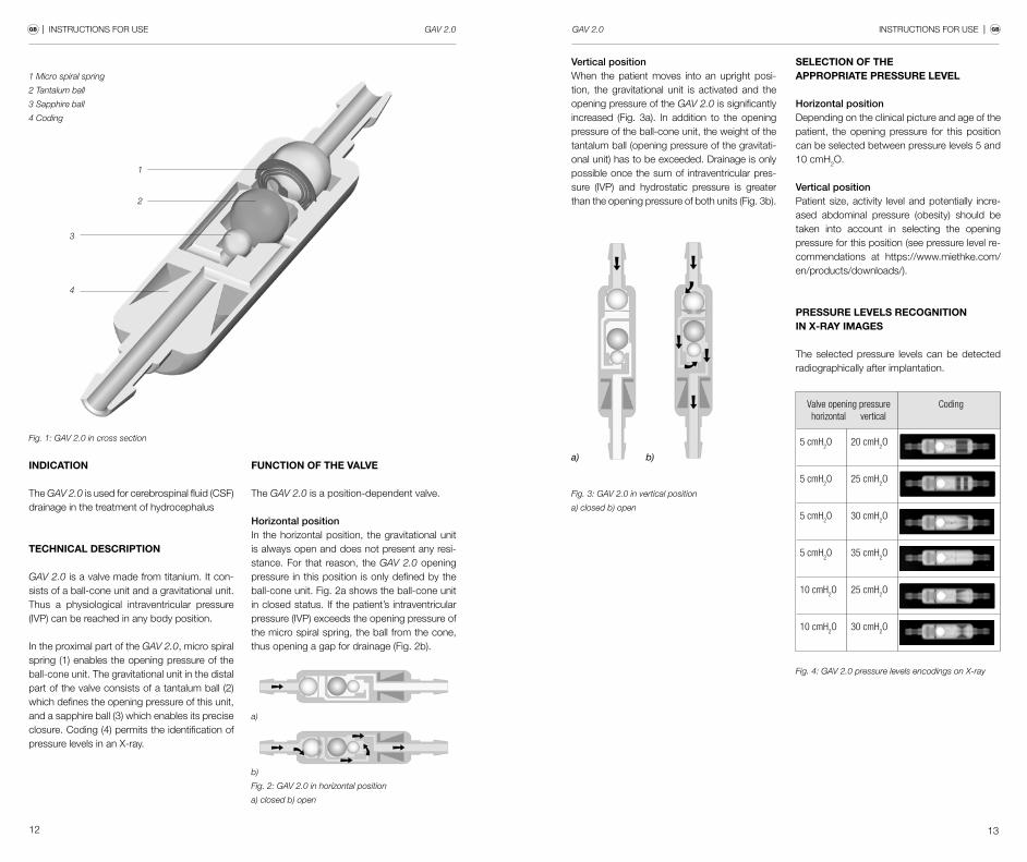


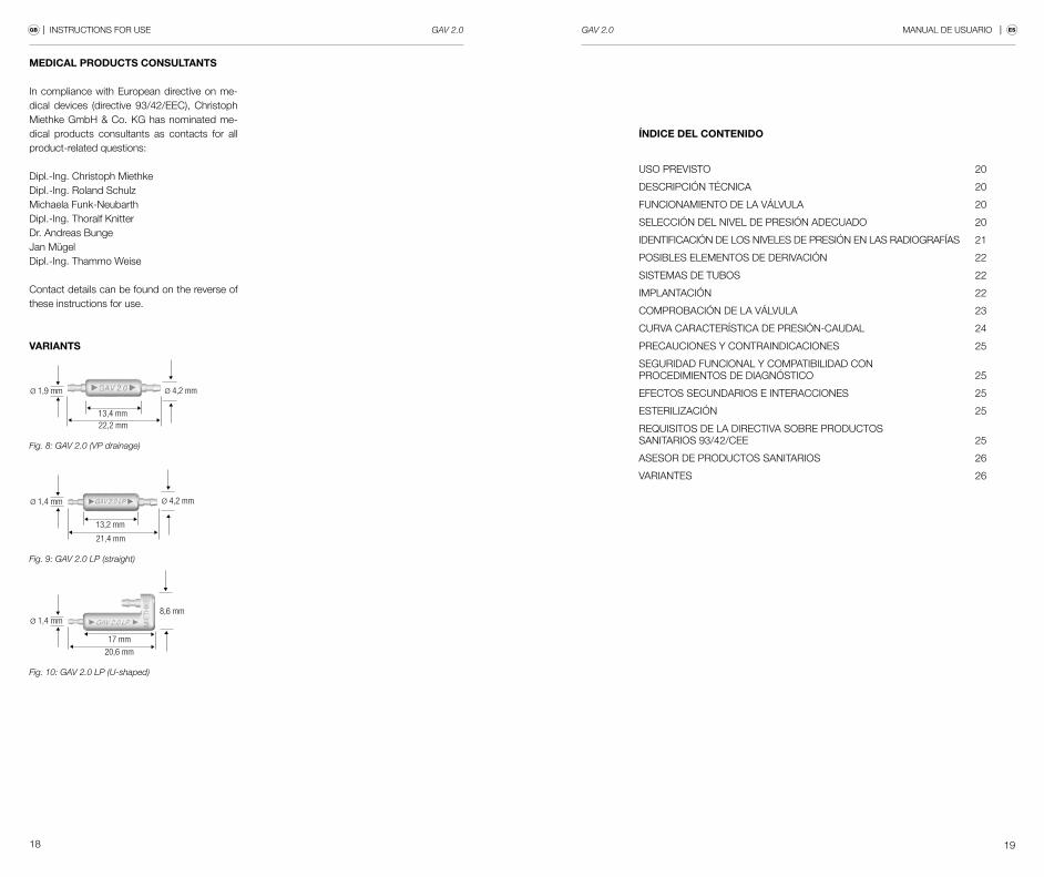


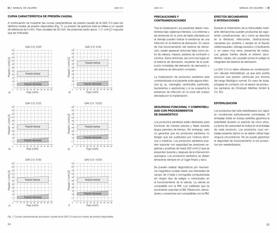

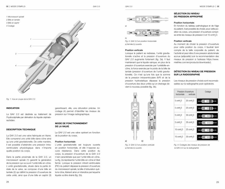


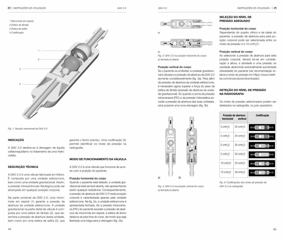


![Relative der and other Co elements in Danish · 2011. 3. 6. · (7a) *Manden [til som jeg gav bogen t] (7b) Manden [til hvem jeg gav bogen t] Man-the to ---/whom I gave book-the If](https://static.documents.pub/doc/80x56/6128e987fa446d0213321733/relative-der-and-other-co-elements-in-danish-2011-3-6-7a-manden-til-som.jpg)
