I41 Nations gdaw Defence nadonale AD-A262 921 __ CF-18 ANIALQ-126B-MG 13 lIP INTERFACE TO THE DREO ELECTRONIC WARFARE ENGAGEMENT SIMULATION FACILITY by James Loo and Serge Labeaume tO_._ DTIC I ~LrECTE APR26 1993 DEFENCE RESEARCH ESTABLISHMENT OTTAWA TECHNICAL NOTE 93-4 Canad -.. . November 1992 4: 22 031
Transcript
I41 Nations gdaw
Defence nadonale
AD-A262 921 __
CF-18 ANIALQ-126B-MG 13 lIP INTERFACETO THE DREO ELECTRONIC WARFARE
ENGAGEMENT SIMULATION FACILITY
by
James Loo and Serge Labeaume
tO_._
DTICI ~LrECTE
APR26 1993
DEFENCE RESEARCH ESTABLISHMENT OTTAWATECHNICAL NOTE 93-4
Canad -.. . November 1992
4: 22 031
Defence nabo~nele
CF-18 AN/ALQ-126B-MG 13 lIP INTERFACETO THE DREO ELECTRONIC WARFARE
ENGAGEMENT SIMULATION FACILITY
by
James Loo and Serge LabeaumeRadar Countermeasures Section - -
Electronic Warfare Division -
ByD
,., I AQaAi :'4. Or
t c la
DEFENCE RESEARCH ESTABLISHMENT OTTAWATECHNICAL NOTE 93-4
PCN November 1992021 Y6 Ottawa
ABSTRACT
This document describes the integration of the AN/ALQ-126B jammer and theMG-13 liP air intercept radar into the DREO Electronic Warfare EngagementSimulation Facility. The test configuration enables the jammer performance to beevaluated in an open-loop hardware-in-the-loop mode. The jamming waveforms fromthe AN/ALQ-126B can be observed and their effect on the MG-13's performance can bemonitored. Some recommendations for improving the simulator design are also made.
RtSUMI:
Ce document d6crit l'intdgration du syst~me de brouillage dlectroniqueAN/ALQ-126B et du radar d'interception MG-13 liP au Simulateur de Combat deGuerre Electronique du CRDO. La configuration des essais de l'dquipement en boucleouverte permet d'dvaluer les performances du brouilleur. Les signaux dmis par lebrouilleur AN/ALQ-126B ainsi que leurs effets sur le MG-13 peuvent etre observds surdcran. De plus, quelques recommendations visant l'am1lioration du simulateur sontfournies.
-Ill-
EXECUTIVE SUMMARY
The AN/ALQ-126B is the radar jammer carried aboard the CF-18 fighter aircraftto jam non-coherent pulsed radars. The jammer is software programmable and capableof generatir.n a variety of radar countermeasures signals. To evaluate the effectivenessof radar jammers and jamming techniques, the Defence Research Establishment Ottawa(DREO) has developed the Electronic Warfare Engagement Simulation Facility(EWESF).
This report describes fundamental concepts of electronic countermeasures (ECM)effectiveness evaluation, the EWESF layout, the AN/ALQ-126B radar jammer, and thejammer interface to the EWESF to jam the MG-13 liP air intercept radar. Some of theadvantages and disadvantages of the configuration are discussed. This is an interim taskreport documenting work performed under Director Avionics Simulators andPhotography (DASP) tasking 159 to investigate the basic operation and performance ofthe AN/ALQ-126B jammer and to study the effectiveness of jamming techniques againstdifferent radar systems.
This facility serves as a test bed for operating the jammer and testing its responseson different types of experimental radars. The test configuration is also useful for theCF-18 Integrated Support Station (ISS) project where open-loop jamming tests using newECM techniques may be performed as they are developed. These concepts may also beapplicable for evaluation of the RAMSES naval jammer which is used aboard theCanadian Patrol Frigate.
This report also discusses some limitations of the present test configuration anddiscusses several modifications to improve the performance and user-friendliness of theEWESF. These options include upgrading the scenario control computers and software,upgrading the tracking radar from the MG-13 configuration, and adding a continuoustarget angle motion capability.
4.0 MG-13 liP AIR INTERCEPT RAI)DR ................................ t4.1 System D escription ....... .......... ..................... h
5.0 SYSTEM INTEGRATION ............................5.1 System Interface Configuration .................... .......... . ,95.2 Computer Control of Scenario .................................. i
8.0 R EFER EN C ES .. ..................... ......................... 16
-vii-
LIST OF FIG LRES
Pagr
Fig. I Layout of a fully closed-loop hardware-in-the-loop simulator ......... 4
Fig. 2 Layout of EW ESF open-loop simulator ...........................
Fig. 3 Layout and Design of AN/ALQ-126B Jammer ....................
Fig. 4 Illustration of AN/ALQ-126B jammer interface to EWES"......
Fig. 5 Photograph of MG-13 airborne liP in E\VESF .................... I1
Fig. 6 Photograph of Radar and Opcrato r lnstru T1 tl(m .......... .... 1m
-ix-
LISTOF Al IBREIATIONS
AC alternating currentAFEWES Air Force Electronic Warfare Environment Sila hitorAM amplitude modulationCADJ counter anti-deception jammingCF Canadian ForcesCOSRO conical scan on receive onlyCW continuous waveDASP Director Avionics Simulators and PhotographyDREO Defence Research Establishment Otta-aECM electronic countermeasuresEW electronic warfareEWESF Electronic Warfare Engagement Simulation FacilityGTRS Generic Threat Radar SimulatorHOJ home on jamISS integrated support stationLORO lobe on receive onlyLOS line of sightPRF pulse repetition frequenctPRI pulse repetition intervalPWM pulse width modulatorRF radio frequency"1TL transistor-transistor-logicUDF user data file
-XI-
1.0 INTRODUCTION
1.1 Background
The AN/ALQ-126B jammer is used by the CF-18 fighter jet to provide self-protection jamming against non-coherent pulsed radar guided weapons systems. Thejammer is carried on board the CF-18 and provides an automatic response to jam enemyradars when the jammer detects a threat radar signal. The jamming responses to eachthreat radar are software programmable. The AN/ALQ-126B jammer is capable ofgenerating a wide variety of countermeasures techniques and an experimental facility isrequired to test and assess the fundamental effectiveness of these jamming techniques.The Directorate of Avionics Simulators and Photography (DASP) tasked the DefenceResearch Establishment Ottawa (DREO) under tasking DASP 157 to study theAN/ALQ-126B and to investigate the fundamental effectiveness of the jammingtechniques.
Electronic countermeasures (ECM) technique effectiveness testing can beperformed using a variety of methods. For optimum realistic simulation, flight trials ofthe CF-18 against actual or simulator mock-ups of enemy radars are required. In a fullflight trial, the CF-18 carries the AN/ALQ-126B jammer and radiates jamming signalsagainst actual radars. The effect of jamming on the radar can be closely monitored andECM effectiveness may be quantified by calculating missile flyout trajectories andassessing miss distances. Ideally, the flight is repeated using improved ECM techniqueseach time until an optimum technique is found. Another method of ECM evaluationconsists of testing a jammer in a hardware-in-the-loop configuration in which the jammeris integrated into a radar guided weapons simulator. A computer calculates simulationparameters and generates radar signals which are representative of those actuallyexperienced by the jammer in an engagement. The jammer receives these radar signalsand emits a jamming signal as a response. The jamming signal is processed by the radarsimulator and the degradation in the weapon system performance is assessed bymonitoring any missile or artillery trajectories. Digital modelling is another simulationtechnique in which the performance of the jammer, radar, and weapon system areentirely represented in software and the engagement is mathematically modelled [Ref. 11.
Each of these ECM evaluation techniques has its advantages and disadvantages.Flight trials provide the highest level of realism but are expensive to perform. In orderto scientifically evaluate jamming effectiveness, the victim radar must be fullyinstrumented and the effect of the ECM on the radar signal processing must be studied.Hardware-in-the-loop simulations test the jammer by stimulating it with representativethreat signals and then using.the actual jammer responses to degrade the threat radar.These simulations can be useful provided that the simulator has been validated and iswell designed to perform real-time simulations. Digital simulations provide the greatestflexibility for modelling different types of countermeasures and radars, however, digitalsimulations lack the realism of using actual jamming equipment. Digital simulations are
°-1
useful for research purposes, such as modelling complex engagement scenarios. EWscenarios can be modelled from high level down to the engineering emulation level.Software development costs can be high and the models require validation. All thesetypes of simulations play roles in the ECM effectiveness testing process.
The Radar Countermeasures Section of the Electronic Warfare Division ofDREO has been developing an anechoic chamber based hardware-in-the-loop simulatorfor evaluating ECM effectiveness. The objective of the Electronic Warfare EngagementSimulation Facility (EWESF) is to test jammers in a real-time, real-frequency, and real-power hardware-in-the-loop configuration in an anechoic chamber. The EWESF wasoriginally designed with the goal of achieving a closed-loop simulation capability. In aclosed-loop simulation, target and jamming signals ate processed by a victim radar andinfluence the overall performance of the weapons system. In electronic warfare (EW)research, closed-loop simulation requires the calculation of miss distances for a simulatedweapon system. A study [Ref. 2] was performed on the EWESF configuration and it wasconcluded that the EWESF laboratory could not meet the original objective of testingjammers in a closed-loop configuration. The processing requirements and simulationfidelity for real-time closed-loop missile trajectory calculation, and miss distances couldnot be met with the existing equipment. The EWESF uses an anechoic chamber tosimulate and radiate radar signals and it was concluded that the existing EWESF designcould not simulate target motion in angle. The EWESF can, however, serve as asimulation testbed for testing range deception jamming techniques and to investigate thebasic interactions between a jamming signal and the victim radar's signal processing.
1.2 Objective and Document Organization
This technical note describes the simulation facility, the AN/ALQ-126B jammer,the radar testbed, and interface of the jammer to the simulation facility. It alsodescribes the capabilities of the EWESF and the types of ECM tests that can beperformed. Limitations in the existing EWESF design are identified and someimprovements are presented.
The first section of this report discusses the simulator, the second sectiondiscusses the AN/ALQ-126B jammer, the third section discusses the MG-13 air interceptradar, and the fourth section discusses the interface in the testbed design. A discussionon different EWESF simulation aspects is presented and some proposals for simulatorimprovements are also made.
The EWESF simulates the electromagnetic environment of a radar-guided
weapons engagement. The simulation facility is designed to test on-board jammingequipment in a hardware-in-the-loop configuration incorporating free-space signalradiation through an anechoic chamber. In this type of configuration, a radar jammer isstimulated by threat radar signals and the jammer responds with actual jammingwaveforms. The target echo is combined with the jamming waveform and transmitted
through the anechoic chamber. The signals received by the threat radar should be
representative of those in an actual engagement. One of the main objectives of
employing an actual radar is to observe and monitor its electrical and dynamic response.The radar can be fully instrumented to monitor actual jamming and target signals. Fig. Iillustrates a design of a fully closed-loop hardware-in-the-loop simulator.
The EWESF tests equipment in an open-loop mode as depicted in Fig. 2. An
engagement scenario is generated at RF level and presented to a threat radar. The
reactions of the latter are recorded, but they are not fed back to influence the execution
of the scenario. The target motion is predefined and is not affected by the
countermeasures under test.
2.2 Basic Configuration
The EWESF uses an anechoic chamber to implement free space transmission of
radar skin return and jamming signals. A transmit antenna, consisting of a single
standard gain pyramidal horn located in the middle of one end of the anechoic chamber,radiates the simuiated radar skin return and the jammer generated countermeasures
signal. The radar antenna unit, which operates in receive mode only, is located at the
opposite end of the chamber. The radar signal processing circuitry is located outside the
anechoic chamber.
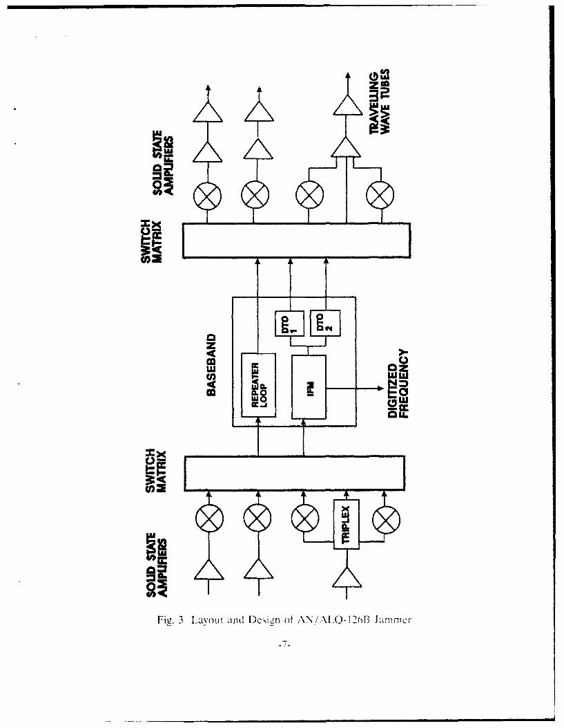
3.0 AN/ALQ-126B JAMMER
3.1 System Introduction
The AN/ALQ-126B is a non-coherent pulsed radar jammer carried aboard the
CF-18 fighter aircraft to provide self protection against radar guided weapons. The unit
is manufactured by Lockheed Sanders and is also carried aboard United States Navy
A-6, A-7 and F-14 combat aircraft. The jammer is primarily designed to jam target-
tracking radars and the jamming response for each threat is highly software
programmable. The jammer employs two main types of countermeasures techniques:
range techniques, which are used to deceive the range tracking loops of threat radars,
-3-
LU _
MI
v v•
L2U
Fig. 1 [Lavou t ot a t tUllv closed-Ilo01 hardw~i re - in th-Ill C. 1tit[
-4-
<, cc ccI I I
00o a
00a~Ow
Fig.~~~~~~~~~~ 2 u fLWS )rl-() iiuuo
and angle techniques, which are used against the angle tracking loops.
The AN/ALO-126B is highly software programmable and can generate a varietyof jamming techniques. It can operate in a pulse transponder or a pulse repeater modeagainst each threat radar. The jamming technique which is used depends on the threat'spriomity, available jamming power, and the trackability of the radar signal. To test thejammer in an open-loop hardware-in-the-loop configuration, a radar signal is fed into theinput receiver and the jamming output signal is injected into the victim radar.
Fie. 3 illustrates the microwave layout and system design of the jammer.
3.2 Jammer Testing Configuration
Fig. 4 is an illustration of the AN/ALQ-126B jammer interface to the EWESF.The jammer receives a radar signal from the MG-13 signal generation circuitry andradiates a jamming signal which is combined with the skin return and transmitted in theanechoic chamber. The creation and generation of jamming techniques for theAN/ALQ-126B is performed using an Intel minicomputer system. A hot bench supplies115 Volts AC and 400 Hz power to the AN/ALQ-126B. The jammer's response to theinput can be monitored on the system display test fixture which displays the threats beingjammed, their relative priorities, and the mode of the jamming technique. The jammer'srange jamming techniques are monitored using a crystal detector to detect the videoenvelope of the range jamming technique. The resulting signals are displayed on anoscilloscope and the frequency content of the jamming signal is displayed on a spectrumanalyzer.
4.0 MG-13 lip AIR INTERCEPT RADAR
4.1 System Description
The EWESF can use two radars for experiments: the Generic Threat RadarSystem [Ref. 3] and the MG-13 lip radar. The MG-13 lIP radar will be described in thisnote. The MG-13 lIP radar was built by Hughes Aircraft Company and provided airintercept functions (target search, acquire, and track) for the CF101B VooDoo fighterjet. The radar is no longer in service in the Canadian Forces, having been phased out inthe early 1980's.
The radar can operate in a frequency agile mode in the 8500 - 9250 MHz RFrange. The pulse repetition frequency (PRF) is 416 Hz for 1.0 As pulse width and it is910 Hz for 0.5 gs pulse width signals. The radar operates in a pulse repetition interval(PRI) jittered mode with 70 gs jitter and uses lobe-on-receive-onli (LORO) processingfor angle tracking. It can operate at four separate I:ORO frequencies: 8'). 122. 145. and185 H Iz. The radar transmits 250 kW peak power [Ref. 4].
-h-
4Z
z
El[Iic
n-r
Fig. 3 Layout and Design of ,\N/AL,-.O-]2oB kimmer
-'7-
uLJ
0 c
0 z
LUIz
Fi.4<~ ~ rto fA/L~I~Bjme nelc oL\LI
AAAAAYAA -8-
The MG-13 operator has a B-scan display which provides the target's location inazimuth and range. The navigator-operator identifies targets and manually positions arange gate over the selected target.
The radar tracks targets and provides steering information for the pilot to fly acollision course to intercept the target. The MG-13 mission computer incorporatesinformation provided by the radar and aircraft mounted gyroscopes to calculate anintercept course. When the aircraft approaches within weapons range of the target,ballistic ammunition such as bullets and unguided missiles are fired against the target.The radar did not provide a target illumination function for radar guided weapons.
The MG-13 tracking can be deceived if a jammer causes a breaklock or if thejammer introduces sufficient confusion pulses to make discrimination of the targetdifficult. Some counter-countermeasures features have been incorporated into thesystem. The MG-13 possesses a home on jam (HOJ) mode which can be activitated bythe operator if noise jamming is detected and the target cannot be tracked in range.When HOJ mode is entered, target range tracking is disabled and the radar only angletracks. When the radar enters burnthrough range, the operator disables HOJ and re-establishes range track on the target. The MG-13 possesses a counter anti-deceptionjamming (CADJ) mode in which the range gate can be biased to track the leading ortrailing edge of a chaff cloud. This feature prevents the MG-13 from locking onto thecentroid of chaff clouds and losing the target.
5.0 SYSTEM INTEGRATION
5.1 System Interface Configuration
The MG-13 installed in the EWESF is a stripped down version of the CF101Bconfiguration. The radar does not transmit radar energy into the anechoic chamber butonly operates in receive mode. The radar transmitter power is dissipated in a dummyload. In order to generate the MG-13 radar signal, a sample of the MG-13 magnetronCW RF frequency, 30 MHz below the carrier, is sampled and mixed with a stable30 MHz reference CW signal, which regenerates the original radar carrier frequency.The CW signal then serves as the RF source for the radar signal generator.
A radar high voltage transmit trigger is generated by the MG-13 and fed to thesimulator for timing purposes. The trigger is first conditioned to a transistor-transistor-logic (TTL) level which serves as an input to a radar range simulation unit, theBAK PX-219-P. The BAK range simulator delays the train of radar transmit triggers tosimulate propagation delay in space. The delay can be controlled dynamically tosimulate target motion in range. The target's acceleration is computer controlled. Sincethe AN/ALQ-126B jammer is carried on board the target, the range delay corresponding
"-9-
to propagation from the threat radar to the target jammer is the same as that from thejammer to the radar. The same range delay applies to both.
The range delayed trigger pulse modulates one of the CW channels to produce apulsed RF radar signal. A computer calculates the skin return power level in real-timeand attenuates the pulsed RF according to path loss and scintillation effects. Theresulting RF signal is fed to a power combiner.
Another sample of the CW signal is fed into a different RF modulator, then tothe AN/ALQ-126B input, as tie threat radar signal. The same range delayed trigger willpulse modulate the CW, but the RF level is attenuated based on a one way propagationloss calculation. The AN/ALQ-126B then receives the real power, real frequency, andreal-time radar signal. The jammer output is attenuated by a third RF modulator toaccount for the other one way propagation loss.
The jammer signal is extracted from the monitor output on the AN/ALQ-126Bhot bench facility. The signal is fed into the equipment rack patch panel where it isattenuated, combined with the skin return signal and then radiated into the anechoicchamber. The magnitude of the jamming signal is dynamically set by computercontrolled variable attenuators.
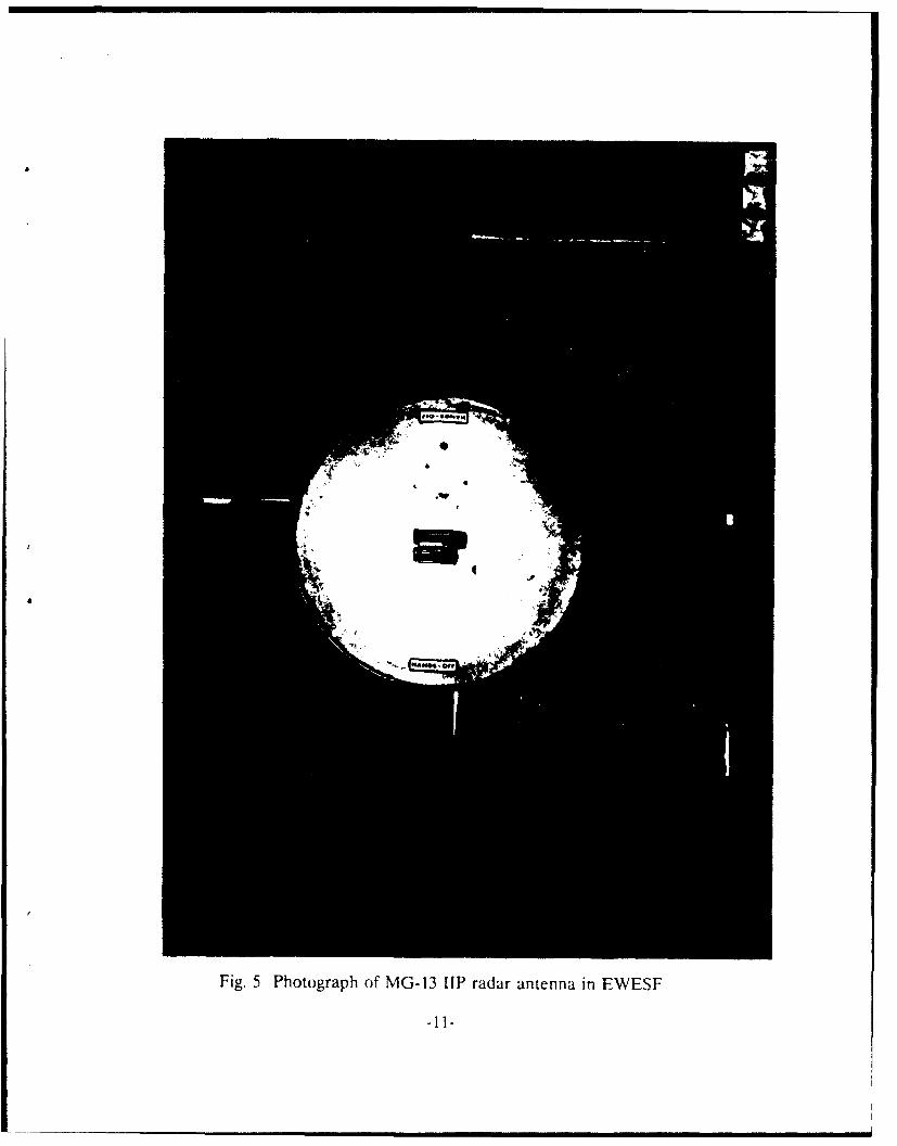
The MG-13 threat radar receiver receives a combined skin return and jammingsignal from the single target antenna. Fig. 5 is a photograph of the MG-13 radarantenna in the EWESF. It ts required to attenuate the power level of the skin returnpulses to account for the effectiveness of J/S levels as an experimental parameter. Fig. 4contains further details of the signal flow in the EWESF.
5.2 Computer Control of Scenario
A PDP 11/84 minicomputer controls the signal levels of the simulation. TheMG-13 radar signals are simulated by generating an actual pulse delay due topropagation time and are attenuated to simulate path losses due to range propagation.The computer provides the RF modulators and Radar Range Simulators with thenecessary control information to synthesize a target which moves along a pre-definedflight profile. The computer program is written in Pascal and uses PDP 11 macrolanguage to implement lower level functions.
Target range simulation is performed by a range modulator (BAK PX-219-P)which is manually or computer controlled. The following formula for range R isimplemented in hardware:
R -R, +K t V., Kt!,,11
-10-
-OPP
Fig. 5 Photograph of MG-13 UiP radar antenna in EWESF
-11-
The BAK unit requires the target's initial range (R0), initial velocity (V0), andinitial acceleration (A0). The values K, and Ka, are velocity and acceleration constantsand t denotes simulation time. When the initial parameters are input to the BAK, itbecomes a stand-alone unit that uses the MG-13 radar transmit trigger as a clock for itsinternal counters. The BAK unit introduces a time delay to account for round-trip signalpropagation. The parameters cannot be dynamically changed apart from theacceleration.
The amplitude modulation due to range is performed under computer control.The Antekna modulators serve as computer controlled variable attenuators. Theattenuation level is computed by the scenario controller which implements the radarequation to generate the required power levels at the threat radar.
The width of the RF pulse is controlled by either the BAK range units or by aPulse Width Modulator (PWM) inserted between the BAK and RF modulators. TheBAK unit has two possible pulse widths: 0.2 As and 2.5 As, and the PWM can generatepulse widths in the 0.1 - 6.0 As range. The PWM is also under computer control. Sincethe target is confined to move in a radial direction relative to the radar, the computercontrol contribution is limited. The computer exercises dynamic control over theattenuation levels of the skin return and the jamming return. There is no tangentialmotion of the target relative to the threat radar so target angular motion need not besimulated.
5.3 Operating Procedure
The radar is initially put into a search mode and the MG-13 sweeps from left toright to detect a target. When a target is detected, the operator then manually positionsa range gate over the target return. The azimuth motion is controlled by a lateralmotion of a joystick, while elevation motion is controlled by adjusting a thumbwheel.The range gate is engaged by depressing the joystick trigger, and controlled by a verticalmotion of the joystick. Once the joystick trigger is released, the MG-13 proceeds toacquire and track the designated target. The operator may observe target returns andjamming on the A-scope display. If the range gate loses track of the target or tracks afalse jamming pulse and is then dumped, the operator must manually re-acquire thetarget. Fig. 6 shows the radar and the radar operator's instrumentation.
-12-
IL
Figi
Fi.6 Photograph of Raidar and Operator Instdrumentatio
-13-
6.0 CONCLUSION AND DISCUSSION
This report described the DREO EWESF and its interface with theAN/ALQ-126B jammer and the MG-13 IlIP air intercept radar. The simulator is anopen-loop hardware-in-the-loop design and it serves as a testbed for performingexperiments on the fundamental effectiveness of electronic countermeasures techniquesagainst selected victim test radars.
Different types of open-loop experiments can be conducted in the EWESF.These include: examining the basic properties of range jamming parameters, examiningjamming power requirements to deceive a radar, and studying the limits of jammingparameters which are effective. Angle tracking jamming techniques may also be testedwith this facility, but a different type of test'radar would be required. For example,inverse gain jamming can be tested but only against conical scan or conical scan onreceive only (COSRO) radars. In these applications, a variation in the line of sight isnot necessary to introduce angle tracking errors. Jamming techniques which require avariation in the line of sight to be effective can not be evaluated in this facility due tothe lack of target angular motion simulation capability.
The simulator can also serve as a useful training and analysis tool for the jammertechnique development process. When an ECM analyst or jammer operator designs anew jamming technique, the technique can be quickly tested in the EWESF to assess itsgeneric effectiveness. The radar in the EWESF may not be representative of the thedesired victim radar and the jamming degradation may not be quantifiable but thesimulator provides a means to examine the ECM signal. The EWESF can be a usefultool for generating and observing ECM techniques in preparation of actual CF-18 ECMflight trials. Flight trials provide the actual research environment for assessing techniqueeffectivness and observations made during these trials can be first observed in alaboratory environment. Flight ranges at Eglin Air Force Base can be used to calculatemissile flyouts and assess ECM effectiveness. The threat radars against which theaircraft flies must be well instrumented to perform a thorough scientific assessment oftechnique effectiveness. The facility can be used to supplement the functions of the CF-18 AIR ISS and its objective of generating and performing basic testing on the CF-18jammer's user data files as they are developed.
If laboratory-generated missile miss distances are required, a closed-loop missileflyout model is required to quantitively assess radar countermeasures effectiveness. Thisis best performed at a simulation facility such as the Air Force Electronic WarfareEnvironment Simulator (AFEWES) or Radio Frequency Simulation System (RFSS).These facilities have validated and instrumented hardware-in-the-loop simulators wherejamming techniques can be repeated and their effects closely monitored. Repetitivesimulation runs using different parameters can be performed to optimize ECMtechniques.
.14.
7.0 EWVESF ENHANCELME'NTS
The present simulator configuration is limited to performing the open-loop ECMtests described in this report. The simulator's performance and ease of use is limitedand several modifications can be performed to enhance its capability. However, it isunlikely that the EWESF will be upgraded to achieve a real-time closed-loop simulationcapability which can be used to quantify ECM techniques and generate weapon missdistances. This option is expensive and it is more cost effective to use foreign simulationfacilities such as AFEWES or RFSS.
Possible upgrades for the EWESF are discussed below:
Replacement Computers: The current PDP 11/84 target control computer has limitedprocessing speed and will be unable to meet higher simulator control input/outputrequirements. The computers are being replaced by microcomputers. The computer canalso digitize radar and jammer parameters in time for subsequent processing during dataanalysis. A higher performance processor would enable the usage of a real-time missilemodel to compute missile flyout trajectories. Closing the loop would still require real-time processing capability for synchronization with hardware input/output.
Replacement Software: The present simulation software structure does not provideflexibility for expansion. The control software is written in PDP 11 Pascal with lowerlevel routines written in PDP 11 macro. The software is being re-written in a moreinput/output oriented language such as the C computer language.
Replacement Radar: the radars usable in the EWESF are presently limited to those inDREO inventory. The Generic Threat Radar Simulator (GTRS), can also be used inthe EWESF. The GTRS possesses a monopulse antenna and its receiver uses a type ofscan with compensation processing. To further investigate the basic jamming capabilitiesof the AN/ALQ-126B, different types of radar angle tracking designs such as: conicalscan, track-while-scan, two and three channel monopulse systems should be tested againstthe AN/ALQ-126B . However, the successful jamming of these radars requirescombination of ECM and aircraft maneuvers.
Target Angular Motion: if a longer term objective of improving the ECM simulationcapability at DREO is required, the EWESF could be designed to perform limitedclosed-loop simulations in which realistic target angular motion can be simu ated. Sincethe target and jammer are radiated from a single source and the radar antenna is fixed,the present EWESF configuration is only suitable for evaluating range jammingtechniques and cannot stress the threat radar angle tracking loops. The E\VESF doesnot currently have target angular motion capability to represent radar line-of-sightvariations in the tangential direction. If angle tracking must be tested in a technique.target angular motion is reCluired. This can be achieved through use of a multiple axismotion pedestal to position and support the threat radat or through some type of
-15-
mechanism to move the target in angle. The target motion can also be simulatcd inangle by using an antenna array system [Ref. 51 to change the apparent location of atarget, or by using a mechanical positioner to move a single RF source. Scveral of theeissues are discussed in [Ref. 2]. The EWESF is being upgraded to possess a continuoustarget motion capability using a horizontal positioner with two target antennas.
8.0 REFERENCES
[11 Eichblatt, E.J., ed., -Test and Evaluation of the Tactical Missile,Volume 19. Progress in .Astronautics and Aeronautics, American Instituteof Aeronautics and Astronautics. Inc., 1989.
[2] Loo. J. and W.K. McRitchie., "Considerations For ECM Testing AtDREO", DREO Technical Note 90-15. September 1991.
[4] Hughes Aircraft Company, "MG-13 Type Fire Control System. FieldMaintenance -- Technical Manual", February 1977.
[5] Charland, S., "An Investigation of the Transfer of Monopulse TrackingBetween Two Coherent Point Sources", DREO Technical Note 89-15.August 1989.
-16-
UNCLASSIFIED
SECURITY CLASSIFICATION OF FORM 17(highest classification of Title, Abstract, Keywords)
DOCUMENT CONTROL DATA(Security clessification of title, body of abstract and indexing annotation must be entered when the overall document % cliassified)
1. ORIGINATOR (the name and address of the organization preparing the document. 2. SECURITY CLASSIFICATIONOrganizations for whom the document was prepared, e.g. Establishment sponsoring (overall security classification of the document.a contractor's report, or tasking agency, are entered in section 8.) including special warning terms if applicoble)
DEFENCE RESEARCH ESTABLISHMENT OTTAWANATIONAL DEFENCESHIRLEY BAY, OTTAWA, ONTARIO KIA OK2 CANADA UNCLASSIFIED
3. TITLE (the complete document title as indicated on the title page. Its classification should be indicated by the appropriateabbreviation (S.C or U) in parentheses after the title.)
CF-18 AN/ALQ-126B -- MG-13 lIP INTERFACE TO THE DREO ELECTRONIC WARFARE ENGAGEMENT
SIMULATION FACILITY (U)
4. AUTHORS (Last name, first name, middle initial)
LOO, JAMES AND LABEAUME, SERGE
5. DATE OF PUBLICATION (month and year of publication of 6a NO. OF PAGES (total 6b. NO. OF REFS (total cited indocument) containing information. Include document)
Annexes, Appendices, etc.)
21 57. DESCRIPTIVE NOTES (the category of the document, e.g. technical report, technical note or memorandum. If appropriate, enter the type of
report, e.g. interim, progress, summary, annual or final. Give the inclusive dates when a specific reporting period is covered.)
DREO TECHNICAL NOTE
B. SPONSORING ACTIVITY (the name of the department project office or laboratory sponsoring the research and development. Include the
DIREtk OF AVIONICS SIMULATORS AND PHOTOGRAPHY (DASP)
NATIONAL DEFENCE HEADQUARTERSMGEN GEORGES R. PEARKES BUILDING, OTTAWA, ONTARIO KIA 0K2 CANADA
9a. PROJECT OR GRANT NO. (if appropriate, the applicable research 9b. CONTRACT NO. (if appropriate, the applicable number underand development project or grant number under which the document which the document was written)was written. Please specify whether project or grant)
021Y6
10a. ORIGINATOR'S DOCUMENT NUMBER (the official document 10b. OTHER DOCUMENT NOS. (Any other numbers which maynumber by which the document is identified by the originating be assigned this document either by the originator or by theactivity. This number must be unique to this document) sponsor)
DREO TECHNICAL NOTE 93-04
1 1. DOCUMENT AVAILABILITY (any limitations on further dissemination of the document, other than those imposed by Security classification)
(X) Unlimited distribution
I Distribution limited to defence departments and defence contractors; further distribution only as approved
Distribution limited to defence departments and Canadian defence contractors; further distribution only as approved
Distribution limited to government departments and agencies; further distribution only as approved
Distribution limited to defence departments; further distribution only as approved
Other (please specify):
12, DOCUMENT ANNOUNCEMENT (any limitation to the bibliographic announcement of this document This will normally correspond tothe Document Avallabilty (11). However, where further distribution (beyond the audience specified in 11) is possible, a widerannouncement audience may be selected.)
UNCLASSIFIED
SECURITY CLASSIFICATION OF FORM
OC103 2/06/87
18 UNC'.ASSIFIEDSECURITY CLASSIFICATION OF FORM
13. ABSTRACT ( a brief and factual summary of the document It may also appear elsewhere in the body of the document itself. It is highly
desirable that the abstract of classified documents be unclassified. Each paragraph of the abstract shall begin with an indication of thesecurity classification of the information in the paragraph (unless the document itself is unclassified) represented as (SI, (C), or (U).It is not necessary to include here abstracts in both offical languages unless the text is bilingual).
(U) This report describes the integration of the AN/ALQ-126B jammer and the MG-13UiP air intercept radar into the DREO Electronic Warfare Engagement Simulation Facility.
The test configuration enables the jammer to be evaluated in an open-loop hardware-
in-the-loop mode. The jamming wavefors from the AN/ALQ-126B can be observed and theireffect on the MG-13's performance can be monitored. Some recommendations for improvingthe simulator design are also made.
14. KEYWORDS. DESCRIPTORS or IDENTIFIERS (technically meaningful terms or short phrases that characterize a document and could behelpful in cataloguing the document They should be selected so that no security classification is required. Identifiers. such as equipmentmodel designation, trade name, military project code name, geographic location may also be included. If possible keywords should be selectedfrom a published thesaurus. e.g. Thesaurus of Engineering and Scientific Terms (TEST) and that thesaurus-identied. If it is not possible toselect indexing terms which are Unclassified, the classification of each should be indicated as with the title.)


![AD-A262 '111 J I 'i t! ill~J],! 754 I~li iii IIHOSPITALITY ... · collected from either top management company personnel and/or ... responding to the many follow-up phone calls. In](https://static.documents.pub/doc/80x56/5f3dc3e7b67bbd153e144d2c/ad-a262-111-j-i-i-t-illj-754-ili-iii-iihospitality-collected-from-either.jpg)


